

Page 1

Quick Installation Guide
(External Preview Version)
© 2016 PSP Security Co. Ltd. All rights reserved
Page 2
AccuFACE® EFR-T3 Series Quick Installation Guide
Version 1.0
A. Preparation
The following peripherals are required for installing AccuFACE:
• Mounting bracket
• 12 VDC power supply with at least 1.5 Amps output
• Standard Ethernet cable
• Screws 4~6x
• Special screws 2x
B. Wiring
1. Back Panel
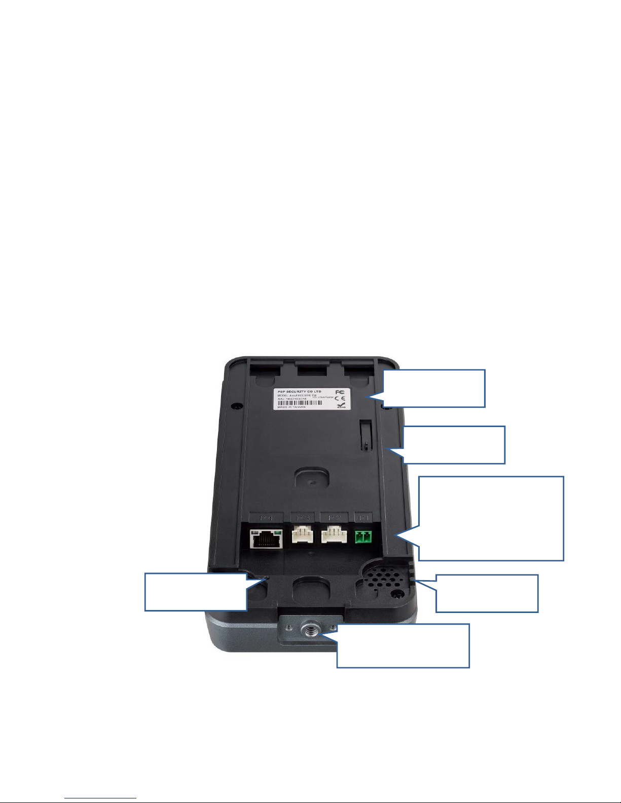
Below describes the functionalities of back panel at the back of the AccuFACE.
Ports:
P1: Power Supply
P2: Digital I/O
P3: Communication
P4: Network
Tamper
Alarm
Hidden Reset
Button
Serial Number
Label
Speaker &
Buzzer
Threaded Hole for
Tripod Mount
Page 3
2. Port Pins
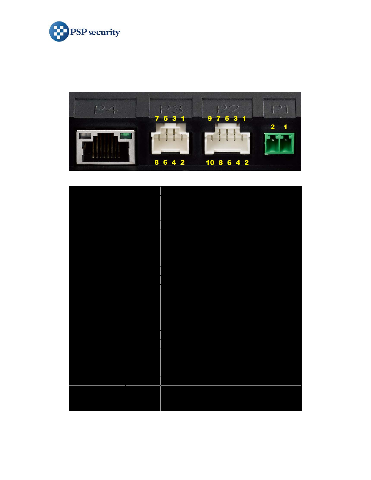
The AccuFACE has four ports located at the back of the unit, for power supply,
digital I/O, communication, and network interface.
Port
Pin#
Definition & Color
P1
(Power)
1
12V POWER SUPPLY
2
12V POWER GND
P2
(Digital I/O)
1
Brown
12V DC OUT
2
Black
12V DC OUT
3
Pink
DOOR SENSOR INPUT
4
Purple
EXIT SWITCH INPUT
5
White
RELAY 1 COM
6
Gray
RELAY 2 COM
7
Green
RELAY 1 NC
8
Yellow
RELAY 2 NC
9
Blue
RELAY 1 NO
10
Orange
RELAY 2 NO
P3
(Communication)
1
Red
12V Power OUT
2
Black
12V Power OUT GND
3
Blue
Wiegand IN Data 0
4
Gray
Wiegand IN Data 1
5
Green
Wiegand OUT Data 0
6
White
Wiegand OUT Data 1
7
Orange
RS232 Tx
8
Yellow
RS232 Rx
P4
(Network)
Standard Gigabit Ethernet
Page 4

AccuFACE® EFR-T3 Series Quick Installation Guide
Version 1.0
3. Typical Wiring Schematics
Page 5
C. Installation
1. Installing
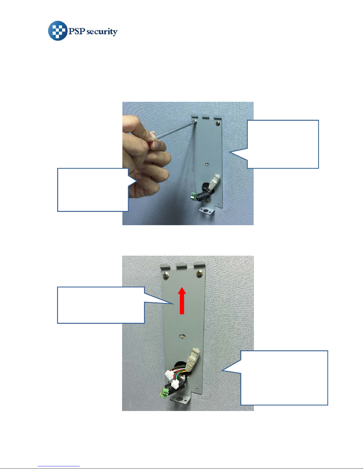
Follow below steps to install AccuFACE:
Decide the
appropriate height
to mount AccuFACE
(see the table below)
Ensure power, network,
communication, and I/O
cables are available from
the opening of the
mounting bracket
Ensure AccuFACE is
vertically installed and
parallel to a vertical wall
Apply screws to
tighten the
mounting bracket
on the wall
Page 6
AccuFACE® EFR-T3 Series Quick Installation Guide
Version 1.0
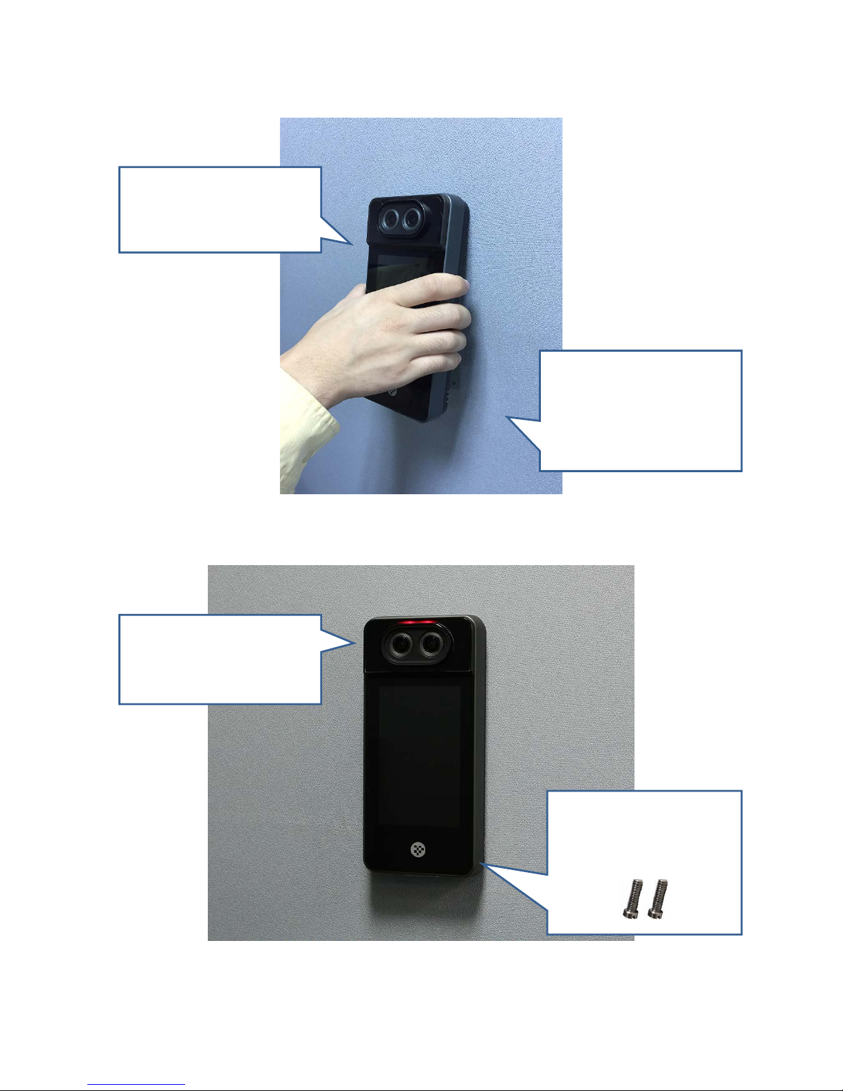
Finally, mount two
special screws at the
bottom of AccuFACE
Power up AccuFACE to
test if all the cables are
connected correctly
Connect all the cables to
the ports, and mount
AccuFACE gently
Hook the top of the
bracket and press it down.
Slide the unit down to
reach the bottom of the
bracket
Page 7
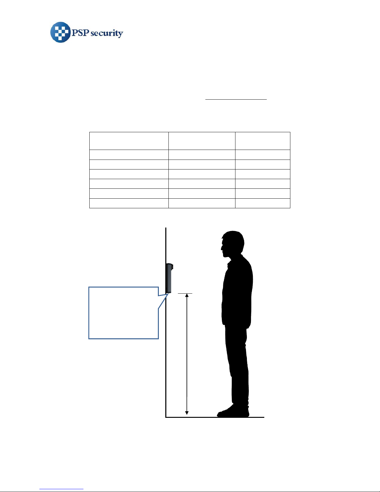
2. Installation Height Consideration
More about installation height:
• For inst allat ion with multiple AccuFACE, all units (including un it used for
user enrollment) must be installed at the same height
• Installation height depends on end user’s minimum and average height
• See below table to find the appropriate installation height
Installation height of
AccuFACE
(H)
Minimum user
height
Maximum
user height
1.05 m
1.30 m
1.70 m
1.10 m
1.35 m
1.75 m
1.15 m
1.40 m
1.80 m
1.20 m
1.45 m
1.85 m
1.25 m
1.50 m
1.90 m
1.30 m
1.55 m
1.95 m
Installation height
(H) measured from
the bottom of
AccuFACE to
ground
Page 8

AccuFACE® EFR-T3 Series Quick Installation Guide
Version 1.0
D. More
 Loading...