

Page 1

PQube 3 Installation Manual
Page 1 of 48
PQube® 3 Power Analyzer
Installation Manual
Revision 3.1
© 2008-2019 Power Standards Lab
Power Standards Lab
980 Atlantic Ave
Alameda CA 94501 USA
Page 2
PQube 3 Installation Manual
Page 2 of 48
If this equipment is used in a manner not specified by the manufacturer, the protection provided by
the equipment may be impaired. Installation, service, and maintenance of your PQube 3 must only
be done by qualified personnel for electrical installations.
The information contained in this document is subject to change without notice.
PSL MAKES NO WARRANTY OF ANY KIND WITH REGARD TO THIS MATERIAL, INCLUDING, BUT NOT
LIMITED TO, THE IMPLIED WARRANTIES OF MERCHANTABILITY AND FITNESS FOR A PARTICULAR
USE.
PSL shall not be liable for errors contained herein or for incidental or consequential damages in
connection with the furnishing, performance, or use of this material. If you do not accept this
limitation on liability, please return the product to PSL prior to use.
Produced in the United States of America.
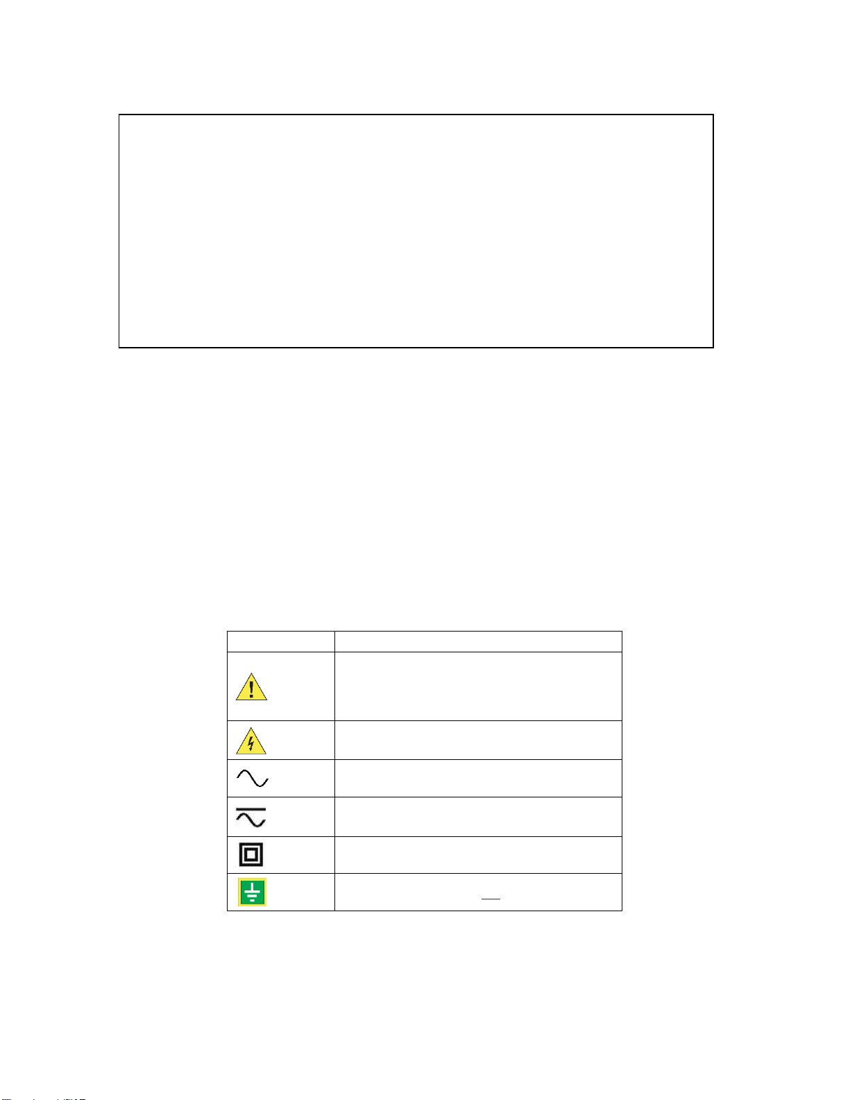
Symbol
Meaning
Caution. Consult this manual in all cases where this
symbol is marked, in order to find out the nature of
the potential hazards and any actions which have
to be taken to avoid them.
Caution. Risk of electric shock
Alternating current
Alternating current (a.c.) or direct current (d.c.)
Double or Reinforced insulation
Functional earth terminal not relied on for safety
© 2008-2019 Power Standards Lab. All rights reserved. No parts of this document may be copied, reproduced, or translated to another
language without the prior written consent of Power Sensors Ltd. “PQube 3” is a registered trademark of Power Standards Lab. “Windows”
“Excel”, and “PowerPoint” are registered trademarks of Microsoft Corporation. All product names, trademarks and registered trademarks
are property of their respective owners.
WARNING: Death, serious injury, or fire hazard could result from improper connection or
operation of this instrument. Carefully read and understand manual before connecting this
instrument.
AVERTISSEMENT: Si l'instrument est mal connecté, la mort, des blessures graves, ou un
danger d'incendie peuvent s'en suivre. Lisez attentivement le manuel avant de connecter
l'instrument.
WARNUNG: Der falsche Anschluß dieses Gerätes kann Tod, schwere Verletzungen oder Feuer
verursachen. Bevor Sie dieses Instrument anschließen, müssen Sie die Anleitung lesen und
verstanden haben.
ADVERTENCIA: Una conexión incorrecta de este instrumento puede producir la muerte,
lesiones graves y riesgo de incendio. Lea y entienda el manual antes de conectar.
Page 3

PQube 3 Installation Manual
Page 3 of 48
/1 Introduction 5
1.1 What is a PQube® 3? ......................................................................................................... 5
What software do you need? 6
Which power configurations are supported? 6
How do I power my PQube 3? 6
Easy operation and communication with PQube 3? 6
1.2 How is the PQube 3 Unique? ............................................................................................ 7
1.3 Overview of PQube3 models and modules ....................................................................... 8
1.3.1 PQube 3 8
1.3.2 PQube 3e 8
1.3.3 PQube 3v 9
1.3.4 PQube 3r 9
1.3.5 Modules and Accessories 10
1.4 Overview of PQube 3 Ports, Connections and Controls .................................................. 12
1.5 Choosing Modules .......................................................................................................... 13
1.5.1 Power your PQube 3 from 100~240Vac (PM1/PM2) 13
1.5.2 Backup your PQube 3 during a power outage (UPS1/UPS2/UPS3) 13
1.5.3 Measure currents from secondary of current transformers (CTI-1A/CTI-5A) 14
1.5.4 Three Phase AC/Dual DC Voltage Attenuator 14
1.5.5 Relay Extension Module for load shedding (RM8) 15
1.5.6 Measure Environmental Conditions (ENV2) 15
1.5.7 Synchronize your PQube 3 clock to GPS time 16
2 Installing Your PQube 3 17
2.1 Unpacking your PQube 3 ................................................................................................ 17
2.2 Installation ...................................................................................................................... 17
2.2.1 Disconnect mains prior to servicing 17
2.2.2 Mount your PQube 3 properly and securely 17
2.2.3 Include overcurrent protection and a disconnecting device 18
2.2.4 Protect the operator from the hazardous terminals 18
2.2.5 Connect your PQube 3 to the power supply 19
2.2.6 Connecting the wires 22
2.2.7 Connect mains AC voltage wires 24
2.2.8 Protect antenna terminals from lightning 25
Page 4

PQube 3 Installation Manual
Page 4 of 48
2.2.9 Installing Your PM1 Power Supply Module 25
2.2.10 Installing Your UPS Module 25
2.2.11 Installing Split Core Current Transformers (CTs) 26
26
2.2.12 Connecting the ENV2 environmental probes 30
2.2.13 Installing Your MS1 Sync Module (if GPS synchronization needed) 31
3 Wiring Diagrams 32
3.1 Wiring diagram for PQube 3v ......................................................................................... 32
3.2 Wiring Diagrams (PQube 3, PQube 3e, PQube 3r) .......................................................... 33
3.2.1 Single Phase L1-L2 33
3.2.2 Single Split Phase 34
3.2.3 Delta – 3 CTs 34
3.2.4 Delta – 2 CTs (PQube 3 calculates current on remaining channel) 35
3.2.5 Wye/Star 35
3.2.6 Measuring Neutral Current (applies to any power configuration with Neutral) 36
3.2.7 Measuring Earth Current (applies to any power configuration) 36
3.2.8 Measuring Net Earth Current – Delta 37
3.2.9 Measuring Net Earth Current – Wye/Star 37
4 Configuring Your PQube 3 38
4.1 Using the Configurator .................................................................................................... 38
4.2 Initial Device Setup ......................................................................................................... 40
4.2.1 Set Your Potential Transformer (PT) Ratio 40
4.2.2 Set Your Current Transformer (CT) Ratio 41
4.2.3 Troubleshooting: Common Installation Errors 44
5 Maintenance 46
5.1.1 Turning Off Your PQube 3 46
5.1.2 Replacing Your PQube 3’s Clock Battery 46
5.1.3 Life Expectancy of the PQube 3 and the PM1/PM2 module 46
5.1.4 UPS1 Life Expectancy and Long Term Storage Instructions 46
5.1.5 Cleaning Instructions 47
5.1.6 Reasons for reset 47
5.1.7 Calibration Information for Your PQube 3 47
6 PQube 3 Technical Specifications 48
Page 5

PQube 3 Installation Manual
Page 5 of 48
1 Introduction
1.1 What is a PQube® 3?
PQube® 3 is an instrument for both monitoring and diagnosing issues with electric power systems
and sensing environmental conditions, helping you to quickly solve problems that impact the quality
and reliability of your product or process.
Think of it as a black box for your electric power, environment and process: It is a unique combination
of the best features of a power disturbance monitor, a power/energy meter, a process and
environment data logger, and a digital fault recorder. It’s easy to install, easy use. No special training
is required, no software required.
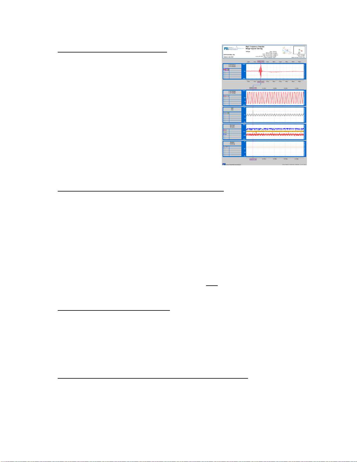
What does the PQube 3 record?
In a few words, your PQube 3 detects and records disturbances on the mains circuit: Sags/dips,
swells, interruptions, frequency variations, HF impulses, Rapid voltage changes, waveform changes
and more... It also records steady state power quality parameters like flicker, unbalance, THD
harmonics and interharmonics. PQube 3 is compliant with the most stringent Power Quality
measurement standards: Class A IEC 61000-4-30 Ed3 (2015).
The PQube 3 is one of the few analyzers that measure 2kHz-150kHz conducted emissions.
Your PQube 3 automatically generates daily, weekly, and monthly trends/statistics reports.
When connected to compatible current transformers, your PQube 3 records current waveforms,
RMS magnitude, current unbalance and powers (watts, watt-hours, VAR’s, power factor, and other
power-related parameters). The PQube 3 can monitor power and energy on several circuits.
The PQube 3 when equipped with PSL ultra-precise CTs, is fully compliant with IEC 61000-4-30,
edition 3 Class A certified requirements and can be used as a revenue grade Class 0.2 energy meter.
Your PQube 3 includes 4 general purpose channels for interfacing with many type of sensors (RPM,
torque , flow , vibration…). It has a digital input, which can be used as an eternal trigger source, and
a relay contact output, used to notify alarms to an external indicator or PLC (the relay opens for at
least 3 seconds for any detected event).
Your PQube 3, with up to 2 optional ENV2 environmental probes, can measure and trigger on
temperature, humidity, barometric pressure and mechanical shocks, seismic disturbances and
vibration.
Page 6
PQube 3 Installation Manual
Page 6 of 48
What software do you need?
You don’t need special software to use your PQube 3. It records
all data on internal memory plus a removable microSD card.
No special software is required – just open the GIF picture files
with standard image programs, Microsoft Word® and Microsoft
PowerPoint®, or open the CSV files with any spreadsheet program
such as Microsoft Excel®.
You configure your PQube 3 with our free PQube 3 Configurator
program.
Which power configurations are supported?
Your PQube 3 can monitor circuits anywhere in the world (from single-phase, split-phase to various
types of 3-phase configurations: wye, delta, open delta, corner grounded delta.
It can auto-detect nominal voltages from 57.5VAC up to 600 VAC phase-to-phase, 960VAC phase-tophase. It can auto-detect mains frequencies of 16.7 Hz, 50 Hz, 60 Hz, and 400 Hz. For medium and
high voltage applications, your PQube 3 supports PT ratios (up to 50000:1) and also CT ratios.
Beyond AC voltage, your PQube 3 can be used to monitor DC voltage at up to 60VDC, or up to 1200V
DC with an optional interface module (ATT1). For both DC voltage and DC current use the ATT2
interface module. For example, which can be useful for applications such as monitoring photovoltaic
generation sites or battery banks of UPS.
Your PQube 3 with an additional module (VAT1) can monitor both the input and output of a 3-phase
UPS.
How do I power my PQube 3?
It can be directly powered from 24V AC or 24~48V DC source.
If a network hub with Power over Ethernet is available, the PQube 3 can power from its Ethernet
port (PoE).
If a wall power socket is available, you can power the PQube 3 with a snap-in PM1/PM2 module
(range AC 100VAC ~ 240VAC, 50/60Hz, or 120VDC ~ 370VDC)
Easy operation and communication with PQube 3?
No network is required to retrieve files from your PQube 3. Simply copy the data using a USB thumb
drive or microSD card.
If a network connection is available, PQube 3 can automatically send you e-mails whenever it detects
an event. You can use emails the PQube 3 to send a new setup file, and update its firmware. It
Page 7

PQube 3 Installation Manual
Page 7 of 48
includes a built-in web server, FTP server, and supports communication protocols including MODBUS
TCP/IP, SNMP and DNP3.
1.2 How is the PQube 3 Unique?
There are many power quality meters, energy meters, and energy recorders available. What makes
the PQube 3 unique?
No software. Open data. – No specific software is required. All the data that the PQube 3 records
are in standard easy to understand open formats. No need to buy or lease software from PSL, or pay
a fee to see or use your data.
Friendly data. –Data is organized and presented to you in a format you can understand.
Works out of the box, or you can customize your configuration – Auto configuration, enables you
to instantly measure and start recording data. You can change almost any setting using the PQube
3 Configurator program.
Works with or without a network – Plug the cable into your PQube 3’s Ethernet port and get emails
when an event occurs, use your Internet browser to navigate through recorded events and trends.
Real time measurements are also available via communication protocols such as Modbus/TCP,
SNMP (including traps), or DNP3.
Don’t have a network? You can extract the data onto a USB thumb drive (or micro SD) and look at
all the files on any computer without proprietary software.
Store years of data in its internal flash memory. – Your PQube 3 comes with an external microSD
card which holds a backup for the internal memory. It automatically deletes the oldest data when it
becomes full, so no maintenance is required. You can take this card with you while your PQube3
continues to measure and store recordings.
Ultra-compact size – The PQube 3 is tiny, making it easy to integrate into your equipment, enclosure,
or electrical panel.
Great value – The PQube 3 provides high-end features at an affordable price.
Page 8
PQube 3 Installation Manual
Page 8 of 48
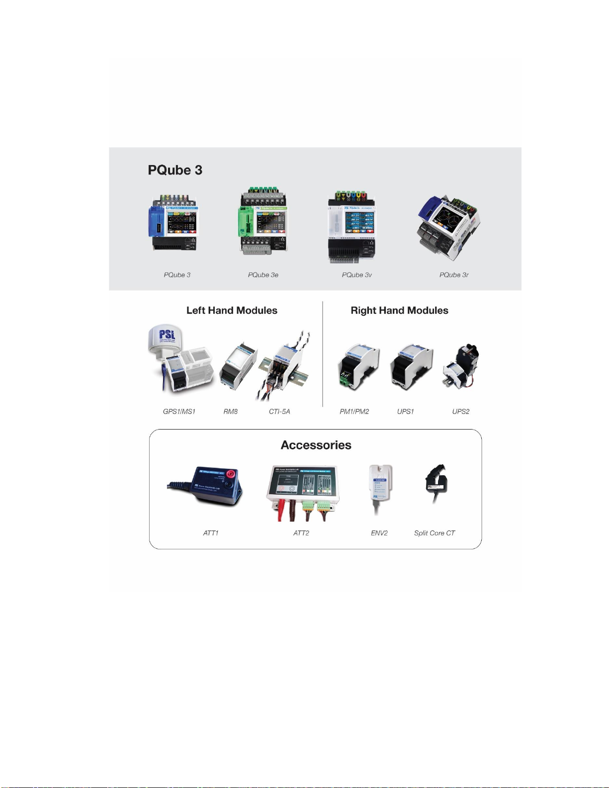
1.3 Overview of PQube3 models and modules
PQube 3 comes in four versions:
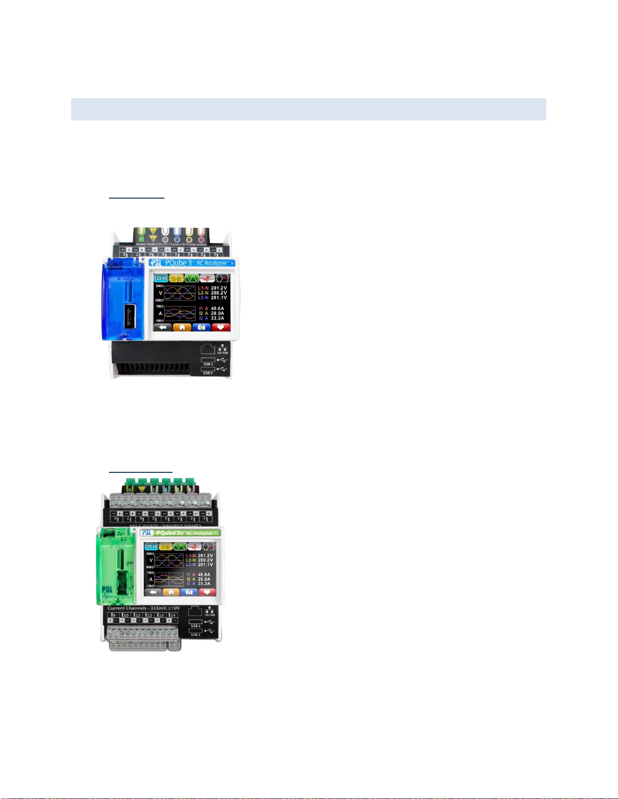
1.3.1 PQube 3
The PQube 3 is the most popular model (more details below)
in the family. It is easy to setup and comes from the factory
with a default setup so you can “plug and go” for most
installations. It auto-detects the mains frequency, wiring
configuration and nominal voltage. You can connect directly to
up to 600 volts (nominal) and the device computes 4-quadrant
ANSI Class 0.2 revenue–grade energy on eight single-phase
channels and is certified for Class A power quality according to
IEC 61000-4-30 Ed3
The PQube 3 holds years of data and thousands of events via
32 GB of internal flash memory.
1.3.2 PQube 3e
PQube 3e is identical to the PQube 3 and adds more metering
channels. You can connect up to 14 energy metering channels –
these can be configured in any combination of four three-phase
loads or 14 single-phase loads. You can quantify energy costs with
revenue-grade-accuracy ANSI Class 0.2 including CTs and
simultaneously utilize the PQube 3e’s advanced Class A power
quality monitoring.
Setup is identical to the PQube 3: Configure the additional channels
at installation using the same Configurator tool as the PQube 3.
Page 9
PQube 3 Installation Manual
Page 9 of 48
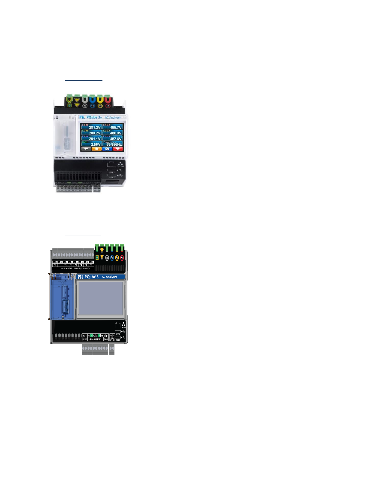
1.3.3 PQube 3v
If you are focusing purely on voltage compliance the PQube 3v is the
best value: It connects the mains voltage directly at up to 600VAC
nominal.
The unit does a great job verifying electricity delivered at the point of
common coupling (PCC), as well as diagnosing equipment
malfunctions. It monitors AC power (or DC voltage), but you can also
monitor process parameters like speed or flow, by attaching sensors
to the analog AC/DC channels.
You get the same ultra-precise results delivered immediately to your
inbox.
Setup is identical to the PQube 3: You only need configure voltage
values and the unit uses the same easy-to-use Configurator tool.
1.3.4 PQube 3r
PQube 3r identical to PQube 3 and is your best choice for protecting
sensitive processes that require recovery actions because of specific
power disturbances. For example, a production line running a
sensitive process where tools must be reset to a known state or the
line must be properly shut down before the production process is
restarted.
It features 3 additional trigger output relays to monitor sag/swells/
interruptions, wave shape changes, high frequency impulses,
over/inrush current.
Setup is identical to the PQube 3and uses the same easy-to-use
Configurator tool.
Page 10

PQube 3 Installation Manual
Page 10 of 48
1.3.5 Modules and Accessories
Each PQube 3 comes standard with the following features:
Three AC mains voltage channels
Eight current channels (for CTs with 0.333V secondary), 14 channels for PQube 3e
Four analog input channels for additional signals (for example, the output of a power
supply)
One digital input channel (monitor the state of an interlock switch)
One signal output relay (notify your PLC that an event has occurred)
Power supply input rated for 24VAC or 24-48VDC
One 10/100 Ethernet port (PoE compatible!)
One Hi-speed USB 2.0 port (for USB drive or ENV2 environmental probe)
Two standard USB 1.0 ports (for ENV2 environmental probes)
Full color touchscreen
32GB internal memory
One 16GB microSD card
One USB drive included with each PQube 3 (contains manual, quickstart guide, setup file,
Configurator program, Report Writer program)
Several types of modules and accessories are available including:
AC/DC Interface: VAT1, ATT1, and ATT2.
Power Supply and Backup: UPS1, UPS2, and UPS3.
Time and Synchronization: MPS1 and GPS.
Relay Extensions: RM8.
Environment Sensors: ENV 2.
Current Interface for 1A/5A CT Secondaries: CT-1A and CT-5A.
To choose modules for your application, you need to ask yourself:
Do I need to power my PQube 3 from 100~240Vac (50/60/400 Hz) and if so do I need battery
backup in the event of a power outage? See Power Supply and Backup Modules
Do I need current inputs to measure the 1A or 5A secondary of a CT at ANSI Class 0.2 or IEC
62053-22 Class 0.2S revenue energy accuracy? See CTI Series CT Interface Modules
Do I need ultra-precise GPS timestamps on your data? See Time and Sync Modules
Do I want to record the environmental conditions such as temperature, humidity, pressure,
or acceleration? See Environmental Sensor
Page 11
PQube 3 Installation Manual
Page 11 of 48
Below is an overview of the PQube 3 family and accessories. The left hand connected modules
include the GPS, relay module and those for measuring the secondary of current transformers.
The right hand modules are power supply and power backup. The accessories include various
attenuators, split core CTs and environmental probes.
Page 12
PQube 3 Installation Manual
Page 12 of 48
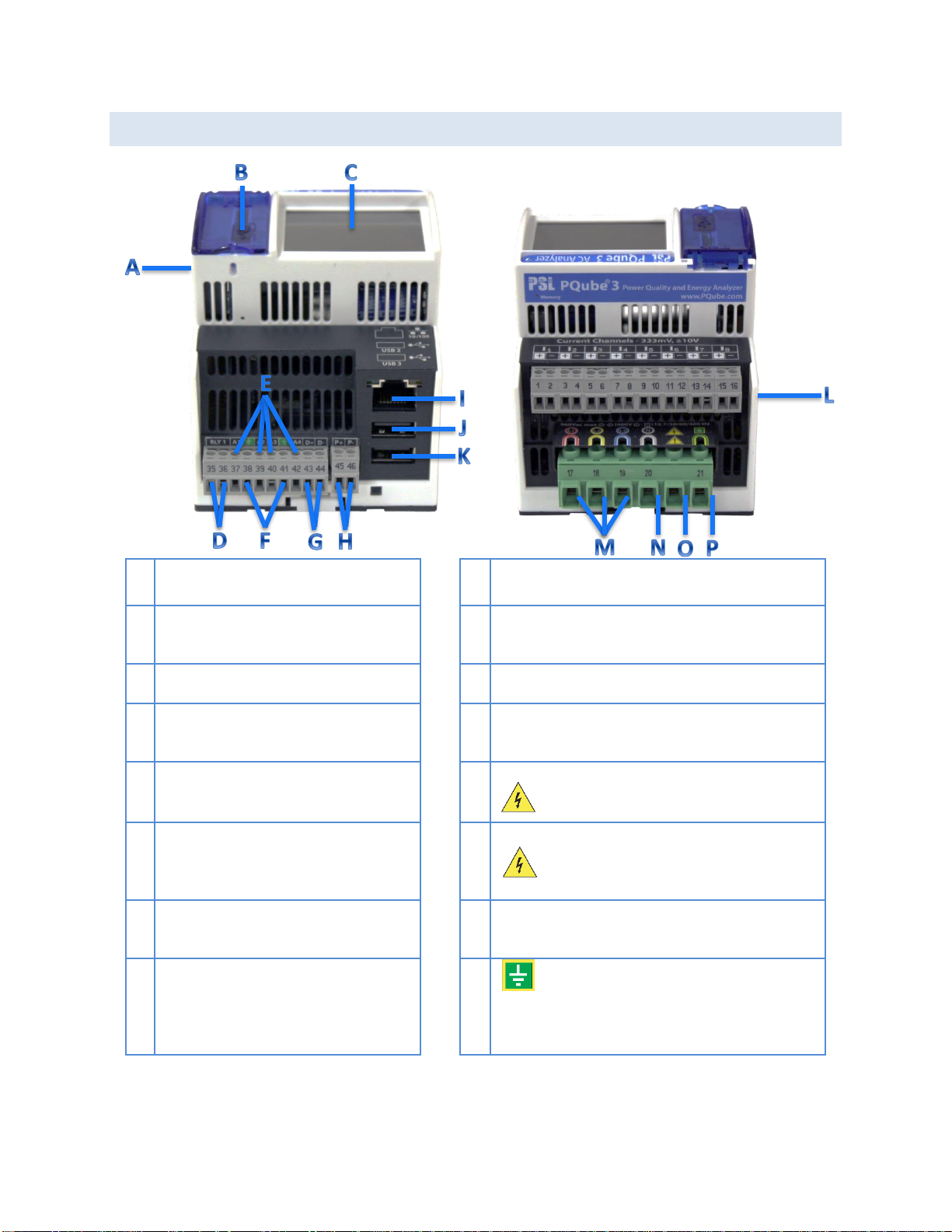
1.4 Overview of PQube 3 Ports, Connections and Controls
A
Coin-cell battery (keeps real time clock
alive when instrument power is lost)
I
10/100 Ethernet RJ-45 port. 48V PoE compatible.
B
USB-1 High-Speed USB 2.0 port for USB
hard drives and adjacent microSD card
slot (format using FAT32 filesystem)
J
USB-2 Standard USB 1.0 port for use ONLY with ENV2
environmental probes.
C
Touchscreen display
K USB-3 Standard USB 1.0 port for use ONLY with ENV2
environmental probes.
D
Signal relay output. Normally closed
during recording mode. Opens ½ cycle
after event or device shutdown.
L
Current transformer inputs – nominal 0.333V RMS
(LOW range) or ±10Vpk (HIGH range)
E
Analog inputs. Maximum ±60VDC or
33VAC to earth. Can be used as
differential inputs.
M
L1, L2, L3 voltage inputs. See page 23 for
maximum voltage ratings.
F
Earth – functional. Use as a reference
point for analog inputs (not needed if
using analog channels in differential
mode).
N
Neutral terminal – optional depending on
your power configuration
G
Digital input. Wetted with 2.4V at 3
microamps. 1.5-volt threshold. 60-volt
tolerant.
O
Not connected.
H
Power supply input. 24VAC, or 24VDC to
48VDC (either polarity) nominal. 20VA
max.
P
Earth – functional. Used as the reference
point for voltage measurements.
IMPORTANT: this terminal must be properly
connected to ground for safety, accuracy, and
reliability.
Page 13

PQube 3 Installation Manual
Page 13 of 48
1.5 Choosing Modules
1.5.1 Power your PQube 3 from 100~240Vac (PM1/PM2)
If you have 24~48Vdc or 24Vac, you can use your PQube 3’s internal power
supply (just connect the voltage to the power supply screw terminal blocks).
If you need to power your PQube 3 from 100~240Vac, you’ll need the plug-
in PM1 or PM2 Power Manager module.
The PM2 module also includes a 24VDC auxiliary output so you can power small
accessories (up to 5W) like LEDs or fans.
1.5.2 Backup your PQube 3 during a power outage (UPS1/UPS2/UPS3)
UPS1
Connect the UPS1 Battery Backup module to your PQube 3 to provide
up to 30 minutes of backup power during a power outage. It can be
used with or without a PM1 or PM2 module.
UPS2 and UPS3
Extended autonomy models are
available: The UPS2 backup module
provides extended power backup (up to
three hours) controlling up to three
PSL XB1 lead acid battery packs (60
min/pack). The UPS3 is identical and
also includes outputs to backup 5 watts
of accessories. Both units offer a wide
temperature range (25°C~60°C) for
severe environments such as
shipboard.
Page 14
PQube 3 Installation Manual
Page 14 of 48
1.5.3 Measure currents from secondary of current transformers (CTI-
1A/CTI-5A)
Your PQube 3 comes standard with 8 current
channels which are compatible with CTs with
0.333V secondary.
But if you need to measure CTs with 1A or 5A
secondary wires for your application, use the CTI
Current Transformer Input module.
There are two versions; one with 1A input and
one with 5A input. Use the CTI module that
matches the secondary rating of your external
CTs.
There are four current inputs per module. Your
PQube 3 can accommodate up to two CTI
modules.
Use this module if your application requires ANSI
C12.20 Class 0.2 or IEC 62052-22 Class 0.2S
revenue grade accuracy.
1.5.4 Three Phase AC/Dual DC Voltage Attenuator
The perfect solution for monitoring two sets of three-phase AC voltages
such as the primary and secondary side of transformers or the input and
output of a three–phase UPS. The unit could be used in a data center to
monitor two HVDC channels like the input and output of 480VAC to 380
VDC rectifiers.
Page 15
PQube 3 Installation Manual
Page 15 of 48
1.5.5 Relay Extension Module for load shedding (RM8)
You can now turn your PQube 3 into a powerful controller, and
command the shedding of loads to protect your main
distribution circuit from tripping.
The RM8 extension relay module snaps easily to your PQube3
(also PQube 3e) and its 8 relays are fully programmable.
This allows you to customize your load shedding scheme by
assigning incremental thresholds, or by applying the scheme to
protect up to 4 circuits. And the PQube3 power Analyzer
measures, reports in real time and records the power, VA, VARs
and Power Factor of all the circuits monitored
1.5.6 Measure Environmental Conditions (ENV2)
The ENV2 environmental probe allows your PQube 3 to measure ambient temperature, humidity,
pressure.
It also includes an accelerometer to measure shock and vibration, a thermocouple input for wide
temperature ranges, and a solar irradiation input.
Connect up to 2 probes to your PQube 3 using a microUSB to USB cable.
You can use a USB cable with a length of up to 15ft /5 meters.
Page 16

PQube 3 Installation Manual
Page 16 of 48
1.5.7 Synchronize your PQube 3 clock to GPS time
Your PQube 3 can synchronize its time clock to GPS, which provides better than 1 microsecond
accuracy. This is useful for Class A measurements, or if you need to make phasor measurements
with a microPMU.
MS1-GPS1
The MS1 module interfaces with the GPS1 receiver to provide your
PQube 3 with ultra-precise time, (no drift) time stamping for power
quality events.
The GPS1 receiver locks onto GPS satellites in
the sky to provide your PQube 3 with ultraprecise GPS timing. It is designed to be
weather-resistant and you can install it outside
using optional mounting hardware. It has
600V functional isolation at both ends of the
cable for safety.
Connect the GPS1 receiver to your MS1 module using the included cable. You can extend the cable
up to 25 meters using a female-female RJ-45 coupler and standard CAT5E cable.
Page 17

PQube 3 Installation Manual
Page 17 of 48
2 Installing Your PQube 3
2.1 Unpacking your PQube 3
Verify that your package contents are complete:
1 PQube 3
1 USB thumb drive (contains manual, quickstart guide, setup file, Configurator program, Report
Writer program)
1 six pole Voltage connector (mains voltage)
8 two pole connectors (current inputs)
1 two pole connector (power supply)
1 ten pole connector (for analog channels, digital input, relay output)
Note:
PQube 3e comes with an additional 6 two pole connectors (additional current inputs)
PQube 3v is not equipped with current input connectors
PQube 3r comes with an additional set of 3 three pole connectors (additional 3 relays)
2.2 Installation
2.2.1 Disconnect mains prior to servicing
IMPORTANT: Your PQube 3 must be installed only by qualified personnel for electrical installations.
Always disconnect all mains connections, and verify disconnections, prior to servicing.
In the United States and Canada, the equipment installation shall meet ANSI/NFPA 70, NEC, with CSA
C22.1, CEC, Part I or with both as appropriate. In other countries, follow all local installation
requirements and regulations.
2.2.2 Mount your PQube 3 properly and securely
Your PQube 3, and its optional modules, are designed to be mounted on an industry-standard 35mm
DIN rail as rack- or panel-mounted equipment.
Page 18

PQube 3 Installation Manual
Page 18 of 48
MS1 module on left
side of PQube 3
PQube 3 (main module)
PM1/PM2 Module
on right side of
PQube 3
UPS1 Module
on far right
side
Example installation:
2.2.3 Include overcurrent protection and a disconnecting device
An external overcurrent protection device, such as a fuse or a circuit breaker, must be installed on
each mains connection. The device shall be UL Listed, branch circuit type overcurrent protector.
You should consult a qualified electrician to determine the overcurrent protection installation.
Your PQube 3 can share the overcurrent protection device with other loads.
An operator-activated disconnecting device, such as a switch or a circuit breaker, must be installed
on the mains connections. This device must be clearly marked as the disconnecting device for your
PQube 3, and must be marked to indicate the disconnection function. Do not install your PQube 3 in
such a way that it becomes difficult to operate this disconnecting device. The disconnecting device
must not disconnect the earth connection. The disconnecting device should be installed near your
PQube 3, within easy reach of the operator.
2.2.4 Protect the operator from the hazardous terminals
IMPORTANT: All high voltage parts must be covered, including the AC power to your PQube 3.
Install your PQube 3 so that all of the screw terminal blocks are not ACCESSIBLE1 to the operator. Your
PQube 3 can also be installed without a cover if installed in a lockable IUL 508 control panel.
1
Accessible, as defined in UL 61010-1, means able to be touched with a standard test finger or test pin, when used as specified
in UL61010-1 6.2.
Page 19

PQube 3 Installation Manual
Page 19 of 48
The operator must be protected from the hazardous screw terminal blocks by a barrier. The screw terminal blocks must be
made “not ACCESSIBLE”, as defined in UL /IEC 61010-1 6.2, using an enclosure or barrier that meets the rigidity requirements of
UL /IEC 61010-1 8.1 and that requires a tool to remove.
If you choose to install your PQube 3 in an enclosure, select a UL-listed enclosure that is appropriate for the purpose. If you plan
to use an enclosure of this type, you should review its mechanical compatibility with any optional features of your PQube 3 that
you plan to use: optional USB connections, optional temperature-humidity probes, etc.
2.2.5 Connect your PQube 3 to the power supply
Your PQube 3 can take its operating power from four different sources:
24VAC or ±24–48VDC power supply terminals on PQube 3
Power over Ethernet (PoE)
Optional PM1/PM2 Power Supply module
Rechargeable UPS module (automatically provides up to 30 minutes of battery backup
when the main power supply source drops out)
Page 20

PQube 3 Installation Manual
Page 20 of 48
PQube 3 power supply terminals
The instrument power terminals (45 and 46) on the front of your PQube 3 must be connected to
24VAC (±20%) or 24–48VDC (±20%), supplied by a certified isolating power supply.
WARNING: Applying voltages outside of this range can
cause permanent damage to your PQube 3.
Polarity does not matter. Also, your PQube 3 provides a
minimum of 150V of transformer-based isolation
between these terminals and all other terminals,
eliminating any problems with ground loops.
Power over Ethernet (PoE)
Plug in an Ethernet cable leading to a 48V PoE source (PoE switch/hub/router or PoE injector).
If no other power sources are available, your PQube 3 will request power from the PoE switch.
If your PQube 3 is already powered from another source (24V power supply or PM1/PM2 power
supply module, for example) then it will not request power from the PoE switch when you plug it in.
PM1 or PM2 Power Supply Module
The PM1 or PM2 module accepts a range of 100~240VAC, 50/60/400Hz. It snaps into the right side
of your PQube 3. This module is ideal for applications where 24-48VDC, 24VAC, and PoE are not
available. Make sure your AC source can supply at least 20W.
PM2 front view –
24VDC output terminals
PM1/PM2 rear view -
100~240VAC input terminals
PM1 top view -
100~240VAC input terminals
On the PM2 module, 24VDC outputs are available on the 8-pin terminal block for powering external
accessories including DC Hall Effect sensors and indication LEDs. The first pair of terminals labeled
“Switched 24Vdc” can be toggled on and off in software. The other three pairs are tied together
internally. The total combined power output is 5W. This is enough to power one additional PQube
3.
UPS1 Module
Plug the UPS1 module on the right side of your PQube 3 or PM1/PM2 module. This module is always
the outermost module on the right side.
Page 21

PQube 3 Installation Manual
Page 21 of 48
By default, the UPS timer interval is 5 minutes. However, you can choose the operating duration by
writing a value in your Setup.ini file. The value can be set from 3 to 30 minutes. This guarantees that
there will be enough charge in the battery to record several successive power interruptions.
As the lithium ion battery inside the module ages, its capacity will decline. Depending on operating
conditions and requirements, it may be necessary to replace your UPS1 Module every 3 to 5 years
or 500 cycles, whichever comes first.
UPS 2 and UPS 3 allow for the addition of external batteries for up to 3 hours of battery life.
Maximum Load and Temperature Ratings
Your PQube 3 is rated for 65°C maximum ambient temperature under normal conditions when
installed according to the procedures set forth in this manual.
However, when loading the PM2 module’s 24V auxiliary circuit with 5W, the maximum ambient
temperature is derated to 55°C.
Power Source
Product
Configuration
Auxiliary
24VDC load
Maximum USB
Load
Maximum Load on Relay
Outputs
Maximum Ambient
Temperature
Instrument
Power
Terminals
PQube 3, MS1,
GPS1
No load
USB1 1.5W
USB2 0.5W
USB3 0.5W
RLY1, RLY2, RLY3, RLY4
loaded with 30VDC/30VAC,
300mA max
65°C
PM1 AC Input
Terminals
PQube 3, PM1,
UPS1
5.15W max
USB1 0.3W
USB2 0.1W
USB3 0.1W
RLY1 loaded with
30VDC/30VAC, 300mA max
55°C
PM1 AC Input
Terminals
PQube 3, PM1,
UPS1, MS1, GPS1
No load
USB1 0.3W
USB2 0.1W
USB3 0.1W
RLY1 loaded with
30VDC/30VAC, 300mA max
65°C
Page 22

PQube 3 Installation Manual
Page 22 of 48
2.2.6 Connecting the wires
Observe the wire size specifications and limitations. All conductors must be stranded copper. All
conductors and insulation systems and crimped devices must be appropriate for the application. PSL
recommends crimped ferrules on stranded wire. Tighten the screws on the high voltage terminal
block to 0,5 newton-meters (5 inch-pounds) of torque. Observe all voltage ratings and limits.
For connections, PSL recommends wire ferrules for stranded wire, such as Panduit F77 series, for example Panduit F77-6-M.
Figure 1: Your PQube meets all IEC requirements for highfrequency emissions and susceptibility, both conducted
and radiated. For further protection, you can use clamp-on
ferrites on signal cables to minimize radio-frequency
emissions. For example, these are Panasonic
KRCBC160928B and KRCBC130714B.
Figure 2: To minimize emissions with the optional PM1
Power Supply module, optionally use a shielded power
conductor.
Conductor characteristics
Connection
Minimum wire size
Maximum wire
size
Limitations and remarks
Comply with all local safety and installation
requirements and regulations.
PQube 3 terminals
L1, L2, L3, N
20AWG (0,52 mm2)
14 AWG (2.1mm2)
Min 600V UL-recognized insulation system required.
These terminals require less than 0,01 amps. Connection
to N (15) is optional. For single phase monitoring,
connect either L1-N or L1-L2 as appropriate for the mains
configuration.
PQube 3 Earth
terminal
20AWG (0,52 mm2)
14 AWG (2.1mm2)
Connect this terminal to a suitable earth connection. For
proper PQube operation, you must connect this terminal
to earth. It is used as a measurement reference, and as a
reference for your PQube’s low voltage circuits.
Optional
PQube 3 terminals
20AWG (0,52 mm2)
14 AWG (2.1mm2)
Min 600V UL-recognized insulation system required.
Wire size must be adequate for relay contact load. These
terminals rated at 30 VAC max, 60 Vdc max, 2 amps max.
All other terminals
20AWG (0,52 mm2)
14 AWG (2.1mm2)
Min 600V UL-recognized insulation system required.
PM1 AC Input
terminals
20AWG (0,52 mm2)
14 AWG (2.1mm2)
Min 600V UL-recognized insulation system required.
Shielded cable recommended for minimizing emissions.
PM1 DC Output
terminals
20AWG (0,52 mm2)
14 AWG (2.1mm2)
Min 600V UL-recognized insulation system required
Page 23

PQube 3 Installation Manual
Page 23 of 48
Maximum voltages
Connection
Measurement
Category
Maximum
current
Limitations and remarks
PQube 3 terminals
L1, L2, L3, N
600 Vrms, CAT III
Corresponds to 480V L-N / 830V L-L max for 3-phase, 4wire Wye/Star systems.
Corresponds to 600V L-L max for 3-phase, 3-wire Delta
systems.
Corresponds to 480V L-L max for 1-phase, 2-wire Single
Phase systems.
Corresponds to 480V L-N / 960V L-L max for Split-SinglePhase, 3-wire systems.
All voltage channels must be covered after installation.
300 Vrms, CAT IV
Corresponds to 277 L-N / 480V L-L max for 3-phase, 4wire Wye/Star systems.
Corresponds to 480V L-L max for 3-phase, 3-wire Delta
systems.
Corresponds to 240V L-L max for 1-phase, 2-wire Single
Phase systems.
Corresponds to 240V L-N / 480V L-L max for Split-SinglePhase, 3-wire systems.
All voltage channels must be covered after installation.
PQube 3 Earth terminal
N/A
Optional PQube 3 RLY
terminals
30 Vrms or 60 Vdc
0.3A
All other PQube 3
terminals
30 Vrms or 60 Vdc
PM1 AC input terminals
240 Vrms, CAT II
Rated for Single-Phase 100~240VAC max. AC voltage
input terminal must be covered after installation.
PM1 DC output
terminals
24 VDC
0.42A
10W maximum output
USB1 Input
5VDC
0.2A
USB2 and USB3
5VDC
0.1A
Note: “CAT III” means Measurement Category III as defined in UL / IEC 61010-1: “Measurement category III is for measurements
performed in the building installation…. Examples are measurements on distribution boards, circuit-breakers, wiring, including
cables, bus-bars, junction boxes, switches, socket-outlets in the fixed installation, and equipment for industrial use…”
“CAT IV” means Measurement Category IV as defined in UL / IEC 61010-1: “measurements performed at the source of the lowvoltage installation…. Examples are electricity meters and measurements on primary overcurrent protection devices and ripple
control units.”
Page 24

PQube 3 Installation Manual
Page 24 of 48
2.2.7 Connect mains AC voltage wires
The large high voltage terminal block on the back of your PQube 3 is removable. Refer to the wiring
diagrams on page 32 and use the appropriate wiring scheme for your power configuration.
IMPORTANT: Don’t forget to install the Earth conductor. Your PQube 3 relies on the Earth conductor
for safety, reliability, and accuracy.
You must apply at least 30VAC to these terminals before your PQube 3 will begin recording.
Page 25

PQube 3 Installation Manual
Page 25 of 48
PQube 3
PM1
PQube 3
PM1
UPS1
2.2.8 Protect antenna terminals from lightning
If you install an antenna in an outdoor location where it may be exposed to lightning, you must
include a properly installed UL-497C-listed lightning protection device on the antenna cable and the
antenna must be reliably earthed. Follow all local installation safety requirements and regulations.
2.2.9 Installing Your PM1 Power Supply Module
The optional PM2 Power Supply Module connects to the right side of your PQube 3; just snap it in.
It accepts any 50/60/400 Hz single-phase input between 100Vac and 240Vac nominal. Verify that
you are connecting the line and neutral wires to the correct terminals on the module.
2.2.10 Installing Your UPS Module
The UPS1 Module provides backup power to your PQube 3 in the event of complete loss of
instrument power. Plug it into the right-side of your PQube 3. If using a PM1 Power Supply Module,
plug the UPS module into the right side of the PM1/PM2 module. The lithium-ion battery pack can
provide power between 3 and 30 minutes (user-configurable).
If more power duration is required UPS 2 and 3 with optional battery packs can be used.
Page 26

PQube 3 Installation Manual
Page 26 of 48
2.2.11 Installing Split Core Current Transformers (CTs)
Your PQube 3 records AC current by measuring the secondary circuit of a current transformer (CT).
When installing current transformers, it is important to match the phases to the voltage inputs and
current input (connect the L1 voltage input and the L1 current sensor to the same conductor). This
is necessary for correct power and energy calculations.
Instructions for setting your CT ratio can be found on page 41.
IMPORTANT: You must only use UL listed energy monitoring current transformers with your PQube
3.
A note on choosing the appropriate range of CT’s for your application:
If the PQube 3 is installed to monitor power and load, the nominal rated
current of the CT should be the most common load current throughout the
consumption period (e.g. work days). Your PQube 3 makes current
measurements with a Crest Factor of 3.5. This means that your PQube 3 can
measure instantaneous currents up to 350% of the nominal rated current (for
example, if you have selected a 300-amp current transformer, your PQube 3
will accurately measure up to ±1050 amps instantaneous). This is a very useful
feature when dealing with inrush currents, and currents with high harmonic
contents.
If the PQube 3 is installed to troubleshoot circuit breaker trip operation, the
nominal rated current should be selected closer to the trip settings. In all cases
the PQube crest factor of 3.5 provides a margin to capture properly the peak
currents.
Note: you can skip this chapter if you are
installing a PQube 3v (voltage monitor)
Page 27

PQube 3 Installation Manual
Page 27 of 48
Note:
Calibrated to match the input impedance of your PQube 3’s current input channels, and each CT
comes with its own NIST-Traceable calibration certificate and table which you can upload to your
PQube 3.
PSL Ultra-Precise CTs are UL listed and utilize a 0.333V secondary to match your PQube 3’s current
input terminals. A burden resistor is built into the CT so you do not need to worry about hazardous
open circuit voltages.
You can see the list of available PSL Ultra-Precise CTs for your PQube 3 here:
https://www.powerstandards.com/?product=kits-modules-accessories/current-sensors
You can look up the calibration certificate for your CTs here:
https://www.powerstandards.com/?product=pqube-3/certificates
Note: PSL Ultra-Precise CTs:
PSL Ultra-Precise CTs are specifically designed for your
PQube 3. Ultra-Precise calibrated shielded split-core CT are
specifically designed to meet demanding accuracy
application with accuracy on both current amplitude AND
current angle accuracy.
The PSL Ultra-Precise CT’s exceed the most demand
standard: ANSI C12.20 Class 0.2 revenue grade *
This is important if you need to measure high-order current
harmonics or if you need revenue-grade accuracy for your
application.
Page 28

PQube 3 Installation Manual
Page 28 of 48
Installing Split Core CTs with 0.333V secondary
Your PQube 3 comes standard with 8 current input channels, which are typically used to measure
L1, L2, L3, N, E, plus 3 additional single-phase channels. The current channels on your PQube 3 are
rated for 0.333V nominal input, and they are designed to be used with CTs with 0.333V secondary.
For PSL CTs, white wires are positive and black wires are
negative.
If using PSL Ultra-Precise CTs with the shielded secondary
wires, red is positive and black is negative. Connect the shield
conductor to ground. If using another manufacturer’s CTs,
verify which wires are positive and negative before installing
them.
Clamp the CT around the conductor. For all PSL CTs, the label faces towards the source.
.
FCT-XX-3000A Flexible Current Sensor Installing Split Core CTs with 0.333V
secondary
The flexible AC current sensors (Rogowski coils) are perfect for applications where limited space
makes installation of traditional current transformers difficult or impossible. Their pliable split-core
design allows you to easily clamp around cables or bus bars
Plugs directly into your PQube 3 – built-in integration, but must be configured in setup.ini.
Flexible, IP 65 weather resistant loop
Four-meter cable, shielded for noise immunity
UL approved, RoHS, and WEEE compliant
From
source
To load
The arrow
must face
the source
Page 29

PQube 3 Installation Manual
Page 29 of 48
Nominal 30 A to 3000 A measurement range
Typical amplitude accuracy: ±0.5% rdg
Typical angle accuracy: ±1 deg
No magnetic hysteresis (saturation or non-linearity)
Calibrated to match PQube 3 impedance
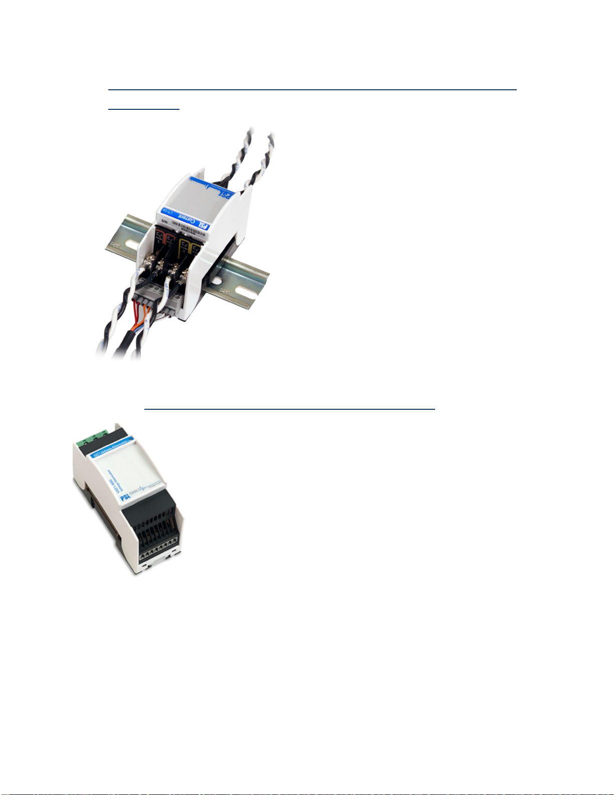
Installing CTs at the secondary of measuring current transformers (1A or 5A
secondary)
If you will be monitoring the 1A or 5A secondary of existing metering CTs, you will need to use the CTI-1A
or the CTI-5A module. They have 1A and 5A nominal inputs, respectively.
The CTI module inputs are installed in series with your 1A or 5A secondary circuit. The terminal block on
your CTI module is connected to the 0.333V current input channels on your PQube 3. Each CTI module
includes 4 current channels, so you can use up to 2 CTI modules per PQube 3.
WARNING: When installing CTs with 1A or 5A secondaries, take extra precautions to ensure
that an open circuit does not develop on the secondary wires. Shorting blocks are typically
used to avoid the possibility of an open circuit during installation. CTs must be installed only
by qualified personnel for electrical installations.
Page 30

PQube 3 Installation Manual
Page 30 of 48
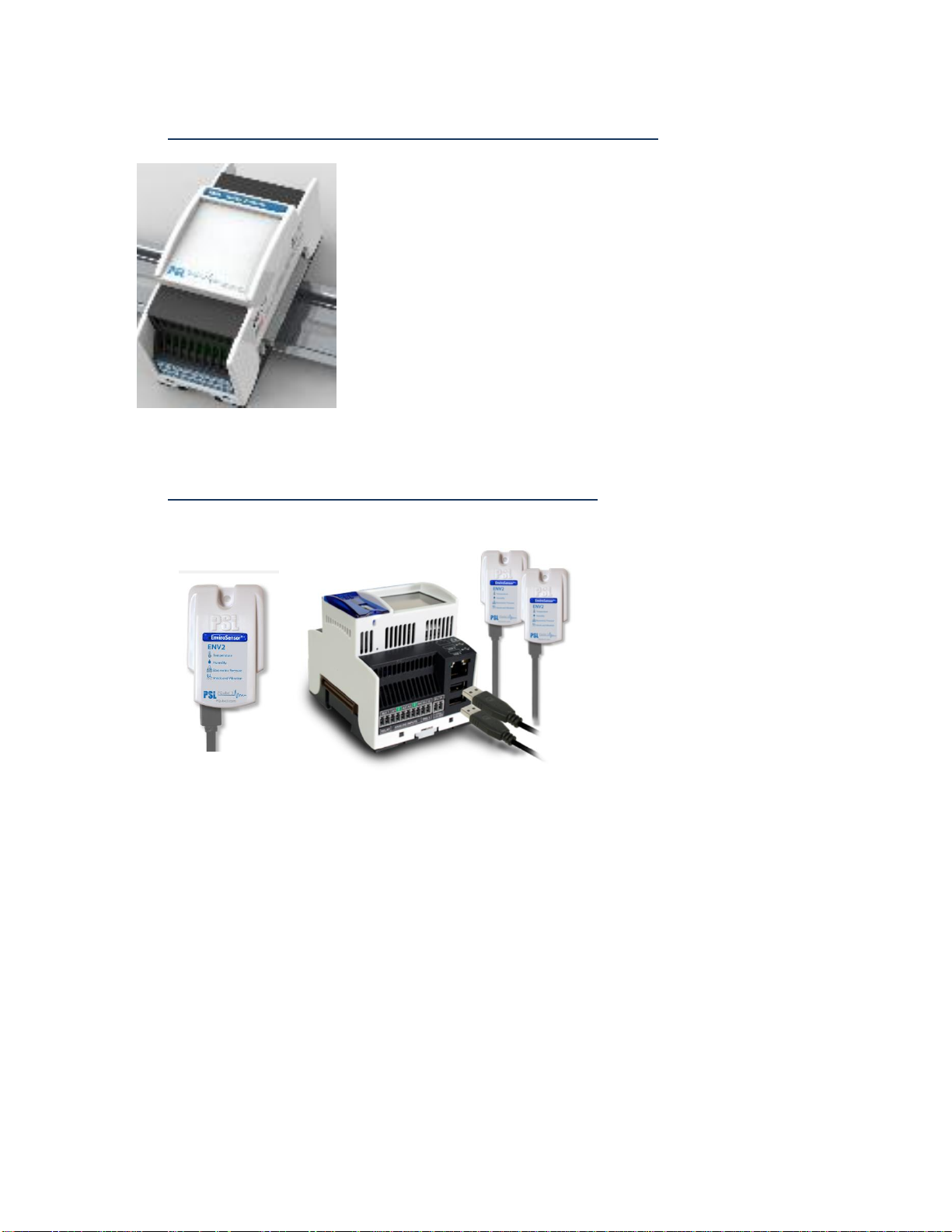
2.2.12 Connecting the ENV2 environmental probes
ENV2 probes are interfaced through a USB cable. Insert the USB connector into the USB-2 and
USB-3 slots of the PQube 3. You can connect up to 2 probes to your PQube 3.
Note: if necessary, the probe can be connected to the front USB-1 slot, but you cannot extract
data over USB while the probe is occupying this port.
You can verify the proper operation of the environmental probe by checking the meter on the
screen (see Chapter “Operation” - touch screen - meters).
1A or 5A vs. 0.333V secondary, what’s the difference?
Most current transformers are designed to have 1A or 5A of current flowing
through the secondary circuit while full rated current is flowing through the
primary circuit.
While installing CTs with 1A or 5A secondary, it is imperative that an open
circuit does not develop in the secondary. If an open circuit develops while
current is flowing through the primary of the CT, a very hazardous open circuit
voltage (OCV) will develop across the opening. In this condition, typical OCV
values can range from hundreds to thousands of volts.
For this reason, PSL offers CTs exclusively with 0.333V secondary. Our CTs
include a built-in burden resistor in the secondary circuit so that the current
always has a path to flow through. The resistor value is calibrated and tuned
to achieve a 0.333V drop across the resistor at full rated current. This 0.333V
signal can then be measured using the 2 wires coming out of the CT.
Page 31

PQube 3 Installation Manual
Page 31 of 48
2.2.13 Installing Your MS1 Sync Module (if GPS synchronization needed)
The optional MS1 Sync Module connects to the left side of your PQube 3; just snap it in. Connect
the module before supplying power to your PQube 3. The MS1 Sync Module interfaces with the
PSL GPS1 module using a special 8-pin cable at the MS1 module and an RJ45 connection at the
GPS1 receiver.
See the PQube 3 reference manual for the description of the MS1- GPS1-cable
IMPORTANT: Do not connect the RJ-45 plug of your GPS cable into a network switch or router.
It will damage your networking equipment.
Page 32

PQube 3 Installation Manual
Page 32 of 48
3 Wiring Diagrams
3.1 Wiring diagram for PQube 3v
PQube 3v measures voltage
only so connections DO NOT
include CTs
Page 33

PQube 3 Installation Manual
Page 33 of 48
3.2 Wiring Diagrams (PQube 3, PQube 3e, PQube 3r)
3.2.1 Single Phase L1-L2
Page 34

PQube 3 Installation Manual
Page 34 of 48
3.2.2 Single Split Phase
3.2.3 Delta – 3 CTs
Page 35

PQube 3 Installation Manual
Page 35 of 48
3.2.4 Delta – 2 CTs (PQube 3 calculates current on remaining channel)
3.2.5 Wye/Star
Page 36

PQube 3 Installation Manual
Page 36 of 48
3.2.6 Measuring Neutral Current (applies to any power configuration
with Neutral)
3.2.7 Measuring Earth Current (applies to any power configuration)
Page 37

PQube 3 Installation Manual
Page 37 of 48
3.2.8 Measuring Net Earth Current – Delta
3.2.9 Measuring Net Earth Current – Wye/Star
Page 38

PQube 3 Installation Manual
Page 38 of 48
4 Configuring Your PQube 3
4.1 Using the Configurator
Your PQube 3 comes with a factory default configuration. This configuration is an ASCII file
(setup.ini).
To customize your individual configuration, you can edit it using the PQube 3 Configurator
program. This graphical editing utility is simple to use and will help avoid mistakes and possible
conflicts across various dependent parameters.
You could use (but not recommended) a text editor like Notepad to edit the setup.in.
You can download the PQube 3 Configurator program for free here:
https://www.powerstandards.com/download-center/pqube-3-3e/#5
After you’ve made your changes, save the file as Setup.ini and upload it back to your PQube 3 via
email, web, FTP, and it will automatically reboot and load the new settings on startup. You can also
copy your new Setup file onto a USB drive or microSD card and insert it directly into your PQube 3.
After detecting the new Setup file, your PQube 3 will ask you to reboot so it can load the new settings.
Notes:
The factory-default setup file is identical to the USB drive that shipped with your PQube 3.
Page 39

PQube 3 Installation Manual
Page 39 of 48
If you are installing a PQube 3 which has been used previously, you may want to use a copy
of that configuration, and then edit it with the Configurator.
You can retrieve your PQube 3’s existing setup file via USB stick locally, or remotely via
email, web pages, or FTP.
Page 40

PQube 3 Installation Manual
Page 40 of 48
4.2 Initial Device Setup
Your PQube 3 will work right out of the box. Once your PQube 3 has been installed, connected to the
monitoring circuit, and powered on, it will begin recording data immediately. The default settings will
work for most applications. Note: For Delta Configuration (3 phases, no neutral)
4.2.1 Set Your Potential Transformer (PT) Ratio
If you monitor voltages above 960Vac Phase-to-Phase (480Vac Phase-to-Earth), you need to
interface to the secondary of a potential transformer (which steps down the voltage to a level
compatible with your PQube 3 ).
You then need to define the PT ratio in the configuration, so that your PQube 3 reports the actual
primary voltage.
For example, to use your PQube 3 on a 24 kV distribution system, and use a secondary voltage of
240V, you need to set a 100:1 PT ratio.
In the Configurator, set the PT ratio to 24000:240 or 100:1. You will also need to set your nominal
voltage using the primary voltage of your PT. Even though your PQube 3 has 240V applied to its
mains AC voltage terminals, you need to set the nominal voltage to 24000.
For the PQube 3v ONLY the voltage settings are set, there are no current inputs.
Page 41

PQube 3 Installation Manual
Page 41 of 48
Note: you can skip this chapter if you are
installing a PQube 3v (voltage monitor)
4.2.2 Set Your Current Transformer (CT) Ratio
If you are using CTs with 0.333V secondary
To set the CT ratio, simply enter the primary current and secondary voltage into your CT ratio. For
example, if you have a current transformer rated at 300 amps, with 0.333V secondary, then you
would set your CT ratio to 300:0.333. The value in the Current Transformer Ratio field is applied to
the L1, L2, and L3 current channels.
If you are using CTs with 1A or 5A secondary
Use the CTI-1A or CTI-5A modules are designed to accept the 1A or 5A secondary of metering CTs.
The CTI-1A module has a ratio of 1A:0.333V. The CTI-5A module has a ratio of 5A:0.333V.
To calculate your CT ratio, multiply the ratio of your metering CT by the ratio of your CTI module.
CT Ratio
CTI Module
CT Ratio Calculation
CT Ratio in Setup File
Example 1
300A:5A
CTI-5A module
300𝐴
5𝐴
×
5𝐴
0.333𝑉
=
300𝐴
0.333𝑉
300:0.333
Example 2
300A:5A
CTI-1A module
300𝐴
5𝐴
×
1𝐴
0.333𝑉
=
300𝐴
1.666𝑉
300:1.666
Page 42

PQube 3 Installation Manual
Page 42 of 48
Example 3
300A:1A
CTI-5A module
300𝐴
1𝐴
×
5𝐴
0.333𝑉
=
1500𝐴
0.333𝑉
1500:0.333
Page 43

PQube 3 Installation Manual
Page 43 of 48
Verify your PQube 3 has been configured properly
Verify the PQube 3 blinks in Green
The first step of the verification is to make sure that the main LED of the
PQube 3 blinks in GREEN.
Your PQube will not begin recording until it has locked onto the power
configuration. The minimum lock-on voltage is 30VAC applied between L1
and N, or between L1 and L2.
If not blinking green, go to the troubleshooting chapter.
Check Power Configuration
From the main menu on the touchscreen display, go to System, Config, Power Config. Verify that
the power configuration, nominal voltage, and nominal frequency look correct. This is important for
proper event detection and data recording.
If you are using your PQube for DC monitoring only, and do not wish to record AC voltage, you can
set your Power Configuration to “NO_MAINS” in your setup file.
Verify meter readings
From the display, press the Meters button and check that everything
looks correct. If you entered PT and CT ratios into your setup file,
verify that your voltage and current values look appropriate. Also
make sure that your values for power (watts) and power factor look
appropriate. If you have inverted your CTs or installed the CTs on
the wrong phases, your power readings will be inaccurate.
Page 44

PQube 3 Installation Manual
Page 44 of 48
Verify voltage and current vectors
You will also want to verify that your voltage and current vectors
look appropriate. Our vector convention for a balanced 3-phase
system is L1 voltage at 0°, with L2 voltage at -120° and L3 voltage
at +120°.
4.2.3 Troubleshooting: Common Installation Errors
Negative Sequence Unbalance Excessively High
If your PQube 3 reports an excessively high negative sequence unbalance ratio, this means your
phase rotation is reversed. If you were connecting a 3-phase motor using this sequence, it would
begin rotating in the opposite direction as intended. To change your phase rotation, swap any 2
phases.
Power Readings Lower Than Expected
If your watts and power factor readings are much lower than expected, double check that your CTs
are installed on the correct conductors. For example if your L1 current sensor is installed on the L2
conductor, your L1 power will be much lower than expected, and possibly negative.
Unexpected Negative Power Readings
During installation, it is easy to make a mistake in your current transformer connections, either by
reversing the secondary connections or by feeding the main power conductor through your current
transformer backwards.
It is important to correctly connect your CTs (or use the method above to correct a wiring error). Power
(watt) calculations are made by multiplying the instantaneous current by the instantaneous voltage. If one
or more of your current transformers is incorrectly set up, your PQube will calculate negative power for
that phase.
You can always shut the power down and open up the cabinet to fix your wiring; but an easier way
is to invert your CT polarity in your setup file.
For example, if you realize that you have installed your L2 current transformer backwards, just invert
the L2 current channel in your setup file.
Page 45

PQube 3 Installation Manual
Page 45 of 48
PQube 3 Not Locking Onto Power Configuration
Your PQube 3 does not have an ON/OFF switch for recording data. It is designed to automatically
begin recording data as soon as it has locked onto the power configuration. If it cannot lock onto a
power configuration, it cannot record data and will blink orange.
If your PQube 3 is having trouble locking on, check the following:
You need to have at least 30VAC applied between the L1 and N terminals or the L1 and L2 terminals.
Next, verify that you’ve connected the Earth conductor to your PQube 3. If you forget to install the
Earth conductor to your PQube 3, your PQube 3 may have problems locking onto the power
configuration. Connecting the Earth conductor is required to ensure the safety, reliability, and
accuracy of your PQube 3.
Still need help? Contact us at support@powerstandards.com.
Page 46

PQube 3 Installation Manual
Page 46 of 48
5 Maintenance
5.1.1 Turning Off Your PQube 3
Your PQube 3 is designed to be a permanently installed monitor. It does not have an on/off switch
because it is designed to run continuously. If you need to turn off your PQube 3, remove your PQube
3’s instrument power (either the power screw terminal block on your PQube 3, the optional PM1
Power Supply Module, or PoE). Your PQube 3 will automatically initiate graceful shutdown to
prevent any write damage to flash.
If you have a UPS module installed, your PQube 3 will continue to run for the allotted amount of
time. To immediately power down the device while on backup power from the UPS module, go to
the Actions screen and press Reboot. With no permanent power source available, your PQube 3 will
simply turn off.
5.1.2 Replacing Your PQube 3’s Clock Battery
Your PQube 3 uses a user-replaceable, non-rechargeable
lithium-manganese coin cell battery to back up the system clock
in the event of instrument power loss. PSL recommends
replacing this battery every 10 years. When you order a
replacement battery, always remember to power off the device
first, disconnect mains connections, and verify disconnections.
To remove and replace the battery, insert a small flat-head
screwdriver to pry up the label near the USB port and microSD card slot. Remove the old battery
and install the new one. It is not possible to install the battery with the wrong polarity.
Follow all applicable federal, state, and local regulations when disposing of the used battery.
Disconnect power to the device before replacing the battery.
Replace battery with a PSL-supplied battery only. Use of another battery may present a
risk of fire or explosion. This part must be supplied only by PSL or PSL agents.
5.1.3 Life Expectancy of the PQube 3 and the PM1/PM2 module
The estimated life expectancy of a PQube 3 and its PM1 module is 10 years (estimation based on
operating temperature at 20-30degC).
5.1.4 UPS1 Life Expectancy and Long Term Storage Instructions
The lithium ion batteries in your UPS1 module are rated for 5 years or 500 cycles, whichever comes
first. Contact PSL to replace the batteries. Do not attempt to replace the batteries yourself.
If you need to store your PQube 3 and modules on the shelf for 3 months or longer, remember to
fully charge the batteries in your UPS1 module before placing them in storage. To fully charge the
batteries, turn on your PQube 3 with the UPS1 module plugged in, and let it run for at least 1 day.
PSL recommends charging your UPS1 modules every 6 months while they are in storage. You must
store your UPS1 modules at an ambient temperature between -20 – 35°C.
Page 47

PQube 3 Installation Manual
Page 47 of 48
5.1.5 Cleaning Instructions
If necessary, wipe the accessible parts of your PQube 3 with a slightly damp cloth while it is powered
off. Do not use abrasives or chemical cleaners and do not clean your PQube 3 while it is powered
on.
5.1.6 Reasons for reset
If your PQube 3 is configured to email you whenever system activity occurs, it will notify you
whenever it has reset.
Reset reasons
Description
System Timeout reached
One of the processes of the PQube is stuck or takes too much time to
complete compared to expected
Setup File Sent
A new setup.ini file has been sent
Update Required Restart
A firmware update was sent and PQube3 restarted
User Triggered Display Reboot
The touch screen <Action> <reboot> has been used
Web Command Reboot
A reset has been requested from the web command page
Battery Timeout Reached.
Battery Percentage: XX%
The PQube has shut down after reaching the configured autonomy of
battery (see PQube configuration).
Unspecified Reason
No reason identified (default)
5.1.7 Calibration Information for Your PQube 3
Every PQube 3 is calibrated and traced to NIST at the factory. You can download a free NIST trace
certificate that contains the specific calibration information for your PQube 3 by entering your
PQube 3’s serial number at https://www.powerstandards.com/?product=pqube-3/certificates
Page 48

PQube 3 Installation Manual
Page 48 of 48
6 PQube 3 Technical Specifications
The PQube 3 Technical specifications are available for download at:
https://www.powerstandards.com/?product=pqube-3/specifications
 Loading...