

Page 1
MicroPMU Quick Start Kit
First Steps
Revision 13
1
Power Sensors Ltd. 980 Atlantic Ave, Alameda CA 94501, USA
Tel ++1-510-522-4400 Fax ++1-510-522-4455 www.PowerSensorsLtd.com
Page 2

WARNING: Death, serious injury, or fire hazard could result from improper connection or
operation of the instruments of this kit. Carefully read and understand manual before connecting
this instrument.
AVERTISSEMENT: Si l'instrument est mal connecté, la mort, des blessures graves, ou un
danger d'incendie peuvent s'en suivre. Lisez attentivement le manuel avant de connecter
l'instrument.
WARNUNG: Der falsche Anschluß dieses Gerätes kann Tod, schwere Verletzungen oder Feuer
verursachen. Bevor Sie die Instrument von dieses Start Kit anschließen, müssen Sie die Anleitung
lesen und verstanden haben.
ADVERTENCIA: Una conexión incorrecta de los instrumentos de esta Start kit puede
producir la muerte, lesiones graves y riesgo de incendio. Lea y entienda el manual antes de
conectar.
If the equipment is used in a manner not specified by the manufacturer, the protection provided by
the equipment may be impaired. Installation, service, and maintenance of your MicroPMU must
only be done by qualified personnel for electrical installations.
© 2008-2017 Power Sensors Ltd. All rights reserved. No parts of this document may be copied,
reproduced, or translated to another language without the prior written consent of Power Sensors
Ltd. “MicroPMU” is a registered trademark of Power Sensors Ltd. “Windows” “Excel”, and
“PowerPoint” are registered trademarks of Microsoft Corporation.
The information contained in this document is subject to change without notice.
PSL MAKES NO WARRANTY OF ANY KIND WITH REGARD TO THIS MATERIAL, INCLUDING, BUT NOT
LIMITED TO, THE IMPLIED WARRANTIES OF MERCHANTABILITY AND FITNESS FOR A PARTICULAR
USE.
PSL shall not be liable for errors contained herein or for incidental or consequential damages in
connection with the furnishing, performance, or use of this material. If you do not accept this
limitation on liability, please return the product to PSL prior to use.
Produced in the United States of America.
IMPORTANT: It is HIGHLY recommended that the Quickstart Kit (server, MicroPMUs, network
switch) is backed up by and uninterruptable power supply (UPS) in the event of a power surge or
failure. This will greatly reduce the likelihood of damage caused to any of the hardware or potential
data corruption as a result of a power outage or fluctuation. A recommended UPS model is the
APC-SMT750.
Document Release Date: March 2017
2
Power Sensors Ltd. 980 Atlantic Ave, Alameda CA 94501, USA
Tel ++1-510-522-4400 Fax ++1-510-522-4455 www.PowerSensorsLtd.com
Page 3

Table of Contents
1 MicroPMU Quick Start Kit 4
1.1 What Is the MicroPMU Quick Start Kit? ............................................................................ 4
1.2 Requirements prior to installation .................................................................................... 4
1.3 MicroPMU Quick Start Kit Contents ................................................................................. 5
2 Connecting and setting up the MicroPMUs 6
2.1 MicroPMU Setup .............................................................................................................. 7
3 Using the MicroPMU Plotter 10
3.1 Accessing the MicroPMU Plotter .................................................................................... 10
3.1.1 Client Connection via Windows 11
3.1.2 Client Connection via Mac OS 14
3.2 Plotter Header ................................................................................................................ 17
3.3 Selecting Streams ............................................................................................................ 18
3.4 Setting the min and max range of the X-axis and Y-axis ................................................. 19
3.4.1 To set the X-axis 19
3.4.2 To set the Y-axis 21
3.5 Setting line color and labels for each data stream .......................................................... 22
3.6 Custom Axis Labels ......................................................................................................... 23
3.7 Y-axis Positions ............................................................................................................... 24
3.8 Export Tools .................................................................................................................... 25
4 Troubleshooting 27
3
Power Sensors Ltd. 980 Atlantic Ave, Alameda CA 94501, USA
Tel ++1-510-522-4400 Fax ++1-510-522-4455 www.PowerSensorsLtd.com
Page 4

1 MicroPMU Quick Start Kit
1.1 What Is the MicroPMU Quick Start Kit?
Microsynchrophasors measurement is a new technology. It involves continuous monitoring and
recording of phenomena on the distribution or micro grids. The MicroPMU Plotting Application
software has been developed specifically to assist researchers and engineers to manage and
navigate through the large amount of measurements generated by the MicroPMU’s. The Quick
Start Kit serves as a convenient way to start a measurement campaign in just a few hours. It
includes instruments, cables, connectors, software and a basic communication infrastructure: all is
provided in a single pack to give you a head start!
1.2 Requirements prior to installation
IMPORTANT: It is HIGHLY recommended that the Quickstart Kit (server, MicroPMUs, network
switch) is backed up by and uninterruptable power supply (UPS) in the event of a power surge or
failure. This will greatly reduce the likelihood of damage caused to any of the hardware or potential
data corruption as a result of a power outage or fluctuation. A recommended UPS model is the
APC-SMT750.
The following is a list of requirements before installing any MicroPMUs.
Monitor with a VGA display port and a VGA cable
Google Chrome Browser (Windows, Linux, Mac OSX) or Safari (iOS and Mac OSX), or
Microsoft Internet Explorer (Windows)
Laptop with an Ethernet port and an Ethernet cable
Minimum 7 available power outlets
4
Power Sensors Ltd. 980 Atlantic Ave, Alameda CA 94501, USA
Tel ++1-510-522-4400 Fax ++1-510-522-4455 www.PowerSensorsLtd.com
Page 5

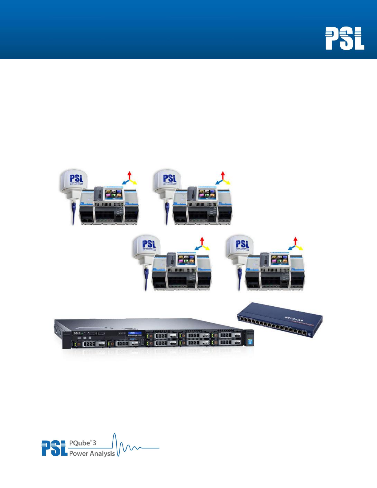
1.3 MicroPMU Quick Start Kit Contents
Linux Server
1x Linux server (hosts the MicroPMU Plotter Application)
1x Power cord for Linux server
MicroPMUs
4x MicroPMU packages: each package includes a MicroPMU and its PM1, MS1, GPS1
and UPS1 modules
4x DIN rails
4x single phase voltage cables
4x current transformers
Networking
5x 10-meter Cat 5e patch cables (Ethernet)
1x 16 port 10/100 Desktop switch
The Quick Start Kit comes preconfigured as follows:
Server: 172.16.1.100
Subnet: 255.255.255.0
uPMU_1: 172.16.1.101
uPMU_2: 172.16.1.102
uPMU_3: 172.16.1.103
uPMU_4: 172.16.1.104
5
Power Sensors Ltd. 980 Atlantic Ave, Alameda CA 94501, USA
Tel ++1-510-522-4400 Fax ++1-510-522-4455 www.PowerSensorsLtd.com
Page 6
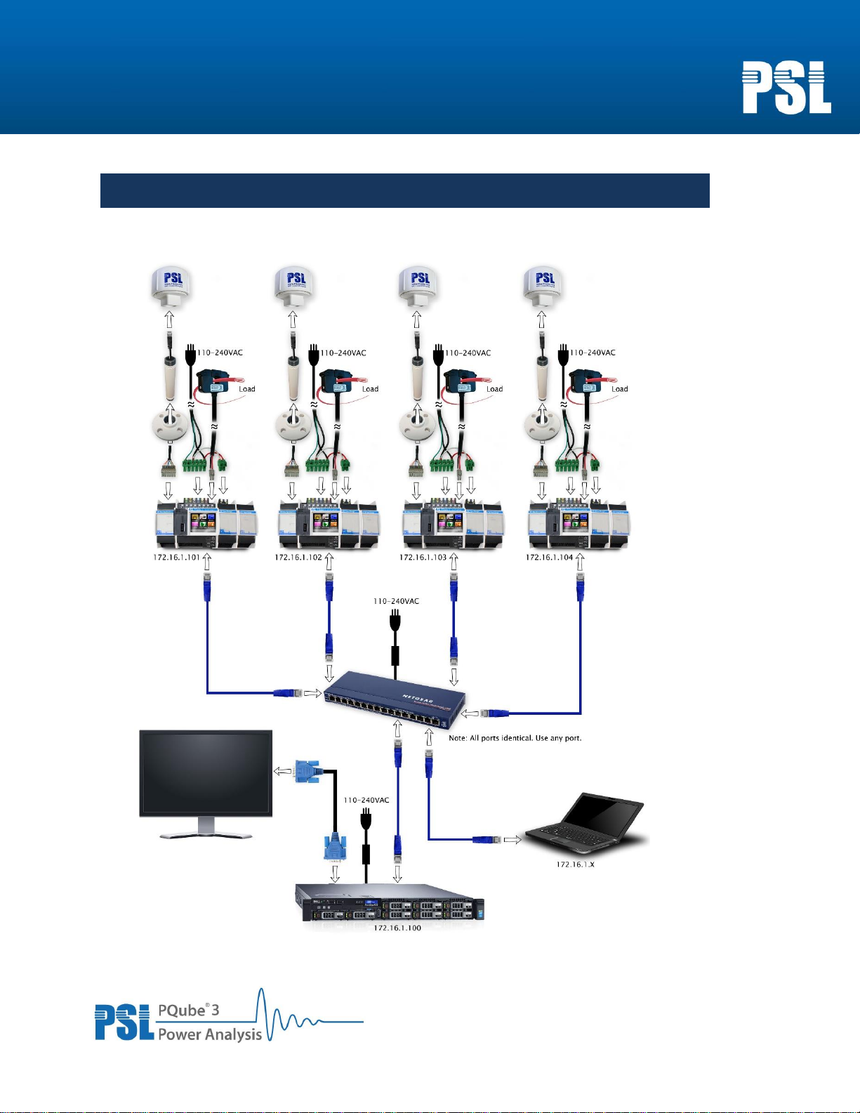
2 Connecting and setting up the MicroPMUs
The following top level diagram illustrates the entire physical setup and connections for the
Quickstart Kit.
6
Power Sensors Ltd. 980 Atlantic Ave, Alameda CA 94501, USA
Tel ++1-510-522-4400 Fax ++1-510-522-4455 www.PowerSensorsLtd.com
Page 7

GPS1 Receiver/Antenna
MS1 Module
1.
The MicroPMU, MS1, PM1 and UPS1 come preassembled on a DIN rail
2.
Mount the GPS hardware
The GPS cable has an 8-pin terminal block on one end and an RJ-45 jack on the other end. The 8-pin
terminal block plugs into the MS1 module, the other end plugs into the GPS1 receiver.
IMPORTANT: Do not plug the RJ-45 end of the GPS cable into a network switch or router.
Place the GPS1 antenna/receiver in an area with direct line of sight to the
sky. For maximum exposure to satellites, mount it on the roof.
If necessary, the GPS cable can be extended using a standard RJ-45 coupler
and a standard CAT5, CAT5E, or CAT6 Ethernet cable (to a maximum length
of 500 feet / 150 meters).
2.1 MicroPMU Setup
7
Power Sensors Ltd. 980 Atlantic Ave, Alameda CA 94501, USA
Tel ++1-510-522-4400 Fax ++1-510-522-4455 www.PowerSensorsLtd.com
Page 8
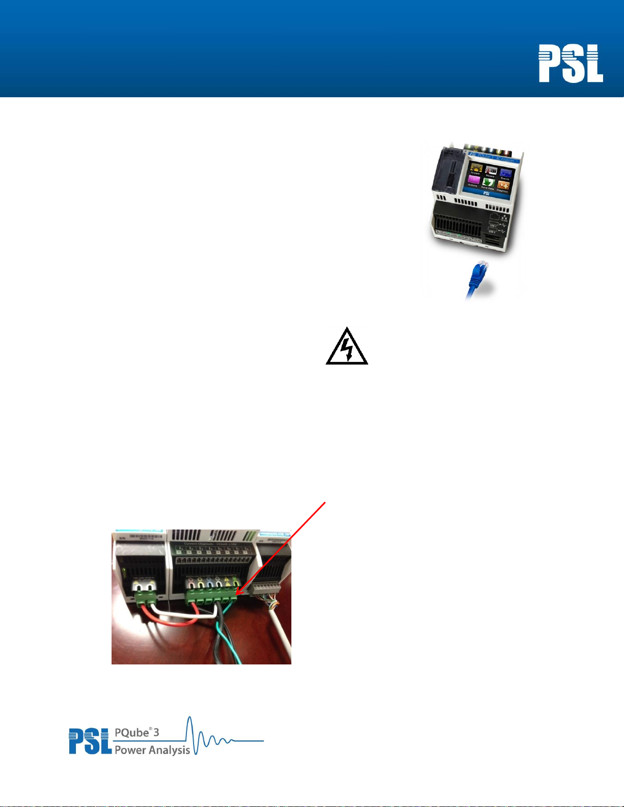
3.
Connect the MicroPMU to the network switch
Plug in one of the provided Ethernet cables between the
MicroPMU and the provided 16-port Ethernet switch. Ethernet
status lights will turn on when connection is established.
4.
Connect wires to mains AC terminals and PM1
Make sure the power is OFF before servicing these terminals.
When installing microPMUs in the field, connect the wires to the high voltage terminal block on the
MicroPMU. They will be labeled L1, L2, L3, N, and Ground.
The power cable comes pre-wired to two terminal blocks in the Quick Start Kit. Plug the larger
terminal block into the PQube 3 mains terminals and plug the smaller one into the power supply
input of the PM1 module.
IMPORTANT: You must ensure that the ground wire is connected to the MicroPMU. This is critical
for accurate phase angle measurements.
8
Power Sensors Ltd. 980 Atlantic Ave, Alameda CA 94501, USA
Tel ++1-510-522-4400 Fax ++1-510-522-4455 www.PowerSensorsLtd.com
Page 9
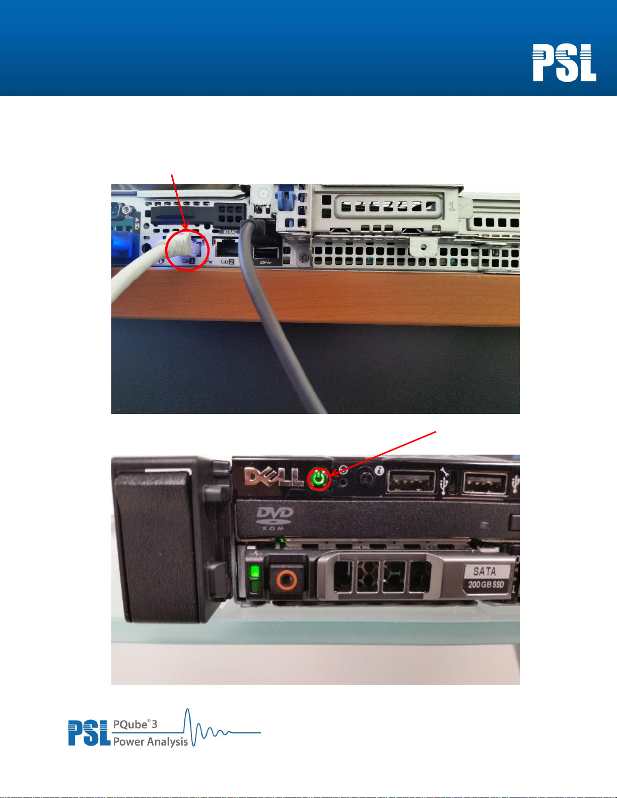
5. Connect the server to network and power
Once all of the MicroPMU units have been set up, use one of the provided Ethernet cables to
connect the Gb1 interface of the server to the provided 16 port Ethernet switch.
Then, connect the server to a suitable power supply and press the power button next to the
“Dell” icon on the top left corner of the front panel.
9
Power Sensors Ltd. 980 Atlantic Ave, Alameda CA 94501, USA
Tel ++1-510-522-4400 Fax ++1-510-522-4455 www.PowerSensorsLtd.com
Page 10

3 Using the MicroPMU Plotter
3.1 Accessing the MicroPMU Plotter
The Quick Start Kit server comes with a pre-installed data plotting web application, known as the
MicroPMU Multiple-Resolution Plotter. The MicroPMU Plotter can be accessed using an internet
browser and by typing the IP address of the Quick Start Kit server: http://172.16.1.100. This IP address
is pre-configured with the Quick Start Kit. If this needs to be changed, refer to the MicroPMU
Administrator Manual. In order to view the plotter from a client computer, the IP configuration of either
the WI-FI or Ethernet adapter must be changed so that the adapter is on the same network as the
Quickstart Server and microPMU units. Refer to the next two sections for instructions on the client
connection from either a Windows or Mac computer.
10
Power Sensors Ltd. 980 Atlantic Ave, Alameda CA 94501, USA
Tel ++1-510-522-4400 Fax ++1-510-522-4455 www.PowerSensorsLtd.com
Page 11

3.1.1 Client Connection via Windows
Go through the following steps to change network adapter settings on Windows.
1) Open the start menu and type “network and sharing center” in the start menu search bar (if
using Windows 10, just type and a search bar will automatically display), and click on the top
result that appears which will open the Network and Sharing Center window.
2) In the left hand pane of the Network and Sharing Center window, click on the link labeled
“Change adapter settings” and another window will appear that displays all of the available
network adapters.
11
Power Sensors Ltd. 980 Atlantic Ave, Alameda CA 94501, USA
Tel ++1-510-522-4400 Fax ++1-510-522-4455 www.PowerSensorsLtd.com
Page 12

3) Find either the Wi-Fi or Ethernet adapter which should be labeled something similar to either
“Wireless Network Connection” or “Local Area Connection” respectively, although these labels
may vary depending on the exact hardware of the client machine. Next, right click on the
adapter and click on “Properties” which will open another small window.
4) In the scroll box, scroll down to the entry labeled “Internet Protocol Version 4” and click on the
text to highlight it, but do not uncheck the box to the left of the text. Now click the “Properties”
button underneath the lower right corner of the scroll box.
12
Power Sensors Ltd. 980 Atlantic Ave, Alameda CA 94501, USA
Tel ++1-510-522-4400 Fax ++1-510-522-4455 www.PowerSensorsLtd.com
Page 13

5) In the new window that appears, there will be two sections of radio button choices. Change the
top radio button selection from “Obtain an IP address automatically” to “Use the following IP
address”. Now set the IP address to an unused IP on the same network as the Quickstart server
and microPMU units. For example, with the default network of “172.16.1.0”, a valid client IP
could be “172.16.1.10”. Next, set the subnet mask to “255.255.255.0” then click the “OK”
button on the bottom right corner of the window and close the other Network and Sharing
Center windows.
13
Power Sensors Ltd. 980 Atlantic Ave, Alameda CA 94501, USA
Tel ++1-510-522-4400 Fax ++1-510-522-4455 www.PowerSensorsLtd.com
Page 14

3.1.2 Client Connection via Mac OS
Go through the following steps to change network adapter settings on Mac OSX.
1) Open the spotlight search (Command (⌘)-Space bar), type “system preferences” and press the
“enter” key.
2) Click on the “Network” icon
14
Power Sensors Ltd. 980 Atlantic Ave, Alameda CA 94501, USA
Tel ++1-510-522-4400 Fax ++1-510-522-4455 www.PowerSensorsLtd.com
Page 15

3) For instructions on adjusting the Wi-Fi adapter, go to step 3a. For instructions on adjusting the
Ethernet adapter, go to step 3b.
a) Select “Wi-Fi” in the left hand pane of the Network window and click the “Advanced”
button toward the bottom right corner.
i) Click the “TCP/IP” tab, set the “Configure IPv4” selection to “Manually” and enter
an unused IP on the same network as the Quickstart Server and microPMU units.
For example, with the default network of “172.16.1.0”, a valid client IP could be
“172.16.1.10”. For the subnet mask, enter “255.255.255.0” then click “OK” toward
the bottom right corner and click “Apply” after the “Advanced” window closes.
15
Power Sensors Ltd. 980 Atlantic Ave, Alameda CA 94501, USA
Tel ++1-510-522-4400 Fax ++1-510-522-4455 www.PowerSensorsLtd.com
Page 16

b) Select “Ethernet” in the left hand pane of the Network window, set the “Configure IPv4”
selection to “Manually” and enter an unused IP on the same network as the Quickstart
Server and microPMU units. For example, with the default network of “172.16.1.0”, a valid
client IP could be “172.16.1.10”. For the subnet mask, enter “255.255.255.0” then click
“Apply” toward the bottom right corner.
16
Power Sensors Ltd. 980 Atlantic Ave, Alameda CA 94501, USA
Tel ++1-510-522-4400 Fax ++1-510-522-4455 www.PowerSensorsLtd.com
Page 17

See 3.3
See 3.4
See 3.5
See 3.4.2
See 3.2
A
B
C D E
See 3.8
See 3.4.1
The different areas of the plotter interface are indicated in the following figure:
3.2 Plotter Header
A. Click help to open a PDF of this document (Quick Start Kit First Steps).
B. Set the language for the plotter interface.
C. Click to hide or show the left-hand panel containing the list of microPMUs and datastreams.
D. Log in to a user account. User accounts can control which users have access to each
microPMU. By default there are no user accounts, so data from all microPMUs is visible.
Refer to the Quick Start Kit Administrator manual for instructions on setting up user
accounts.
E. The “Zoom Out Time” button autoscales the X-axis (time) to fit all recorded data into the
graph. The “Autoscale All” button autoscales the Y-axis (measurement values) to fit all
recorded values within the time scale.
17
Power Sensors Ltd. 980 Atlantic Ave, Alameda CA 94501, USA
Tel ++1-510-522-4400 Fax ++1-510-522-4455 www.PowerSensorsLtd.com
Page 18

3.3 Selecting Streams
A stream is a parameter recorded over time by the MicroPMUs, e.g. phasor amplitude. To view a stream:
1. Click the dropdown arrow to the left of “uPMU” in “Select Streams” section
2. Click the dropdown arrow to the left of “upmu” (database collection name) to show MicroPMUs
3. Expand by clicking the dropdown arrow to the left of a MicroPMU name
4. Select a MicroPMU stream to display (ex. L1MAG or FREQ_L1_1S) by check marking the box to
the left of the stream name
5. Data will appear in the graphing canvas.
The server disk usage is displayed in between the streams tree and time parameter options.
The Quickstart Server comes with a two terabyte solid state drive for database storage. When
the drive reaches about 98% capacity, the server will stop accepting data and a message will
display below the disk usage gauge stating “No longer accepting new data. Drive is full”. A new
drive will need to be used or the existing data will need to be backed up and a fresh database
instance will need to be created on the existing drive. This procedure will need to be done by
the Quickstart Server administrator or instructions on these procedures may be found in the
Administrator manual.
18
Power Sensors Ltd. 980 Atlantic Ave, Alameda CA 94501, USA
Tel ++1-510-522-4400 Fax ++1-510-522-4455 www.PowerSensorsLtd.com
Page 19

3.4 Setting the min and max range of the X-axis and Y-axis
3.4.1 To set the X-axis
Use the scroll wheel on the mouse to zoom in and out of the X-axis.
Click and drag the mouse to pan left or right along the X-axis.
Each microPMU records data at a rate of 120 times per second. When zoomed in close enough,
each individual measurement point can be seen.
When zooming out, the plotter software will automatically average the data points before
displaying them.
When zooming out even farther, the data will appear as a line inside of a shaded area. The line
represents the average value. The upper/lower boundaries of the shaded area represent the
maximum and minimum values, respectively.
19
Power Sensors Ltd. 980 Atlantic Ave, Alameda CA 94501, USA
Tel ++1-510-522-4400 Fax ++1-510-522-4455 www.PowerSensorsLtd.com
Page 20

The minimum and maximum X-axis value may also be manually set. Click the Time tab
underneath the graph and set the Start Date and End Date fields.
Shortcut buttons are available for Start Date (past 1 year) and End Date (now).
Set the time zone using the dropdown menu on the right, and check the DST box to set Daylight
Savings Time if necessary.
Click the “Manual Zoom” button to refresh the plotter graph.
20
Power Sensors Ltd. 980 Atlantic Ave, Alameda CA 94501, USA
Tel ++1-510-522-4400 Fax ++1-510-522-4455 www.PowerSensorsLtd.com
Page 21

3.4.2 To set the Y-axis
Under the Axes tab, clicking “Autoscale” fits the Y-axis to the data presently in the graph.
If necessary, the minimum and maximum Y-axis values may also be entered manually.
21
Power Sensors Ltd. 980 Atlantic Ave, Alameda CA 94501, USA
Tel ++1-510-522-4400 Fax ++1-510-522-4455 www.PowerSensorsLtd.com
Page 22

3.5 Setting line color and labels for each data stream
In the “Legend” tab underneath the graph, the color and label for each data stream in the graph
may be changed.
To set the color, click the box under the Color column to reveal a color palette.
To set the label, click the dropdown menu under the Axis Name column.
Click the Stream name to highlight the individual channel on the graph. This can be useful when
viewing many streams on the same graph.
In addition, clicking the name of the stream also displays a number on the graph that describes the
density of data points per pixel and any gaps in data recording are indicated on the graph.
22
Power Sensors Ltd. 980 Atlantic Ave, Alameda CA 94501, USA
Tel ++1-510-522-4400 Fax ++1-510-522-4455 www.PowerSensorsLtd.com
Page 23

3.6 Custom Axis Labels
Axis labels for each parameter can be set to a custom value. For example, if comparing power
input vs power output, it can be helpful to set the units to Watts (in) and Watts (out), respectively.
To create custom units:
1. Under the Axes tab, click Add a Y-axis. A new entry will be added to the bottom of the list.
2. Enter a new axis label in the Axis Name field
3. Under the Legend tab, choose a stream and click the dropdown menu under the Axis Name
column and select the newly created Axis Name.
To remove a custom axis, go to the Axes tab and click the red X button next to the custom axis in the
list.
23
Power Sensors Ltd. 980 Atlantic Ave, Alameda CA 94501, USA
Tel ++1-510-522-4400 Fax ++1-510-522-4455 www.PowerSensorsLtd.com
Page 24

3.7 Y-axis Positions
For each stream, the Y-axis can be moved to the left or right of the graph. This is useful for two
graphs with different units (volts and degrees, for example). Under the Axes tab, use the left or
right buttons to move the Y-axis. Clicking on the “X” hides the axis.
24
Power Sensors Ltd. 980 Atlantic Ave, Alameda CA 94501, USA
Tel ++1-510-522-4400 Fax ++1-510-522-4455 www.PowerSensorsLtd.com
Page 25

3.8 Export Tools
Generate Permalink
Graphs can be shared with others using the “Generate Permalink” button. It creates a URL
shortcut that opens the MicroPMU Plotting Application and displays the measurements with the
associated time, axes, and parameters selected at the time of permalink generation.
The link can be copied, saved, or emailed. Clicking the link will display the exact same graph.
Export to SVG Image
Click “Export Graph to SVG Image” to generate a picture of the graph. Click “Download Image” to
save it to the client computer.
Export Graph to CSV Files
The “Export Graph to CSV File” button is used to create a CSV (comma separated values) file of the
plotter graph’s data for the values seen within the current graphing canvas.
First, select the correct power frequency for the data in the graph. This frequency sets the data
interval in the CSV, so it is important to choose the correct frequency or the resulting CSV file will
have inaccurate sample data. MicroPMUs on 50Hz systems will record 100 measurements per
second. MicroPMUs on 60Hz systems record 120 measurements per second.
After clicking “Export Graph to CSV File”, a prompt to set the CSV file time interval will appear . The
available time intervals to choose from are 1 day, 1 hour, 30 minutes, 5 minutes, 1 minute, 1
second, 1 cycle and ½ cycle. The CSV file contains minimum, average, and maximum values for
each parameter.
Click “Create CSV File” to create a csv file which will be saved to the downloads folder by default.
25
Power Sensors Ltd. 980 Atlantic Ave, Alameda CA 94501, USA
Tel ++1-510-522-4400 Fax ++1-510-522-4455 www.PowerSensorsLtd.com
Page 26

Below is a sample CSV export file.
The first column displays a Unix time stamp (number of nanoseconds elapsed since January 1, 1970
00:00:00 UTC) for the beginning of the time interval.
The second column displays local time (according to plotter settings) when the CSV file was
generated.
Columns following after will display data for each stream in the graph. Each stream will have four
columns to display “cnt”, “min”, “mean” and “max”.
The “cnt” column displays the number of ½ cycles in the chosen time interval (row).
The “min”, “mean”, and “max” columns display, respectively, the minimum, average, and
maximum values recorded in the chosen time interval.
26
Power Sensors Ltd. 980 Atlantic Ave, Alameda CA 94501, USA
Tel ++1-510-522-4400 Fax ++1-510-522-4455 www.PowerSensorsLtd.com
Page 27

4 Troubleshooting
Symptom:
A “No longer accepting new data” message is displayed underneath the data usage gauge on the
plotter website.
Solution #1:
The Quickstart Server comes with a two terabyte solid state drive for database storage. When the
drive reaches about 98% capacity, the server will stop accepting data and a message will display
below the disk usage gauge stating “No longer accepting new data. Drive is full”. A new drive will
need to be used or the existing data will need to be backed up and a fresh database instance will
need to be created on the existing drive. This procedure will need to be done by the Quickstart
Server administrator or instructions on these procedures may be found in the Administrator
manual.
For technical assistance or the latest version of this document, please call 1-510-522-4400 or email:
support@powersensorsltd.com with any further questions.
27
Power Sensors Ltd. 980 Atlantic Ave, Alameda CA 94501, USA
Tel ++1-510-522-4400 Fax ++1-510-522-4455 www.PowerSensorsLtd.com
 Loading...