

Page 1
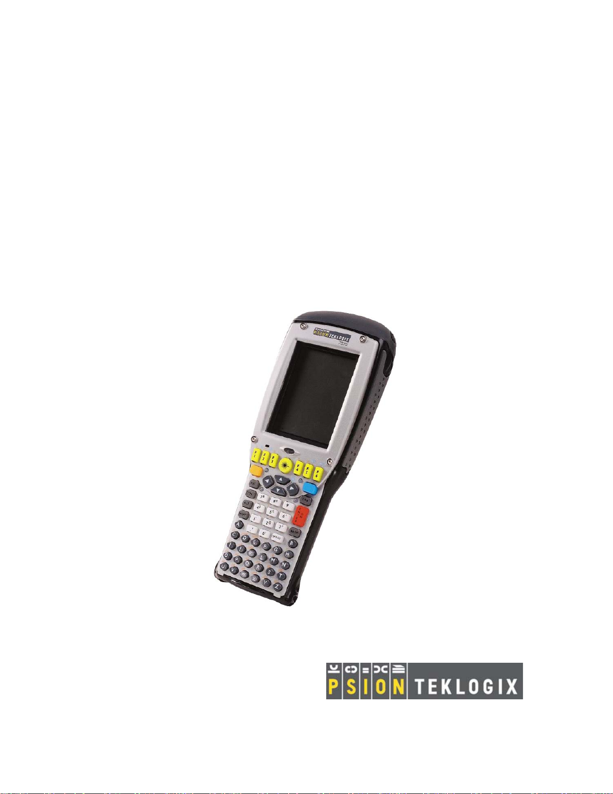
7535 Hand-Held
Computer
User Manual
May 16, 2003 Part No. 8000007.A
ISO 9001 Certified
Quality Management System
Page 2

Page 3

© Copyright 2003 by Psion Teklogix Inc., Mississauga, Ontario
This document and the information it contains is the property of Psion Teklogix Inc.,
is issued in strict confidence, and is not to be reproduced or copied, in whole or in
part, except for the sole purpose of promoting the sale of Teklogix manufactured
goods and services. Furthermore, this document is not to be used as a basis for
design, manufacture, or sub-contract, or in any manner detrimental to the interests
of Psion Teklogix Inc.
All trademarks are the property of their respective holders.
Page 4

Return-To-Factory Warranty
Psion Teklogix warrants a return-to-factory warranty for a period of one year from
shipment. The warranty on Psion Teklogix manufactured equipment does not extend
to any product that has been tampered with, altered, or repaired by any person other
than an employee of an authorized Psion Teklogix service organization. See Psion
Teklogix terms and conditions of sale for full details.
Service
When requesting service, please provide information concerning the nature of the
failure and the manner in which the equipment was used when the failure occurred.
Type, model, and serial number should also be provided. Before returning any
products to the factory, call the Customer Services Group for a Return
Authorization number .
Support Services
Psion Teklogix provides a complete range of product support services to its customers. In North America, these services can be accessed through the Psion Teklogix
Helpdesk. The Helpdesk coordinates repairs and training, helps you to troubleshoot
problems over the phone and arranges for technicians or engineers to come to your
site. For contact information and a listing of worldwide offices, please refer to
Appendix A: Support Services And Worldwide Offices.
Disclaimer
Every effort has been made to make this material complete, accurate and up-to-date.
Teklogix Inc. reserves the right to make changes without notice and shall not be
held responsible for damages resulting from reliance on the material presented in
this manual.
Page 5

P
ROGRAM
L
ICENSE
A
GREEMENT
Microsoft's End User License Agreement
You have acquired an item (“DEVICE”) that includes software licensed from
Microsoft Licensing Inc. or its affiliates (“MS”). Those installed software products
of MS origin, as well as associated media, printed materials, and “online” or electronic documentation (“SOFTWARE”) are protected by copyright laws and international copyright treaties, as well as other intellectual property laws and treaties. The
SOFTWARE is licensed, not sold.
IF YOU DO NOT AGREE TO THIS END USER LICENSE AGREEMENT
(“EULA”), DO NOT USE THE DEVICE OR COPY THE SOFTWARE.
INSTEAD, CONTACT PSION TEKLOGIX INC IMMEDIATELY FOR
INSTRUCTIONS ON RETURN OF THE UNUSED DEVICE(S) FOR A
REFUND. ANY USE OF THE SOFTWARE, INCLUDING BUT NOT LIMITED
TO USE ON THE DEVICE, WILL CONSTITUTE YOUR AGREEMENT TO
THIS EULA (OR RATIFICATION OF ANY PREVIOUS CONSENT).
GRANT OF LICENSE. The SOFTWARE is licensed, not sold. This EULA grants
you the following rights to the SOFTWARE:
• You may use the SOFTWARE only on the DEVICE.
• NOT FAULT T OLERANT. THE SOFTWARE IS NOT FAULT T OLERANT. PSION TEKLOGIX INC. HAS INDEPENDENTLY DETERMINED HOW TO USE THE SOFTWARE IN THE DEVICE, AND MS
HAS RELIED UPON PSION TEKLOIGX INC. T O CONDUCT SUFFICIENT TESTING TO DETERMINE THAT THE SOFTWARE IS SUITABLE FOR SUCH USE.
Teklogix 7535 Hand-Held Computer User Manual I
Page 6

License Agreement
• NO WARRANTIES FOR THE SOFTWARE. THE SOFTWARE is
provided “AS IS” and with all faults. THE ENTIRE RISK AS TO
SATISFA CTORY Q UALITY, PERFORMANCE, ACCURACY, AND
EFFORT (INCLUDING LACK OF NEGLIGENCE) IS WITH YOU.
ALSO, THERE IS NO WARRANTY A GAINST INTERFERENCE WITH
YOUR ENJOYMENT OF THE SOFTWARE OR AGAINST
INFRINGEMENT. IF YOU HAVE RECEIVED ANY WARRANTIES
REGARDING THE DEVICE OR THE SOFTWARE, THOSE WARRANTIES DO NOT ORIGINATE FR OM, AND ARE NOT BINDING ON, MS.
• Note on Java Support. The SOFTWARE may contain support for programs
written in Java. Java technology is not fault tolerant and is not designed,
manufactured, or intended for use or resale as online control equipment in
hazardous environments requiring fail-safe performance, such as in the
operation of nuclear facilities, aircraft navigation or communication systems, air traffic control, direct life support machines, or weapons systems,
in which the failure of Jav a technology could lead directly to death, personal injury, or severe physical or environmental damage. Sun Microsystems, Inc. has contractually obligated MS to make this disclaimer.
• No Liability for Certain Damages. EXCEPT AS PROHIBITED BY LAW,
MS SHALL HAVE NO LIABILITY FOR ANY INDIRECT, SPECIAL,
CONSEQUENTIAL OR INCIDENTAL D AMAGES ARISING FROM
OR IN CONNECTION WITH THE USE OR PERFORMANCE OF THE
SOFTWARE. THIS LIMITATION SHALL APPLY EVEN IF ANY
REMED Y FAILS OF ITS ESSENTIAL PURPOSE. IN NO EVENT
SHALL MS BE LIABLE FOR ANY AMOUNT IN EXCESS OF U.S.
TWO HUNDRED FIFTY DOLLARS (U.S.$250.00).
• Limitations on Reverse Engineering, Decompilation, and Disassembly. You
may not reverse engineer, decompile, or disassemble the SOFTWARE,
except and only to the extent that such acti vity is expressly permitted by
applicable law notwithstanding this limitation.
• SOFTWARE TRANSFER ALLO WED BUT WITH RESTRICTIONS. Y ou
may permanently transfer rights under this EULA only as part of a permanent sale or transfer of the Device, and only if the recipient agrees to this
EULA. If the SOFTWARE is an upgrade, any transfer must also include all
prior versions of the SOFTWARE.
II
Teklogix 7535 Hand-Held Computer User Manual
Page 7

License Agreement
• EXPOR T RESTRICTIONS. If these licensing terms are not labeled “North
America Only Version” and the SOFTWARE is not identified as “North
America Only Version” on the SOFTWARE packaging or other written
materials, then the following terms apply: Export of the Department,
Bureau of Export Administration (BXA). You agree to comply with the
EAR in the export or re-export of the SOFTWARE: (i) to any country to
which the U.S. has embargoed or restricted the export of goods or services,
which as of May 1999 include, but are not necessarily limited to Cuba, Iran,
Iraq, Libya, North Korea, Sudan, Syria, and the Federal Republic or Yugoslavia (including Serbia, but not Montene gro), or to any national of any
such country, wherever located, who intends to transmit or transport the
SOFTWARE back to such country; (ii) to any person or entity who you
know or have reason to know will utilize the SOFTWARE or portion
thereof in the design, development or production of nuclear, chemical, or
biological weapons; or (iii) to any person or entity who has been prohibited
from participating in U.S. export transactions by any federal agency or the
U.S. government. You warrant and represent that neither the BXA nor any
other U.S. federal agency has suspended, revoked or denied your export
privileges. F or additional information see
http://www.microsoft.com/exporting/.
Teklogix 7535 Hand-Held Computer User Manual III
Page 8

Page 9

ABLE OF
T
C
ONTENTS
Program License Agreement
Approvals And Safety Summary
..............................I
...........................xi
Chapter 1: Introduction
1.1 About This Manual ............................3
1.2 Text Conventions.............................4
1.3 About The 7535 Hand-Held Computer ..................5
1.3.1 Features...............................5
1.3.2 The 7535 Hand-Held Computer ..................7
1.3.3 The 7535 Hand-Held Safety Labels ................9
Chapter 2: Unpacking & Basic Checkout
2.1 Preparing The 7535 For Operation ....................13
2.1.1 Equipment You Need To Get Started ...............13
2.1.2 Charging The Battery .......................13
2.1.3 Attaching Carrying Accessories ..................13
2.1.3.1 Attaching The Hand Strap................14
2.1.3.2 Attaching The Pistol Grip ................15
2.2 Powering Up The 7535 And Configuring The Radio ...........16
2.2.1 Installing The Battery And Switching The 7535 On........17
2.2.2 Configuring An IEEE 802.11 Radio ................18
2.3 Advanced NETWLAN Settings......................22
2.3.1 Preferred Networks.........................23
2.3.2 Advanced Network Access.....................23
2.3.3 Configuring WEP Keys ......................24
2.4 Additional Radio Security Options....................28
2.5 Checking The Scanner ..........................29
2.6 Uploading New Applications.......................29
2.7 Calibrating The Touchscreen.......................30
Teklogix 7535 Hand-Held Computer User Manual i
Page 10

Contents
Chapter 3: Getting To Know Your 7535
2.8 Resetting The 7535 Hand-Held .....................30
3.1 Features Of The 7535 ..........................33
3.2 The Battery................................34
3.2.1 Battery Safety ...........................34
3.2.2 Removing And Installing The Battery Pack ...........34
3.2.3 Charging The Battery .......................35
3.3 Switching The 7535 Hand-Held On And Off ..............36
3.4 The Keyboard ..............................37
3.4.1 Modifier Keys...........................38
3.4.1.1 Activating Modifier Keys................39
3.4.1.2 Locking Modifier Keys.................39
3.4.2 The Keys .............................39
3.4.3 The 58-Key Keyboard ......................40
3.4.4 The 36-Key Keyboard ......................40
3.4.5 The Keypad Backlight ......................42
3.5 The Display...............................43
3.5.1 Adjusting The Display Backlight.................43
3.5.2 Adjusting The Contrast On Monochrome Displays .......43
3.5.3 Calibrating The Touchscreen ...................44
3.6 7535 Hand-Held Computer Indicators..................45
3.6.1 LEDs ...............................45
3.6.1.1 Charge LEDs ......................46
3.6.1.2 Radio T raffic LEDs...................46
3.6.1.3 Scan LEDs .......................47
3.6.2 Onscreen Indicators........................47
3.6.3 Audio Indicators .........................49
3.6.3.1 Adjusting The Beeper Volume .............49
3.7 Internal Scanners.............................50
3.7.1 Warnings .............................51
3.7.2 Scanning Techniques .......................51
3.7.3 Scan LED Indicators .......................52
3.7.4 Troubleshooting..........................52
3.7.5 Operating One Dimensional (1D) Internal Laser Scanners....53
3.7.6 Operating Internal PDF Laser Scanners .............53
3.7.7 Operating Internal Two Dimensional (2D) Imager Scanners . . 53
ii
Teklogix 7535 Hand-Held Computer User Manual
Page 11

Contents
3.8 Connecting & Disconnecting Tethered Peripherals............54
3.9 Monitoring The Battery And Maximizing Run Time...........55
3.10 Monitoring The Network Connection...................57
3.11 Uploading Data In A Docking Station ..................57
3.12 General Maintenance ...........................58
3.12.1Caring For The Touchscreen....................58
3.12.2Cleaning The 7535 .........................58
Chapter 4: Working With Windows CE
4.1 Navigating In Windows CE And Applications..............61
4.1.1 Navigating Using A Touchscreen And Stylus ...........61
4.1.2 Navigating Using The Keyboard..................61
4.2 Working With Files, Folders And Programs ...............62
4.3 The Startup Desktop............................63
4.3.1 Accessing Desktop Icons......................63
4.3.2 The Taskbar ............................64
4.3.2.1 Using The Taskbar....................64
4.4 The System Menu.............................65
4.5 Using A Dialogue Box ..........................68
Chapter 5: Configuration
5.1 The Control Panel .............................73
5.2 Control Panel Icons ............................74
5.3 Basic Setup................................76
5.3.1 Display Properties .........................76
5.3.1.1 Display Contrast .....................77
5.3.1.2 Display Backlight ....................77
5.3.1.3 Display Appearance ...................79
5.3.2 Keyboard Properties ........................80
5.3.2.1 Ke y Repeat........................80
5.3.2.2 Ke yboard Backlight ...................81
5.3.2.3 Ke yboard One Shot Modes ...............82
5.3.3 Power Management Properties...................83
5.3.3.1 Battery Capacity .....................83
5.3.3.2 Power Saving Schemes .................84
5.3.4 Calibrating The Touchscreen ...................85
5.4 Advanced Configuration .........................86
Teklogix 7535 Hand-Held Computer User Manual iii
Page 12

Contents
5.5 Scanner Properties ............................86
5.5.1 Scanner Options..........................87
5.5.2 Bar Codes .............................89
5.5.3 Bar Code Settings.........................90
5.5.3.1 Code 39 Settings ....................90
5.5.3.2 Code 128 Settings ...................93
5.5.3.3 EAN 13 Settings ....................94
5.5.3.4 EAN 8 .........................96
5.5.3.5 UPC And EAN Settings ................97
5.5.3.6 UPC A Settings.....................97
5.5.3.7 UPC E Settings.....................98
5.5.3.8 Codabar Size And Characters .............99
5.5.3.9 Code 93 Size And Characters .............99
5.5.3.10 Code 11.........................100
5.5.3.11 I 2 of 5 Settings.....................101
5.5.3.12 MSI/PLESSY Settings .................102
5.5.3.13 D 2 of 5 Settings ....................103
5.5.3.14 IATA 2 of 5 Settings ..................104
5.5.3.15 Postal: Australian....................104
5.5.3.16 Postal: Japanese ....................105
5.5.3.17 Postal: Korean .....................105
5.5.3.18 Postal: PlaNET .....................105
5.5.3.19 Postal: PostNET ....................105
5.5.3.20 Postal: Royal Mail ...................105
5.5.3.21 DataMatrix (2D) ....................106
5.5.3.22 Maxicode (2D) .....................106
5.5.3.23 PDF-417 (2D) .....................106
5.5.3.24 Micro PDF-417 (2D) ..................107
5.5.3.25 QR Code (2D) .....................107
5.5.3.26 RSS Code (2D).....................107
5.5.3.27 Aztec ..........................107
iv
Chapter 6: Tekterm Application
6.1 The Tekterm Application.........................113
6.2 Additional Keyboard Functions .....................113
6.2.1 Function Keys And Softkey Function Keys ...........113
6.2.1.1 Function Ke ys .....................113
6.2.1.2 Softkey Function Keys .................114
6.2.2 Macro Keys ............................115
6.3 Keyboard Modes.............................116
Teklogix 7535 Hand-Held Computer User Manual
Page 13

Contents
6.3.1 View Mode ............................116
6.3.1.1 Changing Font Sizes..................116
6.3.1.2 Panning The Screen Contents .............116
6.3.1.3 Exiting V iew Mode ..................117
6.3.2 Menu Mode And Switching Between Applications .......118
6.3.2.1 Using The T ask Manager To Switch Between Applications
118
6.4 The Tekterm Status Area........................119
6.5 TESS Emulation.............................120
6.5.1 Configuration...........................120
6.5.2 Working With Multiple Sessions ................120
6.5.3 The Field Types .........................120
6.5.4 IBM 5250 Emulation Keys....................121
6.5.5 Data Entry ............................121
6.5.5.1 TESS Edit Modes And Cursor Movement ......122
6.5.5.2 <DEL> Ke y Behaviour In TESS ...........123
6.5.5.3 <BKSP> Ke y Behaviour In TESS...........124
6.5.6 TESS Status Message ......................125
6.5.7 Lock Messages ..........................126
6.5.8 Control Commands........................126
6.5.9 Resetting A TESS Session ....................126
6.5.10The Local Menu .........................127
6.5.11Selecting Another Host Computer ................127
6.5.12Queuing Mode ..........................128
6.6 ANSI Emulation.............................128
6.6.1 Configuration...........................128
6.6.2 Sending Data To The Host ....................129
6.6.3 Psion Teklogix Keyboard And VT220 Equivalent Keys ....129
6.6.4 Block Mode (Local Editing) ...................130
6.6.5 Working With Sessions .....................131
6.6.5.1 Establishing A New Session..............131
6.6.5.2 Listing Sessions And Moving To Other Sessions . . . 131
6.6.5.3 Closing A Session ...................131
6.6.5.4 Printing A Screen ...................132
6.6.5.5 Smart Echo – Disabling ................132
6.7 The Tekterm Startup Display Menu...................132
6.8 W orking W ith Menus ..........................133
6.8.1 Using The Keyboard To Navigate Through Menus .......133
Teklogix 7535 Hand-Held Computer User Manual v
Page 14

Contents
6.8.1.1 Sub-Menus .......................133
6.8.1.2 Numeric Parameters ..................134
6.8.1.3 Y/N Parameters.....................134
6.8.1.4 Alpha Parameters....................134
6.8.1.5 String Entry Parameters ................135
6.8.2 Using The Touchscreen To Navigate Through Menus......137
6.8.2.1 Sub-Menus .......................137
6.8.2.2 Numeric Parameters ..................137
6.8.2.3 Y/N Parameters.....................138
6.8.2.4 Alpha Parameters....................138
6.8.2.5 String Entry Parameters ................138
6.8.3 Saving Changes To Parameters..................138
6.8.4 Retrieving Default Parameter Values...............139
6.9 Resetting The 7535 Hand-Held Computer ...............139
6.10 The Parameters Menu ..........................139
6.10.1Security Settings .........................140
6.11 Display Options .............................140
6.12 More Parameters .............................141
6.13 Radio Parameters ............................142
6.14 System Parameters............................145
6.14.1Keyboard .............................145
6.14.1.1 Macros .........................145
6.14.1.2 Indicators ........................148
6.14.1.3 Softkeys.........................149
6.14.1.4 Cntrl Panel .......................149
6.14.2Audio ...............................150
6.14.3Power Mgmt ...........................151
6.14.4Security ..............................151
6.14.4.1 Default Mode......................151
6.14.4.2 User Level Options...................152
6.14.4.3 Sup. Password .....................152
6.15 Scanner Control Panel ..........................153
6.16 View Manager ..............................154
6.16.1Split Screen ............................155
6.16.1.1 Splitting And Displaying Screens ...........155
6.16.1.2 Moving Between Split Screens.............156
6.16.1.3 Toggling Between Full & Split Screens ........156
6.16.1.4 Using The Asterisk As A W ild Card ..........157
6.16.2Custom Characters (Unicode™) .................157
vi
Teklogix 7535 Hand-Held Computer User Manual
Page 15

Contents
6.16.2.1 Creating A Unicode™ Character ...........157
6.16.2.2 Displaying The Unicode™ Pop-up Window .....158
6.17 Applications ...............................160
6.17.1ANSI Settings ..........................161
6.17.1.1 Host Conn .......................162
6.17.1.2 Screen .........................163
6.17.1.3 Xmit Modes ......................166
6.17.1.4 Kbd Modes.......................170
6.17.1.5 Edit Modes.......................173
6.17.1.6 Serial..........................174
6.17.1.7 Host Char Set .....................174
6.17.1.8 Anchor V iew......................175
6.17.2TESS Settings ..........................176
6.17.2.1 Host Conn........................177
6.17.2.2 Screen .........................178
6.17.2.3 Characters .......................180
6.17.2.4 Tests ..........................182
6.17.2.5 Features ........................183
6.17.2.6 Scanner.........................186
6.17.2.7 Fields..........................188
6.17.2.8 Anchor V iew......................190
6.18 Ports– T ether And Console .......................191
6.18.1Tether And Console Port Peripheral Options ..........191
6.18.2Tether And Console Port Parameter Settings ..........192
6.18.3Tether And Console Port Scan-See Parameters .........195
6.18.3.1 Scan-See Sub-Menu – Mapping The Viewport ....195
6.18.3.2 Scan-See Keyboard Mapping .............200
6.19 Network .................................201
6.19.1Network Ctrl Panel Settings ...................201
6.19.1.1 NETWLAN – Configuring The Radio ........202
6.19.2802.IQ v2.............................202
Chapter 7: Peripheral Devices & Accessories
7.1 External Bar Code Readers .......................207
7.1.1 PowerScan™ Standard, LR and XLR Bar Code Scanners . . . 207
7.1.2 Entering Data With The Bar Code Reader............207
7.2 The 7535 Battery ............................207
7.2.1 Lithium-Ion Battery Safety Precautions .............208
7.3 Important Charger Safety Instructions .................209
Teklogix 7535 Hand-Held Computer User Manual vii
Page 16

Contents
7.4 Chargers.................................210
7.5 Gang Charger..............................210
7.5.1 Installation ............................210
7.5.2 Operator Controls .........................211
7.5.3 Charge Indicators .........................211
7.5.4 Charging Batteries ........................212
7.5.5 Troubleshooting..........................212
7.5.5.1 Excessiv e Charge Duration...............212
7.5.5.2 Indicator Flashing Red .................212
7.5.5.3 Power LED Does Not Light Up ............213
7.5.5.4 Indicator Does Not Light When Battery Installed . . .213
7.6 Combo Charger.............................213
7.6.1 Installation ............................213
7.6.2 Operator Controls .........................214
7.6.3 Using the Combo Charger With The 7535 ............214
7.6.4 7.2.4 Charging The Spare Battery ................214
7.6.5 Charge Indicators .........................215
7.6.6 Troubleshooting..........................215
7.7 Combo Dock...............................216
7.7.1 Installation ............................216
7.7.2 Using The Combo Dock .....................216
7.7.3 Network Access..........................216
7.7.4 Troubleshooting..........................217
7.8 Quad Dock................................217
7.8.1 Installation ............................217
7.8.2 Indicators And Controls .....................218
7.8.3 Using The Quad Dock ......................218
7.8.4 Network Access..........................218
7.8.4.1 Network Addressing ..................218
7.8.5 Battery Charging .........................219
7.8.6 Troubleshooting..........................219
7.8.6.1 Network Link Unsuccessful ..............219
7.8.6.2 7535 LED Does Not Light When Dock ed .......219
7.8.6.3 7535 Battery Does Not Charge When Docked.....219
7.9 Portable Docking Module (PDM) ....................219
7.10 Bluetooth Peripherals ..........................222
7.11 The 7535 Picker Cradle .........................222
viii
Teklogix 7535 Hand-Held Computer User Manual
Page 17

Contents
7.11.1Mounting Recommendations ..................223
7.11.1.1 Mounting T emplate ..................223
7.11.2Wiring Guidelines ........................224
7.11.3Using The Picker Cradle .....................224
7.11.4Maintaining The Picker Cradle .................224
7.11.5The Powered Cradle Option ...................225
7.11.5.1 Wiring Vehicle Power T o The Cradle .........225
7.11.6The Port Replicator........................226
Chapter 8: Specifications
8.1 7535 Hand-Held Computer Specifications...............229
8.2 Radio Specifications...........................230
8.3 Bar Code Scanning ...........................230
8.3.1 Internal Scanners .........................231
8.3.2 Internal Scanner Port .......................231
8.3.3 External Scanners ........................231
8.4 Internal Scanner Specifications.....................231
8.4.1 SE1200 High Performance & Long Range Specs ........232
8.4.2 SE1223 Advanced Long Range & SE2223 2-D Specs .....233
8.4.3 Symagery SX4000 & Welch Allyn IT4200 Imager Specs . . . 234
8.5 External Scanner Specifications.....................236
8.5.1 PowerScan™ LR and XLR Industrial Scanner Specs ......236
8.5.2 PowerScan™ Standard Range Scanner Specs ..........238
8.6 Lithium-Ion Battery Pack ........................240
Appendix A: Support Services And Worldwide Offices
A.1 Support Services.............................A-1
A.1.1 Canada and USA: Technical Support and Repair Services . . . A-1
A.1.2 International Support ......................A-1
Appendix B: Port Pinouts And Cable Diagrams
B.1 7535 Tether Port Pinout .........................B-1
B.2 Docking Port & Battery Connector - TBD ...............B-1
Teklogix 7535 Hand-Held Computer User Manual ix
Page 18

Page 19

A
PPROVALS
A
ND
S
AFETY
S
Declaration Of Conformity
Product: 7535 Hand Held Micro-computer
Application of Council EMC Directive: 89/336/EEC
Directive(s): Low Voltage Directive: 73/23/EEC
Conformity Declared EN 301 489-17: v1.1.1; 09-2000
to Standards: EN 50082-1:1997; EN 50082-2:1995;
EN 55022:1994, Class B;
EN 61000-3-2; EN 61000-3-3
EN 55024:1998;
EN 61000-4-2; ±4kV CD; ±8kV AD
EN 61000-4-3; 3V/m, 80-1000 MHz
EN 61000-4-4; ±0.5kV on I/O lines, ±1kV Power lines
EN 61000-4-5; ±2kV Common; ±1kV Differential mode
EN 61000-4-6; 3VRMS, 150kHz-80MHz
EN 61000-4-11; AC Mains Ports
EN 60950: 1992 + A1 + A2 + A3 + A4 +A11
Manufacturer: PSION TEKLOGIX INC.
2100 Meadowvale Boulevard
Mississauga, Ontario, Canada
L5N 7J9
Year of Manufacture: 2003
Manufacturer’ s Address PSION TEKLOGIX S.A.
in the European La Duranne; 135 Rue Rene Descartes; BP 421000
Community: 13591 Aix-En-Provence
Cedex 3; France
Type of Equipment: Information Technology Equipment
Equipment Class: Commercial and Light Industrial
UMMARY
I the undersigned hereby declare that the equipment specified above conforms to
the above directives and standards.
Manufacturer: Rob Williams
Vice President of Engineering
Psion Teklogix Inc. Ontario
Legal Representative Domique Binckly
Vice President International Sales
Psion Teklogix S.A. France
Teklogix 7535 Hand-Held Computer User Manual xi
Page 20

Approvals And Safety Summary
This equipment complies with Class B Part 15 of the FCC rules.
Operation is subject to the following two conditions:
1. This device may not cause harmful interference, and
2. This device must accept any interference received, including interference that may cause undesired operation.
Changes or modifications not expressly approved by Psion Teklogix, the party
responsible for compliance, may void the user's authority to operate the equipment.
DO N
OT OPERATE IN AN EXPLOSIVE ATMOSPHERE
Operating Psion Teklogix equipment where explosive gas is present may
result in an explosion.
DO NOT REMOVE COVERS OR OPEN ENCLOSURES
To avoid injury, the equipment covers and enclosures should only be
removed by qualified service personnel. Do not operate the equipment
without the covers and enclosures properly installed.
CAUTION!
Danger of explosion if a 7535 battery is incorrectly handled, charged,
disposed of or replaced. Replace only with the same or equivalent type
recommended by the manufacturer. Dispose of used batteries according to
the instructions described in “Lithium-Ion Battery Safety Precautions” on
page 208. Carefully revie w all battery safety issues.
VORSICHT!
Explosiongefahr bei unsachgemäßem Austausch der Batterie Ersatz nur
durch denselben oder einen vom Hersteller empfohlenen gleichwertigen
Typ. Entsorgung gebrauchter Batterien nach Angaben des Herstellers.
xii
Teklogix 7535 Hand-Held Computer User Manual
Page 21

INTRODUCTION 1
1.1 About This Manual ..............................3
1.2 Text Conventions ...............................4
1.3 About The 7535 Hand-Held Computer ....................5
1.3.1 Features .................................5
1.3.2 The 7535 Hand-Held Computer .....................7
1.3.3 The 7535 Hand-Held Safety Labels ...................9
1
Teklogix 7535 Hand-Held Computer User Manual 1
Page 22

Page 23

Chapter 1: Introduction
About This Manual
1.1 About This Manual
This manual describes how to configure, operate and maintain the Psion Teklogix
7535 hand-held computer .
Chapter 1: Introduction
provides a basic overview of the 7535 hand-held.
Chapter 2: Unpacking & Basic Checkout
describes the steps required to get the 7535 ready for operation.
Chapter 3: Getting To Know Your 7535
describes the 7535 features and outlines how to charge and maintain the battery.
This chapter also provides a description of the keyboard, how to navigate in
Microsoft® Windows® CE, how to use the internal scanner, and so on.
Chapter 4: W orking W ith Windo ws CE
describes the Microsoft® Windows® CE desktop and how to use it. This
chapter also outlines the basics of moving around a Windows CE windo w,
selecting and opening icons, files, folders and working with a Windows
dialogue box.
Chapter 5: Configuration
provides a description of the Windows CE Control Panel and how to use it
to configure the 7535, along with the scanners attached to the hand-held,
and so on.
Chapter 6: Tekterm Application
describes TESS and ANSI operations. This chapter also pro vides descriptions of
the T ekterm parameters.
Chapter 7: Peripheral Devices & Accessories
describes the peripherals and accessories available for your 7535 hand-held.
Chapter 8: Specifications
details radio, hand-held computer and battery specifications.
Appendix A: Support Services And Worldwide Offices
provides the helpdesk phone number at the Mississauga, Ontario, Canada office
and details the support services available. This appendix also lists the worldwide office addresses and phone numbers.
Appendix B: Port Pinouts And Cable Diagrams
includes pinouts and diagrams of the ports and cables.
Teklogix 7535 Hand-Held Computer User Manual 3
Page 24
Chapter 1: Introduction
Text Conventions
1.2 Text Conventions
Note: Notes highlight additional helpful information.
Important: These statements provide particularly important instructions
Warning: These statements provide critical information that may prevent
or additional information that is critical to the operation of
the equipment.
physical injury, equipment damage or data loss.
4
Teklogix 7535 Hand-Held Computer User Manual
Page 25

Chapter 1: Introduction
About The 7535 Hand-Held Computer
1.3 About The 7535 Hand-Held Computer
The 7535 is a ruggedized hand-held personal computer, running the Microsoft®
Windows® CE.net operating system. It is intended for use in commercial and light
industrial applications with a focus on real time wireless data transactions. All
possible bar code input methodologies are supported by one of the variety of
scanners available. Optimization for specific operational environments is supported
with a wide range of peripheral options and carrying accessories.
1.3.1 Features
• Rugged design:
- sealed from water and dust to IP54 (light rain) rating.
- withstands multiple drops of up to 6.5 feet onto concrete.
• Large 240 x 320 portrait mode display that is available in colour or black
and white with or without a touchscreen
• Automatic backlighting for both the display and the keypad.
- automatic backlight and contrast control.
- daylight readable screen.
• Processor and memory:
- Intel PXA255 400Mhz CPU with 32 MB FLASH and 64 MB RAM
standard.
• Microsoft® Windows® CE.net operating system
• Application software:
- Internet Explorer 5.5 for CE.
- Tekterm terminal emulation.
• Ergonomic keyboard designed to accommodate left- and right-handed use.
• Two keyboard formats a vailable:
- 58-key with 6 function keys (standard).
- 36-key large button with 10 function ke ys.
- keypads feature EL backlight for visibility in low-light conditions.
• Wireless communication:
- Compact FLASH slot normally equipped with an IEEE 802.11b
11 Mbps 2.4GHz Wi-Fi radio.
Teklogix 7535 Hand-Held Computer User Manual 5
Page 26

Chapter 1: Introduction
Features
- standard antenna integrated onto radio card.
- optional high performance internal antenna available.
- Bluetooth SD I/O radio.
• Expansion slot:
- SD I/O slot that supports extra FLASH memory (up to 512 MB) or a
• Programming environment:
-HTML
- .net Compact framework
- Java, V isual C++
• Bar code applications:
- internal 1D and 2D scan engines.
- internal CMOS image capture scan engine.
Bluetooth radio.
- supports decoded and undecoded tethered scanners.
• RFID applications:
- internal dual laser scanner/RFID engine.
- external tethered RFID reader.
6
Teklogix 7535 Hand-Held Computer User Manual
Page 27
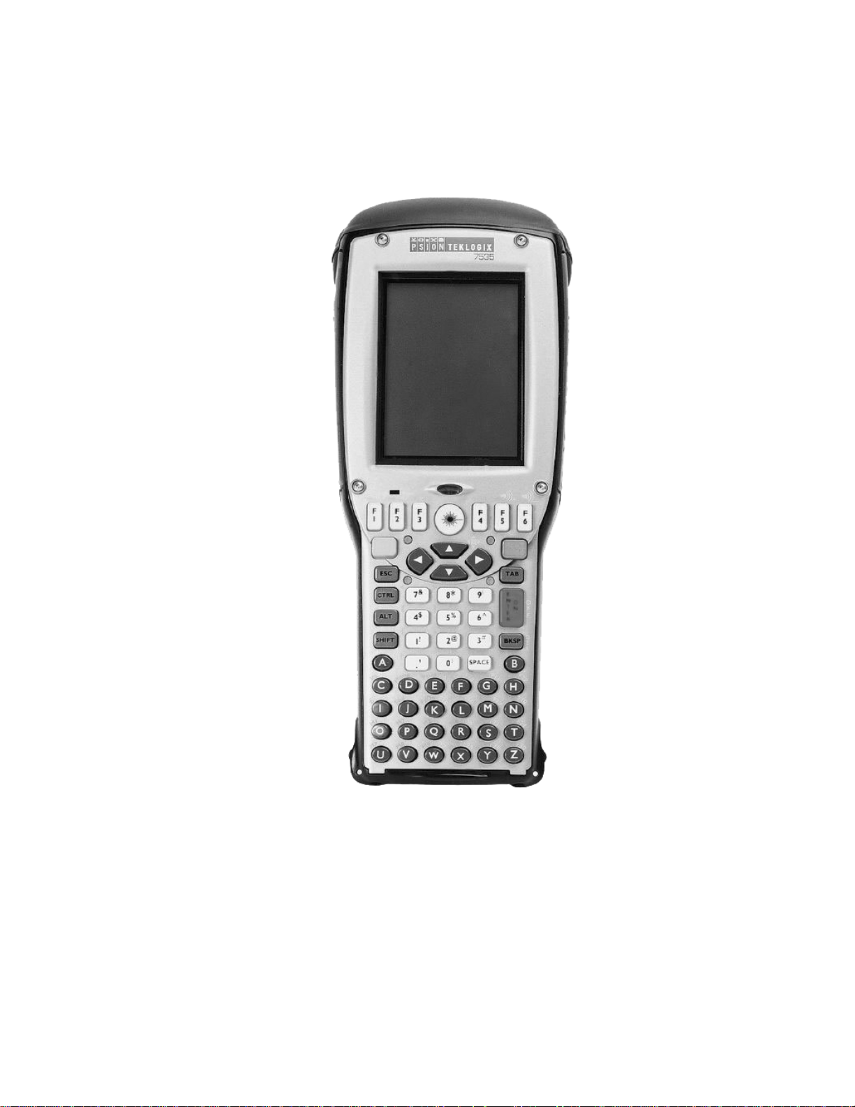
1.3.2 The 7535 Hand-Held Computer
Chapter 1: Introduction
The 7535 Hand-Held Computer
Figure 1.1 7535 With 58-Key Keyboard
Teklogix 7535 Hand-Held Computer User Manual 7
Page 28
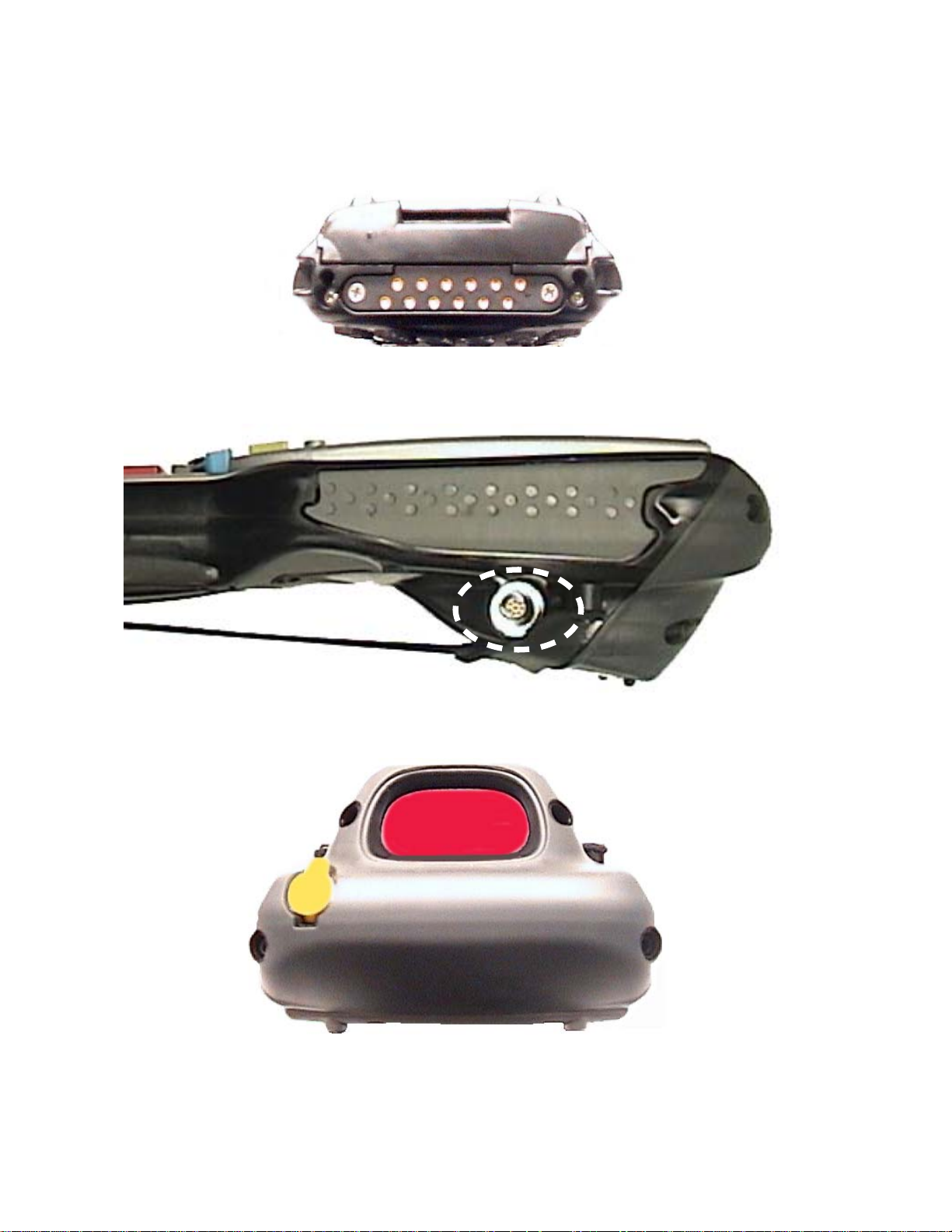
Chapter 1: Introduction
The 7535 Hand-Held Computer
Figure 1.2 7535 Docking Port
Figure 1.3 Tether Port
Figure 1.4 Scanner Window
8
Teklogix 7535 Hand-Held Computer User Manual
Page 29

1.3.3 The 7535 Hand-Held Safety Labels
Chapter 1: Introduction
The 7535 Hand-Held Safety Labels
Figure 1.5 Laser Warning Labels
Figure 1.6 Radio Labels
Teklogix 7535 Hand-Held Computer User Manual 9
Page 30
Chapter 1: Introduction
The 7535 Hand-Held Safety Labels
W arning: Using controls or adjustments or performing procedures other than
those specified herein may result in hazardous radiation exposure.
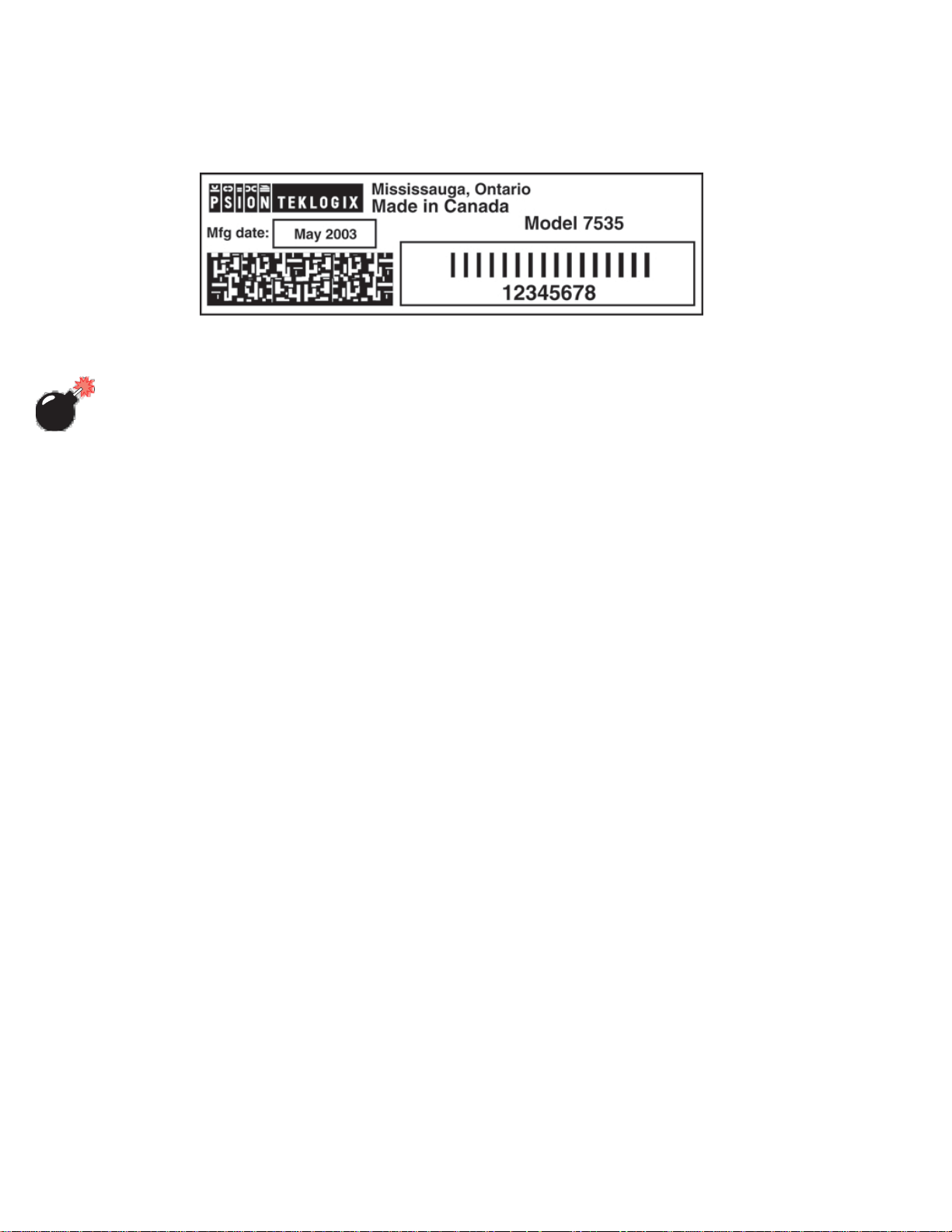
Figure 1.7 Manufacturer’s Label
10
Teklogix 7535 Hand-Held Computer User Manual
Page 31

UNPACKING & BASIC CHECKOUT 2
2.1 Preparing The 7535 For Operation .....................13
2.1.1 Equipment You Need To Get Started .................13
2.1.2 Charging The Battery.........................13
2.1.3 Attaching Carrying Accessories ...................13
2.1.3.1 Attaching The Hand Strap ..................14
2.1.3.2 Attaching The Pistol Grip ..................15
2.2 Powering Up The 7535 And Configuring The Radio ............16
2.2.1 Installing The Battery And Switching The 7535 On .........17
2.2.2 Configuring An IEEE 802.11 Radio .................18
2.3 Advanced NETWLAN Settings ....................22
2.3.1 Preferred Networks ......................23
2.3.2 Advanced Network Access ..................23
2.3.3 Configuring WEP Keys........................24
2.5 Checking The Scanner ...........................29
2.6 Uploading New Applications ........................29
2
2.8 Resetting The 7535 Hand-Held .......................30
2.7 Calibrating The Touchscreen ........................30
Teklogix 7535 Hand-Held Computer User Manual 11
Page 32

Page 33

Chapter 2: Unpacking & Basic Checkout
Preparing The 7535 For Operation
2.1 Preparing The 7535 For Operation
Typically, 7535 hand-helds are configured at the factory and arrive ready for use.
Although the 7535 is equipped with an internal Compact Flash and SD I/O slot,
these slots are not intended for user modification. If a device needs to be changed or
added in these slots, contact qualified Psion Teklogix personnel. Refer to
Appendix A: Support Services And Worldwide Offices for the service number
closest to you.
2.1.1 Equipment You Need To Get Started
You’ll need:
• A 7535 compatible battery charger , docking station or portable docking
module (PDM) with power supply.
• An operating wireless network (if you are not operating the equipment in
batch mode).
• A medium Phillips head screwdri v er.
2.1.2 Charging The Battery
Important: The 7535 uses a high capacity Lithium-Ion battery. It is critical
that you review the battery safety guidelines in “Lithium-Ion
Battery Safety Precautions” on page 208 before charging the
battery.
Batteries shipped from the factory are not charged. The y must be fully charged prior
to use. Full capacity may not be reached until at least 5 full charge/discharge c ycles
have been performed.
7535 batteries can be charged using a gang charger or the 7535 internal char ger.
When using the internal charger , a suitable power source is required. All chargers
and docking stations are described in Chapter 7: Peripher al Devices & Accessories
beginning on page 210.
2.1.3 Attaching Carrying Accessories
Psion Teklogix recommends that a carrying accessory – a hand strap, pistol grip or
shoulder strap – be installed on the 7535 before use.
If your hand-held is not fitted with a hand strap or pistol grip, you can install either
using the carrying accessory kit supplied. You’ll need:
• A Phillips head screwdri v er.
Teklogix 7535 Hand-Held Computer User Manual 13
Page 34

Chapter 2: Unpacking & Basic Checkout
Attaching The Hand Strap
Important: Do not use adhesives such as Loctite to secure the screws on the
carrying accessories. These chemicals may damage the plastic
casing.
2.1.3.1 Attaching The Hand Strap
Note: A Phillips head screwdriver is required.
Psion Teklogix recommends that the hand strap provided with your 7535 always be
used. Howe v er, if your unit has an internal scanner and you plan to use the pistol
grip accessory, a hand strap is not required.
Two Phillips head screws are provided with the hand strap.
• Attach the strap to the two threaded inserts located at the back of the 7535
near the top of the unit.
14
Figure 2.1 Attaching The Hand Strap
Teklogix 7535 Hand-Held Computer User Manual
Page 35

Chapter 2: Unpacking & Basic Checkout
Attaching The Pistol Grip
• Stretch the handstrap toward the base of the 7535, and hook the bottom of
the handstrap into the slot near the base of the battery pack.
Figure 2.2 Hooking The Hand Strap To The 7535
2.1.3.2 Attaching The Pistol Grip
Note: A Phillips head screwdriver is required.
The pistol grip is attached to the back of the 7535 using the four threaded inserts in
the upper part of the 7535 casing. Four black #4-40 Phillips head screws are
provided with this accessory.
Note: Prior to installation, make sure the trigger mechanism is securely
snapped into the pistol grip body and that the trigger operates properly.
Teklogix 7535 Hand-Held Computer User Manual 15
Page 36

Chapter 2: Unpacking & Basic Checkout
Powering Up The 7535 And Configuring The Radio
• Position the pistol grip so that it fits snugly over the back of the unit and
the inserts on the back of the 7535 align with the holes in the pistol grip.
Figure 2.3 Attaching The Pistol Grip
• Using a Phillips screwdri v er, securely fasten the pistol grip to the back of
the 7535.
2.2 Powering Up The 7535 And Configuring The Radio
Note: Psion Teklogix offers a Portable Docking Module (PDM) along with its
power supply to help speed the checkout and confirmation process for
your 7535. The PDM can power your hand-held with or without a battery
installed in the 7535. Refer to Chapter 7: Peripheral Devices & Accessories beginning on page 205 for more information about this accessory.
16
Teklogix 7535 Hand-Held Computer User Manual
Page 37

Chapter 2: Unpacking & Basic Checkout
Installing The Battery And Switching The 7535 On
2.2.1 Installing The Battery And Switching The 7535 On
If you are not using a docking station or PDM:
• Slide the charged battery with the moulded plastic facing you into the 7535.
Click the battery into place.
Figure 2.4 Installing The Battery
Note: If you are using a docking station, you can insert an uncharged battery,
dock the unit and switch it on.
If you are using a PDM, you can configure your unit without a battery , with
a charged battery or with an uncharged battery.
If you are using a hand strap:
• Hook the bottom of the hand strap into the slot at the base of the battery.
To switch the 7535 on:
• Press and hold down the <ENTER/ON> or the <SCAN> ke y for at least
one second.
• When all four LEDs flash orange, release the <ENTER/ON> button.
A splash screen displaying the Psion Teklogix logo and the Microsoft®
W indows® CE. net logo appears. When Windows® CE has successfully loaded, the
startup desktop is displayed.
Note: The screen may go blank for a few seconds after the splash scr een loading
bar reaches the end. This is part of the normal Windows CE cold boot
process. The desktop is displayed after a few moments.
Teklogix 7535 Hand-Held Computer User Manual 17
Page 38

Chapter 2: Unpacking & Basic Checkout
Configuring An IEEE 802.11 Radio
2.2.2 Configuring An IEEE 802.11 Radio
The most common 802.11b settings are configured as defaults. However, there are
some fields that must be completed, including the ESSID of your access point and
the security methods implemented in the network (including access keys). At
various stages during network setup, you can tap on the taskbar radio icon to view
detailed statistics such as the access point you are connected to, the radio strength,
and so on.
Important: If the 7535 is equipped with a radio and it has never been config-
ured, the radio settings dialogue box opens automatically when
the unit is powered on. Follow the directions beginning at Step 4
on page 19 to configure the radio.
After the initial configuration, you must follow the directions
beginning at Step 1 below to open the Control Panel and display
the radio settings dialogue box.
To configure the 802.11b radio:
1. Open the
icon on the desktop. If you’ re using a k e yboard, press <BLUE> <0>
and choose
2. Open the
Control Panel. If you hav e a touchscreen, tap on the Control Panel
Control Panel from the System Menu.
Network and Dial-up Connections applet.
18
Figure 2.5 Network And Dial-Up Connections
Teklogix 7535 Hand-Held Computer User Manual
Page 39

Chapter 2: Unpacking & Basic Checkout
Configuring An IEEE 802.11 Radio
3. Choose the
NETWLAN1 icon to open the 802.11b Wireless LAN Settings windo w.
Figure 2.6 802.11b Wireless LAN Settings Window
4. IP Address
In the IP Address tab, ‘Obtain an IP address via DHCP’ is selected by default.
This is the most common configuration. If you prefer, choose
IP address’,
and enter a static IP address.
‘Specify an
Figure 2.7 IP Address Assignment
Note: If you enter a static IP Address, press <TAB> to switch between the
address entry fields. Use the <LEFT> and <RIGHT> arrow keys to
position the cursor in an IP address field. (If you do not have a static
IP Address allocated to you, contact your System Administrator.)
Teklogix 7535 Hand-Held Computer User Manual 19
Page 40

Chapter 2: Unpacking & Basic Checkout
Configuring An IEEE 802.11 Radio
5. Wireless Networks
First, make certain that the check box next to ‘Use Windows to configure
network setting’
window are acti vated. If this option is not enabled, press <TAB> to
highlight the check box, and press <SPACE> to enable it.
List of networks
broadcasting ESSID
Preferred networks
is enabled (√) so that the items you configure in this
Figure 2.8 Radio Settings
6. ESSID (Extended Service Set Identifier)
Press the <TAB> key again to highlight the ‘Available networks...’ list, and
choose an access point that is broadcasting its ESSID. Since access
points are generally secure, they will most likely not be listed here;
you’ll need to define the access point to which your 7535 will connect.
Press the <TAB> key until the <Add...> b utton is highlighted. Press
<ENTER> to open the
Type the appropriate ESSID (Extended Service Set Identifier) in the
name
text entry field at the top of this dialogue box.
Wireless Network Properties dialogue box.
Type your access point’s
ESSID here.
Network
20
Figure 2.9 Wireless Network Properties
Teklogix 7535 Hand-Held Computer User Manual
Page 41

Chapter 2: Unpacking & Basic Checkout
Configuring An IEEE 802.11 Radio
The
Network name field can contain a maximum of 32 characters. The name
assigned here is listed in the preferred network list labelled
connect to these networks:’
Note: Keep in mind that the 7535 will only communicate with access points that
are configured with the same ESSID.
Ad Hoc And Infrastructure
7.
If you are using an “Infrastructure” network – one in which 7535s must
pass data through an access point – leave the checkbox ne xt to
ad h
oc network’ blank.
If you are using an “ Ad Hoc” netw ork – a network in which 7535s pass data
directly to other 7535s without an access point – press the <TAB> key to
highlight
the Ad Hoc check box.
‘This is an ad hoc network’, and press the <SP ACE> key to enable (√)
(see Figure 2.8 on page 20).
‘Automatically
‘This is an
8.
Saving The Configurations
In the Wireless Network Properties dialogue box, press the <TAB> ke y until
the <OK> button is highlighted. Press <ENTER> to sav e the configurations.
9. Once the
played, you need to save all your radio configurations. Press <TAB>
to highlight the
configuration.
10.
Reviewing The Configurations
To determine if the radio configuration has been successfully saved, in
the
Network and Dial-up Connections window (see Figure 2.6 on page 19),
choose the
window. Revie w the contents under each tab in the window to make
certain that your settings have been sa ved. To be sure that the unit is
communicating with an access point, check that the radio strength
meter in the taskbar is active.
To determine if you have successfully connected to the access point
network and have received an IP Address from the DHCP server, open the
NETWLAN Settings dialogue box (Figure 2.8 on page 20) is dis-
Wireless Networks tab, and press <ENTER> to sav e the
NETWLAN1 icon to redisplay the 802.11b Wireless LAN Settings
NETWLAN1 status window from the System Tray in the taskbar.
Teklogix 7535 Hand-Held Computer User Manual 21
Page 42

Chapter 2: Unpacking & Basic Checkout
Advanced NETWLAN Settings
Press <BLUE><0> and choose System Tray from the System Menu. Use the
<LEFT> and <RIGHT> arrow ke ys to highlight the radio strength meter
and then, press <ENTER>. The
Check that the “
Choose the <More...> button with the <RIGHT> or <LEFT> arrow k ey to
launch the
the unit IP Address. If you prefer, you can determine the unit IP Address
from the MS DOS command prompt located in the Windows folder in the
Explorer application. Type “ipconfig” in the command line to display your
IP Address.
Network Name” field displays the one you specified.
NETWLAN1 status window. Choose the IP Information tab to determine
2.3 Advanced NETWLAN Settings
This section describes a few additional options in the NETWLAN Settings dialogue box.
Keep in mind that these options are not necessary for radio configuration. All the
steps necessary for your radio to communicate with your network are detailed in
“Configuring An IEEE 802.11 Radio” beginning on page 18.
NETWLAN1 statistics window is displayed.
22
Preferred Networks
Figure 2.10 Radio Settings
Teklogix 7535 Hand-Held Computer User Manual
Move up &
Move down Buttons
Advanced
Button
Page 43

Chapter 2: Unpacking & Basic Checkout
Preferred Networks
2.3.1 Preferred Networks
Each network that you configure is listed in the preferred networks list under
‘Automatically connect to these networks’. These are the preferred networks that the 7535
attempts to connect with in sequence, be ginning at the top of the list. If you need to
rearrange this list of networks – move netw orks up and down in the list:
• Press the <TAB> key to highlight the preferred networks list.
• Use the <UP> or <DOWN> arrow keys to highlight the network in the
preferred list that you want to move up or down.
• T o mo ve the highlighted item in the list upward or do wnward, press <TAB>
to highlight the <Move u
• Press <ENTER> to move the item up or do wn in the preferred netw ork list.
p> or <Move do wn> button.
2.3.2 Advanced Network Access
If you have configured more than one netw ork, the <Advance> b utton in the NETWLAN
Settings
your 7535 can access.
dialogue box (Figure 2.10 on page 22) is used to specify the type of network
To access the Advance dialogue box:
1. Press the <TAB> key to highlight the <Adv
<ENTER>.
Figure 2.11 Advanced Network Settings
ance> button, and press
Teklogix 7535 Hand-Held Computer User Manual 23
Page 44

Chapter 2: Unpacking & Basic Checkout
Configuring WEP Keys
These options specify the type of network connection your 7535 will choose
from the preferred network list labelled
(see Figure 2.10 on page 22).
‘Any available network (AP preferred)’ – connect to an infrastructure network or an
ad hoc network listed in the preferred network list.
‘Access point (infrastructure) only’ – connect to an infrastructure network listed in
the preferred network list.
‘Computer-to-computer (ad hoc) only’ – connect to an ad hoc (peer-to-peer) network
listed in the preferred network list.
‘Automatically connect to non-preferred networks’ – connect to an infrastructure
network not listed in the preferred network connection list.
2. When you’ve made your selections, press <TAB> to highlight the
<Close> button, and press <ENTER>.
‘Automatically connect to these networks:’
2.3.3 Configuring WEP Keys
To set up WEP (Wired-Equivalent Pri vacy) encryption to prevent others from
accidentally accessing your network, follow the steps in this section.
1. Open the
2. Open the
Control Panel.
Network and Dial-up Connections applet.
Figure 2.12 Network And Dial-Up Connections
24
Teklogix 7535 Hand-Held Computer User Manual
Page 45

Chapter 2: Unpacking & Basic Checkout
Configuring WEP Keys
3. Choose the
Figure 2.13 802.11b Wireless LAN Settings Window
NETWLAN1 icon to open the 802.11b Wireless LAN Settings windo w.
Figure 2.14 Radio Settings
Teklogix 7535 Hand-Held Computer User Manual 25
Page 46

Chapter 2: Unpacking & Basic Checkout
Configuring WEP Keys
4. Display the options under the Wireless Network tab . If it’ s not displayed, use
the <TAB> key to highlight the left-most tab in the
logue box –
options under the
Preferred Networks
IP Address. Press the <RIGHT> arrow ke y to display the
Wireless Network tab .
NETWLAN Settings dia-
Figure 2.15 Wireless Networks Tab
5. Press the <TAB> key to highlight the <Add..> b utton, and press
<ENTER> to display the
Wireless Network Properties dialogue box.
√
Modify WEP Ke
Figure 2.16 Wireless Network Properties
26
Teklogix 7535 Hand-Held Computer User Manual
Page 47

Chapter 2: Unpacking & Basic Checkout
Configuring WEP Keys
Important: To add or modify a WEP Key in an EXISTING
• In the ‘preferred network’ list (see Figure 2.15 on page 26),
highlight the network in which you want to add or modify a
WEP key, and then
• RATHER THAN SELECTING THE <Add...> BUTTON,
select the <Properties> button.
6. Press <TAB> until
<SPACE> k ey to enable (√) this option.
7. To define your own WEP k eys, press the <TAB> key to highlight
‘Data encryption (WEP enabled)’ is highlighted. Press the
network:
‘The key is provided automatically’. Press <SPACE> to deselect the checkbox.
8. Press the <TAB> key to highlight the <Modify WEP Keys...> button,
and press <ENTER>.
Figure 2.17 WEP Key Settings
9. Press the <TAB> key to move from field to field in this dialogue box.
Network key: Used to specify a 5 or 13 ASCII character sequence or an equiv-
alent 10 or 26 Hexadecimal digit sequence that matches the activ e WEP k ey
on the access point.
Teklogix 7535 Hand-Held Computer User Manual 27
Page 48

Chapter 2: Unpacking & Basic Checkout
Additional Radio Security Options
Key format: Defines the format WEP keys used – either ASCII alphanumeric
characters or Hexadecimal digits. For example, if the access point has an
active k ey of
and the
bobby, the 7535 Key format would be set to ‘ASCII characters’
Network key would be defined as bobby.
Key length: Defines the length of the keys as either 104 bits/13 characters or
40 bits/5 characters. (Intel radios support both these lengths. Other radios
may be restricted.)
Key Index (advanced): Identifies the WEP key. Up to 4 ke ys can be inde xed.
Keep in mind that
if an access point and a hand-held have been assigned a T ransmit K ey of
Windo ws CE will match that with
hand-held have been assigned a Transmit Key of
match that with
10. Press <TAB> to highlight the <OK> button, and press <ENTER>.
Key Index numbering for Windo ws CE starts at 0 (zero), so
Key Index 3, and so on.
1,
Key Index 0 (zero). If an access point and a
4, Windows CE will
2.4 Additional Radio Security Options
Additional security options can be set through the Wireless Network Properties dialogue
box.
Figure 2.18 Network Authentication, EAP and 802.1X
28
Network Authentication (Shared Mode)
If ‘Network Authentication’ is enabled (√), the access point sends a known unen-
crypted challenge packet to the 7535 radio which encrypts the packet and
sends it back to the access point. The access point attempts to decrypt the
Teklogix 7535 Hand-Held Computer User Manual
Page 49

encrypted packet and forwards an authentication response packet back to
the 7535 radio, indicating the success or failure of the decryption. If the
packet is successfully encrypted/decrypted, the user is authenticated.
If this option is disabled (the default setting), network authentication is
not used.
EAP (Extensible Authentication Protocol) and Enable 802.1x
“802.1x” is the IEEE standard that offers additional security for local area
networks. It provides authentication for user de vices attached to an Ethernet
network, whether wired or wireless. A packet encapsulated in an “EAP” is
used in conjunction with the “802.1x” standard to authenticate users at the
MAC layer.
Chapter 2: Unpacking & Basic Checkout
Checking The Scanner
Available EAPs are listed in the dropdown menu ne xt to the
To enable “802.1x”, press <TAB> to highlight
<SPACE> k ey to enable (√) it.
‘Enable 802.1x’, and press the
‘EAP’ option.
2.5 Checking The Scanner
If your 7535 is equipped with an internal scanner, it will successfully decode most
1D bar codes as delivered. Press the SCAN button and check for a valid decode on
any UPC bar code. If desired, set the “Dot T ime” parameter to zero in the ‘Teklogix
Scanners’ applet in the
Performance is improved if you disable all unneeded bar codes under the ‘Bar
Codes’ dialogue screen. Review “Scanner Properties” on page 86 for details about
bar codes.
Control Panel to turn off the def ault aiming dot.
2.6 Uploading New Applications
The simplest way to upload Windows CE.net applications into the 7535 is to use a
PDM with a USB equipped PC. Refer to “Portable Docking Module (PDM)” on
page 219 for more details about the PDM.
• Attach the supplied USB cable between the host port on your PC and the
PDM ‘device’ port.
• Install the PDM on the 7535 and turn it on.
Teklogix 7535 Hand-Held Computer User Manual 29
Page 50

Once WinCE is booted, the PC should indicate it has found a new USB storage
device. (You will need the Windows 2000 operating system or later).
[Final details TBD]
To upload an application:
• Drag the file onto the USB device folder.
• Shut down the USB de vice on the PC before disconnecting the 7535.
• Perform a cold reboot of the 7535 – hold down the <ENTER> and
<BLUE> keys for at least a second.
2.7 Calibrating The Touchscreen
If your 7535 is equipped with a touchscreen, it will need to be calibrated. Refer to
“Calibrating The Touchscreen” on page 44 for details.
2.8 Resetting The 7535 Hand-Held
Note: You do not need to reset your 7535 after configuring the radio.
To reset the 7535:
• Press and hold down the <BLUE> ke y and the <ENTER/ON> k e y simultaneously for a minimum of six seconds.
A reset results in a complete reboot of the unit. All RAM memory contents are lost.
The contents of the flash memory and memory card are preserved.When the 7535 is
reset, the screen displays the Psion Teklogix and Microsoft® Windows® CE.net
splash screen before displaying the startup desktop.
Page 51

GETTING TO KNOW YOUR 7535 3
3.1 Features Of The 7535 ............................33
3.2 The Battery .................................34
3.2.1 Battery Safety.............................34
3.2.2 Removing And Installing The Battery Pack .............34
3.2.3 Charging The Battery.........................35
3.3 Switching The 7535 Hand-Held On And Off ................36
3.4 The Keyboard ................................37
3.4.1 Modifier Keys.............................38
3.4.1.1 Activating Modifier Keys..................39
3.4.1.2 Locking Modifier Keys...................39
3.4.2 The Keys ...............................39
3.4.3 The 58-Key Keyboard ........................40
3.4.4 The 36-Key Keyboard ........................40
3.4.5 The Keypad Backlight ........................42
3.5 The Display .................................43
3.5.1 Adjusting The Display Backlight ...................43
3.5.2 Adjusting The Contrast On Monochrome Displays .........43
3.5.3 Calibrating The Touchscreen .....................44
3
3.6 7535 Hand-Held Computer Indicators ...................45
3.6.1 LEDs .................................45
3.6.1.1 Charge LEDs.........................46
3.6.1.2 Radio Traffic LEDs.....................46
3.6.1.3 Scan LEDs ..........................47
3.6.2 Onscreen Indicators..........................47
3.6.3 Audio Indicators ...........................49
3.6.3.1 Adjusting The Beeper Volume................49
3.7 Internal Scanners ..............................50
3.7.1 Warnings ...............................51
3.7.2 Scanning Techniques .........................51
3.7.3 Scan LED Indicators .........................52
3.7.4 Troubleshooting............................52
3.7.5 Operating One Dimensional (1D) Internal Laser Scanners......53
3.7.6 Operating Internal PDF Laser Scanners ...............53
3.7.7 Operating Internal Two Dimensional (2D) Imager Scanners.....53
Teklogix 7535 Hand-Held Computer User Manual 31
Page 52

Chapter 3: Getting To Know Your 7535
3.8 Connecting & Disconnecting Tethered Peripherals .............54
3.9 Monitoring The Battery And Maximizing Run Time ............55
3.10 Monitoring The Network Connection ...................57
3.11 Uploading Data In A Docking Station ...................57
3.12 General Maintenance............................58
3.12.1 Caring For The Touchscreen.....................58
3.12.2 Cleaning The 7535..........................58
32
Teklogix 7535 Hand-Held Computer User Manual
Page 53

3.1 Features Of The 7535
7535 Screen
Ambient Light Sensor
Chapter 3: Getting To Know Your 7535
Features Of The 7535
Tether Port
Stylus
(Pointing Tool)
Docking Port
Figure 3.1 Front Of 7535
Scanner Window
Battery Pack
Tether Port
Figure 3.2 Back Of 7535
Teklogix 7535 Hand-Held Computer User Manual 33
Page 54

Chapter 3: Getting To Know Your 7535
The Battery
3.2 The Battery
The 7535 hand-held operates with a Lithium-Ion battery pack. Preparing the
hand-held unit for operation requires that a battery pack be charged and installed in
the unit.
3.2.1 Battery Safety
Important: Before attempting to install, use or charge the battery pack, it is
critical
in the section entitled “Lithium-Ion Battery Safety Precautions”
beginning on page 208.
3.2.2 Removing And Installing The Battery Pack
Note: TURN OFF THE 7535 HAND-HELD BEFORE REMOVING THE
BATTERY PACK. If you do not turn the hand-held off before removing
the battery, it may be necessary to reboot the unit. Any active sessions
will be lost.
that you review and follow the important safety guidelines
Removing The Battery Pack
• If your 7535 is equipped with a hand strap, unhook it from the base of the
battery.
• Press down the release tab at the top of the battery, and slide the battery out.
34
Teklogix 7535 Hand-Held Computer User Manual
Page 55

Chapter 3: Getting To Know Your 7535
Installing The Battery Pack
To install the battery pack:
• Slide the battery pack with the moulded plastic facing you into the 7535.
Click the battery into place.
Charging The Battery
Figure 3.3 Installing The Battery Pack
• If your computer is equipped with a hand strap, insert the hook at the end of
the hand strap into the slot at the base of the battery.
3.2.3 Charging The Battery
Important: FOR DETAILED INFORMATION about 7535 chargers and
docking stations, refer to Chapter 7: Peripheral Devices & Acces-
sories beginning on page 205.
All batteries must be charged before use. The 7535 battery can be char ged with a
variety of chargers. These include:
• 6-Gang Charger (Model #HU3006) – charges up to six Lithium-Ion batter ies at one time.
• Portable Docking Module (PN 1030085) – charges the 7535 battery (with
the battery installed in the unit).
• Combo Charger (Model #HU3002) – a desktop charger that char ges the
7535 internal battery along with a spare battery pack.
Teklogix 7535 Hand-Held Computer User Manual 35
Page 56

Chapter 3: Getting To Know Your 7535
Switching The 7535 Hand-Held On And Off
• Combo Docking Station (Model #HU4002) – operates as both a charger
and a docking station. Operating as a charger , both the battery installed in
the computer and a spare battery can be charged simultaneously . When used
as a docking station, it provides connectivity (10/100 BaseT Ethernet interface) to a host Ethernet network, primarily for batch data file transfers.
• Quad Docking Station (Model #HU4004) – can charge the battery of up to
four 7535s inserted in the docking station while transferring data through an
Ethernet connection.
• Powered Cradle – can charge the 7535 with the battery installed in the
hand-held.
It can take from 1.5 to 4 hours to charge a battery. The 7535’s intelligent charging
system protects the battery from over -char ging by terminating the charge process
when the battery is at maximum capacity.
Note: Refer to “Monitoring The Battery And Maximizing Run Time” on page 55
for additional information about the 7535 battery.
Important: To avoid damaging the battery, c hargers will not begin the charge
process until the battery temperature is between 0˚C (32˚F) and
39˚C (102˚F). If the battery is too hot or cold, the battery status
LED flashes yellow and the charge is suspended. Refer to
Table 3.1, “Charge LEDs” on page 46 for details.
3.3 Switching The 7535 Hand-Held On And Off
Switching On The 7535
• Press and hold down the <ENTER/ON> ke y for at least one second.
• When all four LEDs flash orange, release the <ENTER/ON> button.
A splash screen displaying the Psion Teklogix logo and the Microsoft®
W indows® CE. net logo appears followed by the startup desktop.
Note: If the 7535 is in suspend state, pressing any key ‘wakes’ the unit from this
state. The screen in which you were working before the computer entered
suspend state is displayed.
36
Teklogix 7535 Hand-Held Computer User Manual
Page 57

Chapter 3: Getting To Know Your 7535
The Keyboard
Switching Off The 7535
Important: Keep in mind that turning off the 7535 does not result in a
complete reboot; rather, the unit enters a power-saving,
“suspend” state. When the 7535 is turned on from suspend state,
operation resumes within a few seconds.
To switch off the 7535:
• Press the <BLUE> key, and then press the <ENTER/ON> key.
Important: If the word ‘BLUE’ is displayed in uppercase
at the bottom of the screen, this key is locked “on” – the 7535 will
not switch off. Press the <BLUE> key again to unlock it; then
press <BLUE> <ENTER/ON> to switch the 7535 off.
in the taskbar area
3.4 The Keyboard
The 7535 offers two types of keyboard layouts – a 58-key keyboard and a 36-ke y,
large button keyboard. Most of the keys on these keyboards operate much like a
desktop computer . Where a key or key function is not consistent with the PC
keyboard, the dif ferences are noted.
The <BLUE> and <ORANGE> modifier keys pro vide access to additional keys and
system functions. These functions are colour coded in orange and blue print above
the keyboard ke ys.
Teklogix 7535 Hand-Held Computer User Manual 37
Page 58

Chapter 3: Getting To Know Your 7535
Modifier Keys
F11 F12
F1 F2
CTRL
ABC DEF
!
1
GHI JKL MNO
$
4
PQRS TUV WXYZ
&
7
SPACE
'
.
+
F15 F16 F17
__
__
@
2
5
8
_
_
MENU
0
%
*
)
SHIFT ALT
-
#
3
6
9
F5 F6 F7 F8
F19
M5 M6
F9 M1 M2 F10
F13 F14
F3
TAB
E
N
T
E
R
^
DEL
(
BKSP
F18
F20M3 M4
F4
E
S
C
O
O
N
F
F
38
Figure 3.4 58-Key And 36-Key Keyboard Layouts
3.4.1 Modifier Keys
The <SHIFT>, <CTRL>, <ALT>, <BLUE> and <ORANGE> keys are modifier
keys. Pressing a modifier key changes the function of the next key pressed. For
example, on a 58-key k eyboard, a square bracket is printed in or ang e print abo ve the
<4> key. Pressing the <ORANGE> key follo wed by the <4> k ey displays a square
bracket rather than the number 4.
The <SHIFT>, <CTRL> and <ALT> keys operate much like a desktop k e yboard
except that they are not chorded (two k eys held do wn simultaneously). The modifier
key must be pressed first followed by the key whose function you want modified.
Teklogix 7535 Hand-Held Computer User Manual
Page 59

Chapter 3: Getting To Know Your 7535
Activating Modifier Keys
3.4.1.1 Activating Modifier Keys
When a modifier key is pressed once, it is displayed in lowercase letters in the
taskbar at the bottom of the 7535 screen. For example, if the <CTRL> ke y is
pressed,
pressed, the modifier key becomes inactive and disappears from the taskbar.
ctrl key is displayed at the bottom of the unit screen. Once the next key is
3.4.1.2 Locking Modifier Keys
When a modifier key is pressed twice, it is ‘locked’ on. A ‘locked’ modifier key is
displayed in uppercase letters in the taskbar . For example, pressing the <BLUE> ke y
twice locks it on – it is displayed as BLUE KEY in the taskbar at the bottom of the
computer screen.
The locked modifier key will remain active until it is pressed a third time to unlock
or turn it off. Once a modifier key is unlocked (pressed a third time), the uppercase
representation at the bottom of the screen is no longer displayed.
3.4.2 The Keys
The <SHIFT> Key
The <SHIFT> key is used to display uppercase alpha characters. A ‘locked’
<SHIFT> key (pressed twice) operates like the <CAPS LOCK> key on a desktop
keyboard.
The Arrow Keys
The Arrow keys move the cursor around the screen in the direction of the arrow –
up, down, left and right. The cursor is the flashing box or underline character that
indicates where the next character you type will appear.
The <BKSP/DEL> Key
The <BKSP> key (sometimes referred to as destructi v e backspace) moves the
cursor one character to the left, erasing the incorrectly entered key stroke.
The <DEL> key (<BLUE> <BKSP>) erases the character at the cursor position.
The <CTRL> And <ALT> Key
The <CTRL> and <ALT> keys modify the function of the next k ey pressed and are
application dependent.
Teklogix 7535 Hand-Held Computer User Manual 39
Page 60

Chapter 3: Getting To Know Your 7535
The 58-Key Keyboard
The <TAB> Key
Typically, the <TAB> key moves the cursor to the ne xt field to the right or
downward.
The <ESC> Key
Generally, this key is used as a keyboard shortcut to close the current menu,
dialogue box or activity and return to the pre vious one.
The <SPACE> Key
Pressing this key inserts a blank space between characters. In a Windows dialogue
box, pressing the <SPACE> k ey enables (√) or disables a checkbox.
The <SCAN> Key
Pressing the <SCAN> key – the yello w k e y with the star-burst scan symbol on it –
activ ates the scanner beam while pressed. F or units that do not have internal
scanners, this key is either inoperable or can be remapped to another ke y function
(such as an <ENTER> key).
3.4.3 The 58-Key Keyboard
In addition to alphanumeric keys that are directly accessible on the ke yboard (no key
combination is required) and the keys described in this chapter , the 58-ke y keyboard
also provides function keys and macro k e ys. These keys are not used as part of the
Windows CE operating system. They can be custom defined for each application.
The Tekterm application utilizes these keys. Refer to “Additional K e yboard
Functions” on page 113 for details about Tekterm keys.
3.4.4 The 36-Key Keyboard
On 36-key 7535s, all alpha characters are printed on the unit plastic in orang e
typeface above the numeric k e ys. To access an alpha character, you must first press
the <ORANGE> key and then press the numeric ke y abo ve which the alpha
character you want to type is printed.
Because the alpha keys on a 36-ke y k e yboard are laid out much lik e the letters on a
telephone – generally in groups of three letters per numeric key – you need to take a
few extra steps to access the alphabetic characters. The examples in this section help
illustrate how to access alpha characters.
40
Teklogix 7535 Hand-Held Computer User Manual
Page 61

Chapter 3: Getting To Know Your 7535
The 36-Key Keyboard
Choosing A Single Alpha Character
The examples below illustrate how to access A, B and C, all of which are printed in
orange characters abov e the numeric k ey, <2>.
To choose the letter ‘a’:
• Press the <ORANGE> key, and press the numeric key <2>.
To choose the letter ‘b’:
• Press the <ORANGE> key twice to lock it ‘on’, and press <2> twice.
• Press the <ORANGE> key again to unlock or turn it off.
To choose the letter ‘c’:
• Press the <ORANGE> key twice to lock it ‘on’.
• Press <2> three times, and then
• Press the <ORANGE> key again to unlock or turn it off.
Creating Uppercase Letters
To display a capital letter:
• Press the <ORANGE> key and then the <SHIFT> ke y bef ore typing the
alpha character .
Choosing More Than One Alpha Character From The Same Key
If you need to choose more than one alpha character from a single key, you’ll need
to press the ‘Accept’ key between alpha selections. The ‘Accept’ key is presented as
an arrow ⇒ symbol abov e the ‘0’ (zero) key. Pressing this k ey signals the 7535 to
display the alpha character you’ v e chosen and await the next selection from the
same key.
For example, suppose you want to type the letters ‘a’, ‘b’ and ‘c’. These letters are
all accessible from the numeric key, <2>.
To type the letter ‘a’:
• Press the <ORANGE> key twice to lock it ‘on’, and then press the numeric
key, <2>.
• Press the ‘Accept’ key < ⇒> to indicate that the letter ‘a’ should be
accepted and that another letter from the same key will be chosen.
Teklogix 7535 Hand-Held Computer User Manual 41
Page 62

Chapter 3: Getting To Know Your 7535
The Keypad Backlight
To type the letter ‘b’:
• Press the <2> key twice.
• Press < ⇒> to accept the letter ‘b’.
To type the letter ‘c’:
• Press the <2> key three.
When you have completed your alpha selections fr om this k ey, you can do one of the
following:
• If you want to choose additional alpha characters from another key(s),
leave the <ORANGE> key ‘on’, and press the next numeric key that
supports the alpha character you require.
• If you do not want to choose any additional alpha characters, press
<ORANGE> again to unlock or turn ‘off’ the k e y and end alpha selection.
Choosing Multiple Alpha Characters From A Range Of Keys
If you plan on choosing alpha characters from a number of different ke ys, you are
not required to press the ‘Accept’ < ⇒> key after each alpha selection. The < ⇒>
key is only required when you are choosing more than one alpha character from the
same key – e.g., ‘a’, ‘b’ and ‘c’ from the <2> key.
Suppose you want to type the letters ‘a’, ‘d’ and ‘g’. These alpha characters are
accessed from the numeric keys <2>, <3> and <4>.
• With the <ORANGE> key locked ‘on’ (press twice), press <2> to type the
letter ‘a’.
• Press <3> to type ‘d’, and press <4> to type the letter ‘g’.
• To end alpha selection, press the <ORANGE> key a third time to unlock it.
3.4.5 The Keypad Backlight
The intensity of the keypad backlight and the conditions under which this backlight
is activ ated can be configured using the Keyboard icon in the Windows CE Control Panel.
The behaviour of the keypad backlight is tailored in the Keyboard Properties dialogue box.
Refer to “Keyboard Backlight” on page 81 for details about this option.
Note: Keep in mind that this option may be restricted to supervisory use only.
42
Teklogix 7535 Hand-Held Computer User Manual
Page 63

Chapter 3: Getting To Know Your 7535
The Display
3.5 The Display
7535s are equipped with display backlighting to improve character visibility in lo w
light conditions. The unit switches on when a key is pressed and the ambient light is
below the set threshold. A light sensor on the front of the hand-held determines the
ambient light level. On some displays, the contrast can also be adjusted to further
improve character visibility.
3.5.1 Adjusting The Display Backlight
The behaviour of the display backlight – the ambient light threshold below which
the backlight will become active and the intensity of the backlight – can be specified
in the Display Properties dialogue box in the Windows CE Control Panel.
Note: Refer to “Display Backlight” on page 77 for details about the Display
Properties dialogue box.
3.5.2 Adjusting The Contrast On Monochrome Displays
Note: In addition to the manual adjustments described in this section, the dis-
play contrast can also be adjusted using the Windows CE Control Panel.
Refer to “Display Contrast” on page 77 for details about this dialogue
box.
On monochrome displays only, the display contrast can be adjusted from the unit
keyboard using the <BLUE> ke y and function k e ys <F1> and <F2>.
To darken the display:
• Press the <BLUE> key, and then press <F1> . Repeat this key combi-
nation until the contrast suits your needs. To work more efficiently with
these keys, refer to the note below.
To lighten the display:
• Press the <BLUE> key, and then press <F2> . Repeat this key combi-
nation until the contrast suits your needs. To work more efficiently with
these keys, refer to the note below.
Note: To adjust the display contrast quickly, lock the <BLUE> key “on” by
pressing it twice. You can then press the <F1> and <F2> function keys
until you can easily read the contents of the screen.
When you have satisfactorily adjusted the contrast, pr ess the <BLUE> k ey
a third time to unloc k or turn it off.
Teklogix 7535 Hand-Held Computer User Manual 43
Page 64

Chapter 3: Getting To Know Your 7535
Calibrating The Touchscreen
3.5.3 Calibrating The Touchscreen
If your 7535 touchscreen has never been calibrated or if you find that the stylus
pointer is not accurate when you tap on an item, use the Stylus Properties dialogue box in
the Windo ws CE Control Panel to recalibrate the screen.
• In the Control Panel, choose the Stylus icon to display the Stylus Properties window.
Figure 3.5 Stylus Icon
• Select the Calibration tab, and then choose the ‘Recalibrate’ button.
Figure 3.6 Calibration Screen
• Follow the directions on the calibration screen to calibrate the screen.
44
Teklogix 7535 Hand-Held Computer User Manual
Page 65

Chapter 3: Getting To Know Your 7535
7535 Hand-Held Computer Indicators
3.6 7535 Hand-Held Computer Indicators
7535s use LEDs (Light Emitting Diode), onscreen messages and audio tones as
indicators.
3.6.1 LEDs
The 7535 is equipped with four tri-coloured LEDs. This section outlines what these
LEDs indicate.
Important: If an LED is illuminated in red, the operator should be cautious
as this generally indicates an abnormal operating condition or
active laser emission.
Radio Traffic
LED
Scanner
LED
User
Application
LED
Charge
LED
Figure 3.7 Keyboard LEDs
Teklogix 7535 Hand-Held Computer User Manual 45
Page 66

Chapter 3: Getting To Know Your 7535
Charge LEDs
3.6.1.1 Charge LEDs
The lower-right LED is reserved for internal charger/power status. This indicator is
active e v en when the 7535 is inserted in a docking station (and in suspend mode) so
that the charge status of the battery can be detected easily.
Function Charge LED Behaviour
External power not available. LED off.
Fully charged to within 95% of charge
capacity.
Quick charge successfully completed to
within 75% of charge capacity.
Charge in progress. LED displays solid yellow colour.
Cell temperature out of range for charge. LED flashes yellow.
Unable to charge battery. LED displays solid red colour .
Charge circuit failure.* LED flashes fast red.*
LED displays solid green colour .
LED flashes slow green.
*If the charge fails, refer to the charger troubleshooting sections in Chapter 7: P eripher al Devices &
Accessories beginning on page 210 for helpful details.
Table 3.1 Charge LEDs
3.6.1.2 Radio Traffic LEDs
The upper-left LED on your 7535 flashes either orange or green to indicate when the
radio transmits and receives data.
Note: Keep in mind that while the standard 802.11b radio supports the trans-
mit/receive LED, not all radios support this function.
Function Radio Traffic LED Behaviour
Radio Transmit LED flashes orange.
Radio Receive LED flashes green.
Table 3.2 Transmit and Receive LEDs
46
Teklogix 7535 Hand-Held Computer User Manual
Page 67

Chapter 3: Getting To Know Your 7535
Scan LEDs
3.6.1.3 Scan LEDs
Successful scans are indicated in two ways – with a scan LED and with an
audio tone.
Function Scan LED Behaviour
Scan in progress LED displays solid red during scan.
Successful scan
Unsuccessful scan LED flashes red.
LED displays solid green after decode.
Off when scan ended.
Table 3.3 Scan LED
3.6.2 Onscreen Indicators
The taskbar at the bottom of the screen displays a variety of system status indicators.
Figure 3.8 Taskbar
This display changes dynamically, and only those icons that are applicable are
displayed. For example, if a radio is not installed in your 7535, the radio signal icon
is not displayed in the taskbar .
Teklogix 7535 Hand-Held Computer User Manual 47
Page 68

Chapter 3: Getting To Know Your 7535
Onscreen Indicators
Modifier Key Indicators
<SHIFT>, <CTRL>, <ALT>, <BLUE> and <ORANGE> are modifier keys that
have onscreen indicators to sho w when a ke y is acti v e or locked. If a modifier k ey is
pressed once to activ ate it, the key is displayed in the taskbar in lowercase characters
– for example, pressing the <BLUE> key once displays blue key in the taskbar . If a
modifier key is pressed twice, it is ‘locked on’ and the onscreen indicator is
displayed in uppercase letters in the taskbar – for e xample, pressing <BLUE> twice
displays BLUE KEY in the taskbar .
Battery Gauge
The battery shaped icon displayed in the taskbar provides a visual indication of the
remaining battery power. The icon acts as a meter that is either full, at three-quarter
level, half, quarter level or empty.
When the battery level is low – approximately 15 minutes from empty – a warning
window pops up. When the battery power is completely depleted, a final warning
window indicates that the 7535 will be po wered down.
Full 75% 50% 25% Empty
Radio Signal Quality
Increasing radio signal quality is represented by longer, filled bars within this icon.
100%
Link Broken
Tethered Devices
When a peripheral is attached to the tether port and activ ated, an associated icon
appears in the taskbar . The sample to the left indicates that a USB device is
connected to the tether port.
Scanner RFID Serial Device Scan-SeeUSB Device
48
Teklogix 7535 Hand-Held Computer User Manual
Page 69

Chapter 3: Getting To Know Your 7535
Audio Indicators
Docking Device
When a 7535 is inserted in a docking station, charger or cradle, an associated icon
appears in the taskbar .
Gang Charger, Combo Charger
Combo Docking & Docking Station
Quad Docking Station Power Cradle Portable Docking
Module (PDM)
Security Level
Security levels can be set to limit access to the Windo ws CE operating system. In
addition, applications can be restricted to prevent inadv ertent changes.
3.6.3 Audio Indicators
The 7535 beeper provides a variety of sounds and can be configured to emit a sound
when a key is pressed, a ke yboard character is rejected, scan input is accepted or
rejected, an operator’ s entry does not match in a match field or the battery is low .
3.6.3.1 Adjusting The Beeper Volume
The volume function keys located along the top of the k eyboard are used to adjust
the beeper volume emitted from your 7535. The increase volume function key is
labelled with a plus sign . The decrease volume k e y is labelled with a minus
sign .
On 58-key keyboards, the volume function k e ys are accessed by pressing
<BLUE> <F5> and <F6>.
On 36-key keyboards, the volume function k e ys are accessed by pressing
<BLUE> < F3> and <F4>.
To increase the beeper volume:
• Press the <BLUE> key and then, the increase volume function key .
Repeat this key combination until the volume is sufficient for your needs.
To work more efficiently with these k eys, refer to the note on page 50.
Teklogix 7535 Hand-Held Computer User Manual 49
Page 70

Chapter 3: Getting To Know Your 7535
Internal Scanners
To decrease the beeper volume:
• Press the <BLUE> key and then, press the decrease volume function
key . Repeat this key combination until the volume is low enough for
your needs. To work more efficiently with these keys, refer to the note
below.
Note: To adjust the beeper volume more quic kly, lock the <BLUE> key “on” by
pressing it twice . You can then press the appropriate volume function keys
until the beeper volume suits your needs.
When you have satisfactorily adjusted the beeper volume, press the
<BLUE> key a third time to unlock or turn it off.
3.7 Internal Scanners
The scanner installed in your unit can be configured using the Scanner Properties
dialogue box in the Control Panel.
The 7535 can be equipped with a:
• One dimensional (1D) internal laser scanner,
• Internal PDF laser scanner, or a
• Two dimensional (2D) internal imager scanner.
It is critical that you revie w the warnings listed in Section 3.7.1 on page 51 before
using any of the scanners described in this chapter. “Scanning Techniques” on
page 51 outlines the mechanics of a successful scan. In addition, review “Scan LED
Indicators” on page 52 to better understand how to interpret whether or not a bar
code has been successfully scanned. Finally, “Troubleshooting” on page 52
provides some helpful suggestions should the scan fail.
50
Teklogix 7535 Hand-Held Computer User Manual
Page 71

Chapter 3: Getting To Know Your 7535
3.7.1 Warnings
For your own safety, it is critical that you comply with the following w arnings:
1. Do not look into the laser beam or point the beam at people
or animals.
2. CAUTION – Using controls or adjustments, or performing
procedures other than those specified herein may result in
hazardous radiation exposure.
3. CAUTION – The use of optical instruments with this product
will increase eye hazard.
4. This product contains a laser scanner that emits less than 1.0 mW
average radiant power at a wavelength of 650 or 680 nm. This
product complies with 21 CFR 1040.10, 1040.11 and DIN EN
60825: July 1993, and is classified as a Class 2 laser product. The
SE12xxALR has an average radiated power of 1.5 mW.
Warnings
3.7.2 Scanning Techniques
Note: The scanning techniques described here apply to internal and external
scanners.
• Hold the scanner at an angle. Do not hold it perpendicular to the bar code.
Do not hold the scanner directly over the bar code. In this position, light can
reflect back into the scanner’ s e xit windo w and pre v ent a successful decode.
• Scan the entire bar code. If you are using a 1D or 2D scanner, make certain
that the scan beam crosses every bar and space on the bar code, including
the margins on either end of the symbol.
If you are using a 2D imaging scanner, make certain the red, oval shaped
framing mark is centered within the bar code you want to scan.
• Hold the scanner farther away for lar ger bar codes.
• Hold the scanner closer for bar codes with bars that are close together .
Teklogix 7535 Hand-Held Computer User Manual 51
Page 72

Chapter 3: Getting To Know Your 7535
Scan LED Indicators
3.7.3 Scan LED Indicators
The 7535 scanner LED (the lower-left LED) indicates whether or not your scan is
successful. The LED behav es as follows:
• Scan In Progress: scan LED displays solid red colour .
• Successful Scan: scan LED displays solid green colour and turns off when
the scan is ended.
• Unsuccessful scan: scan LED flashes red.
A bar code icon appears on the screen during a scan. While the scanner beam is
active, the onscreen message states – SCANNING. If the scan is successful, the bar
code data is displayed on the screen until the scan button (or pistol trigger) is
released.
3.7.4 Troubleshooting
If the scanner is not working, in v estig ate the following:
• Is the 7535 on?
• Check that the bar code symbology being scanned is enabled for the 7535
you are using. Check any other parameters that affect the scanning procedure or the bar code.
• Check the bar code to make sure it is not damaged. T ry scanning a dif ferent
bar code to verify that the problem is not with the bar code.
• Check that the bar code is within the proper range.
• Does the hand-held display the warning without scanning? This suggests a
hardware problem in the 7535.
• Is the laser beam scanning across the bar code?
• Once the scan beam has stopped, check the scanner window for
dirt or fogging.
52
Teklogix 7535 Hand-Held Computer User Manual
Page 73

Chapter 3: Getting To Know Your 7535
Operating One Dimensional (1D) Internal Laser Scanners
3.7.5 Operating One Dimensional (1D) Internal Laser Scanners
• Turn the 7535 on. Wait until the unit has booted up completely.
Important: If an aiming dot is available on the installed scanner, the dot will
be enabled for a configurable time period (including off), after
which normal scanning begins. Refer to “Dot Time” on page 136
for details.
Double-clicking the trigger will override the aiming delay and
initiate an immediate scan. Note that the aiming dot is standard
on long-range and high visibility internal scanners.
• Aim at the bar code and press the scan key or the trigger . A scan beam and a
warning indicator appear until a successful decode is achiev ed or six
seconds have elapsed.
3.7.6 Operating Internal PDF Laser Scanners
This scanner decodes PDF417 two-dimensional bar codes.
• Turn the 7535 on. Wait until the unit has booted up completely.
• Aim at the bar code and press the scan key or the trigger . The beam expands
into a rectangle covering the bar code to properly scan it. The scan beam
and a warning indicator are visible until a successful decode is achiev ed or
three seconds have elapsed.
3.7.7 Operating Internal Two Dimensional (2D) Imager Scanners
An imager scanner takes a snap shot of a single bar code or multiple bar codes (at
one time). It can find a bar code regardless of its orientation – that is, e ven a bar code
printed at a 45 degree angle to the 7535 will be decoded successfully.
Because imager scanners generally have a shorter depth of field than laser scanners,
some practise may be required to find the optimal distance from the types of bar
codes being scanned. Although the imager includes illumination LEDs, ambient
light will help the imager decode the bar codes, especially if the bar code is far from
the 7535.
• Turn the 7535 computer on. Wait until the unit has booted up completely.
• Aim at the bar code and press the scan key or the trigger.
Teklogix 7535 Hand-Held Computer User Manual 53
Page 74

Chapter 3: Getting To Know Your 7535
Connecting & Disconnecting Tethered Peripherals
• When the scan button or trigger is pressed, a red, oval shaped light (the
framing marker) is displayed. Centre the framing marker in the field – either
in the centre of the bar code you want to scan or in the centre of the area in
which multiple bar codes are to be scanned.
Illumination LEDs will flash and a picture of the bar code(s) is taken.
3.8 Connecting & Disconnecting Tethered Peripherals
Tethered peripherals such as scanners and printers connect to the hand-held
computer with a quick release, circular connector . When a peripheral is connected to
the hand-held, the 7535 detects the peripheral and loads the necessary drivers for it.
An icon in the taskbar at the bottom of the screen provides a visual representation of
the peripheral and indicates that it is ready for operation.
To attach the peripheral to the round, tether port on the side of the 7535:
• Insert the barrel of the plug into the tether port and rotate slowly until
it clicks into place. The red dot on the port and on the connector should
be aligned.
54
Figure 3.9 Attaching The Cable To The Tether Port
Teklogix 7535 Hand-Held Computer User Manual
Page 75

Chapter 3: Getting To Know Your 7535
Monitoring The Battery And Maximizing Run Time
To remove the peripheral:
•Grasp the shell of the plug, and pull it back gently to unlock and release the
connector .
Figure 3.10 Disconnecting The Tether Cable
Important: Never attempt to disconnect a peripheral by pulling the connector
by the wire. The connector is locked into place and can only be
unlocked and removed by pulling back the plug
shell.
3.9 Monitoring The Battery And Maximizing Run Time
Under normal operating conditions, the battery lasts for a full 8-hour shift. As
Lithium-Ion batteries age, their capacity decreases gradually , and the y are generally
considered depleted after approximately 2 years of use (less than 60% of original
capacity remaining). Keep in mind ho wever that heavy usage or operating the 7535
at temperature extremes will shorten the battery life.
Lithium-Ion batteries do not require conditioning cycles and the 7535 battery
system (including chargers) requires no user interaction to maintain peak
performance.
Teklogix 7535 Hand-Held Computer User Manual 55
Page 76

Chapter 3: Getting To Know Your 7535
Monitoring The Battery And Maximizing Run Time
To maximize the run time of your batteries, consider the following:
• The display backlight is the largest drain on the battery. T ry to k eep its
brightness as low as possible.
• The hand-held is ‘event’ driven – that is, when the unit is not in use, it
reverts to sleep mode (even when it appears to be running), saving battery
power. Events include a key press, touchscreen taps and scan triggers.
Power consumption is reduced if you avoid unnecessary events, and allow
the unit to sleep as much as possible.
• The 7535 battery is a ‘smart battery’ with built-in intelligence. The taskbar
battery icon is a linear gauge used to estimate the remaining run time of the
battery . It is important to note that the battery capacity icon displays quarter
percentages of nominal capacity (the capacity of a new battery). An aged
battery, even when fully charged, shows somewhat less capacity than
nominal.
Double-tapping on the battery icon displays a dialogue box that provides
detailed information about the battery status and performance. If the
remaining capacity indication seems inaccurate, the battery may need recalibration. Recalibration requires that the battery be fully charged, discharged
and then charged again before use. If the battery is fully discharged and
char g ed on a regular basis, recalibration should not be necessary.
• When the hand-held is switched off, it goes into a lo w-po wer , suspend state
but continues to draw a small amount of power from the battery. This
should not be an issue unless the unit is left in suspend state for more than a
week – in this case, the battery should be removed.
• Batteries left for durations of more than one or two months should be fully
charged, discharged and then char ged again before use. This recalibrates
the gas gauge and allows the internal electronics to determine the actual
capacity of the battery.
• The hand-held can determine when the useful life of the battery has expired
and will notify the user . Chargers may reject batteries that have exceeded
their lifespan.
56
Teklogix 7535 Hand-Held Computer User Manual
Page 77

Chapter 3: Getting To Know Your 7535
Monitoring The Network Connection
3.10 Monitoring The Network Connection
If your hand-held is equipped with a wireless LAN radio, it will typically associate
with the nearest access point. The radio signal quality meter in the taskbar indicates
the relative strength of the communication link.
To access the radio signal icon from the keyboard:
• Press <BLUE> <0> to display the System Menu.
• Choose Sy
• Use the <LEFT> and <RIGHT> arrow ke ys to highlight the radio signal
icon in the taskbar .
• Press <ENTER> to display the radio quality dialogue box.
If you have a touchscreen:
• Tap on the radio icon in the taskbar to display the radio quality dialogue
box.
Note: Moving in and out of the radio coverag e area can have varying effects on
a network session. At times, you may need to renew your connection by
logging in again.
stem Tray from the menu.
3.11 Uploading Data In A Docking Station
The Combo Docking and Quad Docking peripherals allow the 7535 to link to an
Ethernet network. They are typically used to upload transaction data to a serv er
computer when a radio link in not available. When a 7535 is properly inserted in a
docking station, a dock icon is displayed in the taskbar at the bottom of the 7535
screen. The 7535 also detects the presence of the Ethernet network. Re view the
documentation provided with the user application installed in your 7535 before
preforming data uploads.
Teklogix 7535 Hand-Held Computer User Manual 57
Page 78

Chapter 3: Getting To Know Your 7535
General Maintenance
3.12 General Maintenance
3.12.1 Caring For The Touchscreen
The top of the touchscreen is a thin, flexible polyester plastic sheet with a
conductive coating on the inside. The polyester can be permanently damaged by
harsh chemicals and is susceptible to abrasions and scratches. Using sharp objects
on the touchscreen can scratch or cut the plastic, or crack the internal conductive
coating.
The chemicals listed below must not come into contact with the touchscreen:
• mustard,
• sodium hydroxide,
• concentrated caustic solutions,
• benzyl alcohol, and
• concentrated miner acids.
If the touchscreen is used in harsh environments, consider applying a disposable
screen protector (PN 1010029). These covers reduce the clarity of the display
slightly but will dramatically extend the useful life of the touchscreen. When they
become scratched and abraded, they are easily removed and replaced.
Note: If the environment is excessively harsh, consider using a tempered glass
version of the 7535.
3.12.2 Cleaning The 7535
Important: Do not immerse the unit in water. Dampen a soft cloth with mild
detergent to wipe the unit clean.
•Use only mild detergent or soapy water to clean the hand-held unit.
• Avoid abrasiv e cleaners, solv ents or strong chemicals for cleaning. The
7535 has a plastic case that is susceptible to harsh chemicals. The plastic is
partially soluble in oils, mineral spirits and gasoline. The plastic slowly
decomposes in strong alkaline solutions.
58
• To clean ink marks from the keypad and touchscreen, use isopropyl
alcohol.
Teklogix 7535 Hand-Held Computer User Manual
Page 79

WORKING WITH WINDOWS CE 4
4.1 Navigating In Windows CE And Applications ...............61
4.1.1 Navigating Using A Touchscreen And Stylus ............61
4.1.2 Navigating Using The Keyboard ...................61
4.2 Working With Files, Folders And Programs ................62
4.3 The Startup Desktop ............................63
4.3.1 Accessing Desktop Icons .......................63
4.3.2 The T askbar..............................64
4.3.2.1 Using The Taskbar ......................64
4.4 The System Menu..............................65
4.5 Using A Dialogue Box ...........................68
4
Teklogix 7535 Hand-Held Computer User Manual 59
Page 80

Page 81

Chapter 4: Working With Windows CE
Navigating In Windows CE And Applications
4.1 Navigating In Windows CE And Applications
Graphic user interfaces like W indo ws CE for portable devices and desktop W indows
(2000, XP, etc.) utilize ‘point and click’ navigation. An equiv alent ke yboard shortcut
is also available for every ‘point and click’ action.
Windows CE supports the same ‘point and click’ user interf ace and k eyboard
shortcuts as desktop Windows with one difference – the ‘point and click’ action is
accomplished using a touchscreen rather than a mouse. Actions can be performed
using any combination of keyboard shortcuts or touchscreen tapping (pro vided your
7535 is equipped with a touchscreen).
4.1.1 Navigating Using A Touchscreen And Stylus
Note: If the touch screen is not registering your screen taps accurately, the
touchscreen may need recalibration. Refer to “Calibrating The Touchscreen” on page 44.
A touchscreen is an optional feature. A 7535 equipped with a touchscreen has a
stylus – a pointing tool that looks like a pen – stored in a slot at the top of the 7535.
The stylus is used to select objects on the touchscreen.
Note: To prevent damage to the touchscreen, use only the stylus (pen)
supplied with your 7535.
To open a file, launch an applet or open a folder:
• Double-tap the stylus on the appropriate icon.
4.1.2 Navigating Using The Keyboard
If your 7535 has a standard screen (rather than a touchscreen), choosing icons and
navigating dialogue boxes, displaying the desktop, and so on requires k e yboard
input. If your unit has already been fully configured and your application is
launched at startup, you’ll have little need for k eyboard navigation.
Refer to “Working With Files, Folders And Programs” on page 62 for additional
details keyboard navig ation.
Teklogix 7535 Hand-Held Computer User Manual 61
Page 82

Chapter 4: Working With Windows CE
Working With Files, Folders And Programs
Keep in mind that unlike a desktop computer, the 7535 does not support key
chording (pressing two keys at the same time). You must press one key followed by
the next in sequence.
Operation Key or Key Combination
Move the cursor Arrow keys
Open file, folder or icon <ENTER>
Exit & Save <ENTER>
Close/Exit & Do Not Save <ESC>
Navigate Dialogue Boxes
Select Radio Button/Press Button <SPACE>
Go to System Menu <BLUE><0>
<TAB>
To move cursor up <SHIFT> <TAB>
Table 4.1 Keyboard Navigation
4.2 Working With Files, Folders And Programs
Folder
Program Icon
File
62
Figure 4.1 Working With Windows Icons
• Use the arrow ke ys to highlight the icon you w ant to open or launch.
• Press <ENTER>.
Note: Keep in mind that as with any Microsoft® Windows® program, you can
also highlight an icon, press <ALT> and type the letter <F> to open the
File menu. Then you can choose the Open command to open an icon.
Teklogix 7535 Hand-Held Computer User Manual
Page 83

Chapter 4: Working With Windows CE
The Startup Desktop
If you have a touchscreen:
• Double-tap on the appropriate icon – either a folder icon, a program icon or
a file icon – to open or launch your selection.
4.3 The Startup Desktop
When the 7535 boots up, the startup desktop (shell) is displayed. Any applications
stored in the Startup folder will start up immediately.
Figure 4.2 The 7535 Startup Desktop
4.3.1 Accessing Desktop Icons
• Use the arrow ke ys to highlight the icon, and press <ENTER> to launch the
highlighted icon.
If you have a touchscreen:
• Tap on the icon to open a window or, in the case of an application icon,
launch an application.
Teklogix 7535 Hand-Held Computer User Manual 63
Page 84

Chapter 4: Working With Windows CE
The Taskbar
4.3.2 The Taskbar
Figure 4.3 The Taskbar
The 7535 is equipped with a taskbar at the bottom of the screen. It displays icons
through which you can view the security le v el, battery capacity and radio signal
quality of your unit. If the hand-held is attached to a charger , cradle, docking station
or PDM, an associated icon is displayed.
The taskbar also displays active modifier keys – <SHIFT>, <ALT>, <CTRL>,
<BLUE> and <ORANGE>. Keys that have been locked “on” are displayed in
uppercase letters. F or example, if you press the <CTRL> key twice to lock it “on”, it
is displayed as CTRL KEY in the taskbar .
4.3.2.1 Using The Taskbar
• Press <BLUE> <0> to display the System Menu.
• Type <Y> to choose Sy
• Use the arrow ke ys to highlight the icon in the taskbar about which you’d
like more information.
• Press <SPACE> to display the appropriate dialogue box.
If you have a touchscreen:
• Using the stylus, tap on the indicator you want to view – the battery icon for
example – to display a dialogue box listing the current battery capacity
information.
stem Tray from the menu.
64
Teklogix 7535 Hand-Held Computer User Manual
Page 85

Chapter 4: Working With Windows CE
The System Menu
4.4 The System Menu
The System Menu lists the operations you can access and work with. It is available from
the startup desktop or from within any application.
To display the menu:
• Press <BLUE> <0> (zero).
Figure 4.4 System Menu
• Use the arrow ke ys to highlight a menu item, and press <ENTER>, or
If the menu item has an underlined character:
• Type the underlined alpha character – for example, to display Windows
Explorer, type the letter e.
If you have a touchscreen:
• Tap on the item in the menu with which you want to work.
Teklogix 7535 Hand-Held Computer User Manual 65
Page 86

Chapter 4: Working With Windows CE
The System Menu
The Control Panel
The Control Panel contains applets used to configure hardware, the operating system
and the shell. If your 7535 is running with the Psion T eklogix T ekterm application or
another application, additional configuration applets may appear in the
Control Panel.
Figure 4.5 Control Panel
The Desktop
Choosing the Desktop option from the System Menu displays the 7535 desktop.
The Explorer
The Psion Teklogix Explorer application operates much like the standard
Windows® Explorer. It is used to open, create, delete, rename and otherwise
manipulate files and folders.
The Security Level
The 7535 shell displays the levels of security you can choose form. To change
security levels:
• Choose
• Select a security level from the dialogue box, and type the appropriate
password.
Security Level from the System Menu.
66
Teklogix 7535 Hand-Held Computer User Manual
Page 87

Chapter 4: Working With Windows CE
The System Menu
The System Tray
The System Tray option allows access to the icons in the taskbar at the bottom
of the screen. The taskbar displays indicators such as a battery capacity gauge and
the security level. These indicators are attached to dialogue boxes that provide
additional information.
• Choose
When
the dialogue box attached to an icon:
If you have a touchscreen:
System Tray is chosen, the taskbar icons become accessible. To display
• Use the arrow ke ys to highlight an icon – for e xample – the security icon.
• Press <SPACE> to display the security level dialogue box.
• Tap on the icon with which you want to work. The associated dialogue box
is displayed.
System Tray from the System Menu.
The Task Manager
The Task Manager option allows you to switch to another task or to end an
active task. To display the task manager window:
• Press <BLUE><0><T>, or
• Press <ALT> <ESC>.
Note: When the 7535 security level is set to ‘Supervisor’, all the buttons in the
sample screen above are accessible. If the security level is set to ‘User’,
the ‘R
un’ and ‘End Task’ buttons are not visible.
Teklogix 7535 Hand-Held Computer User Manual 67
Page 88

Chapter 4: Working With Windows CE
Using A Dialogue Box
Cycle Tasks
When Cycle Tasks is selected (and the Task Manager is not open), you can
cycle through activ e applications. To choose this option:
• Press <BLUE><0>, and type <C>, or
• Press <ALT> <TAB>.
Power Info
Selecting Power Info from the System Menu displays the Power Properties dialogue
box. This dialogue box indicates the remaining charge capacity of the battery.
4.5 Using A Dialogue Box
A dialogue box like the samples in Figure 4.6 appears when you need to make
selections and enter further information.
You can mov e between dialogue items by tapping on them, or by pressing the arro w
keys and the <TAB> key. (<SHIFT> <TAB> moves the cursor backwards.)
Tabs
Radio
Button
Textbox
Checkbox
Button
Dropdown Menu
Figure 4.6 Dialogue Boxes
Note: If your unit is equipped with a touchscreen, you can use the stylus to tap
on an element in a dialogue box to select or deselect it, display dr opdown
menu items, save your selections, and so on.
68
Teklogix 7535 Hand-Held Computer User Manual
Page 89

Chapter 4: Working With Windows CE
Using A Dialogue Box
Dialogue boxes contain one or more of the following elements:
Tab: A tab separates different elements of a dialogue box. Press the <TAB> key
until the left-most tab in the dialogue box is highlighted. To select the next tab, press
the <RIGHT> arrow ke y.
Textbox: A textbox requires that you type information. Press the <TAB> key to
highlight the textbox and then type the appropriate information.
Dropdown: This type of menu is identified by up and down arrows next to the
dropdown menu to indicate that additional options are available. Press the <TAB>
key to highlight the menu, and use the arro w keys on your ke yboard to cycle through
the options.
Checkbox: This box allows you to select or deselect an option. To select or deselect
a checkbox, press the <TAB> key to highlight the checkbox, and press the
<SPACE> k ey to select (√) or deselect it.
Radio buttons: These b uttons allow you to choose from a number of options. For
example, in the sample screen in Figure 4.6 on page 68 you can choose to
IP address via DHCP’
button option, and then select a radio button by pressing the arrow keys to highlight
the appropriate option.
Buttons: This type of button allows you to ‘Save’, ‘Delete’ and so on the options
you’ v e chosen in a dialogue box. Use the <TAB> key to highlight the button you
want to use. Press the <ENTER> key to activate it.
Saving Your Choices: Once you’ve made all your changes, press the <ENTER>
key to save your changes and exit the window.
Note: A dialogue box item that is displayed in grey text indicates that it is not
currently available.
or ‘Specify an IP address’. Press the <TAB> key to highlight a radio
‘Obtain an
Teklogix 7535 Hand-Held Computer User Manual 69
Page 90

Page 91

CONFIGURATION 5
5.1 The Control Panel..............................73
5.2 Control Panel Icons .............................74
5.3 Basic Setup .................................76
5.3.1 Display Properties ..........................76
5.3.1.1 Display Contrast .......................77
5.3.1.2 Display Backlight ......................77
5.3.1.3 Display Appearance .....................79
5.3.2 Keyboard Properties .........................80
5.3.2.1 Key Repeat..........................80
5.3.2.2 Keyboard Backlight .....................81
5.3.2.3 Keyboard One Shot Modes .................82
5.3.3 Power Management Properties ....................83
5.3.3.1 Battery Capacity .......................83
5.3.3.2 Power Saving Schemes ...................84
5.3.4 Calibrating The Touchscreen .....................85
5
5.4 Advanced Configuration ..........................86
5.5 Scanner Properties .............................86
5.5.1 Scanner Options ...........................87
5.5.2 Bar Codes...............................89
5.5.3 Bar Code Settings...........................90
5.5.3.1 Code 39 Settings.......................90
5.5.3.2 Code 128 Settings ......................93
5.5.3.3 EAN 13 Settings .......................94
5.5.3.4 EAN 8 ............................96
5.5.3.5 UPC And EAN Settings ...................97
5.5.3.6 UPC A Settings .......................97
5.5.3.7 UPC E Settings .......................98
5.5.3.8 Codabar Size And Characters ................99
5.5.3.9 Code 93 Size And Characters ................99
5.5.3.10 Code 11.......................... 100
5.5.3.11 I 2 of 5 Settings...................... 101
5.5.3.11 I 2 of 5 Settings...................... 101
Teklogix 7535 Hand-Held Computer User Manual 71
Page 92

5.5.3.12 MSI/PLESSY Settings...................102
5.5.3.13 D 2 of 5 Settings......................103
5.5.3.14 IATA 2 of 5 Settings ....................104
5.5.3.15 Postal: Australian .....................104
5.5.3.16 Postal: Japanese ......................105
5.5.3.17 Postal: Korean .......................105
5.5.3.18 Postal: PlaNET.......................105
5.5.3.19 Postal: PostNET ......................105
5.5.3.20 Postal: Royal Mail .....................105
5.5.3.21 DataMatrix (2D) ......................106
5.5.3.22 Maxicode (2D).......................106
5.5.3.23 PDF-417 (2D) .......................106
5.5.3.24 Micro PDF-417 (2D) ...................107
5.5.3.25 QR Code (2D) .......................107
5.5.3.26 RSS Code (2D) ......................107
5.5.3.27 Aztec ............................107
Page 93

Chapter 5: Configuration
The Control Panel
5.1 The Control Panel
The Windo ws CE Control Panel provides a group of icons through which you can set a
variety of system-wide properties, such as mouse sensiti vity, network configuration
and the desktop color scheme.
Note: If you are uncertain how to move around a dialogue box and make selec-
tions, review “Using A Dialogue Box” on page 68.
When the 7535 boots up, the startup desktop (shell) is displayed, and any
applications stored in the Startup folder start up immediately.
To access the Windows CE
• Press BLUE> <0> to display the
• Highlight
If you have a touchscreen:
• Use the stylus to tap on the
Control Panel folder contains icons used in the setup of your 7535.
The
Control Panel, and press <ENTER>.
Control Panel:
System Menu.
Control Panel icon on your desktop.
Figure 5.1 Control Panel
Teklogix 7535 Hand-Held Computer User Manual 73
Page 94

Chapter 5: Configuration
Control Panel Icons
5.2 Control Panel Icons
The Windo ws CE Control Panel provides a group of icons that allow you to customize
and adjust settings on your 7535.
Date/Time
Allows you to set the current Month, Date, Time and Time Zone on your
unit.
Display
Changes the appearance (window colour scheme) on the unit desktop.
Keyboard
T oggles character repeat on and of f and specifies delay and rate for repeated
characters. It also allows you to adjust the ke yboard backlight threshold and
intensity.
Volume & Sound
Allows you to adjust the volume of the beep that is emitted to indicate
events lik e w arnings, k e y clicks and, if your unit is equipped with a touchscreen, screen taps.
Sounds (wave files) cannot be reproduced on 7535 units. The beeper
volume and the conditions under which it sounds are tailored from within
the application installed on your unit.
Mouse Properties
For units equipped with touchscreens, this icon allows you to customize the
sensitivity and speed of the stylus double-click.
Owner
Provides fields in which you can specify o wner information. A ‘Notes’ tab
allows additional information to be entered and displayed when the unit is
powered up. ‘
(This information should be provided by your System Administrator.)
Network ID’ tab information is used to access netw ork resources.
74
Teklogix 7535 Hand-Held Computer User Manual
Page 95

Password
Power
Chapter 5: Configuration
Control Panel Icons
Allows you to assign a password to restrict access to elements of the unit.
Once assigned, password access cannot be circumvented so it is important
that you write down your password and keep it in a safe place.
Displays battery pack power status. The ‘Power Scheme’ tab allo ws you to
define power sa ving modes. You can define the number of minutes after
which the units becomes ‘
a ‘
Suspend’ state to preserve battery power. (Refer to “Power Sa ving
Schemes” on page 84 for details.) A ‘
power le v els.
Alternately, battery status can be accessed through the taskbar.
User Idle’, ‘System Idle’ and when the unit will go into
Device’ tab lists device names and
Regional Settings
Allows you to specify the local language the display text will use along
with the format of numbers, currency, time and date for your region.
Remove Programs
Lists the programs that can be removed from your unit. To remove a program, select it and then click on the
Stylus
Adjusts how Windows CE recognizes your double-tap (as slo w or rapid
successive taps).
Under the ‘
on the ‘Recalibrate’ button and following the directions on the calibration
screen.
System
Remove button.
Calibration’ tab, you can recalibrate your touchscreen by tapping
Displays system and memory properties. Under the Memory tab, you can
allocate memory between storage memory and program memory.
Teklogix 7535 Hand-Held Computer User Manual 75
Page 96

Chapter 5: Configuration
Basic Setup
Dialing
Specifies dialing settings, including area code, country code, dial type and
the code to disable call waiting. You can store multiple patterns – for example, ‘Work’, ‘Home’, and so on using this dialogue box.
PC Connection
Enables direct connections to a desktop computer . Selecting the ‘ Change Con-
nection
Network And Dial-up Connections
Displays a network window from which the 7535 radio can be configured
and an existing configuration can be ex ecuted. Refer to “Configuring An
IEEE 802.11 Radio” on page 18 for details.
’ button allows you to change the type of direct connect to your PC.
Note: This icon also provides access to
This particular feature is reserved for future use.
5.3 Basic Setup
5.3.1 Display Properties
• In the Control Panel, choose the Display icon.
direct or dial-up connections.
76
Figure 5.2 Choosing The Display Icon
Teklogix 7535 Hand-Held Computer User Manual
Page 97

Chapter 5: Configuration
Display Contrast
5.3.1.1 Display Contrast
To improve the clarity of the characters on the screen, the 7535 contrast can be
adjusted using the
• In the Display Properties dialogue box, open the Contrast tab.
Display Properties dialogue box.
Figure 5.3 Display Contrast Properties
The‘Min – Max’ sliding bar is used to adjust the screen contrast. Sliding the bar to the
left darkens the screen, and sliding it to the right lightens it.
5.3.1.2 Display Backlight
The backlight is activ ated for a configurable amount of time if the ambient light is
below a specified threshold and if the 7535 is in use (key press, scanner trigger or
data received from the host). The
allows you to specify the intensity of the backlight along with ho w the backlight
behaves in low-light conditions and when the unit is not in use.
Note: Keep in mind that this option may be restricted to supervisory use only.
Display Properties dialogue box in the Control Panel
Teklogix 7535 Hand-Held Computer User Manual 77
Page 98

Chapter 5: Configuration
Display Backlight
• In the Display Properties dialogue box, open the Backlight tab.
Figure 5.4 Display Backlight Properties
Important: The backlight can be configured to stay on continuously, but this
will cause a significant drain on the battery power.
The Backlight tab allows you to specify the backlight ‘On Threshold’, ‘Intensity’ and
‘OFF Timeout’.
ON Threshold
The 7535 is equipped with an ambient light sensor . This sliding bar allows you to
determine how dark the ambient light needs to be before the backlight turns on.
78
Teklogix 7535 Hand-Held Computer User Manual
Page 99

Chapter 5: Configuration
Display Appearance
Intensity
This parameter is used to adjust the light intensity of the 7535 screen. Sliding the bar
to the left lowers the light intensity, and sliding it to the right raises the intensity.
OFF Timeout
The value chosen from this dropdo wn menu determines the duration of time that the
backlight stays on when a unit is not in use
5.3.1.3 Display Appearance
• In the Display Properties dialogue box, open the Appearance tab.
Figure 5.5 Display Appearance Properties
This dialogue box allows you to customize the display colour scheme.
Teklogix 7535 Hand-Held Computer User Manual 79
Page 100

Chapter 5: Configuration
Keyboard Properties
5.3.2 Keyboard Properties
This menu item displays the Keyboard Properties dialogue box in which you can adjust
the repeat rate of the keys, the intensity of the ke yboard backlight and the behaviour
of the <BLUE> and <ORANGE> modifier keys.
• In the
Control Panel, choose the Keyboard icon.
Figure 5.6 Choosing The Keyboard Icon
5.3.2.1 Key Repeat
In the Keyboard Properties dialogue box, open the Repeat tab.
80
Figure 5.7 Key Repeat Properties
Teklogix 7535 Hand-Held Computer User Manual
 Loading...