

Page 1
TECHNICAL ACQUAINT # 124a
SUBJECT: 9160 Wireless Gateway Installation Guide
ORIGINATOR: Gabrielle Neff
DATE:
DISTRIBUTION: TA and FCN Distribution List
IMPORTANT: The 9160 must be installed by qualified Psion Teklogix personnel.
Choosing The Right Location
Typically, Psion Teklogix conducts a site survey in the plant and then recommends the preferred locations
for the 9160s. These locations provide good radio coverage, minimize the distance to the host computer or
network controller, and meet the environmental requirements.
Environment
The 9160 Wireless Gateway should be located in a well-ventilated area and should be protected from
extreme temperature fluctuations (i.e. direct heater output, shipping doors or direct sunlight). If a
protective cover is required, it must have enough ventilation to maintain the 9160’s surface at or near
room temperature.
Refer to “Chapter 25: Specifications” in the 9160 Wireless Gateway User Manual for a more detailed
description of environmental requirements. Keep in mind that the long term stability of this equipment
will be enhanced if the environmental conditions are less severe than those listed in this manual.
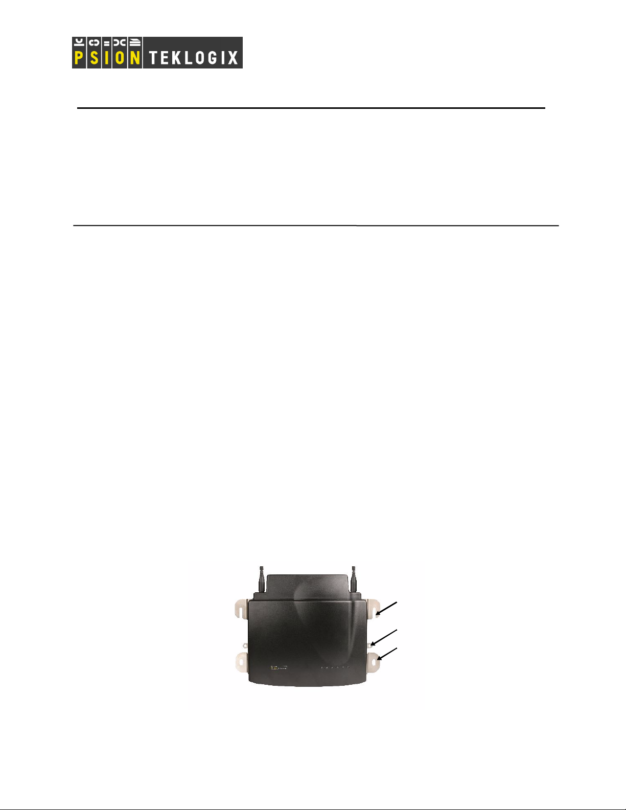
The 9160 should be situated away from the path of vehicles and free from water or dust spray. The 9160
should only be mounted in the upright position, as shown in Figure 1 below. This orientation minimizes
the risk of water entering the 9160, should the unit accidentally be sprayed.
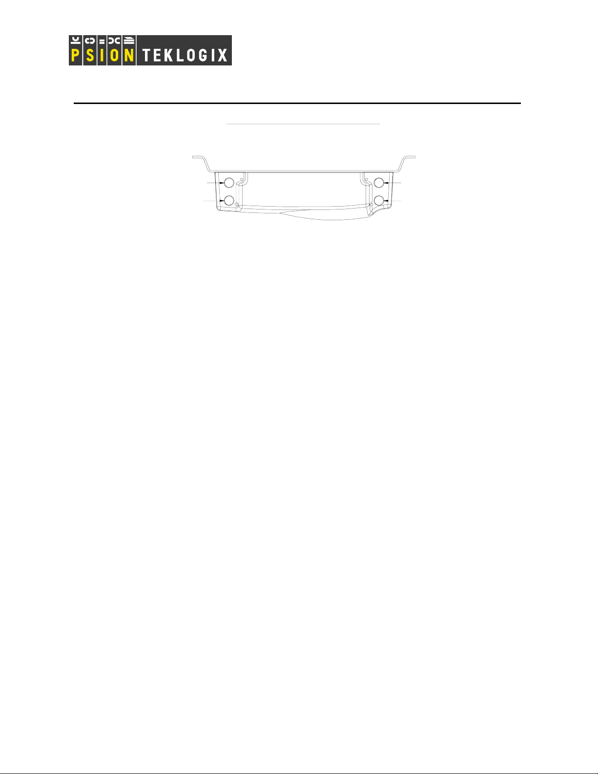
The 9160 is attached to a vertical surface using four fasteners on the rear plate (type of fasteners are
dependent on mounting surface). The top two holes in the rear plate are slots, allowing the unit to be hung
in position before the remaining bolts are installed. The bolts used for installation are SAE 1/4-20.
Mounting Slot
Cable Tie Mount
Mounting Hole
Figure 1: 9160 Installation Position
Page 1 of 8
Page 2

TECHNICAL ACQUAINT # 124a
Maintenance
The 9160 has no internal option switches and does not require physical access; all configuration settings
are done remotely (see “Navigating to Basic Settings” in the 9160 Wireless Gateway User Manual).
Environmental and radio communication considerations do still apply.
Radios
Mini-PCI 802.11g radio without integrated antenna (standard).
Mini-PCI 802.11a/g radio without integrated antenna (optional second radio).
Power And Antenna Cables
Power
To prevent accidental disconnection and stress on the 9160, antenna and power cables should be secured
within 30 cm of the unit. Secure the cables with ties to the cable tie mounts on the 9160 (see Figure 1
above). A single phase power outlet (range 100 to 240 VAC rated 1.0A minimum) should be installed
within one metre (3.1 feet) of the 9160. The 9160 automatically adjusts to input within that power range.
The power cable is removable and is available in the power type specific to your location. The 9160 AC
power supply has a universal input via a standard IEC320 connector.
To eliminate the need for AC wiring, the 9160 Wireless Gateway is compliant with IEEE 802.3af and can
be powered over its Ethernet connection. For detailed information, see “Power Over Ethernet
Requirements” in the 9160 Wireless Gateway User Manual.
WARNING: To avoid electric shock, the power cord protective grounding conductor must always be
connected to ground.
Antennas
The type of antenna required for each installation depends on the coverage requirements and the
frequencies used. For more detailed information on the Psion Teklogix antennas available for use, please
refer to TA071. Generally, a site survey determines the appropriate antenna.
The 9160 has four reverse-thread SMA jacks on top. The two front connectors can connect to RA2060
(802.11g), and the two rear SMAs can connect to RA2050 (a/g). See Figure 2.
Page 2 of 8
Page 3
TECHNICAL ACQUAINT # 124a
9160 with 2x SS RAD - TOP VIEW
Radio 2: Optional 2050 Div Ant
Radio 1: Optional 2060 Div Ant
NOTE: Tighten SMA connector to 8 lb/in (0.9 N/m).
4
3
Radio 2: 2050 Main Ant (a/g)
2
Radio 1: 2060 Main Ant (g)
1
Figure 2: 9160 Top View
The RA2050 and RA2060 radios support transmit and receive antenna diversity. With transmit diversity
the radio decides if it wants to transmit on the main or diversity antenna port. Transmit diversity switching
is much slower than diversity switching, typical dwell time is in the order of seconds. Diversity switching
is done on each packet received.
Normally the same antenna is used for both the main and diversity port. There is a special case where
different antennas are used, such as setting up a WDS link in Europe where the EIRP puts a limit on the
gain of the main antenna. Please refer to TA# 065 for more information.
A dual band ‘screw-on’ articulated blade antenna is available for small areas. A maximum of two screwon antennas is allowed, and they can be used with either Radio 1 or Radio 2. In other words, you can
install the screw-on antennas on SMA jacks 1 and 3 (for Radio 1), or 2 and 4 (for Radio 2) ONLY. Never
install them in any other combination, doing so will cause interference between the radios (even if one
operates in the 2.4 GHz and the other in the 5 GHz band.)
WARNING: Never operate the 9160 without a suitable antenna or a dummy load.
IMPORTANT!
1. FCC Requirement
To meet FCC regulatory approval, the max RF power in the 9160 must be set according to the
type of antenna used. As professional installers, Psion Teklogix personnel must abide by this rule
or risk legal action brought against the company.
To set the maximum RF output from the radio follow these steps:
• telnet to the 9160.
• Enter “max_tx wlan0 xx” to set maximum transmit power to xx% of Radio 1’s default
value. Similarly, “max_tx wlan1 xx” sets the maximum transmit power for Radio 2 (a/g).
Example: if max_tx is set to 60% and "Transmit power" on the web UI is set to 50%, the
total power transmitted is 30%, (0.6 x 0.5 = 0.3). See Table 1 for values.
Tip: determine the radio type (RA2050 or RA2060), then determine if operating in a
country that follows FC or ET regulations, and finally, read the % value for the antenna
in use.
Page 3 of 8
Page 4

TECHNICAL ACQUAINT # 124a
2. 9160 Software Power Setting vs. Antenna (per FCC Requirement)
NOTE: The FCC imposes a limit on maximum transmit power based on antenna gain, not effective
radiated power at the antenna. Therefore power settings for FCC application do not take into
account cable loss.
Antenna
(2.4GHz only)
Omni
(1) 100%=+19dBm
Gain PTX Part # RA2060 Power Limit
Setting (%)
[1]
2dBi 30222 100%
2dBi 9001953 100%
5dBi 93977 100%
7dBi 94070 100%
8dBi 1000642 100%
12dBi 21266 100%
6dBi 9002812 25% Patch
8.5dBi 9001951 16%
10dBi 9000047 25% Yagi
14dBi 21268 10%
Table 1: RA2060 Power Limit Setting
Frequency Antenna Gain PTX Part # RA2050 Power Limit
Setting (%)
[2]
2.4-2.5GHz 2dBi 30222 100%
2.4-2.5GHz 2dBi 9001953 * 100%
2.4-2.5GHz 5dBi 93977 100%
2.4-2.5GHz 7dBi 94070 100%
2.4-2.5GHz 8dBi 1000642 50%
2.4-2.5GHz
2.4-2.5GHz 6dBi 9002812 40%
2.4-2.5GHz
2.4-2.5GHz 10dBi 9000047 40%
2.4-2.5GHz
5.15-5.35GHz 4dBi 9001953 * 100%
5.15-5.35GHz 6dBi 9002008 40%
5.25-5.35GHz 10dBi 9002009 100%
5.725-5.825GHz
5.25-5.35GHz 10dBi 9001952 100%
5.725-5.825GHz
5.725-5.825GHz Dish 28dBi 9002006 20%
(2) 100%=+19dBm
Omni
12dBi 21266 20%
Patch
8.5dBi 9001951 20%
Yagi
14dBi 21268 16%
Omni
12dBi 9001950 100%
Patch
18dBi 9002007 100%
Table 2: RA2050 Power Limit Setting
Page 4 of 8
Page 5

TECHNICAL ACQUAINT # 124a
3. ETSI Requirement
TBD
Connection To Outdoor Antenna
The antenna must be installed by a qualified service person and installed according to local electrical
installation codes. The antenna should be located such that it is always at least 15 ft (4.6 m) high and 10 ft
(3 m) from the user and other people working in the area.
For a 9160 connecting to an outdoor antenna, all the following notes are applicable:
1. The shield of the outdoor antenna coaxial cable is to be connected to earth (independent of the
9160) in the building installation, provided the installation is acceptable to the authorities in
the country of usage.
2. A supplementary equipment earthing conductor is to be installed between the 9160 and
earth—that is, in addition to the equipment earthing conductor in the power supply cord.
3. The supplementary equipment earthing conductor may not be smaller in size than the
unearthed branch-circuit supply conductors (min 0.75 sq. mm nominal cross-sectional area or
18AWG). The supplementary equipment earthing conductor is to be connected to the 9160 at
the terminal provided, and connected to earth in a manner that will retain the earth connection
when the power supply cord is unplugged. The connection to earth of the supplementary
earthing conductor shall be in compliance with the appropriate rules for terminating bonding
jumpers in the country of usage. Termination of the supplementary equipment earthing
conductor is permitted to be made to building steel, to a metal electrical raceway system, or to
any earthed item that is permanently and reliably connected to the electrical service equipment
earthed.
4. Bare, covered, or insulated earthing conductors are acceptable. A covered or insulated
earthing conductor shall have a continuous outer finish that is either green (Canada and USA
only), or green-and-yellow (all countries).
5. Avoid servicing during an electrical storm. There may be a remote risk of electrical shock
from lightning.
6. For Finland, Norway, and Sweden, the equipment is to be used in a RESTRICTED ACCESS
LOCATION where equipotential bonding has been applied. The permanently connected
PROTECTIVE EARTHING CONDUCTOR is to be installed by a SERVICE PERSON.
WARNING: For RF safety considerations, users are not allowed to approach close to the antenna.
Page 5 of 8
Page 6

TECHNICAL ACQUAINT # 124a
Psion Teklogix supplies the coaxial cable required to connect the 9160 to the antenna. When determining
the location of the antenna, the coverage requirements of the antenna are considered in conjunction with
the environmental requirements of the 9160. The coaxial cable must be routed and secured using wire
anchors and/or coaxial nail clips. A few extra inches of cable are required near the antenna and the 9160 to
make disconnection easier.
Connecting To External Devices
This section contains general guidelines for connecting the 9160 to external devices such as network
controllers, base stations, host computers, PCs, and video display terminals.
Ports
Figure 3 shows the locations of the port and power connectors on the base of the 9160. The port pinouts
are described in “Appendix B: Port Pinouts and Cable Diagrams” in the 9160 Wireless Gateway User
Manual.
LED: 1 4 5 632Operating Status
AC Power Socket
RS-232 Console Port
10BaseT/100BaseT Ethernet Adaptor
Figure 3: 9160 Port And LED Locations
LAN Installation: Overview
Because the 9160 provides Ethernet connectivity, it can be added to an existing LAN. Generally, LAN
installations are handled with the help of the network administrators, as they are familiar with their
network and its configuration.
Once the 9160 is installed, connected and powered on, the system administrator can access the unit to
check the configuration and to assign the 9160 its unique IP address. This may be done through the
network (see “ Changing The Configuration With A Web Browser” on page 7). Subsequent changes in
the network, such as the addition of stations or users, would also require that the 9160 configuration be
changed.
Page 6 of 8
Page 7

r
TECHNICAL ACQUAINT # 124a
IMPORTANT: Once the 9160 is configured and rebooted the first time, the DHCP should be
disabled—unless the 9160 obtains its IP address from a server.
LAN Installation: Ethernet
The 9160 is a high-performance controller that supports 100Mb/s Fast Ethernet LANs, as well as 10Mb/s,
with both full and half duplex operation. It comes equipped with a 10BaseT/100BaseT card (using a
category-5 twisted pair cable, an RJ-45 connector, running at a rate of 10 or 100Mb/s).
NOTE: The 9160 does not support any connection type other than Ethernet 10BaseT and 100BaseT.
For a description of port pinouts, refer to “Appendix B: Port Pinouts and Cable Diagrams” in the 9160
Wireless Gateway User Manual.
Ethernet Cabling
The maximum cable segment length allowed between repeaters for the 9160 (10BaseT/100BaseT Ethernet
cabling) is 100 m.
Status Indicators (LEDs)
The high-performance 9160 has six status indicators on the front of the enclosure, as shown in Figure 3.
numbered and coloured LEDs on the front of the unit indicate the operating status for each port, as
The
described in Table 3.
LED
Numbe
1 Ethernet link Link indicator for 10BaseT/100BaseT:
2 Ethernet activity Ethernet LAN activity (Rx/Tx) green
3 Radio 1 status Radio 1 activity (Rx/Tx) green
4 Radio 2 status Radio 2 activity (Rx/Tx) green
5 Not used Always off (unused) green
6 Power LED On solid = Unit powered
*
LED 1 colour shows orientation of LEDs when viewed from a distance.
Name Function Colour
yellow*
ON = good link; OFF = no link
green
LED Off = No power to unit
Table 3: 9160 LED Functions: Front Enclosure
Connecting A Video Display Terminal
An ANSI compatible video display terminal (e.g., DEC VT220 or higher), or a PC running terminal
emulation, is used for diagnostic purposes.
Page 7 of 8
Page 8

TECHNICAL ACQUAINT # 124a
The terminal is connected to the RS-232 port on the 9160 (see Figure 3). This port is normally set to
operate at 19,200 baud, 8 bits, 1 stop bit, no parity. To comply with Part 15 of the FCC rules for a Class B
computing device, only the cable supplied (Part no. 19387) should be used.
Changing The Configuration With A Web Browser
The 9160 Flash memory can be reconfigured remotely via the network using a standard HTML Web
Browser such as MS Internet Explorer (version 4.0 or later) or Firefox. See “Chapter 4: Quick Steps for
Setup and Launch” in the 9160 Wireless Gateway User Manual for instructions on changing the
parameters and general configuration settings.
Page 8 of 8
 Loading...