

Chapter 5: Configuration
Setting this parameter to on allows t h e i mager to make automatic gain, int egr ation
and illumination adjust ments base d on ambi ent li ght before capturing the bar code.
If the adjustment is insufficient, further adjustments are made automatically before
another image is captured.
Fast Converge
Note: “Auto Exposure” must be set to ‘on’ in order for this parameter
to function.
Keep in mind that while this parame ter can impr o ve imager performance,
“Fast Converge” increases battery power consumption.
Setting this parameter to on speeds t he “ Aut o Expos ure ” pro cess . It all ows t he
imager to rapidly snap a number of bar code capture attempts while finding idea l
values for gain, integrat ion a nd il lumi nati on.
Max Gain, Max Integration And Max Illumination
Important: These parameter values should only be changed by qualified Psion
Teklogix personnel.
Imager
These parameters represent i nt erna l val ues used by the 2D imager. The “Auto
Exposure” parameter automatic ally adjus ts the “Ma x Gain”, “Max Integr ation” and
“Max Illumination” parameters to prod uce the best bar code read. Keep in mind that
“Auto Exposure” must be set to on i n orde r f or t hese parameter values to be
automatically adjuste d.
Double-tapping on any of these pa ramet er s displays an associated dialog box i n
which an allowable range is dis pla yed: Max Gain – 3 57 to 7920, Max Integration –
0 to 65535, Max Illumination – 0 to 7.
Decoder Timeout
The decoder is a set of al gorithms that exa mine the image and attempt to f ind the bar
codes, and then turn the pixels into data that the computer ca n use—thi s pr ocess
takes time. “Decoder Timeout” limits the amount o f t ime th e dec oder will spend
attempting to decode an imag e, and f orc es i t t o st op and grab a new image, which
will probably be easier to d ecode .
Note: When decoding multiple bar codes in one image, the value assigned to
‘Decoder Timeout’ sho uld be increa sed to 200ms/extra ba r c ode after the
WORKABOUT PRO G2 Hand-Held With Windows Embedded CE 5.0 User Manual 193

Chapter 5: Configuration
Imager
first.
Adaptive Windowing
“Adaptive Wi ndowi ng” i s an a dvanc ed technique used to speed up bar code
recognition in cert ain appl icati ons. This para meter aut omatical ly reduces the si ze of
the window to the user- progr amme d windo w size when i t su ccessfully decodes
(which reduces decode time the next time it is used), but incre ase s it to t he f ull si ze
window (1280x1024 for SX5303) on a failed decode.
Note: This feature assumes that you have reached an understanding about how
the device operates in y our application, and that, afte r a le arni ng pe ri od,
operators will get used to using the imager in one particular way. It also
assumes that a trained operator will usually only have near miss scenarios.
Constant Illumination
“Constant Illumination” is used to reduce the intrusivene ss of the device’s
illumination on the observer. Ins te ad of the i ll umina tion turning on and off ev ery
time the device attempts a dec ode ( 2-4 t imes per s econ d), t he illumination stays on
from the time the trigger is pull ed until a decode is succe ssful. Thi s featur e is usef ul
in low light environments , since it will also reduce the dis traction that the
illumination can have on nearb y co- wo rkers.
5.11.5.3 Code 39 Settings
Enabled
Set this parameter to on to enable “Code 39”.
Field Size/Char
Refer to page 143 for details.
5.11.5.4 Code 128 Settings
Enabled
Set this parameter to on to enable “Code 128”.
Field Size/Char
Refer to page 143 for details.
194 WORKABOUT PRO G2 Hand-Held With Windows Embedded CE 5.0 User Manual

Chapter 5: Configuration
5.11.5.5 EAN 13
Enabled
Set this parameter to on to enable “EAN 13”.
Addendum
An addendum is a separate bar code, s uppl ementary to the main bar code.
This parameter provides thre e opt ions : Di sabl ed, Opt iona l and Required.
Depending on the value chosen for this parameter, an a ddendum i s re cogni zed
or ignored.
• Double-tap on Addendum to display a d ial og box listing your options.
• Highlight an item, and t ap on OK.
When “Addendum” is set to
addendum. If this parameter is s et to
an addendum and if one exists, appen ds it to the main bar code. When the
parameter is set to
without an addendum.
Note: Setting “Addendum” to ‘Optional’ reduces performance. It should only
be chosen if at least some of the bar codes being read have addendums.
Required, the scanner does not accept the ma in ba r code
Disabled, the scanner does not rec ogniz e an
Optional, the scanner searches for
Imager
Prefix/Suffix
Refer to “Prefix/Suffi x” beginning on page 144.
5.11.5.6 EAN 8
Enabled
Set this parameter to on to enable “EAN 8”.
Addendum
Refer to “Addendum” on page 195.
Prefix/Suffix
Refer to “Prefix/Suffi x” beginning on page 144.
WORKABOUT PRO G2 Hand-Held With Windows Embedded CE 5.0 User Manual 195

Chapter 5: Configuration
Imager
5.11.5.7 UPC A
Enabled
Set this parameter to on to enable “UPC A”.
Addendum
Refer to “Addendum” on page 195.
Prefix/Suffix
Refer to “Prefix/Suffi x” beginning on page 144.
5.11.5.8 UPC E
Enabled
Set this parameter to on to enable “UPC E”.
Addendum
Refer to “Addendum” on page 195.
Prefix/Suffix
Refer to “Prefix/Suffi x” beginning on page 144.
5.11.5.9 Code 93
Enabled
Set this parameter to on to enable “Code 93”.
Field Size/Char
Refer to page 143 for details.
5.11.5.10 Codabar
Enabled
Set this parameter to on to enable “Codabar”.
Field Size/Char
Refer to page 143 for details.
196 WORKABOUT PRO G2 Hand-Held With Windows Embedded CE 5.0 User Manual

Chapter 5: Configuration
5.11.5.11 Interleaved 2 of 5
Enabled
Set this parameter to on to enable “Interleaved 2 of 5” .
Field Size/Char
Refer to page 143 for details.
5.11.5.12 RSS Code (Reduced Space Symbology)
Enable
Setting this parameter to on enables “RSS Code” scanning capability.
Field Size/Char
Refer to page 143 for details.
5.11.5.13 Composite
Important: To successfully re ad thi s t ype o f bar code, the two types of symbolo-
gies included in a composite bar c ode must be enabled.
Imager
Enabled
Set this parameter to on to enable “Composite” bar codes.
5.11.5.14 PDF-417
Enable
Setting this parameter to on enables PDF-417 two dimensional (2D) coding.
Field Size/Char
Refer to page 143 for details.
WORKABOUT PRO G2 Hand-Held With Windows Embedded CE 5.0 User Manual 197

Chapter 5: Configuration
Imager
5.11.5.15 Micro PDF-417
Enable
Setting this parameter to on enables “Micr o PDF-417 ” bar code scanning. Micro
PDF-417 is a multi-row symbology t hat is useful for applications requir ing g rea ter
area efficiency but lower data capacity than PDF-417.
Field Size/Char
Refer to page 143 for details.
5.11.5.16 2D Data Matrix
Enable
Set this parameter to on to enable “Data Matrix”.
Field Size/Char
Refer to page 143 for details.
5.11.5.17 2D QR Code
Enabled
Set this parameter to on to enable “2D QR Code”.
Field Size/Char
Refer to page 143 for details.
5.11.5.18 2D Maxicode
Enabled
Set this parameter to on to enable “2D Maxicode”.
Field Size/Char
Refer to page 143 for details.
5.11.5.19 2D Aztec
Enabled
Set this parameter to on to enable “Aztec”.
198 WORKABOUT PRO G2 Hand-Held With Windows Embedded CE 5.0 User Manual

Field Size/Char
Refer to page 143 for details.
5.11.5.20 Postal: PlaNET
Enabled
Set this parameter to on to enable “Postal: PlaNET”.
Field Size/Char
Refer to page 143 for details.
5.11.5.21 Postal: PostNET
Enabled
Set this parameter to on to enable “Postal: PostNET”.
Field Size/Char
Refer to page 143 for details.
Chapter 5: Configuration
Imager
5.11.5.22 Postal: Australian
Enabled
Set this parameter to on to enable “Postal: Australian”.
Field Size/Char
Refer to page 143 for details.
5.11.5.23 Postal: Japanese
Enabled
Set this parameter to on to enable “Postal: Japanese”.
Field Size/Char
Refer to page 143 for details.
WORKABOUT PRO G2 Hand-Held With Windows Embedded CE 5.0 User Manual 199
Chapter 5: Configuration
Options
5.11.5.24 Postal: Korean
Enabled
Set this parameter to on to enable “Postal: Korean”.
Field Size/Char
Refer to page 143 for details.
5.11.5.25 Postal: Royal
Enabled
Set this parameter to on to enable “Postal: Royal”.
Field Size/Char
Refer to page 143 for details.
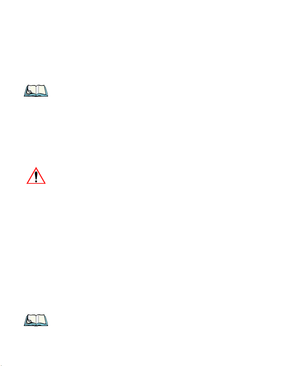
5.11.6 Options
This tab allows you to tailor the doubl e-c li ck par amet ers and t he di spl ay opt ions
associated with your scanner.
200 WORKABOUT PRO G2 Hand-Held With Windows Embedded CE 5.0 User Manual

Chapter 5: Configuration
Options
5.11.6.1 Double Click Parameters
Click Time (msec)
This parameter controls the max imum gap time (in milli seconds) for a double-click.
If the time between the firs t and second clicks of the scann er t ri gger is within this
time, it is considered a double-c lick. The allowable range is 0 to 1000. A value o f
zero disables this feat ure.
A double-click produces different results depending on whe the r or not a value is
assigned in the “Click Data” para meter. When a value is not assig ned for the “Cl ick
Data”, double-clicking the scanner trigger override s t he ta rget dot delay set in t he
“Dot Time” par amete r and initiates a normal scan sweep. If a v alue is a ssi gned for
the “Click Data” parameter, double-c li ckin g the scanner trigger inserts t he “Cl ick
Data” value rather than ini ti ati ng a s can.
Click Data
For both integrated and exter nal sca nner s, th is parameter determines which
character is sent to the application installe d in y our hand-held following a
double-click. A dial og box appe ars, askin g that you press t he key you want to i nsert.
The ASCII/Unicode key value of t he ke ypre ss is displayed.
5.11.6.2 Display Parameters
Scan Result
When this parameter is enabled, t he t ype of bar code and the result of the scan
appear on the screen. Note t hat thi s information is only displaye d af ter a su ccessful
decode and is visible only whil e t he scanner trigger is pressed. Wh en th e tr igger is
released, this infor mati on is cleared from the screen.
Scan Indicator
When this parameter is enabled, t he l aser warning logo appears on the displ ay
whenever the scanner is ac ti vat ed.
Scan Result Time (sec)
The value assigned to the “Scan Resul t Time (sec)” parameter det ermines ho w long
the scan results of a successful sca n are displayed on the screen. T ime is measured in
seconds, and a value of “0” (zer o) di sables the parameter. When you choose this
option, a dialog box appears wher e you can enter a value.
WORKABOUT PRO G2 Hand-Held With Windows Embedded CE 5.0 User Manual 201

Chapter 5: Configuration
Options
Note: To remove the scan result from the screen before the “Result Time” has
expired, point the scanner away from the bar code and press the trigger.
Good Scan Beep And Bad Scan Beep
These parameters determine whet her or not the hand-held emits an a udib le s canne r
‘beep’ when a good (successful) sca n or a bad (unsucce ssful) scan is performed. Set
these parameters to either on t o enable the beeper or off to disa ble it .
Soft Scan Timeout
This parameter is used by the SDK “Sca n” f unct ion ( sof t- scan: st art ing a sc an
session via the SDK function, ins tea d of a phys ical user trigger press). The value
assigned to this parameter dete rmine s the soft-scan timeout from 1 to 10 se c.
(default is 3 sec. ).
Scan Log File
If this parameter is enabled, the inp ut barcode a nd the modified/ translated output bar
code are logged in the file \Flash Disk\ScanLog.txt. Keep in mind that i f t he “Sc an
Log File” is enabled, ther e i s a sl ight performance effect when performing multiple
scans since the log fi le i s written to persistent st ora ge.
202 WORKABOUT PRO G2 Hand-Held With Windows Embedded CE 5.0 User Manual
Chapter 5: Configuration
Translations Tab
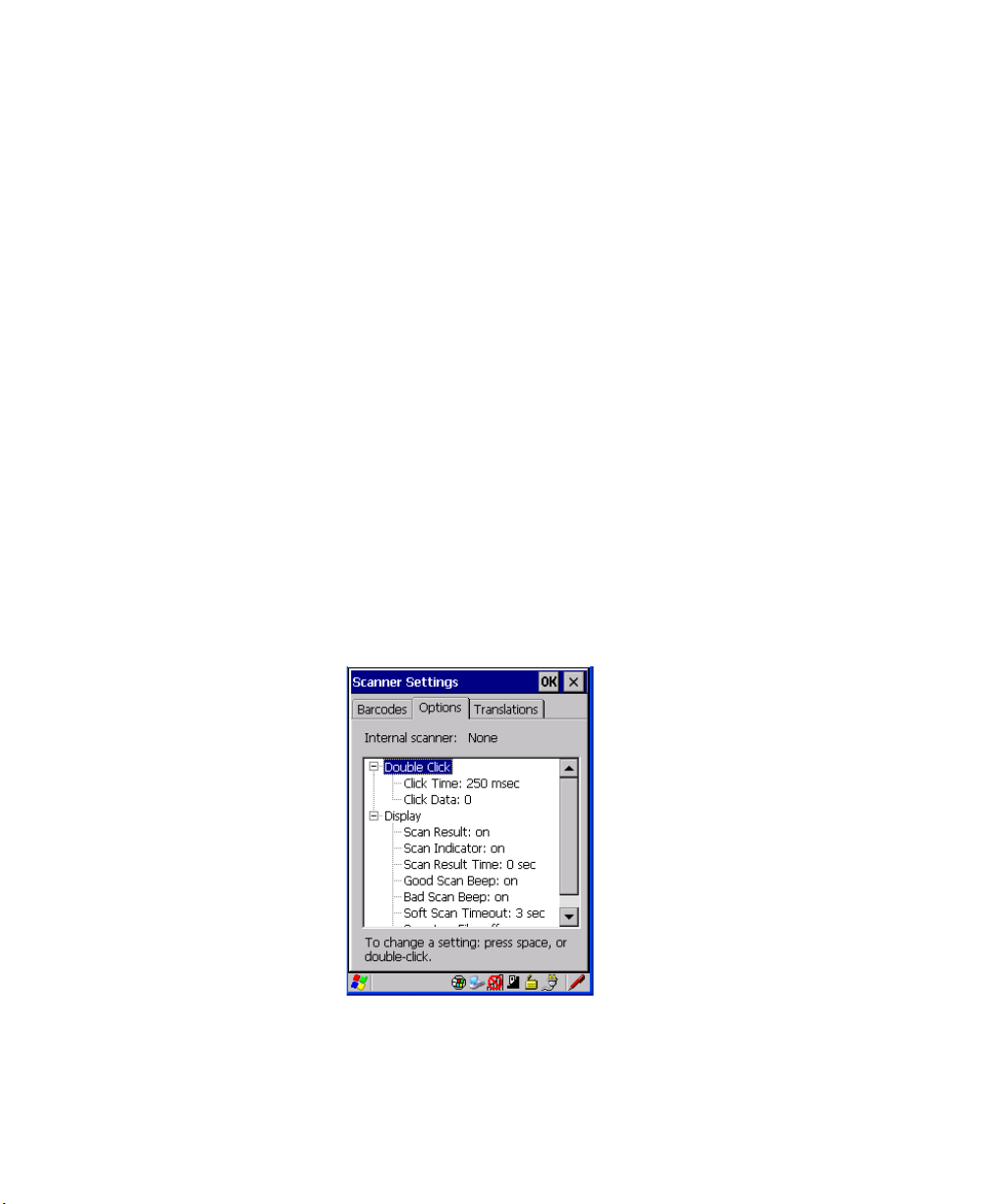
5.11.7 Translations Tab
The Translations tab allows you to define up to 10 cases, each consisting of up to 10
rules in sequential order . Onl y one case will be a ppli ed to a bar code a nd a case will
only be applied if all rules specified in the case are succe ssful – if a rule within a
case fails, the entire ca se fails.
•In the Translation tab, tap on the Cas e # to create rules.
WORKABOUT PRO G2 Hand-Held With Windows Embedded CE 5.0 User Manual 203
Chapter 5: Configuration
Translations Tab
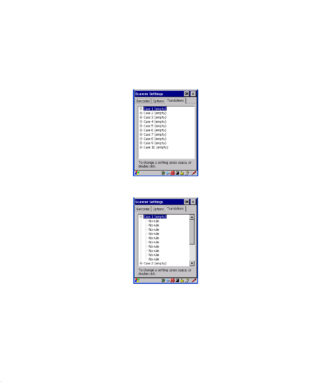
• Tap on the No rule dropdown menu to display the rules.
When you choose a rule, an associat ed screen is displayed in which you can d efi ne
the rule.
204 WORKABOUT PRO G2 Hand-Held With Windows Embedded CE 5.0 User Manual

Chapter 5: Configuration
SNMP (Simple Network Management Protocol) Setup
5.11.7.1 Case Rules
The case rules are defined as fol lows :
• No rule – ignored.
• Search and repla ce – r epl ace s all instances of the match stri ng. (Note that
this rule cannot fail.)
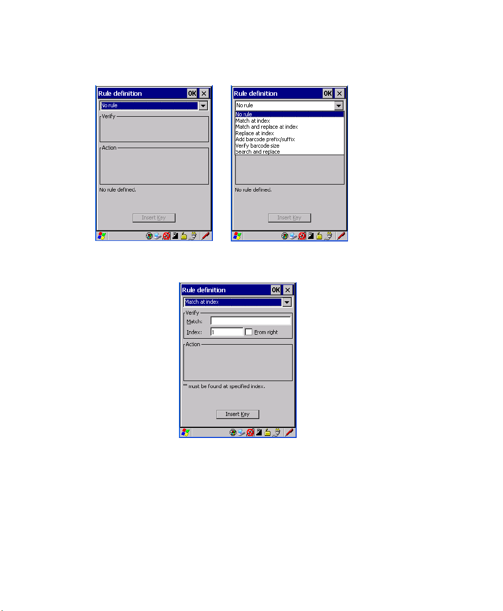
• Match at index – matc hes t he mat ch st ri ng at a specified index.
• Match and replace at i ndex – matches the match strin g at a spe cif ied index
and replaces/changes i t.
• Replace at index – replaces/changes unspecified data in a given range.
• Add barcode prefix /s uffix – adds a global prefix or suffix.
• Verify barcode size – verifie s the bar code s ize . This rule should generally
be assigned first, bef ore crea ting subsequent rules.
Note: Keep in mind that the effects of previously applied rules must be taken
into account when cr eating subs equent rules. For example, if the bar code
size is important, it should be check ed before any rules that might change
the size are applied.
Translat ion i nf ormat ion a bout t h e s tat us of eac h cas e/rule is displayed in the s can
log file (see “Scan Log File” on pag e 202) when enabled. This is useful if a case
fails, and you are trying to dete rmine why a rule is failing.
5.12 SNMP (Simple Network Management Protocol)
Setup
Simple Network Management Protocol (SNMP) is t he protocol used t o monitor and
manage devices attached to a TCP/I P net w ork ( prov idi ng the y support SNMP).
SNMP uses Management Information Bases (MIBs) that def ine the vari abl es an
SNMP Network Management Station c an ac ces s. Each product has a defined set of
MIBs that determine how SNMP operates, the type of access allowed and so on.
All Psion Teklogix products support the TEKLOGIX-GENERIC-MIB—a MIB that
defines some common features across Psion Teklogix products.
WORKABOUT PRO G2 Hand-Held With Windows Embedded CE 5.0 User Manual 205
Chapter 5: Configuration
Contact Tab
All devices also support MIB-II , a management information base that def ines the
common features of TCP/IP ne tworks. The SNMP Agent s oftware embedded i n the
WORKABOUT PRO G2 product supports SNMPv1 (RFC 1157).
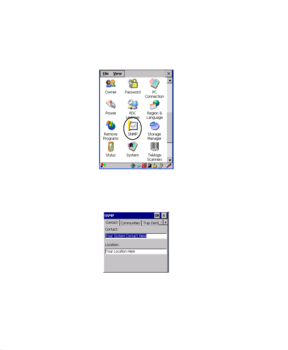
•In the Control Panel, choose th e SNMP
icon.
Figure 5.20 SNMP Icon
5.12.1 Contact Tab
The SNMP dialog box is displayed.
Contact
This field identifies t he co ntact person for this managed node alo ng wit h
information about how to get in t ouch with this person. The content of t his
parameter is accessible t hrou gh MI B-I I’s sysContact object.
206 WORKABOUT PRO G2 Hand-Held With Windows Embedded CE 5.0 User Manual
Chapter 5: Configuration
Communities Tab
Location
This parameter is used to identify the physical locati on of this node ( e.g., Warehouse
A: Pillar 32B). The content of t his parameter is accessible thr ough MIB-I I’s
sysLocation object.
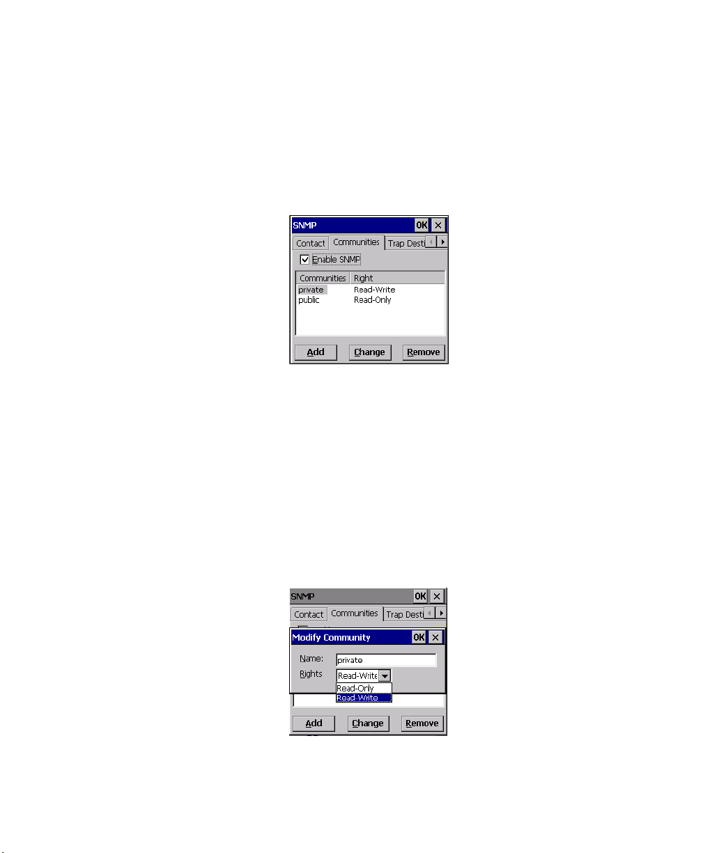
5.12.2 Communities Tab
The Communities t ab allows you to limit a ccess to SNMP-managed devices to those
SNMP Managers with matching “community names”, as speci fi ed by RFC 1157.
Enable SNMP
Enabling Enable SNMP allows the dev ice to respond to SNMP queries and to send
Traps. Afte r ena bling this option and rebooting the device, the SNMP Agent will
automatically start up. To disable this feature, remove t he ch eck mar k fr om the
check box.
5.12.2.1 Adding A Community
• Choose the Add button to add a new ‘community’.
WORKABOUT PRO G2 Hand-Held With Windows Embedded CE 5.0 User Manual 207

Chapter 5: Configuration
Communities Tab
Name
The value assigned here is th e name assigned by the networ k administrator t o the set
of devices to which this managed n ode belongs.
Rights
This menu allows you to specify acc ess , tha t is , ‘Read-Only’ or ‘Read-W r it e’
5.12.2.2 Modifying A Community Setting
To modify an existing communit y:
• Highlight the communi ty y ou want to alter .
• Choose the Change
button.
A Modify Community dialog box is displayed, listing the community y ou
highlighted.
•Edit the Name and/or Rights, and press [ENTER] to save your changes.
5.12.2.3 Removing An Existing Community
To remove an item:
• Highlight the community you want to remove in the Communities tab and
then choose the Remove button.
A Delete Confirmation screen is displayed.
• To remove a community, choose t he Yes button, or
If you decide not to remove the c ommunity, choose the No button.
208 WORKABOUT PRO G2 Hand-Held With Windows Embedded CE 5.0 User Manual
Chapter 5: Configuration
Trap Destination Tab
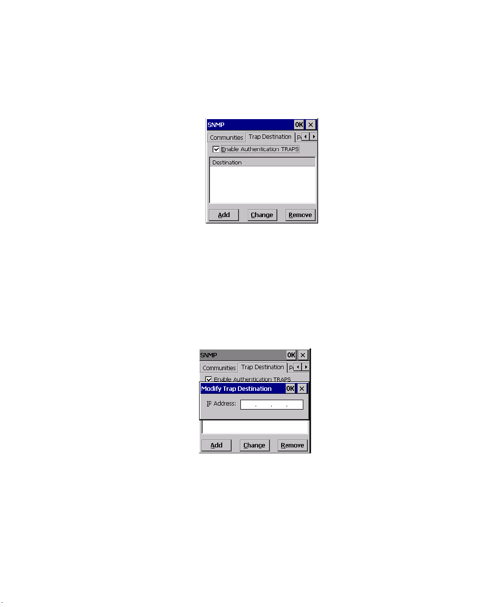
5.12.3 Trap Destination Tab
A trap is an unsolici ted repor t sent to SNMP Manage rs by the SNMP Agent ru nning
on the managed node. This option allows you to define where the report will be sent.
5.12.3.1 Enabling Authentication TRAPS
Enabling Enable Authentication TRAPS allows authorization traps to be sent when
a failure is detected ( e.g., an SNMP message receiv ed with a b ad communi ty name).
5.12.3.2 Adding A Destination
To add a new destination:
• Choose the Add button.
• Type a destination IP address in the text box provi ded, a nd press [ENTER].
5.12.3.3 Changing A Destination
To change an existing trap destination:
• Highlight the destin ation yo u want to alt er in the
then choose the Change button.
WORKABOUT PRO G2 Hand-Held With Windows Embedded CE 5.0 User Manual 209
Trap Destination tab, and
Chapter 5: Configuration
Permitted Hosts Tab
A dialog box like the one displa yed when you add a destination is displayed.
• Make the changes to the destination, and press [ENTER] to save the
changes.
5.12.3.4 Removing A Trap Destination
To remove a trap destination:
•In the Trap Destination tab, highlight the desti nati on you wa nt t o del et e.
• Choose the Remove butto n.
A Delete Confirmation screen is displayed.
• To remove a destination, choose the Yes button, or
If you decide not to remove the de st inat ion , choos e th e No button.
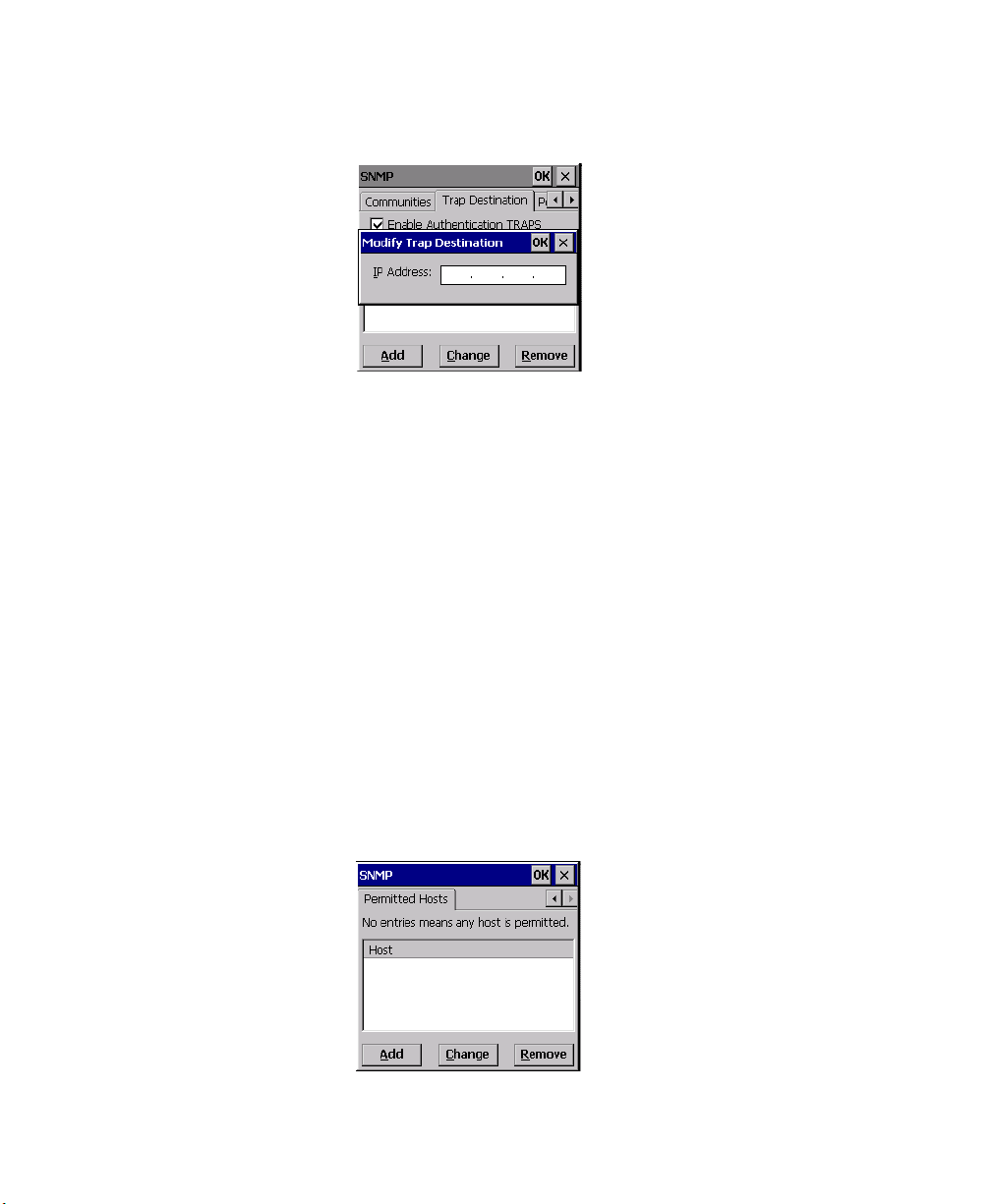
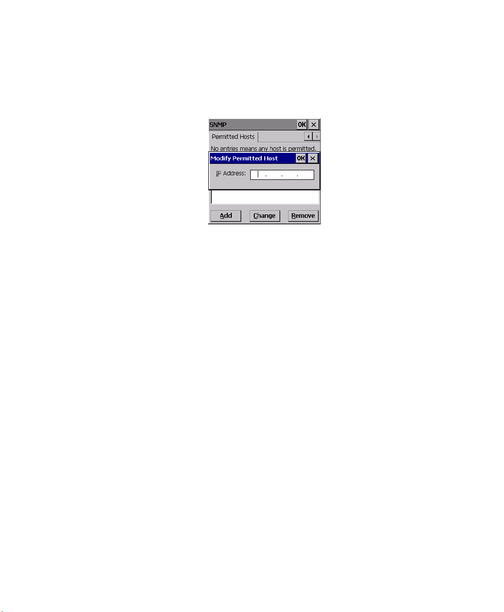
5.12.4 Permitted Hosts Tab
For security reasons, the Net work Admini st rat or may want to restrict SNMP-node
access to a known sub-set of SNMP Manag ers . This tab l is ts t he I P addr ess es of al l
the SNMP Managers which are allowed t o monit or a nd manage thi s device. If no
entries are liste d, the devi ce wil l a ccept SNMP queries from any host.
210 WORKABOUT PRO G2 Hand-Held With Windows Embedded CE 5.0 User Manual
Chapter 5: Configuration
Permitted Hosts Tab
5.12.4.1 Adding A Host
To add a new host:
• Highlight the Add button, and press [ENTER].
• Type a new host IP address in the text box provided, and pre ss [ ENTER].
5.12.4.2 Changing A Host
To change an existing host IP address:
• Highlight the IP addr ess you want to alter in the Permitted Hosts tab, and
then choose the Change button.
A dialog box like the one displa yed whe n you add a host is displayed.
• Make the necessary changes, and press [ENTER].
WORKABOUT PRO G2 Hand-Held With Windows Embedded CE 5.0 User Manual 211


PERIPHERAL DEVICES & ACCESSORIES 6
6.1 Carrying Accessories.............................215
6.1.1 Attaching The Hand Strap.......................215
6.1.2 Attaching The Pistol Grip.............. ...... ...217
6.1.3 Protective Carrying Case........................218
6.1.3.1 Using The Swivel Belt Loop With The Carrying Case.....218
6.1.4 Soft Shell Holster...........................220
6.2 The Batteries .................................221
6.3 Chargers And Docking Stations.......................221
6.3.1 Installation–Chargers And Docking Stations.............221
6.3.2 Power Consumption Considerations......... ...... ...221
6.3.3 Operator Controls...........................222
6.3.4 Important Charger Safety Instructions.................222
6.4 Desktop Docking Station...........................223
6.4.1 Charging A Battery Ins tal led In The WORKABOUT PRO G2. . . . 224
6.4.2 Charging A Spare Battery.............. ...... ...225
6.4.3 Battery Charge Duration........................225
6.4.4 Charger LED Indicators........................225
6.4.5 Troubles hoot ing The Charging Operation Of The Dock .......225
6.4.6 Desktop Docking Station Ports ....................226
6.4.7 Linking A WORKABOUT PRO G2 To A PC............226
6.4.7.1 Using Microsoft ActiveSync To Work With Files.......227
6.4.8 Linking A WORKABOUT PRO G2 T o An Ether net Networ k. . . . 227
6.4.8.1 Network Access.........................227
6.4.9 Troubles hoot ing The Docking Station Operat io ns. . .........228
6.5 Single Battery Charger–Model #WA3001-G1 . ...............228
6.5.1 Inserting A Battery In The Single Battery Charger..........228
6.5.2 Battery Charge Duration........................228
6.5.3 Charge Indicators–The LED......................229
WORKABOUT PRO Hand-Held Computer With Windows Mobile 5.0 User Manual 213
Chapter 6: Peripheral Devices & Accessories
6.6 Quad Battery Charger–Model #WA3004-G1.................229
6.6.1 Charging Batteries...........................230
6.6.2 Battery Charge Duration........................230
6.6.3 Charge Indicators–The LEDs......................230
6.6.4 Troubles hoot ing . . . .........................230
6.6.4.1 Excessive Charge Duration..................230
6.6.4.2 Indicator Flashing Red.....................230
6.6.4.3 Power LED Does Not Light Up.... ...... ......231
6.6.4.4 Indicator Does Not Light When Battery Installed.......231
6.7 Quad Docking Station–Model # WA4004-G1.................232
6.7.1 Quad Docking Station Setup......................232
6.7.2 Quad Indicators.............................233
6.7.3 Inserting A WORKABOUT In The Quad Docking Station......233
6.7.4 Network Access . . . .........................233
6.7.4.1 Network Addressing......................233
6.7.5 Battery Charging–LED Behaviour....... ...... ......234
6.7.6 Troubles hoot ing . . . .........................234
6.7.6.1 Network Link Unsuccessful..................234
6.7.6.2 Hand-Held LED Does Not Light When Docked.......234
6.8 The Vehicle Cradle..............................235
6.8.1 Vehicle Cradle Mounting Recommendations . ............235
6.8.1.1 Mounting Template......................236
6.8.2 Wiring Guidelines ...........................236
6.8.3 Using The Vehicle Cradle .......................236
6.8.4 Maintaining The Vehicle Cradle....................236
6.8.5 Powered Cradle Installation In High Voltage Vehicles.........237
6.8.6 Powered Vehicle Cradle Installation..................237
6.8.6.1 Wiring Vehicle Power To The Cradle.............238
6.8.7 The Port Replicator............... ...... ......238
6.9 Bluetooth Peripherals.............................239
214 WORKABOUT PRO Hand-Held Computer With Windows Mobile 5.0 User Manual

Chapter 6: Peripheral Devices & Accessories
Carrying Accessories
6.1 Carrying Accessories
There are a variety of carrying accessories to help the operator work safely and
comfortably with the WORKABOUT PRO G2.
Carrying Accessory Model Number
Hand Strap
Pistol Grip WA6001-G1
Pistol Grip for SX5393 Imager WA6002-G1
Protective Vinyl Case
Soft Shell Holster WA6050
WA6025 for WORKABOUT PRO C G2
WA6125 for WORKABOUT PRO S G2
WA6091 for WORKABOUT PRO C G2
WA6190 for WORKABOUT PRO S G2
Table 6.1 Carrying Accessories
Important: Do not use adhesives such as Loctite to secure screws on
carrying accessories. These chemicals may damage the
plastic casing.
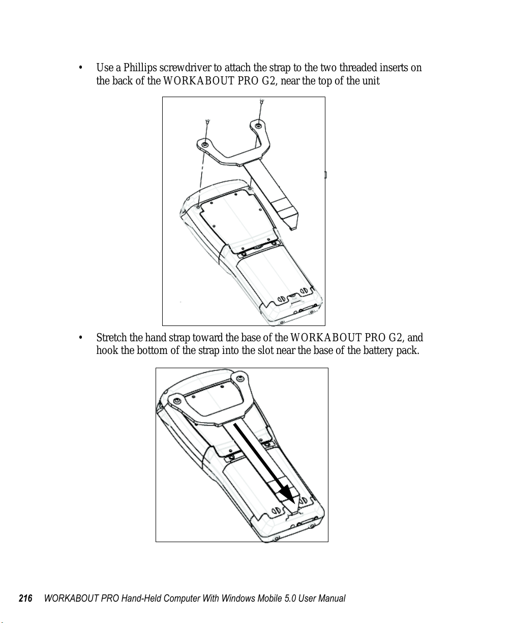
6.1.1 Attaching The Hand Strap
The hand strap can be attached to th e back of the WORKABOUT PRO G2 to
provide a secure means for oper ator s t o car ry t he ha nd-held.
The hand strap is attached t o the back of unit using two Phillips head sc rews
provided with this accessor y.
WORKABOUT PRO Hand-Held Computer With Windows Mobile 5.0 User Manual 215
Chapter 6: Peripheral Devices & Accessories
Attaching The Hand Strap
• Use a Phillips screwdriver to attach the st rap t o the two threaded inserts on
the back of the WORKABOUT PRO G2, near the top of the unit
• Stretch the hand str ap toward the base of the WORKABOUT PRO G2, and
hook the bottom of the strap int o t he sl ot near the base of the battery pac k.
216 WORKABOUT PRO Hand-Held Computer With Windows Mobile 5.0 User Manual
Chapter 6: Peripheral Devices & Accessories
Attaching The Pistol Grip
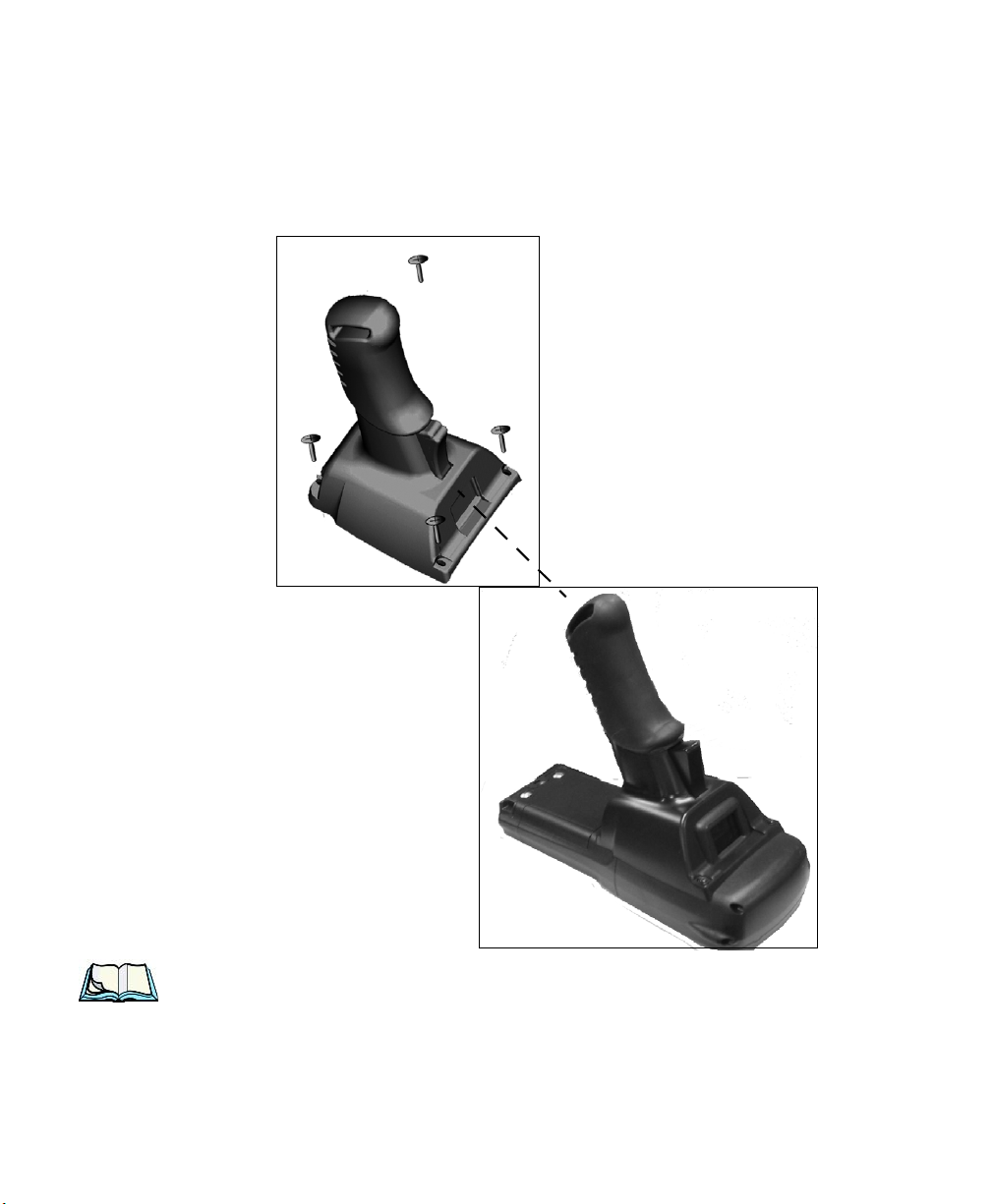
6.1.2 Attaching The Pistol Grip
The pistol grip is attache d to the f our threaded inserts on the back of the WORKABOUT PRO G2. Four Phillips head screws are provi ded with this accessory.
Note: Prior to installation, make sure the trigger mechanism is securely
snapped into the pistol grip body and that the trigger operates properly.
• Position the pis tol grip so tha t it fits snu gly over the back of the unit and the
holes in the pistol grip a re a ligned with the threaded inserts on the back of
the WORKABOUT PRO G2.
WORKABOUT PRO Hand-Held Computer With Windows Mobile 5.0 User Manual 217

Chapter 6: Peripheral Devices & Accessories
Protective Carrying Case
• Ti ghten the scr ews to a torque o f 3 lbs-in (3 kgf-cm) to secure the pi stol grip
in place.
6.1.3 Protective Carrying Case
A carrying case is available for WORKABOUT PRO G2s to shield the unit from
damage. It is equipped with a sof t pl ast ic wi ndow to protect the unit display and
keyboard. A variety of cases ar e ava il able , depe nding on the type of end-cap
attached to your unit.
6.1.3.1 Using The Swivel Belt Loop With The Carrying Case
The WORKABOUT PRO G2 carrying case is equipped with tw o ri ngs on to whi ch
you can attach a swivel belt l oop so that you c an hang the unit from your belt . If you
prefer , you can also at tach a belt c lip to this a ccessory so t hat you can clamp t he unit
onto your waistband or belt. (rather than slide your belt t hrough the belt loop).
Figure 6.1 Belt Loop And Belt Clip
• Clip the two hooks on the belt strap to the bottom of the car ryi ng cas e.
218 WORKABOUT PRO Hand-Held Computer With Windows Mobile 5.0 User Manual
Chapter 6: Peripheral Devices & Accessories
Protective Carrying Case
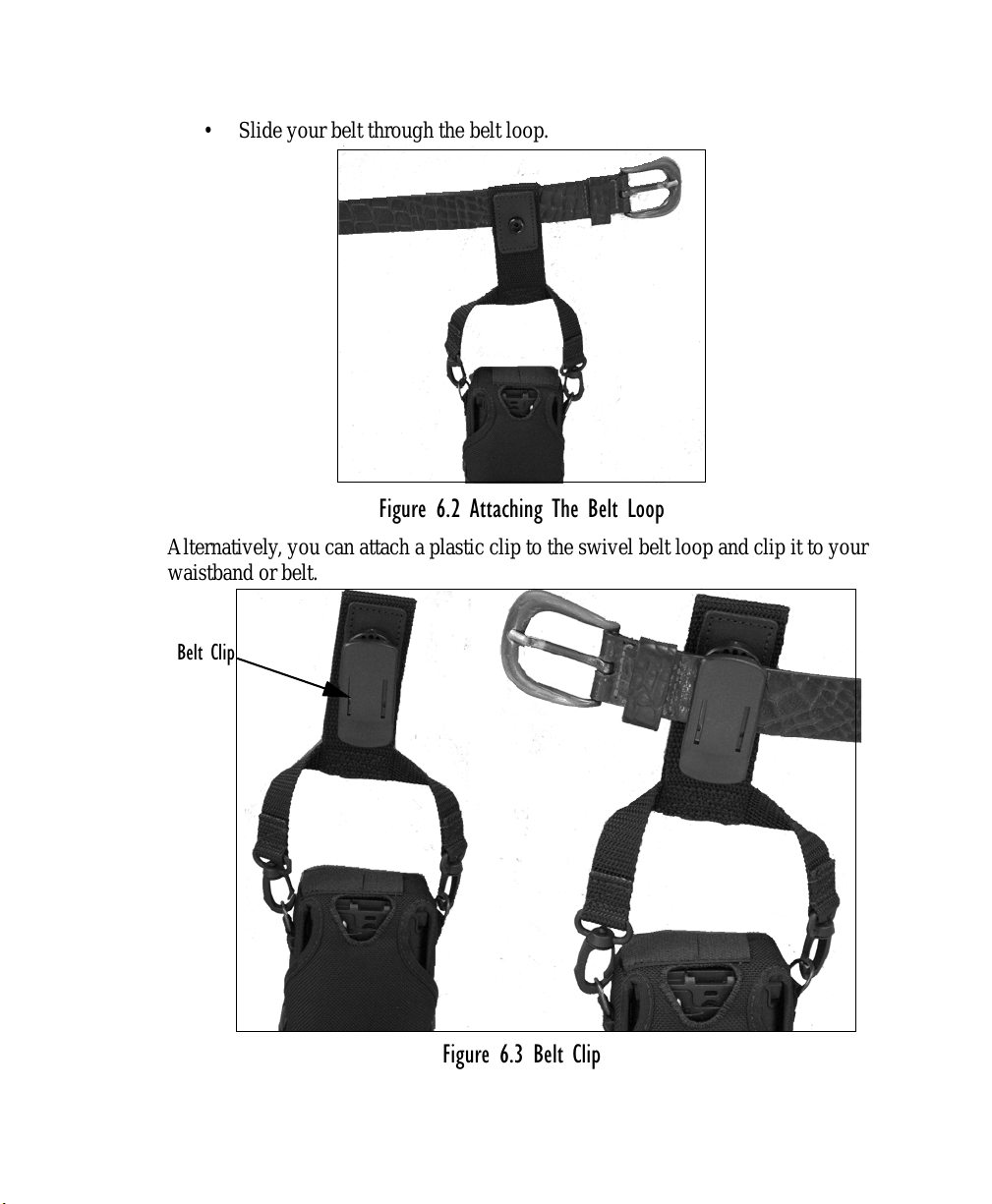
• Slide your belt thr ough t he be lt loop.
Figure 6.2 Attaching The Belt Loop
Alternatively, you can attach a plastic clip to the swive l bel t loop and clip it to your
waistband or belt.
Belt Clip
Figure 6.3 Belt Clip
WORKABOUT PRO Hand-Held Computer With Windows Mobile 5.0 User Manual 219
Chapter 6: Peripheral Devices & Accessories
Soft Shell Holster
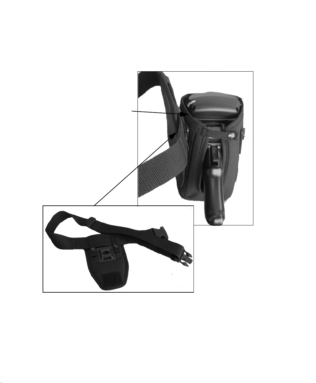
6.1.4 Soft Shell Holster
A soft shell holster with removable belt and swivel holster pad ca n be used to hang a
WORKABOUT PRO G2 with a pistol grip from you waist
Soft Shell Holster
Swivel Holster Pad and
Removable Belt
Figure 6.4 Soft Shell Holster
• Insert the belt in the swivel holster pad.
• Attach the pad on eit her t he l ef t or right side of the holster case, de pendi ng
on whether you are left- or r ight-handed.
• Fasten the belt comfortably around your waist. Sli de t he a djustable ring on
the belt to tighten the hol st er i n pl ace.
220 WORKABOUT PRO Hand-Held Computer With Windows Mobile 5.0 User Manual
Chapter 6: Peripheral Devices & Accessories
The Batteries
6.2 The Batteries
The WORKABOUT PRO G2 will operate with a High-Capacit y Lit hium I on
battery pack, a Super High-Capacity Lithium Ion battery pack.
In addition to the main batte ry, the hand-held is equipped wit h a re chargable coin
battery
–a Maxell ML2032.
6.3 Chargers And Docking Stations
Important: Keep in mind when ordering a charger or docking station, you
must also order the appropriate power cord separately.
Psion Teklogix offers a variety of chargers and docking stations for the
WORKABOUT PRO G2. These include:
• Single Battery Charger
• Quad Battery Charger
• Desktop Docking S t ati o n
• Quad Docking Station
–Model No. WA3001-G1
–Model No. WA3004-G1
–Model No. WA4003-G2
–Model No. WA4004-G1
6.3.1 Installation–Chargers And Docking Stations
When installing a char ger o r doc king station, consider the follo wi ng gui del ine s.
• Keep chargers and docking stations away from excessive dirt, dust and
contaminants.
• Chargers will not charge batteries outside an ambient temperature range
of 0° C to 45 °C (32° F to 1 1 3° F). It is recommended that the charger or
docking station b e oper ated a t ro om t emperatur e
(64° F to 77° F) for maximum performance .
After unpacking your unit :
• Visually inspect the charger for po ssi ble damage.
• Install the IEC power cord and apply power.
–between 18° C and 25° C
6.3.2 Power Consumption Considerations
Check to ensure the mains circuit supplying chargers and/or docking stations is
adequate for the load, especially if several char ger s and docking stations are being
powered from the same circuit.
• Quad charge r
–can consume up to 2A @ 120VAC or 1A @ 240VAC.
WORKABOUT PRO Hand-Held Computer With Windows Mobile 5.0 User Manual 221

Chapter 6: Peripheral Devices & Accessories
Operator Controls
• Quad docking station–can consume up to 3A @ 120VAC or 1.5A @
240VAC.
6.3.3 Operator Controls
WORKABOUT PRO G2 docking stations and chargers have no op erator controls or
power switches.
6.3.4 Important Charger Safety Instructions
• SAVE THESE INSTRUCTIONS–This manual contains important safety and
operating instructions for battery charger s.
• Before using the battery charger, read all instructions and cautionary
markings on (1) battery charger, (2) battery, and (3) product using battery.
• The mains power cord shall comply with national safety regulat ions o f the cou ntr y
where the equipment is to be sold.
• Use of an attachment not recommended or sold by the battery charger
manufacturer may result in fire, electric shock, or personal injury.
• To reduce risk of damage to the electric plug and cord when unplugging the
charger, pu ll the plug rather than the cord.
• Make sure the cord is positioned so that it is not stepped on, tri pped ov er,
or otherwise subjected to damage or stress.
• Do not operate the charger with a damaged cord or plug.
Replace immediately.
• Do not operate the charger if it has received a sharp blow, been dropped, or oth erwise damaged in any way; it should be inspected by qualifi ed servi ce personn el.
• Do not disassemble the charger; it should be repaired by qualified servi ce person nel. Incorrect reassembly may result in electric shock or fire.
• To reduce risk of electric shock, u npl ug the charger from the outlet before
attempting any maintenance or cleaning.
• An extension cord should not be used unless absolutely necessary. Use of an
improper extension cord could result in fire or electric shock.
If an extension cord must be used, make sure:
• The plug pins on the extension cord are the same number , s ize,
and shape as those on the charger.
• The extension cord is properly wired and in good electrical
condition and that the wire size is larger than 16 AWG.
• Do not expose the charger to rain or snow.
• Do not place batteries in the charger if they are cold from extended
exposure to a freezer or outside temperatures below 10°C (50°F). Allow them to
warm up to room temperature for at least two hours.
222 WORKABOUT PRO Hand-Held Computer With Windows Mobile 5.0 User Manual
 Loading...