

Page 1
Installationsanweisung
Schneider Aufrüst-Kit
Installation Guide
Kit Cutter Upgrade
PP 803
Part: 8707 330 90506
Page 2
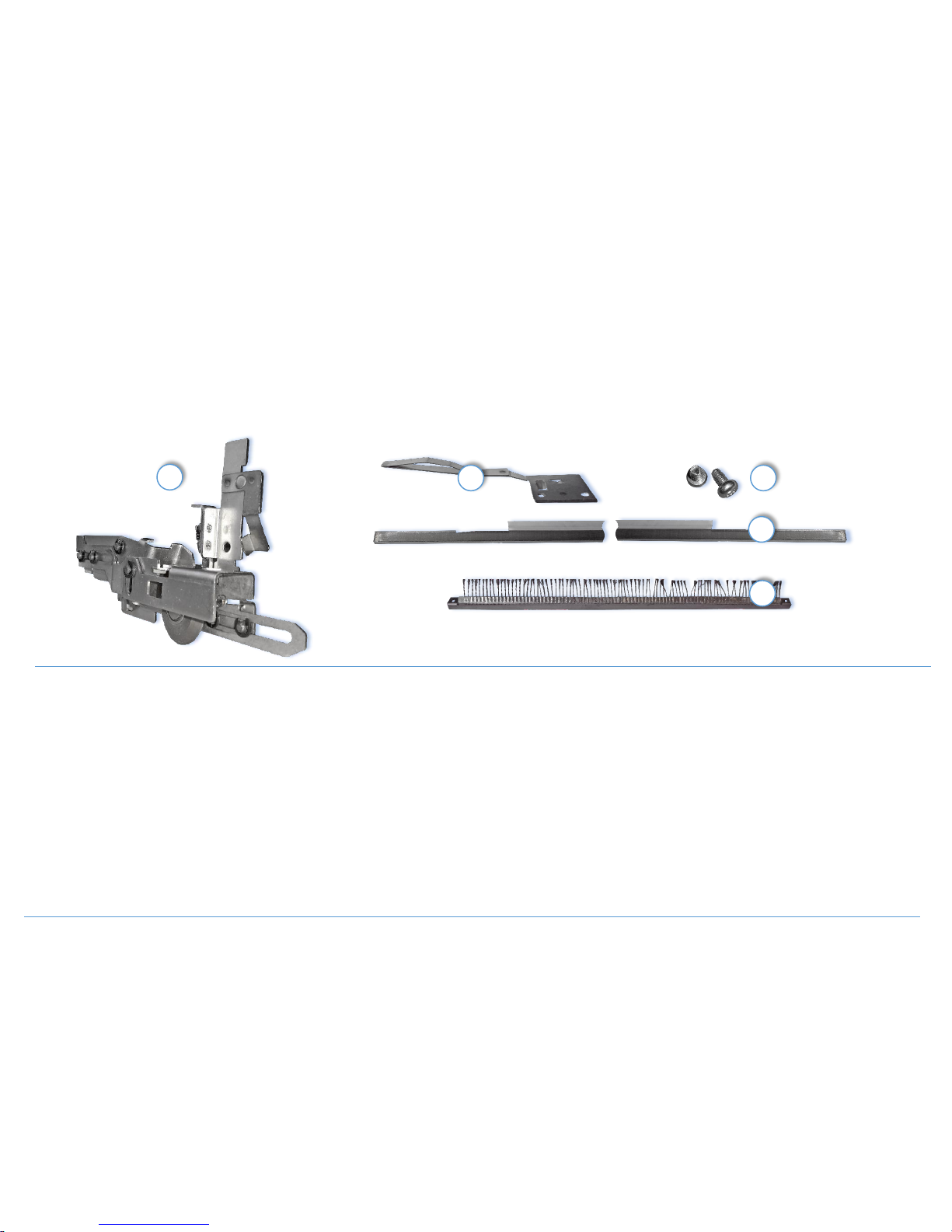
Contents of the Kit Cutter upgrade:
Cutter PP80X (A)
Cutter Bar PP803 with plastic stripe on lower side (B)
Paper Holder Hold-Down Cutter (C)
Screws 2x (D)
Tear bar with anti-static brush (E)
Inhalt des Schneider Aufrüst-Kits
Schneider PP80X (A)
Schneidbalken PP803 mit Plastikfolie auf der Unterseite (B)
Niederhalter (C)
2x Schraube (D)
Abreißschiene mit Antistatik-Bürste (E)
A Publication of PS i Mat rix GmbH
Hommeswi es e 116c
57 258 Freude nb er g · Germany
ht tp://w ww .p si - m atrix.eu
Pub. N o. 511 2-99 1-19873
Great care has been taken, to ensure that the information in this handbook is accurate and complete. Should any errors or omissions be discovered, however, or should any user wish
to make suggestions for improving this handbook, he is invited to send us the relevant details.
The content of this manual are subject to change without notice. Copyright © by PSi Matrix GmbH.
All right strictly re served. Reproduction or issue to third parties in any form whatever is not permitted without written authority from t he publisher
A
C B E
D
Page 3
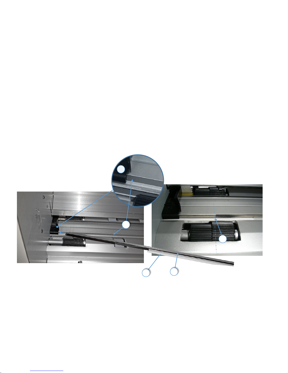
Installing of the Cutter Bar (1)
Attention: Danger to injure one’s hand by the bar!
Please check, that the plastic stripe (2) neither extends the rear long side nor
one of the small sides of the bar. Otherwise cut it.
Insert the Cutter Bar (1) with the plastic stripe (2) on the lower side into the
Aluminum Profile (3) and shift it to left side until it touches the left metal wall.
Do not stop shifting at the black plastic guide (4). Pos. (5) shows the end position
of the bar relative to the gear wheel
Installieren des Schneidebalkens (1)
Achtung: Die Schneidkante ist sehr scharf Verletzungsgefahr!
Bitte überprüfen Sie, dass der Kunststoffstreifen (2) auf der Längsseite rechts
und links nicht übersteht. Ansonsten auf Gesamtlängen kürzen
Legen Sie den Schneidbalken (1) mit dem Kunststoffstreifen (2) nach unten in
das Aluminiumprofil (3) und verschieben ihn ganz nach links unter die
Farbbandführung rechts (4), bis er die linke Metallwand berührt. Pos. (5) zeigt
die Endposition der Stange relativ zu dem Zahnrad.
2
1
4
3
5
Page 4
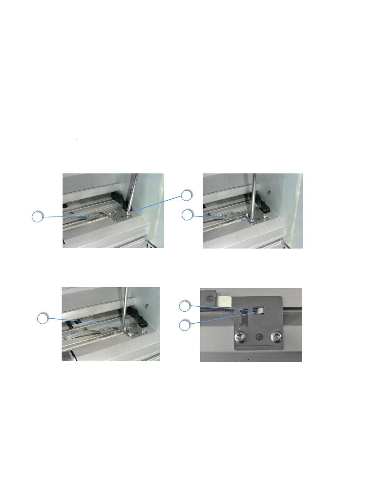
Mounting of the Paper Holder (6)
First fix the Paper Holder with the outer screw (7), first not tightly but loosely.
Then carefully fix the inner screw (8) and finally fix the outer screw (7) but
carefully.
The rear side (9) of the metal sheet must closely contact the aluminium profile.
The metal nose (10) has to be placed behind the end of the bar. The nose (11)
contacts the sharp edge of the bar.
Montieren des Niederhalters (6)
Befestigen Sie zuerst den Niederhalter mit der äußeren Schraube (7) zunächst
aber locker (nicht festziehen).
Fixieren Sie dann vorsichtig die rechte Schraube (8) und ziehen diese vorsichtig
fest. Anschließend die linke Schraube (7) vorsichtig festziehen.
Die Metallnase (10) an der Rückseite des Blechs (9) muss genau an dem
Aluminiumprofil anliegen.. Die Nase (11) hält die Schneidleiste als rechter
Anschlag fest.
678
91011
Page 5
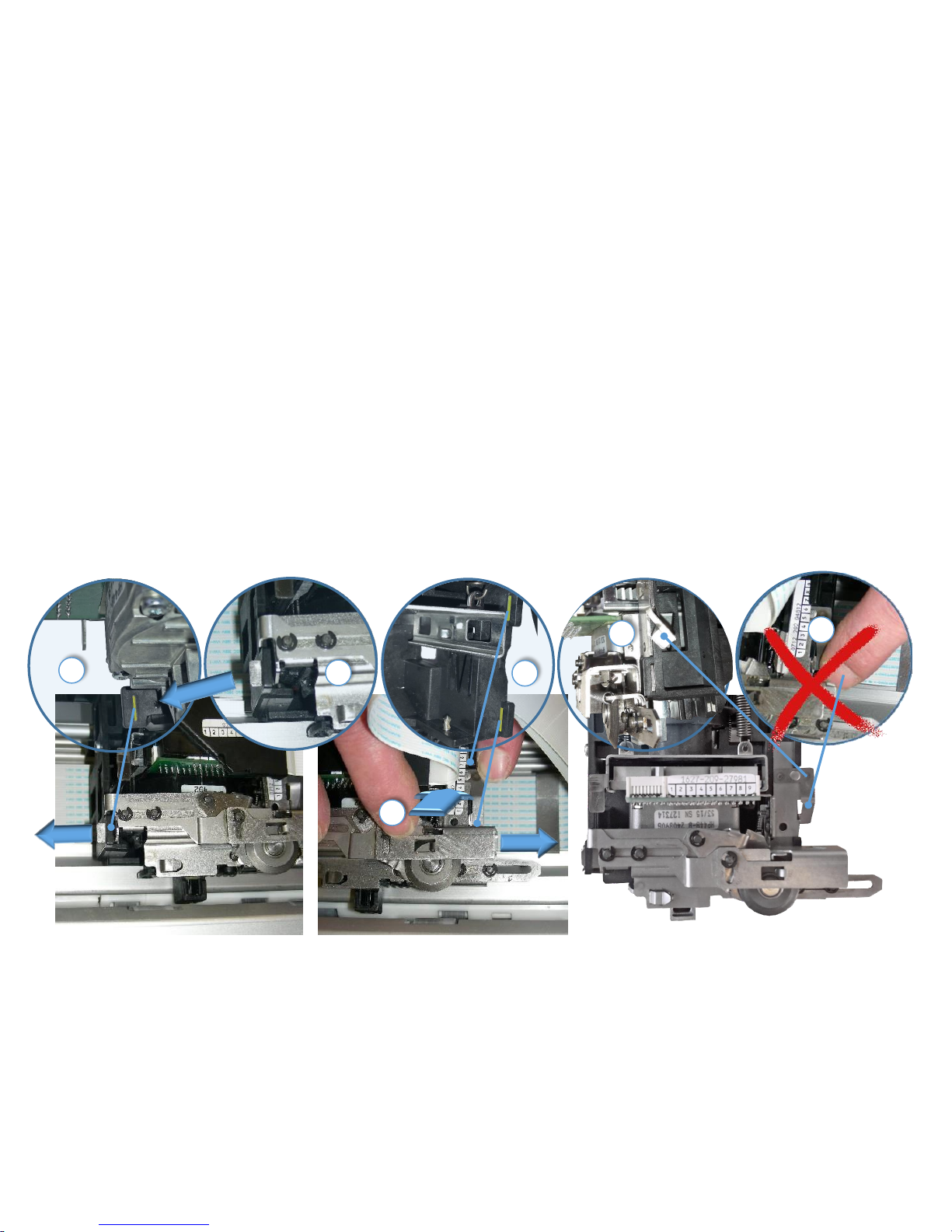
Installing the Cutter (12)
Attention: Danger to injure one’s hand by the blade or cutting wheel!
If not done yet, first adjust the cutter usage in the Printer Menu:
LOCAL -> INSTALLATION->CUTTING DEVICE -> YES->ENTER
LOCAL -> SAVE MENU
Insert the Paper Cutter (12) side slide into the aperture (13) at the left of
the carriage. Then press only in the position (16) cutter to the back and
to the right side into the two apertures (14) of the carriage and shift the
cutter slightly to the right until the right noses of the cutter fits into the
slits (15). The cutter will automatically lock. The locking lug (17) must not
be pushed backwards.
Installieren des Schneiders (12)
Achtung: Verletzungsgefahr am Schneidrad!
Falls noch nicht geschehen, zunächst den Schneider im Menü aktivieren:
STOP -> INSTALLATION-> SCHNEIDER -> JA-> ENTER
STOP -> SPEICHERN MENÜ
Den Schneider (12) in die Öffnung (13) auf der linken Seite des
Druckschlittens schieben. Drücken Sie dann nur auf der Position (16) den
Schneider nach hinten und dann nach rechts in die beiden Öffnungen
(14) des Druckschlittens, bis die rechte Rastnasen des Schneiders in die
einrastet (15) und automatisch verriegelt. Die Rastnase (17) nicht nach
hinten drücken.
121314
131615
17
Page 6
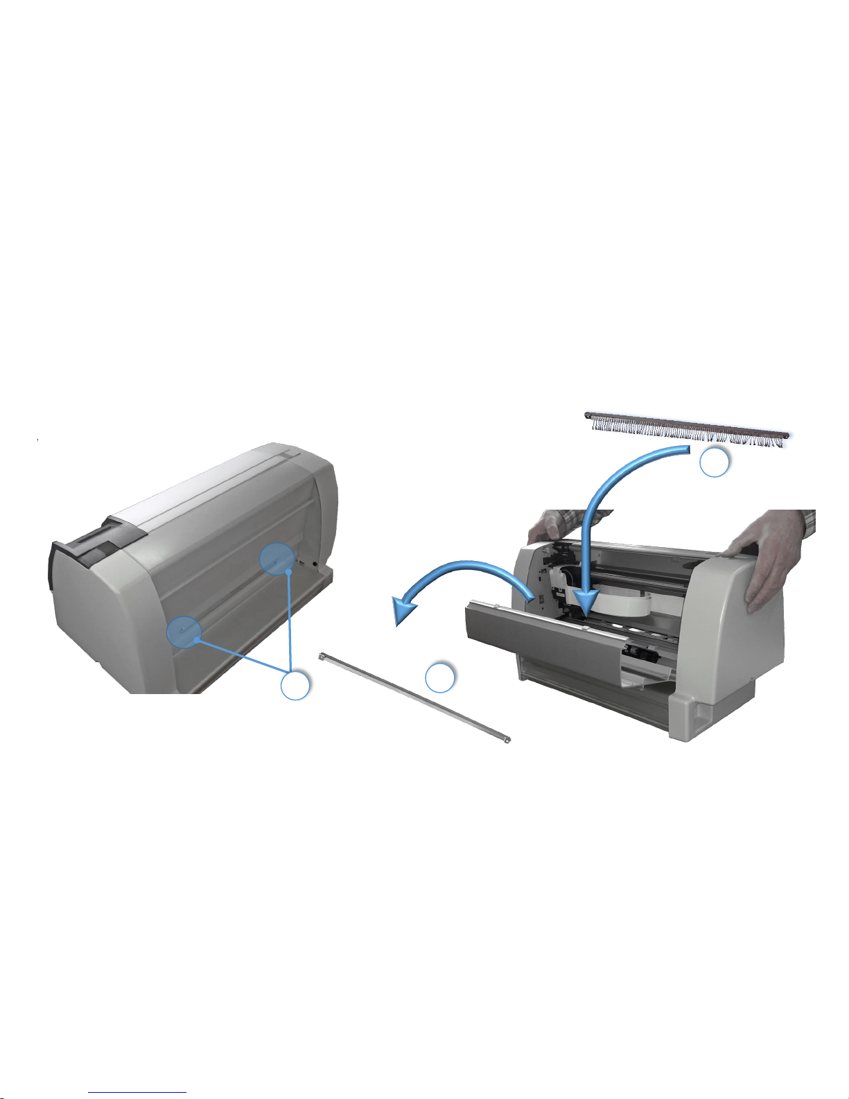
Installation of the Tear-off-bar with anti-static brush (18)
unscrew the installed Tear-off-bar (20) open the printer and remove the
bar.
Put in the tear-off-bar with anti-static brush close cover and fix it with
the screws.
Installieren der Abreißschiene mit Antistatik-Bürste (18)
Die Schrauben (19) der vorhandenen Abreißschiene (20) entfernen. Die
Rückwand öffnen (20) und die Schiene entnehmen.
Die Abreißschiene mit Antistatik-Bürste einlegen und Rückwand
schließen. Die Schrauben wieder ansetzen und festziehen.
19
18
20
Page 7
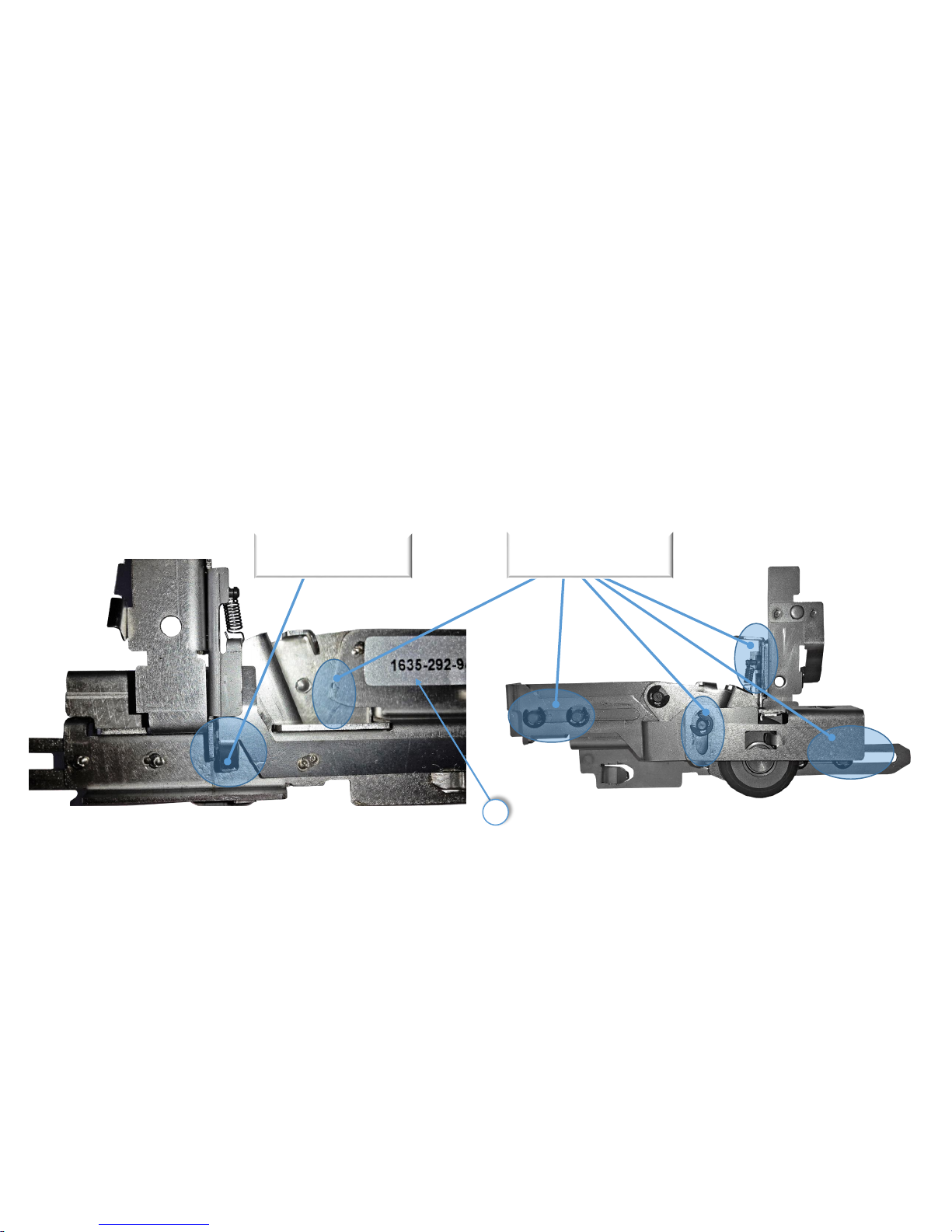
Preventive maintenance of cutter moving parts
Recommended frequency of all cutter moving parts cleaning and lubrication:
approxiamately 250,000 cut-cycles
Greasing points are blue marked (e.g. use lubricating grease POLYLUB GLY 151).
For service requests: Here (21) you find the date code and the technical part
number of the cutter installed.
Vorbeugende Wartung der beweglichen Teile des Schneiders
Empfohlene Frequenz aller Schneider beweglichen Teile Reinigung und
Schmierung:
Ca.250.000 Schneid-Zyklen
Schmierstellen sind blau markiert (Schmier-Fett POLYLUB GLY 151 verwenden).
Für Service-Anfragen: finden Sie hier (21) des Produktions-Datum und die
technischen Nummer des installierten Schneider.
Grease the black pin!
Schwarzen Stift schmieren!
Grease these moving parts!
Bewgliche Teile schmieren!
21
 Loading...