

User's Manual
High Speed Fanfold Printer
High Speed Fanfold Printer with Cutter

Acknowledgements
EPSON is a Trademark of Seiko Epson Corporation.
IBM is a Trademark of International Business Machines Corporation.
ProPrinter is a Trademark of International Business Machines Corporation.
A Publication of PSi
Matrix GmbH
Hommeswiese 116c
D – 57258 Freudenberg
Federal Republic of Germany
August 2014
http:\\www.psi-matrix.eu
Great care has been taken to ensure that the information in this handbook is accurate and complete. However,
should any errors or omissions be discovered or should any user wish to make suggestions for improving this
handbook, please feel encouraged to send us the relevant details.
The contents of this manual are subject to change without notice. Copyright © by
PSi Matrix GmbH.
All rights strictly reserved. Reproduction or issue to third parties in any form is not permitted without written
authorization from the publisher.

I
Safety Regulations
The printers PP 407 (High Speed Fanfold Printer) and the
PP 408 (High Speed Fanfold Printer with Cutter) fulfils the safety regulations
according to EN 60950-1, UL 60950-1 and CAN/CSA 22.2/No. 60950-1 for
Information Technology Equipment.
The mains cable must be connected to a ground protected wall-socket. The
indicated voltage of the printer needs to agree with the local voltage.
The power plug must be easily accessible at any time so that it can be
disconnected immediately in case of danger or for maintenance purposes..
Comme le câble de secteur sert de dipositif d'arrêt-urgence, sa connexion à
l'imprimante doit être tout le temps accessible.
Before installing the printer, check the surrounding conditions in which the
printer will be placed (see next page, Operating Environment and chapter 1).
During a thunderstorm you should never attempt to connect or disconnect any
data transfer cables.
The power supply should only be opened and checked by authorized personnel.
Repairs and maintenance beyond the descriptions of chapter 3 Maintenance
may only be attempted by authorized personnel as well. Repairs done
inappropriately may cause damage and severe danger for the user.
There are warning symbols to draw the user's attention to possible injuries:
This symbol is visible when the top cover has been opened.
It indicates that the print head is extremely hot after long
periods of printing.
This symbol is located on the cover of the cutting device. It
cautions against touching the blade.

4
Safety Regulations
Electromagnetic Compatibility
We certify that the equipment at issue,
S Printer PP 407 (High Speed Fanfold Printer) and
S Printer PP 408 (High Speed Fanfold Printer with Cutter)
corresponds to the law regulations ruling electromagnetic compatibility of
appliances (2004/108/EC) and, therefore, fulfils the requirements for conformity
marking with the CE-sign.
To assure the compliance with the limiting values in according to the test
standards for interference (EN 55022, class B) and noise immunity (EN 55024),
shielded interface cables must be used.
This equipment has been tested and found to comply with the limits for a
Class B digital device, pursuant to Part 15 of the FCC rules. These limits are
designed to provide reasonable protection against harmful interference in a
residential installation. This equipment generates, uses, and can radiate radio
frequency energy and, if not installed and used in accordance with the instruction manual, may cause interference to radio communications.
However, there is no guarantee that interference will not occur in a particular
installation. If this equipment does cause harmful interference to radio or
television reception, it can be determined by turning the equipment off and on.
The user is encouraged to try to correct the interference by one or more of the
following measures:
S Reorient or relocate the receiving antenna.
S Increase the separation between the equipment and receiver.
S Connect the equipment to an outlet on a circuit different from the circuit to
which the receiver is connected.
S Consult the dealer or an experienced radio/TV technician for help.
Shielded interface cables should be used with this unit to ensure compliance
with Class B limits.
Changes and modifications not explicitly allowed by the equipment's
manufacturer could void the user's authority to operate the equipment.
Changes et modifications pas expressément approuvés par le producteur
peuvent dévaluer l'autorité d'opérer l'équipement.

III
Safety Regulations
Operating Environment
Avoid installing the printer where it is exposed to moisture or heat (eg. direct sun
light).
S Temperature: + 10°C to + 35°C (+50°F to +95°F)
S Humidity: 20% to 80%
Slots and openings in the printer's housing are provided for ventilation. Always
ensure that these openings are not obstructed.
Also ensure that the cables at the rear of the printer do not interfere with the
output paper path.


5
Table of Contents
Preface . . . . . . . . . . . . . . . . . . . . . . . . . . . . . . . . . . . . . . . . . . . . . . . . . . . . . . XI
About this Manual . . . . . . . . . . . . . . . . . . . . . . . . . . . . . . . . . . . . . . . . . . . . . . XI
Conventions used in this Guide . . . . . . . . . . . . . . . . . . . . . . . . . . . . . . . . . . . XIII
1.
Getting Started ......................................................................................... 1-1
1.1 Unpacking the High Speed Fanfold Printer ........................................... 1-1
1.1.1 A First Look to the High Speed Fanfold Printer ............................... 1-2
1.2 Unpacking the High Speed Fanfold Printer with Cutter ......................... 1-3
1.2.1 A First Look at the High Speed Fanfold Printer with Cutter ............. 1-4
1.2.2 Mounting the Cutting Device ........................................................... 1-5
1.3 Site Consideration ................................................................................ 1-6
1.4 Transport Lock ...................................................................................... 1-7
S Repacking Information
1.5 Installing the Personality Module .......................................................... 1-8
1.6 The Power Supply ................................................................................ 1-9
S Main Voltage
1.7 Power ON/OFF Switch ....................................................................... 1-10
1.8 Installing the Ribbon Cassette ............................................................ 1-11
1.8.1 Replacing the Ribbon Cassette ..................................................... 1-14
1.9 Inserting Fanfold Paper ....................................................................... 1-15
......................................................................................... 1-9
S Handling of the Tractor Cassettes
1.10 Selection of Operator Panel Language ............................................... 1-17
1.11 Paper Source Selection ...................................................................... 1-18
1.12 Test Prints .......................................................................................... 1-19
S PRINT TEST 1
S PRINT TEST 2
.................................................................................... 1-19
.................................................................................... 1-20
S To start a print test
1.13 Connection to a Computer .................................................................. 1-22
S Parallel, Serial, or USB Interface
.................................................................... 1-7
...................................................... 1-15
.............................................................................. 1-21
........................................................ 1-22

Safety Regulations
6
1.14 Emulation Selection ............................................................................ 1-23
2.
Printer Operation ....................................................................................... 2-1
2.1 Control Panel ................................................................ .......................... 2-1
2.2 Function Keys......................................................................................... 2-2
2.2.1 Short Description of Keys .................................................................. 2-2
S in the printer operation state READY or BUSY ............................ 2-2
S in the printer operation state LOCAL ........................................... 2-2
2.2.2 Detail Description of Keys in the printer operation
state READY or BUSY ...................................................................... 2-3
S Quick Settings .............................................................................. 2-3
S Top Row Keys.............................................................................. 2-4
S Lower Row Keys .......................................................................... 2-4
2.2.3 Meaning of the Keys in the LOCAL Mode ......................................... 2-7
S Lower Row Keys .......................................................................... 2-7
2.3 Menu Mode ............................................................................................ 2-8
2.3.1 To Activate the Menu ........................................................................ 2-9
2.3.2 To Confirm Selection ...................................................................... 2-10
2.3.3 How to Save Settings ..................................................................... 2-11
2.3.4 Quick Settings ................................................................................ 2-12
3.
Maintenance ............................................................................................... 3-1
S Preferred Materials ................................................................................. 3-1
3.1 Cleaning ................................................................................................. 3-1
3.2 Cleaning Procedure ................................................................................ 3-3
3.3 User Replaceable Parts .......................................................................... 3-4
3.3.1 Replacement of the Print Head ......................................................... 3-4
S Print Head Removal .......................................................................... 3-4
S Print Head Installation ....................................................................... 3-5
3.3.2 Replacement of the Platen ................................................................ 3-6
S Remove the Platen ............................................................................ 3-6
S Install the Platen ................................................................................ 3-7
4.
Trouble Shooting and Diagnostics .......................................................... 4-1
S How to Use this Section
........................................................................ 4-1

7
4.1 Power-related Problems ........................................................................ 4-2
4.2 Error Messages ..................................................................................... 4-2
4.2.1 Errors during Selftest ........................................................................ 4-2
4.2.2 Errors during Printing ....................................................................... 4-4
4.2.3 Technical Errors ............................................................................... 4-6
4.3 No Printout ............................................................................................ 4-7
4.4 Operation-related Problems ................................................................... 4-8
4.5 Print-related Problems ........................................................................... 4-9
4.6 Paper Jam ........................................................................................... 4-11
4.7 Ribbon or Carriage-related Problems .................................................. 4-13
4.8 Print Test ............................................................................................. 4-13
4.9 Diagrams of Errors .............................................................................. 4-14
4.9.1 Paper Jam TRF .............................................................................. 4-14
4.9.2 No Printout / No Printing ................................................................. 4-15
4.9.3 Print Faint or of Poor Quality .......................................................... 4-16
5.
Technical Data .......................................................................................... 5-1
S Label Processing
................................................................................... 5-9

Table of Contents
VIII
A. Configuring the Printer . . . . . . . . . . . . . . . . . . . . . . . . . . . . . . . . . . . . . A-1
A.1 What is Configuring . . . . . . . . . . . . . . . . . . . . . . . . . . . . . . . . . . . . . . A-1
A.2 Standard Configuration . . . . . . . . . . . . . . . . . . . . . . . . . . . . . . . . . . . A-3
A.2.1
for the High Speed Fanfold Printer . . . . . . . . . . . . . . . . . . . . . . . A-3
A.2.2
for the High Speed Fanfold Printer with Cutter . . . . . . . . . . . . . A-4
A.3
Explanation of the Printout on the previous page . . . . . . . . . . . . . . . . A-5
A.4
Explanation of Individual Menu Items . . . . . . . . . . . . . . . . . . . . . . . . . A-6
Main Functions . . . . . . . . . . . . . . . . . . . . . . . . . . . . . . . . . . . . . . . . . . . A-6
S MACRO SELECT . . . . . . . . . . . . . . . . . . . . . . . . . . . . . . . . . . . . . . . . A-6
S CHANGE MACRO . . . . . . . . . . . . . . . . . . . . . . . . . . . . . . . . . . . . . . . A-6
S INSTALLATION . . . . . . . . . . . . . . . . . . . . . . . . . . . . . . . . . . . . . . . . . A-6
S SAVE . . . . . . . . . . . . . . . . . . . . . . . . . . . . . . . . . . . . . . . . . . . . . . . . . A-6
S PRINT OUT . . . . . . . . . . . . . . . . . . . . . . . . . . . . . . . . . . . . . . . . . . . . A-7
Main Function CHANGE MACRO . . . . . . . . . . . . . . . . . . . . . . . . . . . . . A-7
S FONT . . . . . . . . . . . . . . . . . . . . . . . . . . . . . . . . . . . . . . . . . . . . . . . . . A-7
S PRINT QUALITY . . . . . . . . . . . . . . . . . . . . . . . . . . . . . . . . . . . . . . . . A-8
S GRAPHICS QUALITY . . . . . . . . . . . . . . . . . . . . . . . . . . . . . . . . . . . . A-8
S SUB/SUPER FONT . . . . . . . . . . . . . . . . . . . . . . . . . . . . . . . . . . . . . . A-8
S PITCH . . . . . . . . . . . . . . . . . . . . . . . . . . . . . . . . . . . . . . . . . . . . . . . . A-8
S LINE . . . . . . . . . . . . . . . . . . . . . . . . . . . . . . . . . . . . . . . . . . . . . . . . . . A-8
S PAPER LENGTH . . . . . . . . . . . . . . . . . . . . . . . . . . . . . . . . . . . . . . . . A-9
S VERT.POS.ADJ. . . . . . . . . . . . . . . . . . . . . . . . . . . . . . . . . . . . . . . . A-10
S LEFT MARGIN . . . . . . . . . . . . . . . . . . . . . . . . . . . . . . . . . . . . . . . . . A-10
S RIGHT MARGIN . . . . . . . . . . . . . . . . . . . . . . . . . . . . . . . . . . . . . . . . A-11
S TOP MARGIN . . . . . . . . . . . . . . . . . . . . . . . . . . . . . . . . . . . . . . . . . A-11
S BOTTOM MARGIN . . . . . . . . . . . . . . . . . . . . . . . . . . . . . . . . . . . . . A-12
S PERFORATION SKIP . . . . . . . . . . . . . . . . . . . . . . . . . . . . . . . . . . . A-12
S PAPER SOURCE . . . . . . . . . . . . . . . . . . . . . . . . . . . . . . . . . . . . . . . A-12
S PAPER EXIT . . . . . . . . . . . . . . . . . . . . . . . . . . . . . . . . . . . . . . . . . . A-13
S STACK.CAPACITY . . . . . . . . . . . . . . . . . . . . . . . . . . . . . . . . . . . A-13
S BATCH CAPACITY . . . . . . . . . . . . . . . . . . . . . . . . . . . . . . . . . . . A-13
S EMULATION . . . . . . . . . . . . . . . . . . . . . . . . . . . . . . . . . . . . . . . . . . A-14
S CHARACTER SET . . . . . . . . . . . . . . . . . . . . . . . . . . . . . . . . . . . . . . A-14
S LINE MODE . . . . . . . . . . . . . . . . . . . . . . . . . . . . . . . . . . . . . . . . . . . A-14
S $$ COMMANDS . . . . . . . . . . . . . . . . . . . . . . . . . . . . . . . . . . . . . . . . A-15
S TEAR-OFF / CUT . . . . . . . . . . . . . . . . . . . . . . . . . . . . . . . . . . . . . . . A-15

Table of Contents
IX
Main Function INSTALLATION . . . . . . . . . . . . . . . . . . . . . . . . . . . . . . . . . A-17
Sub-Function INTERFACE . . . . . . . . . . . . . . . . . . . . . . . . . . . . . . . . . . A-17
S BUFFER . . . . . . . . . . . . . . . . . . . . . . . . . . . . . . . . . . . . . . . . . . . . . . A-17
S WORD LENTH . . . . . . . . . . . . . . . . . . . . . . . . . . . . . . . . . . . . . . . . . A-17
S I/F TYPE . . . . . . . . . . . . . . . . . . . . . . . . . . . . . . . . . . . . . . . . . . . . . . A-17
S BAUD RATE . . . . . . . . . . . . . . . . . . . . . . . . . . . . . . . . . . . . . . . . . . . A-18
S PARITY BIT . . . . . . . . . . . . . . . . . . . . . . . . . . . . . . . . . . . . . . . . . . . . A-18
S PROTOCOL . . . . . . . . . . . . . . . . . . . . . . . . . . . . . . . . . . . . . . . . . . . A-18
Sub-Function ADJUSTMENT . . . . . . . . . . . . . . . . . . . . . . . . . . . . . . . . A-19
S AGC POSITION . . . . . . . . . . . . . . . . . . . . . . . . . . . . . . . . . . . . . . . . A-19
S PLATEN GAP . . . . . . . . . . . . . . . . . . . . . . . . . . . . . . . . . . . . . . . . . . A-20
S AGC ADJUST . . . . . . . . . . . . . . . . . . . . . . . . . . . . . . . . . . . . . . . . . . A-20
S PAPER-IN ADJUST . . . . . . . . . . . . . . . . . . . . . . . . . . . . . . . . . . . . . A-20
S CUT. V-POS LO. / CUT. V-POS UP. . . . . . . . . . . . . . . . . . . . . . . . . . A-21
S UNI-DIRECT. CMD . . . . . . . . . . . . . . . . . . . . . . . . . . . . . . . . . . . . . . A-21
S TRACTOR FORM FEED MODE . . . . . . . . . . . . . . . . . . . . . . . . . . . . A-21
Special Menu Items under INSTALLATION . . . . . . . . . . . . . . . . . . . . A-22
S LANGUAGE . . . . . . . . . . . . . . . . . . . . . . . . . . . . . . . . . . . . . . . . . . . A-22
S RESTORE SET UP . . . . . . . . . . . . . . . . . . . . . . . . . . . . . . . . . . . . . . A-22
S RECALL FACTORY . . . . . . . . . . . . . . . . . . . . . . . . . . . . . . . . . . . . . A-22
S MENU ACCESS . . . . . . . . . . . . . . . . . . . . . . . . . . . . . . . . . . . . . . . . A-22
S SELF TEST . . . . . . . . . . . . . . . . . . . . . . . . . . . . . . . . . . . . . . . . . . . . A-23
S HEX DUMP . . . . . . . . . . . . . . . . . . . . . . . . . . . . . . . . . . . . . . . . . . . . A-23
S FIRMWARE VER. . . . . . . . . . . . . . . . . . . . . . . . . . . . . . . . . . . . . . . . A-23
Configuration Menu . . . . . . . . . . . . . . . . . . . . . . . . . . . . . . . . . . . . . . . Menu-1

Table of Contents
10
Appendix B System Interface Descriptions . . . . . . . . . . . . . . . . . . . . . . . . . B-1
1. Serial Interface RS 232 C . . . . . . . . . . . . . . . . . . . . . . . . . . . . . . . . . . . . B-2
2. Parallel Interface . . . . . . . . . . . . . . . . . . . . . . . . . . . . . . . . . . . . . . . . . . . B-3
3. Additional Information . . . . . . . . . . . . . . . . . . . . . . . . . . . . . . . . . . . . . . . B-4
4. USB Interface . . . . . . . . . . . . . . . . . . . . . . . . . . . . . . . . . . . . . . . . . . . . . B-5
Appendix C Character Set Table . . . . . . . . . . . . . . . . . . . . . . . . . . . . . . . . . C-1
Appendix D IBM ProPrinter 4207, 4208 XL 24 Quick Reference . . . . . . . . . D-1
Appendix E EPSON LQ 2550 / ESC/P2 Quick Reference . . . . . . . . . . . . . E-1 Appendix
F Barcode Quick Reference . . . . . . . . . . . . . . . . . . . . . . . . . . . . F-1
Appendix G Print Samples of Resident Fonts . . . . . . . . . . . . . . . . . . . . . . . G-1

XI
Preface
About this Manual
This manual is covering the two printers
– High Speed Fanfold Printer
– High Speed Fanfold Printer with Cutter
The operation and functionality are nearly the same. In most illustrations, the
High Speed Fanfold Printer with Cutter is used. In case there are differences
in the handling you will find the note:
S High Speed Fanfold Printer
or
S High Speed Fanfold Printer with Cutter
The Interface (Personality Module (PM)) is an integral part of the printer, and the
type of PM used, determines the functionality of the printer especially regarding
the user and system interface.
The manual is divided into the following chapters:
1.
Getting Started
This chapter covers the unpacking and setting-up of the printer and the
installation of the PM (Personality Module) and ribbon cassettes. By the end
of this chapter the printer should be fully functional and tested in its primary
form. It is not yet connected to the host computer system and no options are
mounted.
2.
Operating the Printer
This chapter discusses in detail the operation of the operator panel, all menu
functions, and the general operation of the menu.

Preface
12
3.
Maintenance
Shows how to clean the printer and how to replace the platen and the print
head.
4.
Trouble Shooting and Diagnostics
Suggests how to identify and correct simple problems.
5.
Technical Data
All technical details or data about the printer can be found here.
Appendix
A. Configuring the Printer
This chapter explains how to configure the printer so that it can communicate
with the corresponding system environment. Then this chapter thoroughly
describes the printer's operating controls. In the last part you will find
explanations of individual menu items. At the end of this chapter you will find
the Menu tree.
B. Interface Description
This chapter gives hints about possibilities to connect the printer to the
various computer systems and explains particularities depending on the
version of the operating system. Additionally, cable connection is illustrated.
C. Character Set Table
All printer supported character sets are listed in this chapter.
D. Control Codes
Quick reference for IBM ProPrinter and IBM ProPrinter AGM (4207, 4208 XL
24) Emulation.
E. Control Codes
Quick reference for EPSOM LQ 2550 / ESC/P2 Emulation.
F. Control Codes
Quick reference for Bar code programming.
G. Print Samples of Resident Fonts

14
AGC
Automatic Gap Control
EE
Eastern European
LCD
Liquid Crystal Display
LED
Light Emitting Diode
LQ
Letter Quality
MACRO
User defined group (1 bis 4) of stored parameter
NLQ
Near Letter Quality
PM
Interface (Personality Module)
Conventions Used in this Guide
The following conventions are used:
Bold Headlines and important information.
Note: Contains special advice to facilitate handling.
Caution: Contains important information to prevent damage
of the equipment.
[ENTER] Key functions are always depicted in brackets or
you will find the symbol of the key e.g .
Abbreviations and Acronyms
Preface
1-1
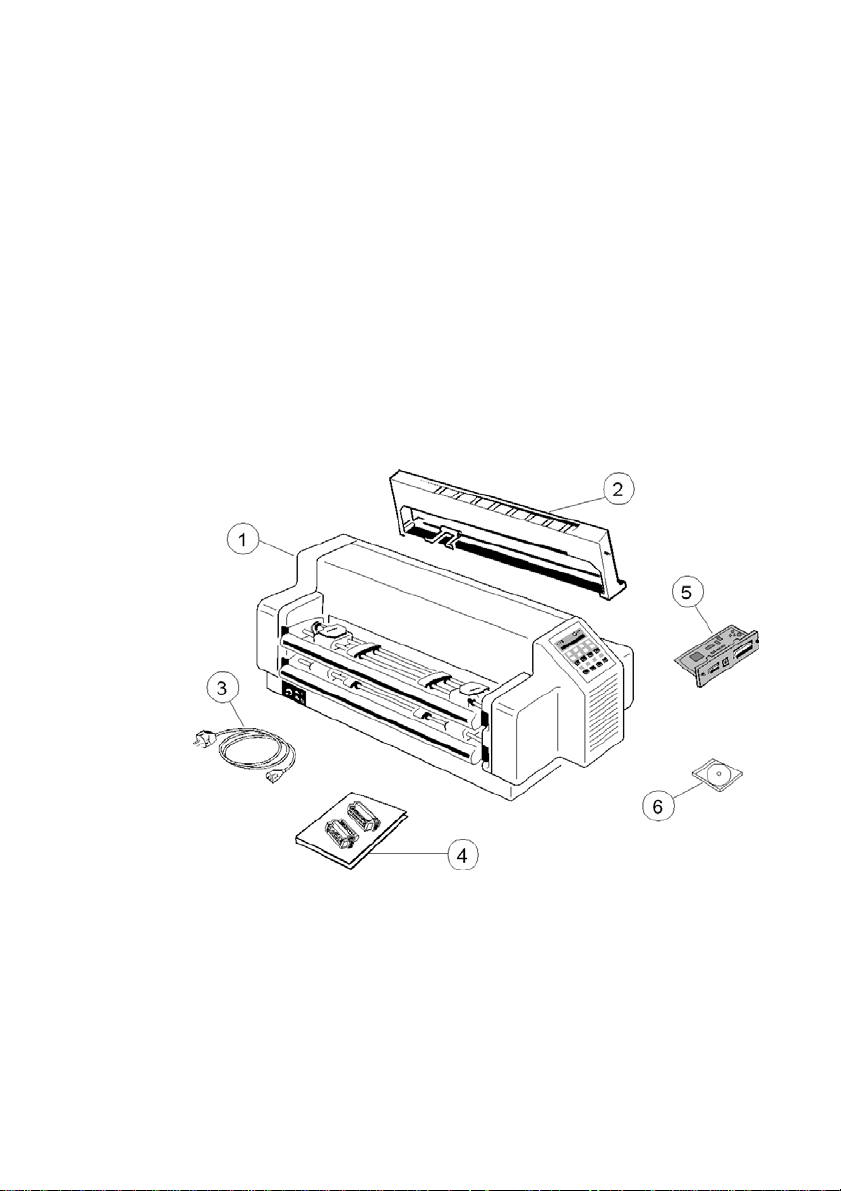
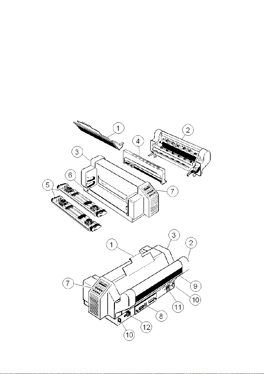
S
24-Needle Printer (1)
–
Ribbon Cassette (2)
S
Power Cord (3)
–
Quick Reference Guide (4)
S
Personality Module (PM) (5)
–
CD-ROM (6)
1. Getting Started
1.1 Unpacking the High Speed Fanfold Printer
Check each item against the check list detailed below. Contact your reseller
immediately if any item is missing or damaged.
The printer package should contain the following parts:
An interface module (5), also called “Personality Module” or briefly “PM”, is in a
separate packing.
Note: Do not connect to the mains until the main's voltage setting has been
checked (see 1.6 The Power Supply), the transport lock has been
removed (see paragraph 1.4 Transport Lock), and the PM is installed
(see 1.5 Installing the Personality Module). The printer drivers for
Windows ® are available on the enclosed CD-ROM.
Getting Started
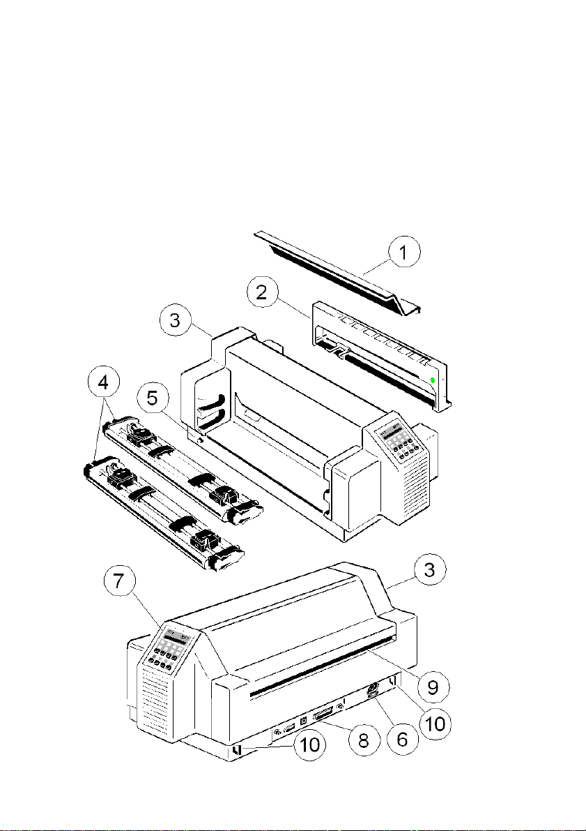
1.1.1 A First Look at the High Speed Fanfold Printer
Before installing the printer, spend some time familiarizing yourself with the
printer.
S Top Cover (1) – Power Cord Socket (6)
S Ribbon Cassette (2) – Control Panel (7)
S Printer (3) – PM serial, parallel, USB (8)
S Tractor Cassettes (4) – Tear Off Edge (9)
S Power Switch (5) – Cable Clip (10)
1-2

Getting Started
1-3
1.2 Unpacking the High Speed Fanfold Printer with Cutter
Check each item against the check list detailed below. Contact your reseller
immediately if any item is missing or damaged.
The printer package should contain the following parts:
S 24-Needle Printer (1) – Ribbon Cassette (2)
S Top Cover (2) (separate packing - see Packing Note)
S Cutting Device (3) (separate packing - see Packing Note)
S Power Cord (4) – Ribbon Cassette (5)
S CD-ROM (6) – Personality Module (PM) (7)
S Quick Reference Guide (8)
An interface module (5), also called “Personality Module” or briefly “PM”, is in a
separate packing.
Note: Do not connect to the mains until the main's voltage setting has been
checked (see 1.6 The Power Supply), the transport lock has been
removed (see paragraph 1.4 Transport Lock), and the PM is installed (see
1.5 Installing the Personality Module). The printer drivers for Windows ®
are available on the enclosed CD-ROM.
Getting Started
1-4
1.2.1 A First Look at the High Speed Fanfold Printer with Cutter
Before installing the printer, spend some time familiarizing yourself with the
printer.
S Top Cover (1) – Control Panel (7)
S Cutting Device (2) – PM serial, parallel, USB (8)
S Printer (3) – Paper output / Tear Off Edge (9)
S Ribbon Cassette (4) – Cable Clip (10)
S Tractor Cassettes (5) – Power Cord Socket (11)
S Power Switch (6) – Cutter Connector (12)
Getting Started
1-5
1.2.2 Mounting the Cutting Device (only for High Speed Fanfold Printer with
Cutter)
S Insert the pins (3) of the Cutting Device (2) into the mounting plate (4).
S Swivel the Cutting Device (2) to the Printer (1) and push the support plates (5)
onto the pins (6).
S Press the Cutting Device (2) toward to the printer so, that the retainers (7) lock
visible and with an audible click.
S Push in the plug (8) into the socket (9) and hand tighten the two lock
screws (10).
S Insert the top cover.

Getting Started
1-6
1.3 Site Considerations
Environment Conditions
S Install the printer in an area away from any heat source, air conditioner or
strong draught.
S Avoid installing the printer in a dusty or humid environment.
Work Location
S Place the printer on the stand or a flat, solid level area such as a desk.
S Slots and openings in the printer's housing are provided for ventilation; always
ensure that these openings are not obstructed.
S Always place the printer with its front edge slightly off the edge of the table
when processing fanfold paper.
S Also ensure that the cables at the rear of the printer do not interfere with the
output paper path.
Power Requirements
S No special wiring is required. A typical office wall outlet is sufficient.
S Do not plug in other equipment besides the printer such as coffee machines,
copy machines or air conditioners into the same wall outlet.

Getting Started
1-7
1.4 Transport Lock
In delivery condition a red shipping tab is visible under the top cover (1), which is
attached with the transport locking clip (2).
Lift up the top cover (1) and remove the transport locking clip (2) from the print
head drive belt.
Repacking Information
Save all packing material and boxes for future transportation of the printer.
To ensure maximum protection when transporting the printer, please pay
attention to the following:
S Push the output stacker into the top cover and pack it separately.
S Remove the power cord.
S Remove the ribbon cassette.
S Reposition the transport locking clip.
S Dismantle the Cutter Unit and pack it separately.
S Pack the complete printer in its original packing box and ship it.
Pay attention to the 'Packing Note'!

Getting Started
1-8
1.5 Installing the Personality Module
The printer functions only in combination with an installed interface module,
called a Personality Module (PM).
The illustration below shows the standard PM with a serial, parallel, and USB
interface.
Note: ) To avoid damage due to electrostatic discharge, do not touch the pins or
components of the PM.
) Never attempt to install or remove a PM while the printer is switched ON.
1.
The Printer must be powered off!
2.
Remove the PM (1) from its packing material.
3.
Insert the Personality Module (1) with the component side upwards until the
connector fully engages. Hand tighten the two lock screws (2).
Getting Started
1-9
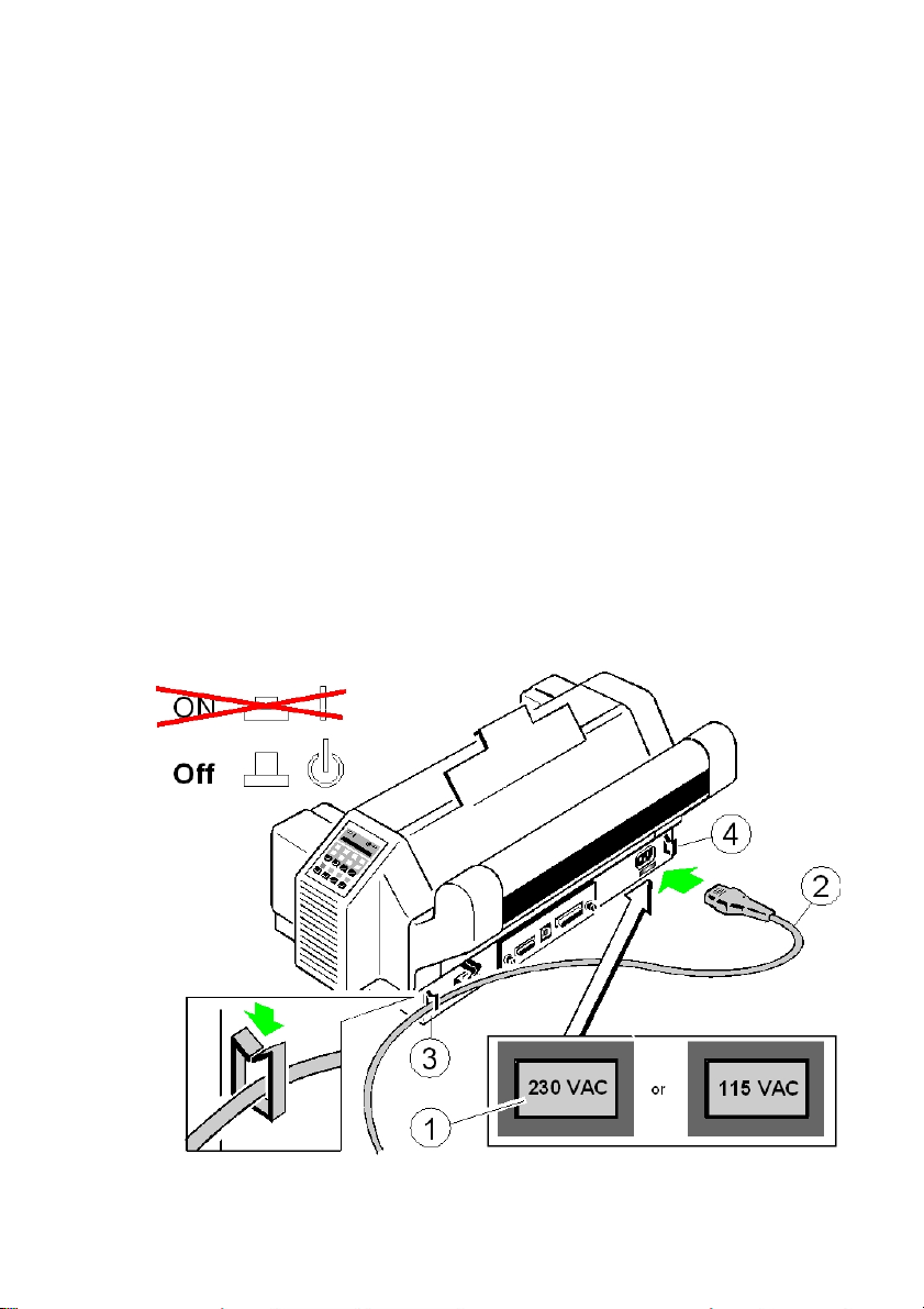
1.6 The Power Supply
Mains Voltage
In general, the main's voltage selection is determined at factory sites.
Make sure that the specified voltage on the label (1) corresponds to your main's
voltage:
S The 230 V setting applies to the range of 180 to 264 V alternating current.
Note: Since an incorrect voltage selection can seriously damage the printer,
please pay special attention to the following.
Connect the printer to the mains using the power cord (2). First connect the
cable to the power cord socket and then to the mains. Fasten the Power cord
depending upon position of the mains, into the clip (3) or (4).
Note: As the power cord serves as a safety cut off, its connection to the printer
must be accessible any time.

Getting Started
1-10
1.7 Power ON/OFF Switch
The power ON/OFF switch (1) turns the printer's power supply ON or OFF.
After switched ON the printer an internal self-test which checks the electronics,
the print head carriage movement and the interface will be performed.
At first the yellow LED on the Operator Panel is lighting up and the display
shows TEST.....0.1 (bootstrap). In the next step the yellow LED will be dark, the
green LED lights up and the display shows TEST....FW..0101234 (version of the
firmware).
If the message INSTALL RIBBON is shown, follow the steps in paragraph 1.8
Installing the Ribbon Cassette.
After inserting the ribbon press to continue. When the internal test has been
completed successfully the display shows READY 1 ELQ or BUSY 1 ELQ in
case data has already been transmitted.
Note: If the display shows anything different please refer to chapter
4 Troubleshooting and Diagnostics.

Getting Started
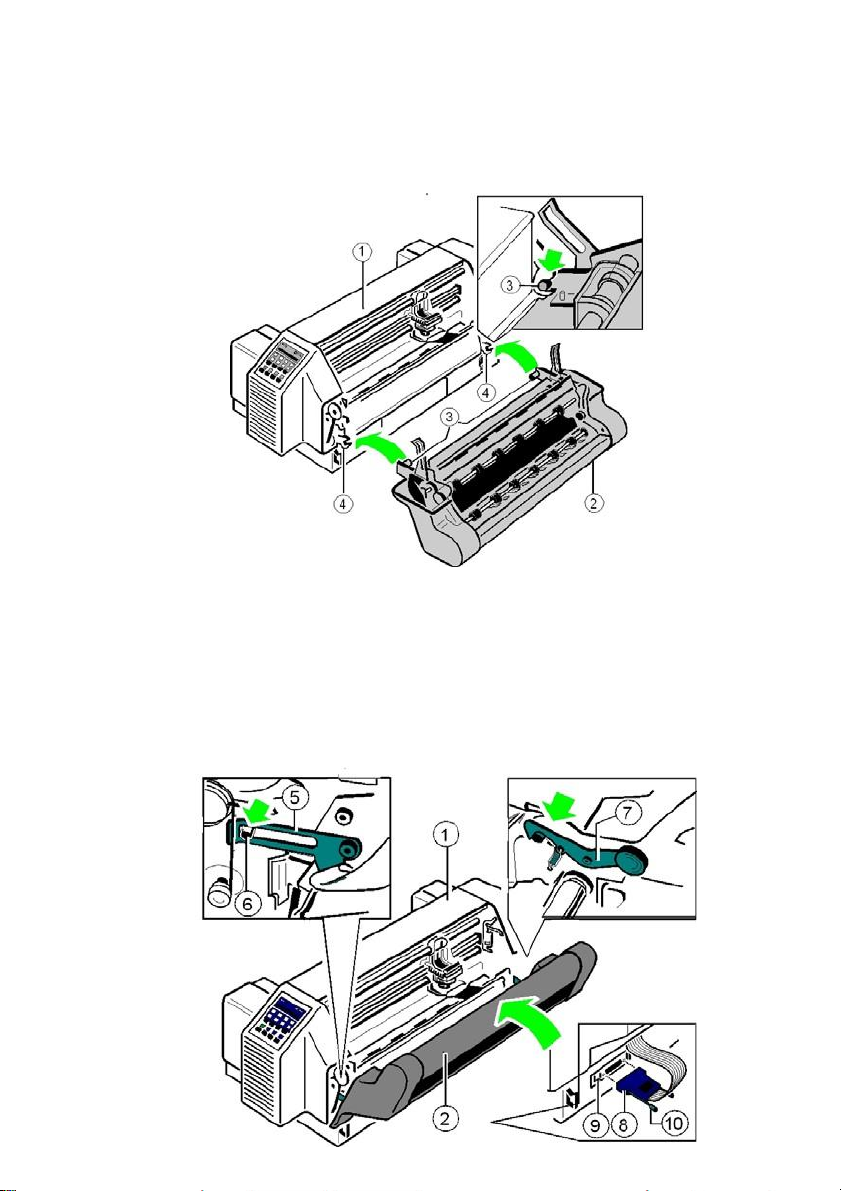
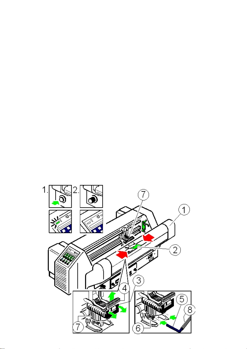
1.8 Installing the Ribbon Cassette
It is recommended to use only original ribbon puts out by our company. Using
other ribbons will void your warranty.
Caution: Never manually move the print head fully to the right-hand stop (you
could change the way of the paper output).
Note: If the printer is busy (message BUSY 1 ELQ) always press before
opening the top cover.
1.
Switch the printer ON at the power switch; Power LED is lit and waits for the
message READY 1 ELQ or INSTALL RIBBON.
2.
If the printer is busy (message BUSY 1 ELQ) press .
3.
Lift the top cover to gain access to the ribbon cassette mountings. The print
head will move to the correct position, aligned with the cut out in the paper
guide plate to facilitate the installation of the ribbon cassette.
4.
Remove any excess slack by turning the green knob (6) on the ribbon
cassette clockwise. Move the ribbon feed guide (7) to the position indicated on
the plastic housing of the cassette.
1-11

Getting Started
1-12
5.
Position the ribbon feed guide (7) between the print head (4) and the green
plastic plate (8).
Continuation next page.

Getting Started
1-13
6.
Fit the upper mounting pins (9) into the green mounting brackets (10) and
gently move the cassette toward you until you hear a click on both sides.
Swing the ribbon underneath the print head (4) until the lower mounting
pins (11) also engage with a click on both sides. The audible clicks indicate
that the mounting pins have engaged properly.
Note: At each end of the ribbon cassette there are two pins (9) and (11) which
keep the cassette in position when mounted. When installed correctly the
ribbon cassette is not parallel to the printer's housing (12).
7.
Move the print head (4) back and forth to settle the ribbon in the correct
position.
8.
If necessary remove excess ribbon slack by turning the green knob (6)
clockwise.
9.
Close the top cover (3) and press .

Getting Started
1-14
1.8.1 Replacing the Ribbon Cassette
Caution: The print head may be very hot immediately after printing!
1.
Close the top cover and power on the Printer. After the display shows
READY 1 ELQ, open the top cover. The print head (4) will move to the
correct position, aligned with the cut-out in the paper guide plate (5) to
facilitate the installation of the ribbon cassette.
2.
Now swivel the lower part of the ribbon cassette to the rear.
In this way the mounting pins (11) loosen from the lower position.
3.
Then press the upper part of the ribbon cassette also to the rear. The upper
mounting pins (9) get free and the ribbon cassette can be taken out.
4.
To install a new ribbon cassette please see 1.8 Installing the Ribbon
Cassette.

Getting Started
1-15
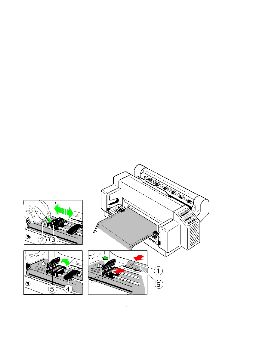
1.9 Inserting Fanfold Paper
The printer has two tractor cassettes (1) for fanfold paper. They are named
TRACTOR LOWER and TRACTOR UPPER. The standard setting of the paper
source is the TRACTOR LOWER cassette.
Ensure that the printer is placed in the depression on the top of the stand
(option). If the printer is used without a stand, align the printer with the front edge
of the table. The cables at the back of the printer should be tucked into the cable
clips in order not to block the paper path (see section 1.6 The Power Supply).
Handling of the Tractor Cassettes
Simply slide the tractor cassettes forward into the respective guides until you
hear a click (see illustration). Remove the tractor cassettes by lifting and pulling
them toward you. Take out the TRACTOR UPPER before inserting paper into
the TRACTOR LOWER. If more than two different fanfold papers are to be
processed, it is useful to work with additional tractor cassettes. They can be
loaded with paper in advance and just need to be plugged into the printer as
required.
Getting Started
1-16
Insert the paper as shown in the illustration; the top edge of the paper must be
equal with the top of the tractors or maximum up to two transport holes above
the tractors. The left perforation should be aligned with the centre mark (1) on
the plastic plate (6).
Paper without vertical perforation should be aligned in such a way that the left
holes are positioned to the left of the centre mark (1) on the plastic plate (6).
Inserting paper for the first time or changing to another paper width:
1.
Push the green tractor lock levers (2) to the rear to release both tractors (3).
2.
Roughly adjust both tractors (3) to the paper width, and space out the paper
supports (4) evenly.
3.
Open the tractor covers (5) and insert the paper in such a way that the top
edge partly covers the plastic plate (6).
4.
Close the tractor covers (5) and move both tractors with the paper until the left
perforation is aligned with the centre mark (1) on the plastic plate (6).
5.
Both green locking levers (2) put forward, in order to lock the tractors (3).
Note: The pins of the tractors (3) must be centred in the transport punches of the
paper!
Getting Started
1-17
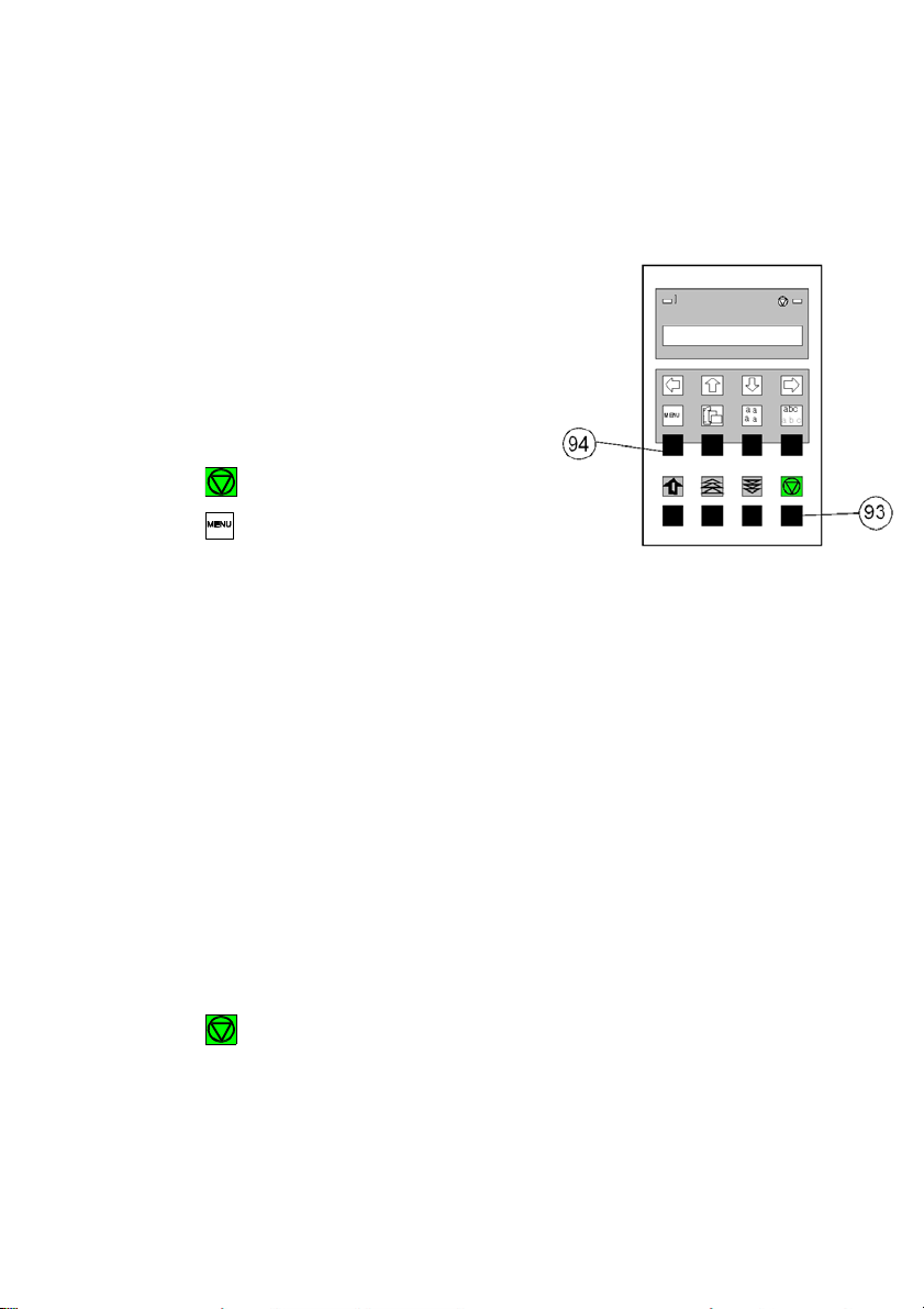
1.
Taste
Switch the printer on.
Anzeige
2.
(93)
LOCAL
3.
(94)
MACRO SELECT
6
4.
[\] -- [\]
INSTALLATION
6
5.
[Y] 7 INTERFACE
6 6.
[\] -- [\]
7 LANGUAGE
6
7.
[Y] 7 ENGLISH
w
8.
[\] 7 DEUTSCH
9.
[Y] 7 DEUTSCH
w
10.
[Z] 7 SPRACHE
6
1.10 Selection of Operator Panel Language
The printer control panel and LCD display menu is used for the next steps. It is
possible to change the language in the printer menu from English to French or
German. The following example shows how to change from English to German:
11.
12.
13.
14. (93) BEREIT 1 ELQ
Note: You find a description of the function keys in chapter 2 Printer Operation.
[Z] INSTALLATION 6
[\] MENÜ SICHERN 6
[Y] 7 SICHERT 6
MENÜ SICHERN 6
Getting Started
1-18
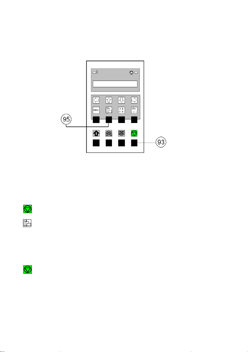
2. (93) LOCAL
3. (95)
7 TRACTOR LOWER *
4. [\]
5. [Y]
7 TRACTOR UPPER
7 TRACTOR UPPER *
6. (93) READY 1 ELQ
1.11 Paper Source Selection
The TRACTOR LOWER is the default paper source. Using the control panel to
change to the TRACTOR UPPER is explained below:
Key Display
1. Switch the printer on.
Note: If fanfold paper is already being printed while changing the paper source it
will be depending on the printer type offered for tear off ore moved forward,
cut, and moved to the park position. In this case are four transport holes
above the tractors are visible.

Getting Started
1-19
1.12 Test Prints
There are three test prints available.
S PRINT TEST 1 shows a pattern of all printable characters. Use this to check if
the printer operates correctly.
S PRINT TEST 2 produces a standard letter (ECMA-132) which can be used for
measuring the printer's throughput.
S PRINT TEST 3 lists all available fonts, contains the page count to identify the
actual number of printed pages, and gives information on technical releases
which are intended for service purposes.
The print tests are printed using the parameters set in the menu, e.g. font, pitch
etc. Refer to Appendix A Configuring the Printer for details.
ABCDEFGHIJKLMNOPQRSTUVWXYZabcdefghijklmnopqrstuvwxyz0123456789!§
§ABCDEFGHIJKLMNOPQRSTUVWXYZabcdefghijklmnopqrstuvwxyz0123456789!
!§ABCDEFGHIJKLMNOPQRSTUVWXYZabcdefghijklmnopqrstuvwxyz0123456789
9!§ABCDEFGHIJKLMNOPQRSTUVWXYZabcdefghijklmnopqrstuvwxyz012345678
89!§ABCDEFGHIJKLMNOPQRSTUVWXYZabcdefghijklmnopqrstuvwxyz01234567
789!§ABCDEFGHIJKLMNOPQRSTUVWXYZabcdefghijklmnopqrstuvwxyz0123456
6789!§ABCDEFGHIJKLMNOPQRSTUVWXYZabcdefghijklmnopqrstuvwxyz012345
56789!§ABCDEFGHIJKLMNOPQRSTUVWXYZabcdefghijklmnopqrstuvwxyz01234
456789!§ABCDEFGHIJKLMNOPQRSTUVWXYZabcdefghijklmnopqrstuvwxyz0123
3456789!§ABCDEFGHIJKLMNOPQRSTUVWXYZabcdefghijklmnopqrstuvwxyz012
23456789!§ABCDEFGHIJKLMNOPQRSTUVWXYZabcdefghijklmnopqrstuvwxyz01
123456789!§ABCDEFGHIJKLMNOPQRSTUVWXYZabcdefghijklmnopqrstuvwxyz0
0123456789!§ABCDEFGHIJKLMNOPQRSTUVWXYZabcdefghijklmnopqrstuvwxyz
z0123456789!§ABCDEFGHIJKLMNOPQRSTUVWXYZabcdefghijklmnopqrstuvwxy
yz0123456789!§ABCDEFGHIJKLMNOPQRSTUVWXYZabcdefghijklmnopqrstuvwx
xyz0123456789!§ABCDEFGHIJKLMNOPQRSTUVWXYZabcdefghijklmnopqrstuvw
wxyz0123456789!§ABCDEFGHIJKLMNOPQRSTUVWXYZabcdefghijklmnopqrstuv
vwxyz0123456789!§ABCDEFGHIJKLMNOPQRSTUVWXYZabcdefghijklmnopqrstu
uvwxyz0123456789!§ABCDEFGHIJKLMNOPQRSTUVWXYZabcdefghijklmnopqrst
tuvwxyz0123456789!§ABCDEFGHIJKLMNOPQRSTUVWXYZabcdefghijklmnopqrs
stuvwxyz0123456789!§ABCDEFGHIJKLMNOPQRSTUVWXYZabcdefghijklmnopqr
rstuvwxyz0123456789!§ABCDEFGHIJKLMNOPQRSTUVWXYZabcdefghijklmnopq
qrstuvwxyz0123456789!§ABCDEFGHIJKLMNOPQRSTUVWXYZabcdefghijklmnop
pqrstuvwxyz0123456789!§ABCDEFGHIJKLMNOPQRSTUVWXYZabcdefghijklmno
opqrstuvwxyz0123456789!§ABCDEFGHIJKLMNOPQRSTUVWXYZabcdefghijklmn
nopqrstuvwxyz0123456789!§ABCDEFGHIJKLMNOPQRSTUVWXYZabcdefghijklm
mnopqrstuvwxyz0123456789!§ABCDEFGHIJKLMNOPQRSTUVWXYZabcdefghijkl
lmnopqrstuvwxyz0123456789!§ABCDEFGHIJKLMNOPQRSTUVWXYZabcdefghijk
klmnopqrstuvwxyz0123456789!§ABCDEFGHIJKLMNOPQRSTUVWXYZabcdefghij
jklmnopqrstuvwxyz0123456789!§ABCDEFGHIJKLMNOPQRSTUVWXYZabcdefghi
ijklmnopqrstuvwxyz0123456789!§ABCDEFGHIJKLMNOPQRSTUVWXYZabcdefgh
hijklmnopqrstuvwxyz0123456789!§ABCDEFGHIJKLMNOPQRSTUVWXYZabcdefg
ghijklmnopqrstuvwxyz0123456789!§ABCDEFGHIJKLMNOPQRSTUVWXYZabcdef
fghijklmnopqrstuvwxyz0123456789!§ABCDEFGHIJKLMNOPQRSTUVWXYZabcde
efghijklmnopqrstuvwxyz0123456789!§ABCDEFGHIJKLMNOPQRSTUVWXYZabcd
defghijklmnopqrstuvwxyz0123456789!§ABCDEFGHIJKLMNOPQRSTUVWXYZabc
cdefghijklmnopqrstuvwxyz0123456789!§ABCDEFGHIJKLMNOPQRSTUVWXYZab
bcdefghijklmnopqrstuvwxyz0123456789!§ABCDEFGHIJKLMNOPQRSTUVWXYZa
abcdefghijklmnopqrstuvwxyz0123456789!§ABCDEFGHIJKLMNOPQRSTUVWXYZ
PRINT TEST 1

Getting Started
1-20
Eilzustellung
Norddeutsche Farbwerke KG
Herrn Dr. Grauert
Große Elbstraße 64
2000 Hamburg 4
Org. III 5/37 H-A 4 43 22.04.75
17.04.75 Volkmann
Vordruckgestaltung für den allgemeinen Schriftverkehr, für das Bestell- und Rechnungswesen E i l t
Sehr geehrter Herr Dr. Grauert,
Sie können das Schreiben der Briefe, Bestellungen, Rechnungen usw.
sowie das Bearbeiten des Schriftguts rationalisieren, wenn die
Vordrucke Ihres Unternehmens den folgenden Normen entsprechen:
DIN 676 Geschäftsbrief; Vordrucke A4
DIN 677 -; Vordruck A5
DIN 679 Geschäftspostkarte; Vordrucke A6
DIN 4991 Vordrucke im Lieferantenverkehr; Rechnung
DIN 4992 -; Bestellung (Auftrag)
DIN 4993 -; Bestellungsannahme (Auftragsbestätigung)
DIN 4994 -; Lieferschein/Lieferanzeige
DIN 4998 Entwurfsblätter für Vordrucke
Diese Normen enthalten alle Einzelheiten für den sinnvollen und
zweckmäßigen Aufdruck. Wenn dazu bei der Beschriftung genormter
Vordrucke DIN 5008 'Regel für Maschinenschreiben' beachtet wird,
entstehen übersichtliche und werbewirksame Schriftstücke.
Die beifgefügten 6 Mustervordrucke zeigen, daß das Beachten der
Normen die künstlerische und werbewirksame Gestaltung der Vordrucke nicht ausschließt.
Da wir uns auf die Herstellung genormter Vordrucke spezialisiert
haben, können wir besonders billig liefern. Eine Probestellung
wird Sie und Ihre Geschäftsfreunde von den Vorteilen überzeugen.
Mit bester Empfehlung
NORAG
Druckerei und Verlagshaus KG
Herrmann
Anlagen
6 Mustervordrucke
PRINT TEST 2

Getting Started
1-21
2.
KEY
(93)
Display
LOCAL
3.
(94)
MACRO SELECT
6
4.
[\] -- [\] INSTALLATION
6 5.
[Y] 7 INTERFACE
6
6.
[[] -- [[] 7 SELF TEST
6
7.
[Y] 7 PRINT TEST 1
Use
8.
[\] to select PRINT
[Y]
TEST 2 or 3.
7 PRINT TEST 1
w
9.
(93)
PRINT TEST 1
w
1.
(93) 7 PRINT TEST 1
w
2.
[Z]
7 SELF TEST
6
3. (93)
READY
1 ELQ
To start a print test:
1. Switch the printer ON (display shows READY 1 ELQ).
The following identifies the keys to press and the corresponding operator panel
messages.
The printer starts to print using paper from the defined paper source.
To stop the print test:

Getting Started
1-22
1.13 Connection to a Computer
Parallel, Serial, or USB Interface.
S Switch the printer and computer OFF.
S Connect the interface cable coming from the computer to the printer's
parallel (1), serial (2), or USB port (3).
S The printer is set by default to SHARED (PARALLEL/RS232) interface with
the following parameters:
S 8 Kbyte buffer
S 8 bit
S 9600 baud
S parity ignore
S DTR protocol.
SHARED means that, after Power-ON, both the serial and the parallel interfaces
are available for data transfer. The port to which data is sent becomes active
automatically.
If the parallel, serial, or USB parameters need to be changed, see Appendix A
Configure the Printer and Appendix B Interface Description.


1-24
2.
MACRO 2
6
3. [Y]
READY
2 IPP
1.14 Emulation Selection
The following emulations are included in the PM Ser/Par/USB:
S EPSON LQ / ESC/P2 in Macro 1
S IBM Proprinter XL 24 in Macro 2
S IBM Proprinter XL 24 AGM in Macro 3
S EPSON LQ / ESC/P2 in Macro 4
The factory setting is the EPSON LQ/ESC/P2 emulation in Macro 1.
To change from one emulation to another, follow the procedure below. The
example shows the keys to press along with the display information for a change
from EPSON LQ in macro 1 to IBM PROPR. in macro 2
1.
Switch the printer ON. The display shows READY 1 ELQ.
The information READY 2 IPP indicates the selected macro and the emulation
of this macro, for example:
1 ELQ Macro 1 with Epson LQ / ESC/P2 Emulation
2 IPP Macro 2 with IBM Proprinter Emulation
3 AGM Macro 3 with IBM Proprinter AGM Emulation
4 ELQ Macro 4 with Epson LQ / ESC/P2 Emulation.
Note: A number of parameter settings (Print Quality, Page Length, Margin,
or Paper Source) is summarized in a "Macro". It is possible to have a
total of four macros, each with a different summary of parameter
settings.
2-1
2. Printer Operation
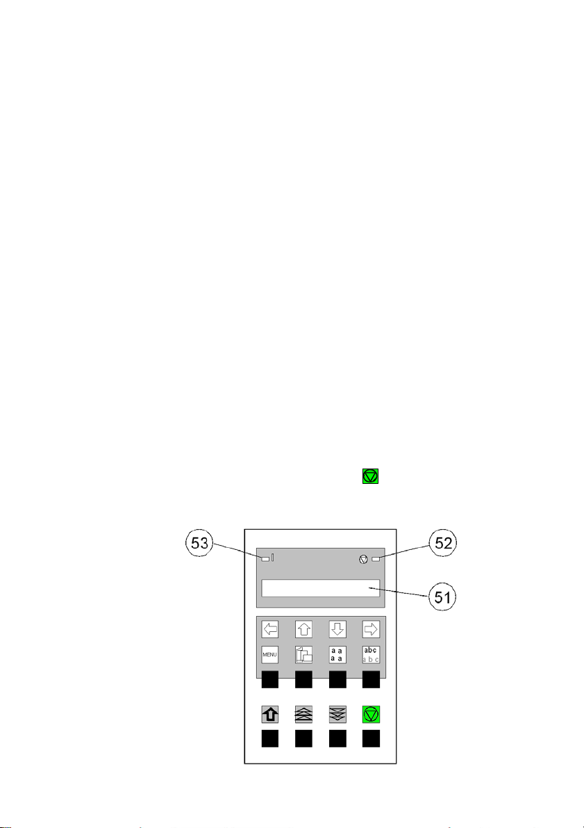
2.1 Control Panel
The control panel
S controls the set-up for communication with the host computer
S controls various parameter settings
S allows manual control of the paper handling
S gives information about the printer's status.
The 16-character Liquid Crystal Display (LCD) (51) indicates the current
status of the printer. If an error occurs (e.g. COVER OPEN), the resulting error
message overrides any other displayed message. When the error condition not
longer exists, the original status information appears on the display.
The green Power ON indicator (53) is lit when the printer is supplied with
power by setting the power ON/OFF switch to ON.
The yellow STOP indicator (52) is lit when the printer is in the STOP mode.
The printer enters the STOP mode either when (93) is pressed or when an
error condition occurs such as NO PAPER, COVER OPEN, etc.

Printer Operation
2-2
Number
Symbol
Functionality in ONLINE/READY Mode
90
Quick VERT.POS.ADJ. setting entry
91
FANFOLD DISPLACEMENT mode entry
92 No function
93
[START/STOP] key - after pressing the key, the
printer enters the LOCAL mode.
94-97
MACRO SELECTION to enter the quick macro
selection mode.
Number
90
Symbol
Functionality in LOCAL Mode
EJECT FORM
91, 92
Paper movement up and down
93
START/STOP key - after pressing the
[START/STOP] key, the printer enters the READY
or BUSY mode.
94
MENU key - to enter the Menu Mode in the first
level.
95
PAPER SOURCE key - to start the paper source
selection.
96
FONT key - to start the font selection.
97
PITCH key - to start the pitch selection or to
confirm a certain set up, or to confirm the quick
macro selection.
2.2 Function Keys
The function keys of the operator panel are grouped into two rows. The function
of a key depends on the printer operation state. Following operation states are
possible:
S READY or BUSY
S LOCAL
2.2.1 Short Description of Keys
– in the printer operation state READY or BUSY
Note: It is possible to lock the function of the above described keys in the
printer operation state READY or BUSY. Use the menu function
MENU ACCESS with the setting QUICK SET OFF (see Appendix A
Configuring the Printer). If the keys are locked, the printer shortly
displays LOCKED when pressing one of the keys.
It is not possible to lock the [START/STOP] key .
– in the printer operation state LOCAL

Printer Operation
2-3
Note: After pressing one of the keys the menu mode is
activated. Now the keys of the top row can only be used as cursor
keys to move within the menu tree (right [Y], left [Z], up [[] and down
[\]).
2.2.2 Detail Description of Keys
S in the printer operation state READY or BUSY
S Quick Settings (only active if not locked in the menu function
MENU ACCESS with QUICK SET OFF (see Appendix A)).

Printer Operation
4-2
S Top Row Keys
The Quick Macro Selection mode is entered when one of the top row keys
, , , or is pressed. From the left to the right macro 1 to macro 4
will be selected. Pressing of key causes the printer to change in the
STOP-mode and in the display appears the message MACRO 2. Pressing
key [Y] confirms the macro selection and changes the printer into the READY
or BUSY mode. After this sample the printer the message on the display is
READY 2 IPP. That means macro 2 with IBM ProPrinter emulation is
selected.
If you press one of the above described key erroneously, press for
correction.
Note: Macro selection means a change of all configuration parameters of the
macro concerned.
S Lower Row Keys
In case a certain application requires a specific vertical positioning of the
printout on a continuous form, two possibilities are provided for the READY or
BUSY mode:
S vertical position adjustment VERT.POS.ADJ. with key (90)
S fanfold displacement FANFOLD DIS with key (91).
S Vertical Position Adjustment (VERT.POS.ADJ.) (90)
This can be set differently for each macro to exactly position the printout in
relation to the top edge of the form in use. Using this function, the TOP
MARGIN and BOTTOM MARGIN settings are taken into account as well.
The parameter is part of the printer's configuration set up memory and can
be stored with the SAVE function.
The VERT. POS.ADJ. mode can directly be called up in the status READY
or BUSY by pressing key . In this case a set up is possible for the
actually paper source of the selected macro. With TRACT. L. V or
TRACT. U. V the printer asks for the value of the lower or upper tractor.

Printer Operation
2-5
60
60
Key
Display
1 READY
1 ELQ
2 FANFOLD DIS
0
3 FANFOLD DIS
0, +1, +2, +3...
4 FANFOLD DIS
....+3, +2,+ 1, 0
5 READY
1 ELQ
This parameter covers a range of -15/ to +
240
/ of an inch (0.42 mm),
where "-" is up the page and "+" is further down the page (see also the
table in Appendix A Configuring the Printer for VERT.POS.ADJ.).
Note: The set up of VERT.POS.ADJ. will become effective at the next page of
the form. Therefore, it is recommended to perform VERT.POS.ADJ. set up
as long as the paper is in the park position and before starting the print job.
S Fanfold Displacement (FANFOLD DIS) (91)
A continuous form can manually be displaced by this function when it is
either correctly loaded at the park position or already fed and partly printed.
The Fanfold Displacement mode can only be called up in the status
READY or BUSY.
Note: The key has no effect when in the READY or BUSY mode.
As soon as the Fanfold Displacement mode is entered by pressing ,
the printer stops printing and changes into the LOCAL mode. The display
shows the message FANFOLD DIS with the value 0. By pressing (91)
or (92) a vertical displacement is possible.
Note: This parameter influences the line counter of the current print job and
cannot be saved. A form feed (FF) sent by the application to the printer
cancels all these settings.

Printer Operation
6-2
60
60
( /
6
How to Use this Function
Preprinted paper (e.g. bill of lading) has to be adjusted exactly. Following
errors are possible:
S the printed value is too high - the fanfold paper has to be moved a little
bit higher.
S the printed value is too low - the fanfold paper has to be moved a little
bit lower. No backward movement is possible for a form in park position
or with the print head on the first line. The displacement will become
effective on the next page. A negative displacement is possible if this
function is used during a current print job (not at the beginning of the
page).
After pressing again, paper is fed in case it was in the park position. In
all other cases the paper remains at its actual position. Each further
pressing of increases the line counter by increments of 1/
further pressing of decreases the line counter by decrements of 1/
inch. Holding of or causes the first 20 increments in single steps
1
inch), thereafter in multiplier of ten which results in a continuous
60
inch. Each
increment or decrement of the offset counter by 1/
inch. If the reached
value is too high go backwards by pressing .
The offset to the current position is shown on the display. Dependent on
the status of the internal print buffer, the offset will be immediately
executed after having resumed the printing or after having printed the
remaining data in the internal print buffer. The offset value is not stored in
the configuration set up and influences only the actual line counter. The
maximum displacement range is the distance between the actual position
and the page border plus one full page, but no more than 999 steps (nearly
1 inch). A backward movement is possible from the actual position to the
top of that page.
If the setting is procedure is completed change with (93) to the
READY or BUSY mode.

Printer Operation
2-7
There are two possibilities for the displacement to become active:
S If a positive displacement is set before starting the print job the printer
will move the paper into the right position first and then start printing.
S If the displacement is set during a print job, the printer prints the
contents of the print buffer. Afterwards, the displacement will become
active. All following data are at the new position.
S Pressing [START/STOP] (93)
The printer changes into the LOCAL mode (displayed) and turns on the
STOP indicator (52). All printer and paper handling operations are
stopped. After pressing again, the printer quits the LOCAL or Menu
mode.
2.2.3 Meaning of the Lower Row Keys in the LOCAL Mode
S Insert or Eject Key (90)
After pressing the Insert/Eject key, fanfold paper from the park position
is fed into the print position, and fanfold paper from the print position is
fed into the cut/tear off position (depending on the setting or the printer
type). Paper that has been retracted into the cut/tear off by the
Insert/Eject key will be moved automatically into the print position once
the printer receives a print command.
Note: This key is not active while the top cover is open.
S The Paper Feed Key (91) and the
Reverse Paper Feed Key (92)
The paper moves 1/ 90" (0.28 mm) in the direction of the arrows. Holding
down the key results in continuous feeding.
Forward movement of paper from the park position is stopped at the
print position. Forward movement of paper from the print position is
stopped at the tear off position or it will be cut off (depending of the
setting or of the printer type).
Backward movement of paper is stopped at either the park position, the
print position or the tear off position.

Printer Operation
8-2
S START/STOP Key (93)
S turns off the STOP indicator
S makes the printer ready for operation
S either starts the printout or self-test functions when selected (see
MENU mode) or causes the interface status to change to READY or
BUSY (displayed)
S exits the MENU mode.
2.3 Menu Mode
All operator's selectable features are access able via the control panel and
combined in the printer MENU
This feature provides:
S easy handling of configuration (interface, etc.)
S quick parameter changes during an application
S a SAVE function to make changes permanent (until purposely reset),
facilitating changes in default settings.
The menu has several levels:
S The first level contains the Main Functions
S Level 2 contains Sub-Functions
S Level 3 allows to select/confirm values and contains further Sub-Functions
S Level 4 allows to select/confirm values
For easy selection of paper source, font, pitch and macro, please refer to the
Quick Settings section in this chapter.
Printer Operation
2-9
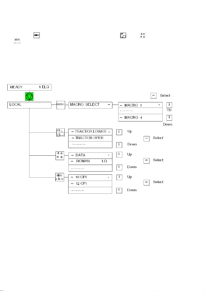
2.3.1 To Activate the Menu:
S Press (93)
The printer is in the STOP mode, the display shows LOCAL
S Press (94) in the top row of the control panel. As soon as the menu
mode has been activated, the keys in the top row can only be used as cursor
keys to move within the menu tree (up, down, right, and left).
Selection within a level:
S press [[] or [\] key; the keys have a wrap around function, i.e. after the last
value the first value is repeated.
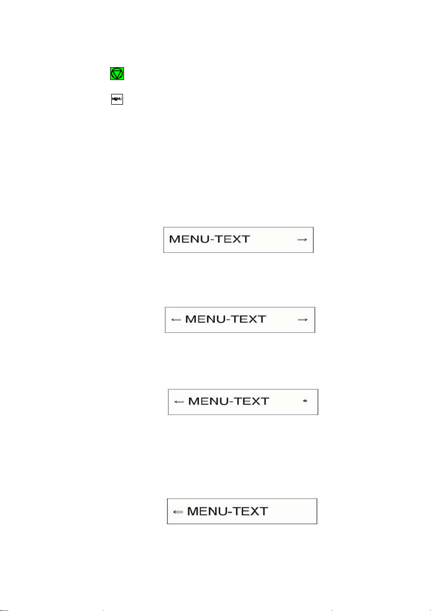
On the display you will find the following four characteristic types of information:
This display is only shown if you are in the Main Function. To switch to the next
level press [Y].
Now you are in a Sub-Function. Movement in both directions is possible by
using the [Z] key or [Y] key.
In the last level, labelled select/confirm values, the asterisk
indicates the actual selection.
(’)
to the right
By using the [[] or [\] key, you are able to select a ne w value. You get the
display:

Printer Operation
2-10
2.3.2 To Confirm Selection:
- press [Y]; the confirmed value is displayed with an asterisk
position as shown in the picture before.
(’)
in the last
Note: All cursor keys have an auto repeat function.
The new confirmed settings are only valid until the printer is powered
off. To save your settings permanently, see next section.
The MENU mode is left either by pressing or by moving to the MAIN
FUNCTION level and then pressing the [Z] key.
A number of VALUE settings is summarized in a "Macro". It is possible to have a
total of four macros, each with a different summary of VALUE settings. The
standard macros have the following emulations defined:
Macro Emulation
1 EPSON LQ 1060, LQ 2550 / ESC/P2
2 IBM Proprinter XL 24
3 IBM Proprinter XL 24 AGM
4 EPSON LQ 1060, LQ 2550 /ESC/P2
Macro parameters can be tailored to specific application requirements. This
feature is highly beneficial in case of frequent changes between applications in
multi-user environment. Instead of having to adjust the menu settings each time
before a particular application is starting, the user simply selects the macro
containing the pre-defined set-up configurations.

Printer Operation
2-
2.3.3 How to Save Settings
The settings selected and confirmed are only active until the printer is switched
off. In order to prevent losing your new settings you can save them using the
MAIN FUNCTION SAVE.
KEY Display
1.
2.
(93) LOCAL
(94) MACRO SELECT 6
3. [[] -- [[] SAVE
4.
[Y] SAVING NOW
4a. SAVE 6
5.
Note: The values of the "current settings" and the macro settings can be printed
(93) READY 1 ELQ
out on a list using the function PRINT OUT.
6
(display is flashing)
’
Printer Operation
2-12
2.3.4
Quick Settings
The keys
(94) (to select a pre-configured macro),
(95),
(96), and
(97) are shortcuts in the menu tree. These particular selections can be
changed quickly without having to move through the entire menu (see fold out of
structure diagram). As soon as one of the keys in the top row has been
activated, all four keys can only be used as cursor keys to move within the menu
tree ([[] up, [\] down, [Y] right, and [Z] left).

3-1
3. Maintenance
Preferred Materials
The following materials and cleaning lubricants are recommended for use in the
maintenance procedure:
S Lint-free cloth
S Vacuum cleaner.
3.1 Cleaning
The user should clean the printer every six months or after 50,000 prints,
whichever occurs first. If you experience paper feed problems, or if the print
head carriage movement becomes affected, cleaning should be carried out
more often.
Note: the Page Counter (PGCNT) in the PRINT-TEST 3 will give you
information about actual number of printed pages. (See sample next
page.)

Maintenance
3-2
FW
20111234
F-D
0.2
F-X
0.3
SN
01001234
NFQ
2100
DSF
100
NLSF
100
LSF
100
GSF 80
NTF
230
TNA1
230
TNA2
260
TNA3
260
CAC
5.00
PSL
44
PGC
42
PGCNT
333
SBP
25
C031 ISO 8859/1
C035 ISO 8859/9
C063 IBM CODE PAGE
C101 CODE PAGES EE2
C032 ISO 8859/15 C061
IBM SET 1 C071 EPSON
EXT. GCT C069 ALL ICT
TABLE
C034 ISO 8859/5 C062 IBM
SET 2 C100 CODE PAGES EE
C091 BARCODE
DATA ROMAN
NLQ
ROMAN
LQ
SAN SERIF
NLQ
SAN SERIF
LQ
COURIER
NLQ
COURIER
LQ
PRESTIGE
NLQ
PRESTIGE
LQ
SCRIPT
NLQ
SCRIPT
LQ
OCR B
LQ
OCR A
LQ
ORATOR-C
NLQ
ORATOR-C
LQ
ORATOR
NLQ
ORATOR
LQ
DATA LARGE
PRINT TEST 3
CONFIGURATION
CHARACTER SET : EPSON EXT. GCT 3: GERMANY
AGC TEST AGC TEST AGC TEST AGC TEST AGC TEST
PRINTHEAD NEEDLE
1 2 3 4 5 6 7 8 9 10 11 12 13 14 15 16 17 18 19 20 21 22 23 24
DATA
§ !"#$%&'()*+,-./01234567890:;<=>?.......
.
.
Note: The number behind FW indicates the firmware and the number behind SN
the serial number of the interface (PM).

Maintenance
3-3
3.2 Cleaning Procedure
1.
Power the printer ON and remove the top cover.
2.
Remove the ribbon cassette.
3.
Thoroughly brush and vacuum all accessible areas to remove any paper flock
and dust.
4.
Clean the platen's surface, the paper pressure rollers and the transport rollers
using the platen cleaner. In order to access the transport rollers loosen the
green screws and remove the metal bar with the metal rollers.
5.
Clean the covers and the operator panel with a damp, lint-free cloth. Do not use
cleaning solvents or excessive amounts of water.
6.
Insert the ribbon cassette (see Chapter 1.8 Installing the Ribbon Cassette).
7.
Remount the top cover.
Note: Cutting through a sticky label leaves glue on the blade, leading to problems
with the cutting device. Small parts of a cut through label could detach from
its paper and get stuck under the shield of the print head or even block the
cutter completely. If the shield or the blade gets dirty it must be cleaned
immediately. Use a close with petrol.
Caution: There is danger to get hurting.
Maintenance
3-4
3.3 User Replaceable Parts
Replacement of the Print Head
The print head has an expected life time of approximately 350,000 pages (see
Page Counter (PGCNT in PRINT TEST 3).
S Print Head Removal
Caution: The print head may be very hot immediately after printing.
1.
Switch the printer ON, lift and remove the top cover. The print head will move
to the correct position, aligned with the cut-out in the green paper guide plate
(2).
2.
Remove the ribbon cassette.
3.
Switch the printer OFF.
4.
Swivel the Cutter Unit (1) to the rear (only in the case of the High Speed
Fanfold Printer with cutter).
5.
Press the black plastic hooks (3) for the attachment of the plug (4) toward the
arrows. Seize the plug (4) on both short sides and disconnect the print head
cable.
6.
Using the supplied tool (5)., loosen the two captive screws (6) retaining the
print head (7). Use the enclosed plastic case (8) as an extension for the allen
key.
7.
Remove the print head (7).

Maintenance
3-5
S Print Head Installation
Ensure that the printer is switched OFF. For print head installation, the carriage
should be aligned with the cut-out in the paper guide plate (same position as for
removal procedure).
1.
Hold the print head (1) in its mounting position and press it against its stop in
direction of the platen. The two noses (2) of the adjustment guide (3) support
this procedure.
2.
Fasten the captive screws (4):
S fasten the right screw to its stop
S tighten the left screw
S now tighten the right screw
S put the enclosed plastic case (5) onto the allen key (6) and first tighten the
right and then the left screw.
3.
Connect the plug (7) with the print head cable and lock in position the black
plastic hooks (8).
4.
Close the Cutter Unit (9) (only in the case of the High Speed Fanfold
Printer with cutter).
5.
Mount and close the top cover.
6.
Switch the printer ON, open the top cover after the message READY 1 ELQ
and insert the ribbon cassette.
7.
Run the MENU function AGC ADJUST with ribbon cassette installed but
without any paper inserted in the printer.

Maintenance
3-6
3.3.2 Replacement of the Platen
The platen needs to be replaced after approximately 800,000 pages (see Page
Counter (PGCNT) in PRINT TEST 3).
S Remove the Platen (1)
1.
Switch the printer OFF.
2.
Lift and remove the top cover.
3.
Swing back the cutter housing (only in the case of the High Speed Fanfold
Printer with cutter).
4.
Remove the ribbon cassette.
5.
Position the print head to the very right.
6.
Release the green plastic platen clamp (2) on the left platen mounting.
7.
Move the platen (1) approximately 0,4 inch to the left, lift the left end of the
platen free of its mounting and withdraw the platen from the right mounting.
8.
Lift the platen to the left underneath the print head and take it out.


3-8
S Install the Platen
Ensure that the printer is switched OFF.
1.
Place platen (1) in the vacant space between print head and metal bar.
2.
Move print head from its right hand position into the centre.
3.
Fit the gear wheel end of the platen into the right hand side mounting.
Be careful not to damage the gear wheel.
4.
Ensure that the green plastic platen clamp (2) is in the upright position,
push the platen (1) in to its mounting and lock in position by pushing the
tag on the green clamp (2) to the rear.
5.
Install the ribbon cassette.
6.
Close the Cutter Unit (9) (only in the case of the High Speed
Fanfold Printer with cutter).
7.
Mount and close the top cover.
8.
Switch the printer ON, open the top cover after the message READY 1 ELQ
and insert the ribbon cassette.
9.
Run the MENU function AGC ADJUST with ribbon cassette installed but
without any paper inserted in the printer.

4-1
4. Trouble Shooting and Diagnostics
How to Use This Section
1.
Find the category to which your problem belongs. The problem
categories are:
S Power-related Problems
S Error Messages
S No Printout
S Operation-related Problems
S Print-related Problems
S Paper Jam
S Ribbon or Carriage-related Problems
S Diagrams of Error
For example, if the print appears very light on the paper, look at Section Printrelated Problems.
2.
Find the symptom description that most closely matches the printer symptom.
In this example you would look at the symptom "Print faint or of poor
quality”.
3.
Try the first suggestion under that heading.
4.
If the suggestion does not cure the problem, try the next suggestion.
5.
If none of the suggestions enable you to continue printing, or if the fault is not
listed, contact your service office.
Each time the printer is switched ON the display indicates TEST while the
internal self-tests are run. If the test is completed successfully READY 1 ELQ
will be displayed. If an error message is displayed please refer to the following
section.

Trouble Shooting and Diagnostics
4-2
Display
That means...
Cause
No information,
POWER ON indicator not lit.
No power
S Mains cable not connected
S PSU defective
S Correct line voltage
green and yellow
LED give light but
no reaction
hang up in reset
after power on
S Print PSU defective
S Print CU-DEV defective
$$$$$$$$$
Firmware does not
work
S PM not inserted
S PM not correctly inserted
S no firmware on PM
S PROMs not correctly
installed
TEST....
(flashing)
Initializing of the
EEPROM
S After first POWER ON with
PM
S Change of the PM
S Contents of the EEPROM
faulty
4.1 Power-related Problems
S Power indicator does not come On when power is switched On
S Check that the power cord and plug are securely fitted to the printer and to
an electrical outlet.
S Ask for the power connector connections (and fuse, if fitted) to be verified.
S Ask for the building electrical supply to be verified.
4.2 Error Messages
4.2.1 Errors during Selftest
After switching the power ON the printer runs a self test. During the test the
following messages may be shown on the display:

Trouble shooting and Diagnostics
4-3
Display
That means...
Cause
I/O OK
EEPROM located on
the Control Unit not
addressable
EEPROM
S not installed
S not correctly installed
S defective
Display
That means...
Cause / Action
READY 1 ELQ
or
BUSY 1 ELQ
The Printer is OK
S Printer ready for operation
If all tests have been passed successfully the following message will be
displayed:

Trouble Shooting and Diagnostics
4-4
Display
That means...
Cause / Action
LOCAL
Entered in the
OFFLINE mode
when was
pressed. The STOP
indicator is lit.
S Press to continue.
COVER OPEN
Top cover is
opened when
printer is in READY
or BUSY mode
S To continue close the cover
and press .
LOAD TRACTOR L.
or
LOAD TRACTOR U.
Displayed when the
host sends a form
feed or print
command to an
empty tractor
cassette. The
printer enters the
STOP mode.
S Load fanfold into the lower
or upper tractor and
press .
PAPER JAM TRF
Displayed if line
feeds fail to move
fanfold paper
correctly.
S To remove paper jam
please refer to paragraph
4.4 Operation-related
Problems, 4.6 Paper Jam,
and 4.9 Diagrams of
Error for suggestions how
to remove a paper jam.
4.2.2 Errors during Printing
During normal operation the following error messages may occur:

Trouble shooting and Diagnostics
4-5
Display
That means...
Cause / Action
CUTTER ERROR
(only High Speed
Fanfold Printer with
Cutter)
Paper jam in the
Cutter
or
Cutter without any
function
Power off the
printer before
checking!
Open the Cutter Unit and
repair the paper jam (refer to
paragraph 4.6 Paper Jam).
S Cutter not connected
S Connector loose
S Blade locked
S Cutter defective
Find the connector of the
Cutter Unit (look from the
operator panel to the right)
and check the correct fit.
TEAR OFF PAPER
This message is
displayed when the
menu selection is
TEAR OFF and the
printer moved the
paper into the tear
off position.
S Tear off the fanfold paper
and press to enable
the fanfold paper to be fed
backwards to a park
position so that the newly
selected paper source can
be used.
The operator must "tear off"
the fanfold paper along the
tear off edge which is located
directly above the fanfold
paper output (paper should be
torn off from left to right).
Trouble Shooting and Diagnostics
4-6
Display
That means...
Cause / Action
AGC ERROR
AGC ADJUST
procedure fault
S
S
S
S
S
S
Distance print head and
platen faulty
Print head loose
Platen incorrectly installed
Ribbon not inserted
Horizontal drive without
function
Platen got dirty
HOR. DRIVE ERROR
Horizontal drive
S
Horizontal drive blocked
without function
S
Paper jam
S
Distance of platen gap too
narrow
S
AGC procedure on not
workable position
S
Platen incorrectly installed
S
No AGC ADJUST after print
head or platen replacement
S
Device electronic fault
S
Encoder strip missing
S
Horizontal drive fault
PARITY ERROR
Protocol error
S
S
Check protocol setting of
printer and host
Repeat data transfer
BUFFER OVERFLOW
Handshake
protocol error
S
S
Check CTR - CTS or XON -
XOFF protocol
Repeat data transfer
FRAMING ERROR
Protocol error
S
S
Check protocol setting of
printer and host
Repeat data transfer
4.2.3 Technical Errors

Trouble shooting and Diagnostics
4-7
4.3 No Printout
S Self-test printout does not start
S Make sure that you have closed the cover.
S Check if paper is loaded in the printer.
S Refer to section 1.12 Test Printout.
S Printing does not start
S Make sure that the READY or BUSY message is displayed. If there is a
different message displayed please refer to the above error message table.
S Make sure that the printer is connected to the host computer. (Refer to
section 1.13 Connection to a Computer). Make sure that connectors are
properly fixed at both ends.
S Make sure that the printer is receiving data from the host computer.
S Make sure that the correct protocol is enabled. (Refer to Appendix A.2
Configuring the Printer and Appendix B Interface Description)
S Make sure that you have selected the correct port (if the automatic feature
has not been selected).
S Make sure that paper is loaded.
S Make sure that the ribbon is installed.
S Examine the ribbon path. Does the ribbon pass in front of the whole
printhead? Adjust the ribbon if necessary.
S Fanfold paper in lower or upper tractor does not advance
S Make sure that the right tractor is selected.

Trouble Shooting and Diagnostics
4-8
4.4 Operation-related Problems
S Paper is not positioned at perforation for tear-off
S Select the correct form length using the Set-up feature.
S Reset top of form by performing a Parking function.
S Refer to Appendix A.4 Vertical Positioning Adjustment
S Paper tears or jams
S Examine the paper path; remove any obstructions
S Is the paper too loose or too taut between the tractors?
If the holes in the paper are deformed at their outer edges, the paper is too
taut.
If the paper rises between the tractors, it is too loose.
Readjust the tractor spacing so that the paper lies smoothly but without any
tension.
Ensure that the paper is horizontally aligned on the pins.
S Open the printer's top cover. If necessary, loosen the two green screws
and remove the paper guide plate to gain access to the paper.
S Parking paper and resetting top of form
S Tear off the paper at the perforation line.
S Press .
S Press until the paper is in the park position.
S Press . Printing will resume at the top of the next form.
S Print head carriage does not move smoothly/does not move at all
S Examine the paper path. Remove any obstructions.
S Examine the carriage area for obstructions. Remove, where necessary.
Press the key when the paper path is cleared.
S Make sure hat the transport lock has been removed.

Trouble shooting and Diagnostics
4-9
4.5 Print-related Problems
S Print faint or of poor quality.
S Have you used the correct paper? See chapter 5 Technical Data which
contains a full specification of the paper you can use. Replace the paper if
it does not match with the specification.
S Make sure that the ribbon is stretched correctly.
S Does the ribbon need changing? Replace it with a new ribbon if necessary.
S Is the ribbon cassette properly installed? Adjust as necessary.
S Characters do not print evenly or are not uniform in pitch
S Examine the paper path for dirt or other obstruction that may cause the gap
between print head and platen to vary. Remove the obstruction.
S Print lines overlap
S Examine the paper path for dirt or other obstructions that may prevent the
platen from rotating freely. Remove the obstruction.
S On preprinted forms, the printing on the copies is not aligned with the
preprinted matter
S Refer to Appendix A.4 Vertical Positioning VERT.POS.ADJ.
S Part of printed text is missing (loss of data)
S If you are using Serial communications check the buffer control setting in
Set-up.
S Check the data flow control setting on the host computer.
Trouble Shooting and Diagnostics
4-10
Action
Result
Check
Select and start PRINT
TEST 1
Print not OK?
S
S
S
PAPER SOURCE
selection incorrect
Ribbon worn or not
installed
Print head worn
Stop SELF TEST and
start regular printing
No printing starts
S
S
S
Printer READY 1 ELQ
Interface cable not
connected properly
Interface selection
incorrect
Some characters not
S
Emulation
correct
S
Character set
S
National version
S
Word length
S
Baud rate
S
Parity bit
S
Protocol
Font and pitch quality
false
S
S
S
Font
Pitch
Line space
Problem still there?
S
Call service
If the printout or the character set is not ok, the following procedure can help to
clear the situation.

Trouble shooting and Diagnostics
4-11
4.6 Paper Jam
For the following steps stand in front of the printer, facing the tractor cassettes.
S Lift and remove the top cover.
S Grasp the cutter housing (1) (only for High Speed Fanfold Printer with
Cutter) on both sides. Press down the green knobs (2) on the handles using
your thumbs and swing the cutter to the rear. The spring clips (3) will keep the
cutter in this open position.
The area where paper could be jammed is accessible now.
Note: On the ledge covering the blade in the High Speed
Fanfold Printer with Cutter is a label that cautions
against touching the blade.

Trouble Shooting and Diagnostics
4-12
In the following descriptions of paper jam recovery it is assumed that you stand
in front of the printer, facing the tractor cassettes.
S The metal bar going through the paper guide plate above the platen is the so-
called "D-shaft" (the shaft has a flattened top and resembles a capital D in its
cross section). There is a green lever to the right end of the D-shaft. If you
swing this lever toward the cutter the pick-up rollers lift slightly, allowing easy
access to paper jammed in that area.
S Remove the green screws holding the paper guide plate. Remove the paper
guide plate by lifting it slightly and pulling the D-shaft toward the right out of its
case. Jammed paper is accessible now.
S If the paper in the High Speed Fanfold Printer with Cutter is caught in the
guide of the cutter the ledge covering the blade can be tipped up to access
the paper.
S Cutting through a sticky label leaves glue on the blade, leading to problems
with the cutting device. Small parts of a cut through label could detach from its
paper and get stuck under the shield of the print head or even block the cutter
completely. If the shield or the blade gets dirty it must be cleaned
immediately. Use a close with petrol.
Coution: Be careful when accessing the blade in the High Speed Fanfold Printer
with Cutter, it is extremely sharp. There is danger to get hurt.
Depending on which of the above recovery methods have been applied, carry
out the following steps:
S Swing back the D-shaft
S Lead the D-shaft into its case and fasten the green screws on the paper guide
plate
S Swing back the ledge to cover the blade (only High Speed Fanfold Printer
with Cutter).
Grasp the cutter housing (High Speed Fanfold Printer with Cutter) left and
right with both hands and press it toward the printer so that the handles (2) lock
visible and with an audible click.
Reapply and close the top cover and press to reactivate the printer.

Trouble shooting and Diagnostics
4-13
4.7 Ribbon or Carriage-related Problems
S Ribbon Problems
S Make sure that the ribbon is:
S Stretched correctly
S Not worn thin or dry
S Not torn or damaged in any other way
S Not jammed
S Carriage does not move smoothly
S Examine the paper path. Remove any obstructions. Check that all packing
material is removed.
S Examine the carriage area for obstructions. Remove where necessary.
4.8 Print Tests
There are three different print tests (see Appendix A Configuring the Printer)
as well as one interface test (I/F TEST) built into the printer.
S I/F TEST is used by the service staff to test the serial interface. It initiates data
to be sent from the printer and be returned by means of a closed loop
connector plugged into the serial interface connector. The test data used
consist of PRINT TEST 1
Note: You will find detailed information about the print tests in chapter 1.12
Print Tests.

Trouble Shooting and Diagnostics
4-14
4.9 Diagrams of Errors
4.9.1 PAPER JAM TRF (fanfold paper jam)
Note: DO NOT turn the printer off for paper jam recovery in order not to lose any
data.

Trouble shooting and Diagnostics
4-15
4.9.2 NO PRINTOUT / NO PRINTING
Note: See also paragraph 4.3

Trouble Shooting and Diagnostics
4-16
4.9.3 PRINT FAINT OR OF POOR QUALITY
start PRINT TEST 3 *)
>---
----1
call your service
no
start
AGC
start PRINT TEST 3 *)
continue printing
*) see
Menu Structure
adjust *)
>-------1
no
and Appendix
A Gonfiguration of the Printer.
callyour
service

5-1
High Speed Fanfold
Printer
High Speed Fanfold
Printer with Cutter
Print Head
Technology
Serial Impact Dot Matrix SIDM Technology
Paper Path
Flat bed technology
Print Head
24 needles, needle diameter 0.25 mm (0.01 inch), lifetime
approximately 350,000 pages
(standard DIN letter).
Fonts
Data, Roman, San Serif, Courier, Prestige, Script, OCR
B, OCR A, Orator-C, Orator, DATA LARGE; all fonts
(except Data and DATA LARGE) in Letter Quality (LQ)
and Near Letter Quality (NLQ).
OCR A, OCR B only in LQ.
Character
Attributes
Bold, shadow, italic, underline, double underline,
overline, strike through, sub/superscript, condensed;
double, triple, quadruple up to eightfold height and width;
DATA LARGE up to 999-fold size.
Character Pitch
Standard character pitches are: 10, 12, 15, 17.1, 18, 20
cpi and proportional. In addition, commands are defined
to select non-standard character pitches. It is also
possible to print overlapped characters. Fonts will be
compressed if smaller pitches are selected.
Line Spacing
2, 3, 4, 6, 8, 12 n/360 lpi
5. Technical Data
The following technical data refers to the Personality Module
PM SER/PAR/USB.

5-2
Technical Data
High Speed Fanfold
Printer
High Speed Fanfold
Printer with Cutter
Macros
Up to four printer configurations selectable
via Operator Panel or Software.
Emulations IBM® ProPrinter XL24 (AGM)
EPSON® LQ 2550/1060 / ESC/P2
Print Speed (at 10 cpi)
Draft Quality
Near Letter Quality
Letter Quality
700 cps
350 cps
175 / 117 cps *)
DQ, 60 cpl
DQ, 80 cpl
450 lines/minute
370 lines/minute
Throughput acc. to ECMA-132 Standard Letter (Dr. Grauert)
Fanfold Paper, 1-ply
Draft Quality
Near Letter Quality
Letter Quality
750 pages/h
520 pages/h
320 / 225 pages/h *)
Throughput: 1-ply; 13,2 inch Spreadsheet
Draft Quality (DQ) 430 pages/h
Work Load
30,000 pages per month
*
) depending on the selected font

Technical Data
5-3
High Speed Fanfold
Printer
High Speed Fanfold
Printer with Cutter
Character Sets
Code Pages EE: 437 GK, 851 GK, 928 GK, 855 CYRI,
852, 866, 869, Kamenicky, ISO Latin 2,
Mazovia, 437 HUN, 852 SEE, 866 LAT,
WIN LAT 2.
Code Pages EE2: 771, 773, 774, 775, Baltic RIM 1125
Ukraine (866 U), 1251 Win Cyrillic.
IBM Character Set 1 / 2 incl. 14 national
versions.
IBM Code Page 437, 850, 857, 858, 860, 863, 865.
EPSON Extended Graphic Character Set
incl. 15 national versions.
ISO 8859 -1, -15, -5, and -9
Bar Codes
horizontal print out: EAN 8, EAN 13, UPC-E, UPC-A,
Postnet, and KIX Code.
horizontal and vertical print out : Code 39, Code 93, Code
128 (incl. EAN 128), Codabar (Monarch),
2 of 5 industrial, 2 of 5 interleaved, and MSI Mod 10/10,
(see also Appendix F Bar Code Quick Reference).
Graphics
uni-/bidirectional printing (selectable)
Max. resolution (V x H). 180 x 360 dpi: Single pass
360 x 360 dpi: Double pass.
Graphics Quality
(selectable)
Standard
WIN.LQ 180 dpi
Win.NLQ 90 dpi
Win.Draft 60 dpi
Print Format
136 characters at 10 cpi
Platen Gap
Control
The Automatic Gap Control (AGC) adjusts the distance
between print head and platen according to paper
thickness and programmable Platen Gap Control (PCC).
Ribbon
Black fabric XXL-Ribbon up to 30 million characters in
draft quality.
Technical Data
5-4
High Speed Fanfold
Printer
High Speed Fanfold
Printer with Cutter
Copies
1 original + 5 copies
(max. total form thickness 0.5 mm [0.02 inch] ).
Interface
Parallel IEEE 1284 / Centronics® compatible
Serial RS-232C/V.24
USB 2.0 compatible
Buffer
Up to 160 Kbyte in selectable sizes.
Diagnostics
Selftest, 'Hex dump', device status and
remote diagnostics via interface.
Control Panel
16 character LCD for menu controlled setup, status- and
error messages; language: English, German, or French.
Dimensions
S Width
S Depth
S Height
740 mm; 29.6 inch
370 mm; 14.8 inch
(incl. Tractor Cassettes)
325 mm; 13 inch
740 mm; 29.6 inch
455 mm; 18,2 inch
(incl. Tractor Cassettes)
427 mm; 13 inch
(with pushed in top cover
plate)
Wight
~ 28,5 kg; 62 lb
~ 33 kg; 72 lb
Rated Voltage
100 - 120 / 200 - 240 V~ at rated f = 50 - 60 Hz
Power
Consumption
S operating
S stand by
120 W
< 15 W
Environmental
Temperature
S operating
S storage
+10°C up to +35°C
- 40°C up to +70°C
Technical Data
5-5
High Speed Fanfold
Printer
High Speed Fanfold
Printer with Cutter
Relative Humidity
S operating
S storage
20% up to 80%
5% up to 85%
Noise Level
# 55 dB(A) (operating) acc. to ISO 7779
MTBF
10,000 h at 30% duty cycle
Agency Approvals
Acc. to EN 60950-1 and UL 60590-1 for CE Information
Technology Equipment.
EMC Approvals
Acc. to regulation of EN 60950-1, UL 60950-1,
CAN/CSA 22.2/No. 60950-1,
EN 55024, FCC class B, and EN 55022
Printer Stand (Option)
S width
S depth
S height
S weight
635 mm; 25 inch
660 mm; 26 inch
720 mm; 28.3 inch incl. Stacker Option
840 mm; 33 inch
~ 25 kg; 55 lb

Technical Data
5-6
High Speed Fanfold
Printer
High Speed Fanfold
Printer with Cutter
Option for Printer
Stand
Stacker Option
S width
S depth
S height
Stacking system for orderly stacking of 2,000 pages
fanfold paper.
460 mm; 18.1 inch
320 mm; 12.6 inch
450 mm; 17.8 inch
Cut Sheet Tray
S width
S depth
S height
Output tray for max. 600
cut sheets (1-ply )
440 mm; 17.4 inch
240 mm; 6.5 inch
(pushed in for short sheets)
360 mm; 14.2 inch
(expanded for long sheets)
200 mm; 8.6 inch
Technical Data
5-7
High Speed Fanfold
Printer
High Speed Fanfold
Printer with Cutter
Paper Handling
Paper Paths
Flatbed technology.
Paper Input
(Tractor Cassettes)
S width
S depth
S height
Two independent, easy to plug-in tractor cassettes for
fanfold paper, with zero tear off; push tractor with park
position
520 mm; 20.5 inch
120 mm; 4.8 inch
40 mm; 1.6 inch
Paper Output
S Fanfold to the ear side
in batch; zero tear-off.
S The paper paths are
selectable via operator
panel ore software.
S Fanfold to the ear side
in batch; zero tear-off or
cut.
S Fanfold cut to single
sheets to the top; face
down.
S Fanfold cut to single
sheets to the rear in
option Cut Sheet Tray;
face up
S The paper paths are
selectable via operator
panel ore software.
Tractor Feed
Continuous forms (1 original plus 5 copies) suitable for
tractor feed:
Paper Width
Paper length
minimum maximum
101,6 mm (4") 400 mm (16")
76,2 mm (3") 558,8 mm (22")
Form Feed
20 inch / second; 25 ms per line feed
Paper Run Control
for unattended printing mode

Technical Data
5-8
High Speed Fanfold
Printer
High Speed Fanfold
Printer with Cutter
Paper Weight
S 1-ply
S multiple (per
sheet)
S total set
S total paper/form
thickness
for both printer
Minimum Maximum
60 g/m2; 16 lb/ream 90 g/m2; 24 lb/ream
40 g/m2; 10 lb/ream 60 g/m2; 16 lb/ream
350 g/m2; 93 lb/ream
0,5 mm; 0.02 inch
Form Sets
thickness
S Print area
S Top glued area
S Cutter
maximum:
0.5 mm; 0.02 inch
1,1 mm; 0.04 inch
max. 1.1 mm; 0.04 inch
Cutter Unit
(see also page 5-9
for label
processing)
S integrated
S 1 million cuts with
rotating blade
S separated print jobs and
cuts fanfold paper and
continuous form sets
into any size (minimum
length 5 lines)
Output Stacker
(top)
Capacity 200 sheets
80g/m²; 21 lb/ream;
slackening face down.
Printer Drivers
Windows 3.x, 95, 98, NT 4.0, 2000 or XP,
WIN 2003 Server (64 bit), and
SAP R/3 device types.

Technical Data
A-9
Labels Processing
During the processing of adhesive labels on both printers the following must be
considered::
S The surface of the labels must be absorbent, in order to take up the ribbon
liquid.
S Labels may not separate during printing from the carrier paper.
S Turn over the corners of the labels are not permissible, since the label under
the shield of the print head can stick.
Processing of labels on the High Speed Fanfold Printer with Cutter:
S The labels may be cut only in the gaps, thus on the carrier paper.
S Cutting through a adhesive label leaves glue on the blade, leading to
problems with the cutting device. Small parts of a cut through label could
detach from its paper and get stuck under the shield of the print head or
even block the cutter completely.


A-1
Appendix A Configuring the Printer
A.1 What is Configuring
This chapter describes how to use the menu settings via the operator panel to
set up or configure the printer and computer system in a way that they can
communicate correctly with each other.
Communication between the two requires that both the computer operating
system and the printer have the same communication settings or features.
The most important values of the serial Interface are:
S Interface Type:
S baud rate,
S parity,
S protocol,
S word length.
You may also need to change some of the printer's other features depending on
your hardware and application requirements, for example:
S paper handling
S text processing.
The MENU mode allows you to access the configuration memory. All settings of
the printer are stored in this memory and can be printed out on a list. The
possible settings are discussed in detail in the following pages.
The menu Print Out illustrates the actual printer set-up. The following steps
show which keys to use to start this printout.

Appendix A Configuring the printer
A-2
KEY
Display
1. Switch the printer ON
READY
1 ELQ
8.
7 PRINT OUT
9. (93) READY
1 ELQ
2.
(93) LOCAL
3.
(94) MACRO SELECT 6
4.
[[] PRINT OUT
6
5.
[Y]
7
PRINT OUT
6.
[Y]
7
PRINT OUT
’
7.
After feeding paper from the defined paper source, the printer starts to print.
When printing is completed, the following message will be displayed:
(93)
7
PRINT OUT
’

Appendix A Configuring the printer
A-3
PRINT OUT
INTERFACE
BUFFER
8 KBYTE
VERSION
ADJUSTMENT
AGC POSITION
208xxxxx
24
WORD LENGTH
8 BIT
PLATEN GAP
0
I/F TYPE
SHARED
PAPER-IN ADJ.
0
*)
BAUD-RATE
9600 BPS
CUT. V-POS LO.
0
**)
PARITY BIT
PROTOCOL
EVEN
DTR
CUT. V-POS UP.
UNI-DIRECT.CMD
TRACT. FF-MODE
0
YES
IGNORE FF
**)
MENU ACCESS
ALL FUNCTIONS
CURRENT SETTINGS
MACRO 1* MACRO 2
MACRO 3
MACRO 4
FONT
DATA
DATA
DATA
DATA
DATA
PRINT QUALITY
LQ
LQ
LQ
LQ
LQ
GRAPHICS QUAL.
STANDARD
STANDARD
STANDARD
STANDARD
STANDARD
BARCODE QUAL.
NLQ UNI
NLQ UNI
NLQ UNI
NLQ UNI
NLQ UNI
SUB/SUPER FONT
YES
NO
YES
YES
YES
PITCH
10 CPI
10 CPI
10 CPI
10 CPI
10 CPI
LINE
6 LPI
6 LPI
6 LPI
6 LPI
6 LPI
PAGE LENGTH
72 LINES
72 LINES
72 LINES
72 LINES
72 LINES
TRACT.L. V-POS 0 0 0 0
0
TRACT.U. V-POS 0 0 0 0
0
LEFT MARGIN
1 COLUMNS
1 COLUMNS
1 COLUMNS
1 COLUMNS
1 COLUMNS
RIGHT MARGIN
136 COLUMNS
136 COLUMNS
136 COLUMNS
136 COLUMNS
136 COLUMNS
TOP MARGIN
1 LINES
1 LINES
1 LINES
1 LINES
1 LINES
BOTTOM MARGIN
1 LINES
1 LINES
1 LINES
1 LINES
1 LINES
PERF. SKIP
YES
YES
YES
YES
YES
PAPER SOURCE
TRACTOR LOWER
TRACTOR LOWER
TRACTOR LOWER
TRACTOR LOWER
TRACTOR LOWER
EMULATION
EPSON LQ
EPSON LQ
IBM PROPR.
IBM PROPR. AGM
EPSON LQ
CHARACTER SET
LINE MODE
EPSON EXT. GCT
3: GERMANY
LF=LF, CR=CR
EPSON EXT. GCT
3: GERMANY
LF=LF, CR=CR
CODE PAGES EE2
7: CP 1125
LF=LF, CR=CR
IBM SET 2
1: U.S.A.
LF=LF, CR=CR
EPSON EXT. GCT
1: U.S.A.
LF=LF, CR=CR
$$-COMMAND
NO
NO
NO
NO
NO
TEAR-OFF / CUT
NO
NO
NO
NO
NO
A.2 Standard Configuration
The standard configuration is reflected in the following printout provided that no
parameters have been changed.
A.2.1 for the High Sp eed Fanfold Printer
Note:
An asterisk
*) This value is dependent on factory setting!
**) Affects the tear off position.
All this standard settings of the firmware will be restored with the menu
function RECALL FACTORY.
(’)
after MACRO 1 indicates the actual macro.

Appendix A Configuring the printer
A-4
PRINT OUT
INTERFACE
BUFFER
8 KBYTE
VERSION
ADJUSTMENT
AGC POSITION
202xxxxx
24
WORD LENGTH
8 BIT
PLATEN GAP
0
I/F TYPE
SHARED
PAPER-IN ADJ.
0
*)
BAUD-RATE
9600 BPS
CUT. V-POS LO.
0
PARITY BIT
PROTOCOL
EVEN
DTR
CUT. V-POS UP.
UNI-DIRECT.CMD
TRACT. FF-MODE
0
YES
IGNORE FF
MENU ACCESS
ALL FUNCTIONS
CURRENT SETTINGS
MACRO 1* MACRO 2
MACRO 3
MACRO 4
FONT
DATA
DATA
DATA
DATA
DATA
PRINT QUALITY
LQ
LQ
LQ
LQ
LQ
GRAPHICS QUAL.
STANDARD
STANDARD
STANDARD
STANDARD
STANDARD
BARCODE QUAL.
NLQ UNI
NLQ UNI
NLQ UNI
NLQ UNI
NLQ UNI
SUB/SUPER FONT
YES
NO
YES
YES
YES
PITCH
10 CPI
10 CPI
10 CPI
10 CPI
10 CPI
LINE
6 LPI
6 LPI
6 LPI
6 LPI
6 LPI
PAGE LENGTH
72 LINES
72 LINES
72 LINES
72 LINES
72 LINES
TRACT.L. V-POS 0 0 0 0
0
TRACT.U. V-POS 0 0 0 0
0
LEFT MARGIN
1 COLUMNS
1 COLUMNS
1 COLUMNS
1 COLUMNS
1 COLUMNS
RIGHT MARGIN
136 COLUMNS
136 COLUMNS
136 COLUMNS
136 COLUMNS
136 COLUMNS
TOP MARGIN
1 LINES
1 LINES
1 LINES
1 LINES
1 LINES
BOTTOM MARGIN
1 LINES
1 LINES
1 LINES
1 LINES
1 LINES
PERF. SKIP
YES
YES
YES
YES
YES
PAPER SOURCE
TRACTOR LOWER
TRACTOR LOWER
TRACTOR LOWER
TRACTOR LOWER
TRACTOR LOWER
PATH
BATCH
BATCH
BATCH
BATCH
BATCH
STACK.CAPACITY - - - -
-
BATCH CAPACITY - - - -
-
EMULATION
EPSON LQ
EPSON LQ
IBM PROPR.
IBM PROPR. AGM
EPSON LQ
CHARACTER SET
LINE MODE
EPSON EXT. GCT
3: GERMANY
LF=LF, CR=CR
EPSON EXT. GCT
3: GERMANY
LF=LF, CR=CR
CODE PAGES EE2
7: CP 1125
LF=LF, CR=CR
IBM SET 2
1: U.S.A.
LF=LF, CR=CR
EPSON EXT. GCT
1: U.S.A.
LF=LF, CR=CR
$$-COMMAND
NO
NO
NO
NO
NO
TEAR-OFF / CUT
NO
NO
NO
NO
NO
A.2.2 for the High Speed Printer with Cutter
Note:
An asterisk
(’)
*) This value is dependent on factory setting!
All this standard settings of the firmware will be restored with the menu
function RECALL FACTORY.
after MACRO 1 indicates the actual macro.

Appendix A Configuring the printer
A-5
A.3 Explanation of the printout on the previous page
The heading PRINT OUT gives information about the VERSION of the printer's
firmware.
The next two headings are followed by two columns of standard settings:
S INTERFACE - for communication between the computer operating system
and the printer it is necessary to have the same communication settings or
features. The standard settings are:
S 8 Kbyte
S 8 Bit
S shared interface type
S 9600 Bit/s
S parity ignore
S DTR protocol
S ADJUSTMENT - all parameters are for adjustment of the printer and the
paper (see also the following pages).
The last part of the printout is a list with all MACRO settings. In this case
MACRO 1 is marked with an asterisk
If you do not save new settings, they are lost when you turn the printer OFF and
ON.
If you make modifications via the application in the active macro you will find the
new settings under the heading CURRENT SETTINGS.
Unless they are saved, the modifications will stay active only until the printer is
switched off in which case the macro settings marked with the asterisk will be
reactivated.
(’)
which identifies it as the active macro.

Appendix A Configuring the printer
A-6
A.4 Explanation of Individual Menu Items
Main Functions
The following main functions are available:
S MACRO SELECT
To select one of the four macros which can be used for quickly changing the
printer settings for different applications.
For example: Application A need's fanfold paper cut into single sheets with a
top margin of one, application B processes fanfold paper in a batch with a top
margin of six. Simply by pressing MACRO SELECT the macro containing the
information for the specific application requirements can be activated.
S CHANGE MACRO
In this part it is possible to create a macro for specific application needs (for
detail information see chapter Function CHANGE MACRO beginning on the
next page).
Note: Most parameters can be set via the control panel or via escape sequences
from the host computer. The changes via escape sequences are visible in
the column CURRENT SETTINGS
S INSTALLATION
In the first sub-function named INTERFACE you can manipulate parameters
to enable communication with the host.
In the second sub-function labelled ADJUSTMENT you can optimize your
printouts.(Detail information you will find in the Subfunction INTERFACE /
ADJUSTMENT)
S SAVE
Any desired changes to the default settings can be saved here. After power
ON and OFF the new settings are still activated.
While this function is executed the display flashes SAVING NOW.

Appendix A Configuring the printer
A-7
S PRINT OUT
This function initiates a printout of the parameter settings and macro
definitions. This printout is helpful for future reference and when macros need
to be changed.
To actually start the print operation it is necessary to leave the STOP mode
(by pressing the key - see also Chapter A.1).
While this function is executed the display shows PRINT OUT.
Main Function CHANGE MACRO
S Font
A font is a family of characters with the same style and size. The appearance
of the font can be varied by using attributes such as: size, bold, italic, etc.
The fonts included in the PM SER/PAR/USB are:
S Data
S Roman
S San Serif
S Courier
S Prestige
S Script
S OCR B
S OCR A
S Orator-C
S Orator
S DATA LARGE
see Appendix G for print samples.
Note: PRINT TEST 3 lists all available fonts. The firmware of the printer
includes bar codes as well. Detail information for printing bar codes are
in Appendix F Bar Codes Quick Reference.

Appendix A Configuring the printer
A-8
2
S PRINT QUALITY
The Print Quality is split up into three parts:
S FONT QUALITY
Three different font quality levels can be selected:
S Draft quality (font “Data”)
S Near letter quality (NLQ will be displayed with the font name)
S Letter quality (LQ displayed with the font name).
S GRAPHICS QUALITY
Four different graphics quality levels can be selected:
S Standard
S Win. LQ 180 DPI
S Win. NLQ 90 DPI
S WI. Draft 60 DPI
S BARCODE QUAL (see Chapter F Bar Code Reference)
S BARCODE NLQ-UNI (Standard)
S BARCODE NLQ-BI
S BARCODE LQ-UNI
S BARCODE LQ-BI
Note: Different print / graphics qualities result in different print speed.
S SUB/SUPER FONT
When the SUB/SUPER FONT is set to "NO", sub and superscript text will be
raised or lowered a half line, but the text size itself will not change.
When set to "YES", the text size will be reduced, and printed above or below
the line.
Example: YES 5
NO 52 or 52
2
or 5

Appendix A Configuring the printer
A-9
6 2 3
S Pitch
Indicates the number of characters printed per inch (10, 12, 15, 17, 18, 20 or
proportional).
Any pitch setting can be combined with any available font. In some cases this
may lead to a conflict with font designs. The pitch setting is, therefore, a
matter of personal taste.
S Line
Determines the number of lines per inch (line space).
S Page Length
Page length is expressed in terms of lines within the range of 5 to 132 lines.
Any page length setting is based on six lines per inch, regardless of the
number of lines per inch selected in the line setting or defined by the
application.
The following indicates the number of lines for the most common paper sizes.
Paper length Appropriate setting
in inches in no. of lines
4 24
4 1/ 25
6 36
8 48
8 1/ 51
11 66
11 2/ 70
12 (default setting) 72
The page length setting is the basis from which perforation skip, TEAR-OFF
mode and margins operate.
An incorrect page length, therefore, gives an incorrect perforation skip.

Appendix A Configuring the printer
A-10
60 60
S Vertical Positioning Adjustment (VERT.POS.ADJ.)
This function changes the vertical position in the current macro for the two
different paper paths TRACT.L. V-POS and TRACT.U. V-POS exactly
position the printout in relation to the top edge of the form in use. It is meant
to be a corrective parameter to meet variations in paper size and preprinted
material. Using this function, the TOP MARGIN and BOTTOM MARGIN
setting are taken into account as well.
240
This parameter covers a range of - 15/ to +
the page and "+" is further down the page.
The following table shows some values in inch and millimetres.
+/- 1 = +/- 1/
" = +/- 0,42 mm
60
of an inch, where "-" is up
/
+/-9 = +/- 9/
" = +/- 3,81 mm
60
+/- 2 = +/- 2/
+/- 3 = +/- 3/
+/- 4 = +/- 4/
+/- 5 = +/- 5/
+/- 6 = +/- 6/
+/- 7 = +/- 7/
" = +/- 0,85 mm
60
" = +/- 1,27 mm
60
" = +/- 1,69 mm
60
" = +/- 2,12 mm
60
" = +/- 2,54 mm
60
" = +/- 2,96 mm
60
+/- 10 = +/- 10/
+/- 11 = +/- 11/
+/- 12 = +/- 12/
+/- 13 = +/- 13/
+/- 14 = +/- 14/
+/- 15 = +/- 15/
" = +/- 4,23 mm
60
" = +/- 4,66 mm
60
" = +/- 5,08 mm
60
" = +/- 5,50 mm
60
" = +/- 5,93 mm
60
" = +/- 6,35 mm
60
+/- 8 = +/- 8/ 60" = +/- 3,39 mm + 16 = + 16/ 60" = + 6,77 mm
Attention: The set up of VERT.POS.ADJ. will become effective at the next page
of the form. Therefore, it is recommended to perform
VERT.POS.ADJ. set up as long as the paper is in the park position
and before starting the print job.
1
S The LEFT MARGIN is set in
The first left margin position is 1/
means that the letter H in regular "Data" font would be positioned 1/ 20" from
the left edge of the paper. The left margin can be set to a maximum of 15/ 10".
" steps, depending on the actual selection.
/
10
" from the left edge of the paper which
20

Appendix A Configuring the printer
A-11
6
S The RIGHT MARGIN is set to print position 80, 132 or 136, always measured
from the position of the first possible, not actual, left margin setting.
The left margin setting is influenced by the physical setting of the left tractor.
The above specifications are only correct if the tractors are in the original
positions, i.e. the left perforation is aligned with the center mark on the plastic
plate (distance between the marks is 1/ 10").
S The TOP MARGIN indicates the first print line and is always set in steps of
1
/ ". The position of the first margin is 1/ " from the top of the paper and
6 6
indicates the baseline of the letter H in upright "Data" font (see illustration).
The top margin can be set to a maximum of 16/ " down on the paper.

Appendix A Configuring the printer
A-12
6
6
S The BOTTOM MARGIN indicates the last print line. Going beyond this margin
automatically initiates a form feed. The bottom margin is always set in steps
of 1/ ".
The bottom margin can be set to a maximum of 8/ ".
The above specifications are influenced by the settings in "Vertical Position"
(see section Vertical Positioning Adjustment in this chapter).
S Perforation Skip
If PERF. SKIP is set to YES the printer starts to print after specified top
margin and stops printing before the bottom Margin.
If PERF. SKIP is set to NO the printer ignores the top and bottom margin and
prints from the very first line to the very last one. That means that on a
standard 11" paper 66 lines are available for printing.
S Paper Source
The printer offers three input possibilities:
S TRACTOR LOWER (default)
S TRACTOR UPPER
S TRACTOR L/U (pool), that means that the printer switches automatically to
the other cassette once the cassette in use is out of paper. The empty
cassette can be loaded again and thus be ready for the next automatic
switch if needed. The pool function requires the use of the same type of
paper in both tractor cassettes.
A corrective factor for the vertical positioning of the paper can be applied to
each paper source and the Run-In-Sensor (see section VERT.POS.ADJ.).
Please refer to chapter 5 Technical Data, for detailed media specifications.

Appendix A Configuring the printer
A-13
S Paper Exit (only for High Speed Fanfold Printer with Cutter)
It is possible to choose between BATCH (to leave the printer at the rear) and
STACKER (at the top) via the point PATH.
If BATCH is selected, the paper keeps its continuous form and leaves the
printer at the rear. The cutter is not activated by default. If print jobs need to
be separated, the cutter must be activated.
If STACKER is selected the fanfold paper automatically leaves the printer as
cut sheets which are collected face down in the stacker at the top. The paper
is cut along the perforation as long as no other form length has been defined.
The form length can be determined in the menu or by the application. Printing
briefly stops when the paper arrives at the cut station. The paper gets cut and
is transported to the stacker. Afterwards, printing resumes.
Note: If, for some reason, it is not desired to print exactly on the perforation it is
very important to cut below the perforation of the printed page. If the
paper is cut above the perforation the remaining paper can easily bend
and cause a paper jam. Do not cut through a label as the blad would get
dirty by the glue.
S STACK.CAPACITY (capacity at the top; only for the High Speed
Fanfold Printer with Cutter)
S BATCH CAPACITY (capacity of the option at Cut Sheet Tray at the
rear; only for the High Speed Fanfold Printer with
Cutter)
To control the capacity of the Stacker or the Cut Sheet Tray use these
two functions. Capacity can be defined in steps of 20 single sheets.
S STACK.CAPACITY in the range from 20 to 200 and
S BATCH CAPACITY from 20 to 600 sheets. (single sheet paper, see
chapter 5 Technical Data, paper specification )
Change of Paper Exit (only for the High Speed Fanfold Printer with
Cutter)
When switching from one paper exit to the other, paper in the printer
moves automatically to the cut station where it is cut at the perforation
below the last printed page.

Appendix A Configuring the printer
A-14
S
LF = LF, CR = CR
Line Feed will be executed after receiving a
Line Feed by the interface.
Carriage Return will be executed after receiving
a Carriage Return by the interface.
S
LF = LF + CR
The printer performs a Line Feed and additional
a Carriage Return for every Line Feed received
by the interface.
S
CR = LF + CR
The printer performs a Carriage Return and
additional a Line Feed for every Carriage Return
received by the interface.
S
LF, CR = LF + CR
Line Feed and Carriage Return will be executed
after receiving a Line Feed or Carriage Return
by the interface.
S Emulation
The emulation determines the set of commands available for the printer (see
Appendix D and E). You can activate the following emulations:
S EPSON LQ
S IBM PROPR.
S IBM PROPR.AGM
Note: The selected Emulation will also be stored in the actual macro. With a
change of the macro (e.g. key , , , or is pressed) it is
possible that the emulation will also be changed.
Be careful: Do not change the emulation within an application.
S Character Set
When selecting a character set it can be further specified by the
corresponding national variants. The main groups are: EPSON EXT.GCT,
CODE PAGES EE and EE2, ISO 8859/xx, IBM SET 1, IBM SET 2, and
IBM CODE PAGES.
All Character Set Tables are listed in Appendix C.
If a different macro is selected the default character set may change,
e.g. S IBM PROPR. emulation has the character set IBM SET 2 as
default.
S EPSON emulation has the character set EPSON EXT.GCT as
default.
S Line Mode
Possible values are:
 Loading...