

Page 1
UPDATE PINGER SCREEN
The Pinger Plus firmware can be updated over the network as
new revisions are released. Notice of a new revision will be provided
on the Psiber web site (www.psiber.com). Download the new firmware
file, connect the Pinger Plus to the network, go to the Update Pinger
Setup screen, press the Select function key and the unit will Link to the
network and enable the firmware update mode. Next run the downloaded file on the computer. The program will ask for the current IP
address of the Pinger Plus (see Pinger IP Address Setup screen) and
your password. When the update is complete the program will notify the
user and the Pinger Plus immediately goes to the Link screen and
searches for the Link. WARNING: Any disruption while programming is
in process will result in the unit being unuseable and will have to be
returned to the factory for repair. Install a fresh set of batteries or connect
the AC adapter to the unit before starting an update.
POWER
Duration - The Pinger Plus will typically provide about 5 to 6 hours of
operation from a set of four AA alkaline batteries. An AC adapter is also
provided which will power the unit but does not recharge the batteries.
Auto Power Down - The Pinger will automatically turn off after the time
selected in the Power Down Setup screen or will run continuously until
manually turned off when “ON” is selected for Power Down.
Low Battery - When the batteries are below the level required for the
Pinger Plus to operate properly, a battery graphic appears in the upper
right hand corner of the display.
P P
INGER INGER
P
INGER
INGER INGER
P P
NETWORK IP TESTERNETWORK IP TESTER
NETWORK IP TESTER
NETWORK IP TESTERNETWORK IP TESTER
USER’S GUIDEUSER’S GUIDE
USER’S GUIDE
USER’S GUIDEUSER’S GUIDE
PP
LUS LUS
P
LUS
LUS LUS
PP
++
+
++
TM
WARRANTY
Psiber Data Systems Inc. warrants that the product shall be free from defects in parts or workmanship for
a period of 12 months from the date of purchase if used in accordance with Psiber Data Systems Inc. operating
specifications.
THIS IS THE ONLY WARRANTY MADE BY Psiber Data Systems Inc. AND IS EXPRESSLY MADE
IN LIEU OF ALL OTHER WARRANTIES EXPRESSED OR IMPLIED, INCLUDING BUT NOT LIMITED TO
ANY IMPLIED WARRANTIES OF MERCHANTABILITY OR FITNESS FOR ANY PARTICULAR PURPOSE.
Should any parts or workmanship prove defective, Psiber Data Systems Inc. will repair or replace at Psiber
Data Systems’ option, at no cost to the Buyer except for shipping costs from the Buyer’s location to Psiber Data
Systems Inc. This is Buyer’s SOLE AND EXCLUSIVE REMEDY under this Agreement. This warranty does not
apply to products which have been subject to neglect, accident or improper use, or to units which have been altered
or repaired by other than an authorized repair facility.
Return of Equipment - To return a product to Psiber Data Systems Inc., first obtain a Return Authorization
number from our Customer Service by calling 619-287-9970. The RA# must be clearly marked on the shipping label,
or the package will not be accepted by Psiber Data Systems Inc. See sample label below.
To : Psiber Data Sytems Inc.
7075-K Mission Gorge Road
San Diego, CA 92120
RA# XXXXXXXX
Pinger, Plus+, psiber and the Psiber logo are trademarks of Psiber Data Systems Inc.
Copyright 2003 Psiber Data Systems Inc. All rights reserved.
Page 2
BOX CONTENTS
• Pinger Plus Network IP Tester • AC Adapter
• Four AA Alkaline Batteries • User Guide
BATTERY
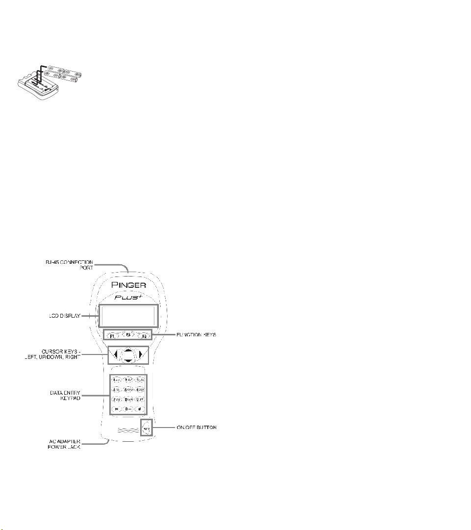
The Pinger Plus operates on four AA
alkaline batteries. Remove the battery cover
at the back of the unit and insert the batteries
with the orientation as shown. Battery polarity
is marked inside the battery well for reference.
TECHNICAL OVERVIEW
The Pinger Plus Network IP Tester uses the “PING” function to send
a data packet to another IP address on a network or respond to a PING
sent to its own IP address. The PING test is used to verify connectivity,
measure round trip communications time, check data integrity, determine
a MAC address and search a stored list or a range of IP addresses. The
Pinger Plus provides a DHCP Client mode and a Port Identification
function with selectable blink rates to locate which port on a hub or
switch that a wall outlet is connected.
NETWORK COMPATIBILITY
The Pinger Plus is designed for testing an Ethernet network that
uses the IP protocol. The unit can communicate directly with a hub,
switch, router, NIC or other network device that uses 10baseT or
100baseT. The Pinger Plus will identify when it is connected to a
1000baseT device but it cannot transmit/receive a PING at 1000baseT.
MECHANICAL FEATURES
WEB BROWSER INTERFACE
The Pinger Plus can be configured by connecting it to the network
and using either Internet Explorer (6.0 or later) or Netscape (6.0 or later).
To access the Pinger Plus setup page, enter the Pinger IP address
(shown in the Pinger IP Address setup screen) in the browser URL
window. All setup features can be configured from the browser. The
User Guide can also be displayed.
PINGER IP SETUP SCREEN
The IP address for the Pinger Plus is input from this screen. The
unit comes programmed with a default address of 192.168.1.42.
SUBNET MASK SETUP SCREEN
To Ping an IP address in a subnet different than the subnet of the
Pinger Plus, requires that the Subnet Mask be entered and “ON” and the
appropriate Gateway IP address has been entered. Mask “ON” and
OFF” is selected with the Up/Down Cursor key. A zero in the first field is
an invalid mask entry and the Pinger defaults to 255 when the mask is
saved.
NOTE: Subnet Mask and Default Gateway IP address may be found by
going to a computer on the subnet where the Pinger Plus will be used,
open the Windows Control Panel, open the network icon, open the LAN
Icon, select TCP/IP Protocol and then select properties.
GATEWAY SETUP SCREEN
The IP address for the default Gateway (typically a router or a
server) is input from this screen.
PINGER MAC SCREEN
The Pinger Plus MAC address is displayed in this screen. The
MAC for each Pinger is unique and can not be changed. See Note in
DHCP.
PROFILE SETUP SCREEN
A profile consists of a Profile name, Pinger Plus IP address, Subnet
Mask on or off, Subnet Mask, Gateway Address and a list of one to eight
destination IP addresses. One of the eight Profiles is selected using the
Up/Down cursor, the Profile name and Pinger Plus IP address is entered
and the Next function key is pressed. The Subnet Mask is entered and
turned on or off and the Next fuction key is pressed. The Gateway
address is entered and the Next function key is pressed. From one to
eight destination IP addresses are entered and then the Save function
key is pressed.
DEFAULT PROFILE SCREEN
A default profile can be designated to be used initially when the
Pinger Plus is powered on.
POWER DOWN SETUP SCREEN
The Pinger Plus will automatically turn off after the time selected in
the Power Down Setup screen. Settings available are five minutes,
fifteen minutes, thirty minutes and on (must be turned off manually).
Press the SAVE function key to store the selected setting.
PASSWORD SCREEN
A password is required to configure the Pinger Plus from a web
browser or update the firmware. The password protects against a third
party making unauthorized changes to the unit when it is connected to a
network. The default password is 12345678. It is recommended that the
default password be changed prior to initial operation.
PING COUNT, PACKET SIZE AND TIMEOUT SCREENS
The Pinger Plus can be set to PING an IP address from 1 to 99
times. The PING packet size has six settings from 50 to 1400 bytes.
The time the Pinger Plus waits for a PING or DHCP response before
displaying a No Response notice can be set from 1 to 40 seconds in
one second increments.
Page 3
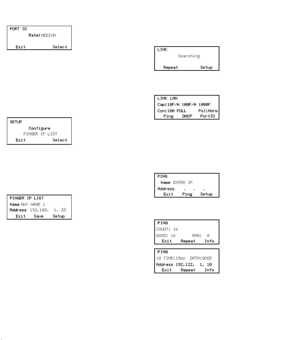
PORT ID SCREEN
Pressing the PortID function key in the Link Screen presents the
Port ID Screen. As soon as this screen appears, the Pinger begins
transmitting a pattern of Link signals
that will cause the hub,switch or NIC
Link LED to blink or stay on continuously. Identifying the specific port a
wall outlet/PC is connected to can aid
in diagnosing the cause of failed PING tests. Hubs and switches from
various manufacturers have different specifications for the time it takes
for Link signals to turn the Link LED on and off. The Pinger Plus has four
different blink rates and a continuous mode that can be selected by
pressing the Up/Down cursor key. An initial test directly at the hub or
switch will determine the best blink rate setting before conducting a
Port ID test at a wall outlet.
SETUP
Pressing the SETUP key in any screen presents the Setup
Screen.The Up/Down cursor key is used to display: 1) Pinger IP
Address Setup 2) Pinger Subnet Mask
Setup 3) Pinger Gateway Setup 4)
Pinger IP List Setup 5) Pinger MAC
Screen 6) Profile Setup 7) Default
Profile 8) Ping Count 9) Packet Size
10)Time Out 11) Power Down Time Setup 12) Password Setup or 13)
Pinger Update . Press the SELECT function key to enter the displayed
setup screen. The Pinger MAC is shown for information only and can
not be changed.
IP LIST SETUP SCREEN
The IP List Setup screen is used to enter from one to eight names and
IP addresses. The Pinger can then PING the entries individually or PING all
entries sequentially.
Data Entry - Use the Up/Down cursor key to select one of the eight storage
locations and press the right arrow key
to display the cursor and begin entering
a new name or editing an existing one.
Use the data entry keypad to input the number or letter (each time the key
is pressed the next letter or number on the key is displayed). Pressing the
right cursor key advances to the next character. Pressing the left cursor
key selects the previous character. Names can be a maximum of ten
characters long. Pressing the right cursor key an eleventh time advances
the cursor to the IP Address which is divided into four fields of three
characters. Only numbers can be input in the fields and the maximum
valid number for any field is 255. Single digits can be entered in any of the
three character locations and will be right hand justified when the cursor is
moved to the next field. Two digit numbers can be entered in the left two or
right two character locations. If an invalid number is entered, the cursor will
not advance to the next field. After entering or editing the name and IP
address, press the SAVE function key to store the information in non-volatile
memory. The information is retained even if the unit is turned off or the
batteries are removed. To remove an entry from the list, press the right
cursor key to select the entry and then press the star key. A “Delete Entry”
message is displayed and pressing the SAVE function key clears the
selected name and IP Address.
OPERATION
To test a hub, switch, router or NIC connect a patch cable from the
RJ-45 port on the equipment to the RJ-45 jack on the Pinger Plus.
LINK SCREEN
Turn on the Pinger Plus by pressing the “PWR” button. The unit
scans the RJ-45 connection searching for Link signals. If no Link signals
are found, a “No Link” message is
displayed and a REPEAT function is
provided to rerun the search for a Link
Partner. When proper Link signals are
found, the Pinger Plus displays the
connection as a LAN, NIC or an Auto MDI-X port; the capabilites of the
Link Partner; the speed and duplex the Pinger is using for the connection
and the polarity of the connection (normal or reversed). When the Link is
established, the PING, DHCP and
PortID function keys are displayed.
Disconnecting the Pinger will cause the
unit to immediately restart the search
for Link signals.
Note: If a Link Partner is transmitting NLP or MLT-3 Link signals instead
of a Link Code Word, the duplex mode is unknown (shown as “UN” in
the LINK screen) and the Pinger Plus will always connect at half duplex.
PING tests can still be run even if there is a duplex mode mismatch.
PING SCREEN
Pressing the PING function key in the Link Screen presents the
PING Screen. The Up/Down cursor key is used to select: 1) enter and
PING a new IP address 2) PING one of eight preprogrammed IP
addresses (see IP List Setup) 3) PING
all of the one to eight preprogrammed
IP LIST addresses 4) PING a Range of
IP addresses or 5) PING one of eight
Profiles(see Profile Setup).
When an IP Address, IP List or IP Range is selected, pressing the
PING function key transmits the PING packet and “Wait” is displayed
until a response is received. A summary of the PING responses is
displayed showing the number of
PINGs transmitted and the number of
Good and Bad responses. Pressing the
Up/Down cursor key shows, in
numerical order, the results of each
PING including the Round Trip Time
and if the received data is identical to
the transmitted data (Data:Good) or the
data has been corrupted (Data:Bad).
Pressing the INFO function key
displays the MAC address of the PINGed IP address. If no PING
response is received within specified Timeout time (see Timeout Setup),
“No Response” is displayed. When the PINGed IP address is in a
different subnet than the Pinger IP address, the unit first attempts to locate
the default gateway. If the gateway does not respond, the Pinger
displays a “NOGW” message indicating either the gateway is not
operating properly or an incorrect gateway IP address was entered.
When a PING response is received from another subnet, the MAC
address of the Gateway is shown (GW MAC) by pressing the Info key.
Page 4
Note: When the IP address of the device being PINGed is in the same
subnet/VLAN as the IP address of the Pinger, the Subnet Mask can be
“ON” or “OFF” and a Gateway IP address is not required. When the IP
address is in a different subnet/VLAN, the Subnet Mask must be “ON”
with the mask entered and the IP address of the Gateway must be
entered. (See Subnet Mask Setup and Gateway Setup).
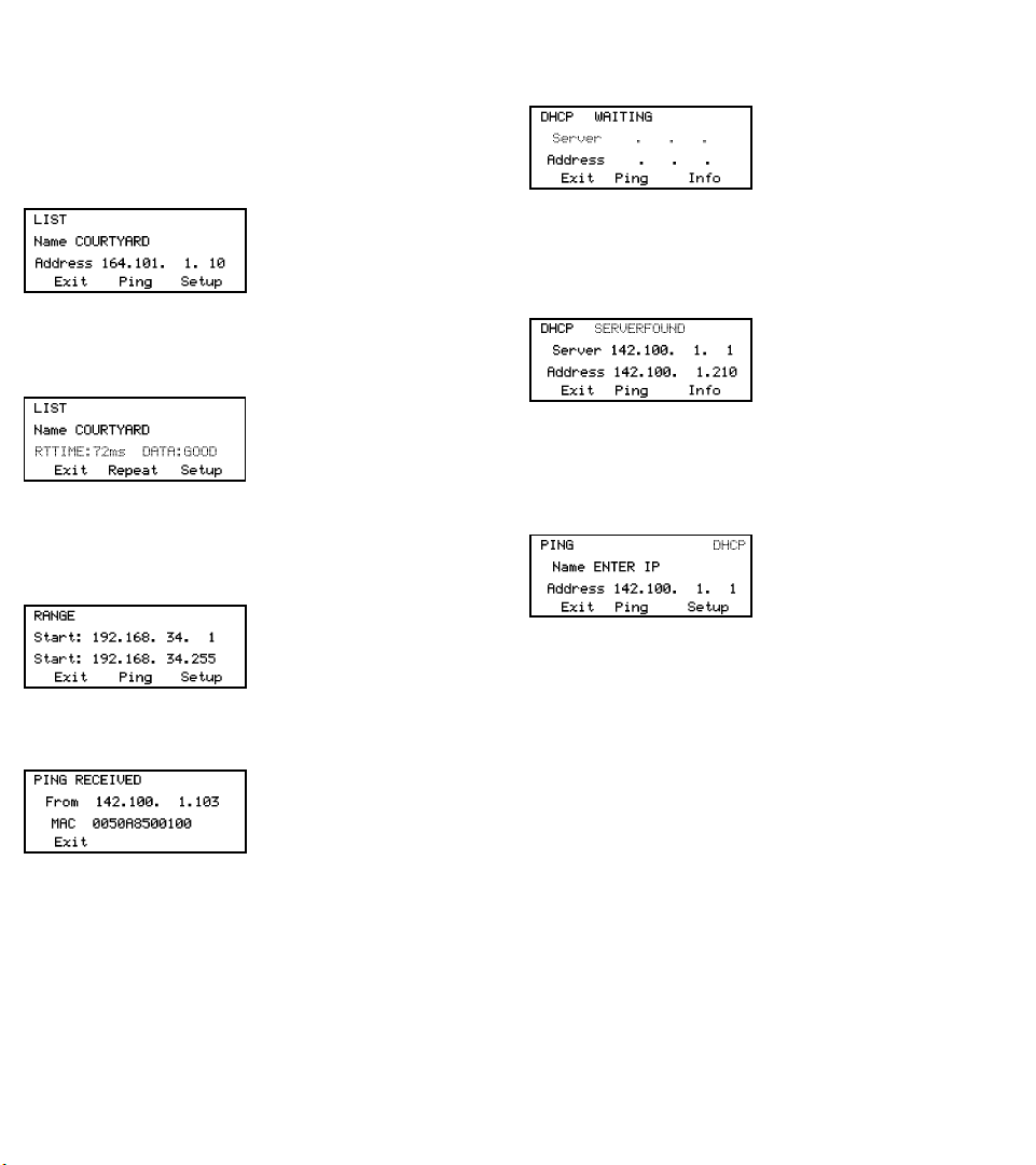
LIST SCREEN
When “IP List” is selected and the PING function key is pressed,
each IP address stored in the IP List (see IP List Setup) is PINGed in
turn. The same “Wait” and “No
Response” messages are displayed
as described above. After completing
the PING of the last stored IP address,
the IP List Reponse screen is shown.
LIST RESPONSE SCREEN
The List Response screen shows the results of the PING to each of
the stored IP addresses. The Up/Down cursor key is used to scroll through
each IP address with Round Trip Time, Data status and MAC address
presented for IP addresses that are found
or “No Response” for IP addresses that
did not respond within the Timeout period. Times that are less than one second are shown in milli-seconds (ms).
RANGE SCREEN
When “Range” is selected, the Range screen is displayed with
start and stop IP addresses. The first three octets of the start and stop
address must be the same and the fourth octet defines the range from
one to a maximum of 255 IP addresses. Pressing the PING function key
PINGs all the addresses in the range
simultaneously. Each PING response
can be viewed by pressing the Up/
Down cursor key. Holding the key will
cause the responses to scroll faster.
PING RESPONDER MODE
The Pinger Plus will respond to a PING request that is sent to the
unit’s IP address. When the unit is in the LINK Screen, a PING to the
Pinger Plus IP address presents the
PING Received screen. The Ping
Received screen shows the IP and
MAC addresses of the PING source.
DHCP SCREEN
Pressing the DHCP function key in the Link Screen presents the
DHCP Screen and begins the DHCP client-server test.
Note: The MAC Address of the Pinger
Plus may have to be added to the
Access List of the DHCP Server for the
Pinger messages to be accepted - see
your System Administrator for
requirements.
The Pinger Plus transmits a “Discover” message to locate a DHCP
server. If no DHCP Server responds to the message within the DHCP
Timeout period (see Timeout Setup), the Pinger will retransmit the
“Discover” message up to three more times. If no DHCP Server
responds after the fourth attempt, “No Response” is displayed. When a
DHCP Server responds to the
message, the Pinger displays “Server
Found” the IP Address of the Server
and the IP Address assigned to the
Pinger.
Pressing the INFO key displays the Gateway IP Address and the
Subnet Mask used with the IP Address assigned by the DHCP Server.
Note: If the DHCP Server does not provide the Gateway IP Address, a
0.0.0.0 IP Address is displayed.
Pressing the PING key while in the DHCP Client mode presents the
PING screen with a “DHCP” message
displayed and the IP Address of the
Gateway. If Gateway information is not
available, the DHCP Server IP Address
is shown.
Pressing the PING key from the IP Ping Screen transmits a PING
that uses the IP Address, Gateway Address and Subnet Mask provided
by the DHCP Server instead of the IP Address, Gateway Address and
Subnet Mask that were previously entered and stored in the Pinger. The
Gateway IP Address is automatically entered as the address to be
PINGed (or the DHCP Server address when Gateway information is not
available). Alternatively, a new IP Address can be entered or the Up/
Down cursor key can be used to select a previously stored address.
Pressing the EXIT key returns the Pinger back to the LINK Screen and
clears the DHCP Server assigned addresses and mask. Pressing the
Setup key also clears the DHCP Server assigned information and
transmits a DHCP release packet to the DHCP server so that the IP
address is available for reassignment.
 Loading...