

Page 1
USER GUIDE
CableTracker 12
3. Off
CableTracker 12
PSIBER
TEST
PSIBER
WARRANTY
Psiber Data Systems Inc. warrants that the product
shall be free from defects in parts or workmanship for
a period of 12 months from the date of purchase if
used in accordance with Psiber Data Systems Inc.
operating specifications.
THIS IS THE ONLY WARRANTY MADE BY Psiber
Data Systems Inc. AND IS EXPRESSLY MADE IN
LIEU OF ALL OTHER WARRANTIES EXPRESSED
OR IMPLIED, INCLUDING BUT NOT LIMITED TO
ANY IMPLIED WARRANTIES OF MERCHANTABILITY
OR FITNESS FOR ANY PARTICULAR PURPOSE.
Should any parts or workmanship prove defective,
Psiber Data Systems Inc. will repair or replace at
Psiber Data Systems’ option, at no cost to the Buyer
except for shipping costs from the Buyer’s location to
Psiber Data Systems Inc. This is Buyer’s SOLE AND
EXCLUSIVE REMEDY under this Agreement. This
warranty does not apply to products which have been
subject to neglect, accident or improper use, or to units
which have been altered or repaired by other than an
authorized repair facility.
Return of Equipment to Psiber Data Systems Inc.
Simply obtain a Return Authorization number from our
Customer Service by calling 619-287-9970. Clearly
mark the RMA# on the shipping label, so the package
can be accepted at Psiber Data Systems Inc.
CableTracker, PSIBER and the PSIBER logo are trademarks of
Psiber Data Systems Inc. Copyright 2015 Psiber Data Systems
Inc. All rights reserved. Part No. 1005-0120-0000 Rev B
USER GUIDE
CableTracker 12
3. Off
CableTracker 12
PSIBER
TEST
PSIBER
USER GUIDE
CableTracker 12
3. Off
CableTracker 12
PSIBER
TEST
PSIBER
USER GUIDE
CableTracker 12
3. Off
CableTracker 12
PSIBER
LowBatt
Auto
Tone
TEST
PSIBER
WARRANTY
Psiber Data Systems Inc. warrants that the product
shall be free from defects in parts or workmanship for
a period of 12 months from the date of purchase if
used in accordance with Psiber Data Systems Inc.
operating specifications.
THIS IS THE ONLY WARRANTY MADE BY Psiber
Data Systems Inc. AND IS EXPRESSLY MADE IN
LIEU OF ALL OTHER WARRANTIES EXPRESSED
OR IMPLIED, INCLUDING BUT NOT LIMITED TO
ANY IMPLIED WARRANTIES OF MERCHANTABILITY
OR FITNESS FOR ANY PARTICULAR PURPOSE.
Should any parts or workmanship prove defective,
Psiber Data Systems Inc. will repair or replace at
Psiber Data Systems’ option, at no cost to the Buyer
except for shipping costs from the Buyer’s location to
Psiber Data Systems Inc. This is Buyer’s SOLE AND
EXCLUSIVE REMEDY under this Agreement. This
warranty does not apply to products which have been
subject to neglect, accident or improper use, or to units
which have been altered or repaired by other than an
authorized repair facility.
Return of Equipment to Psiber Data Systems Inc.
Simply obtain a Return Authorization number from our
Customer Service by calling 619-287-9970. Clearly
mark the RMA# on the shipping label, so the package
can be accepted at Psiber Data Systems Inc.
CableTracker, PSIBER and the PSIBER logo are trademarks of
Psiber Data Systems Inc. Copyright 2015 Psiber Data Systems
Inc. All rights reserved. Part No. 1005-0120-0000 Rev B
WARRANTY
Psiber Data Systems Inc. warrants that the product
shall be free from defects in parts or workmanship for
a period of 12 months from the date of purchase if
used in accordance with Psiber Data Systems Inc.
operating specifications.
THIS IS THE ONLY WARRANTY MADE BY Psiber
Data Systems Inc. AND IS EXPRESSLY MADE IN
LIEU OF ALL OTHER WARRANTIES EXPRESSED
OR IMPLIED, INCLUDING BUT NOT LIMITED TO
ANY IMPLIED WARRANTIES OF MERCHANTABILITY
OR FITNESS FOR ANY PARTICULAR PURPOSE.
Should any parts or workmanship prove defective,
Psiber Data Systems Inc. will repair or replace at
Psiber Data Systems’ option, at no cost to the Buyer
except for shipping costs from the Buyer’s location to
Psiber Data Systems Inc. This is Buyer’s SOLE AND
EXCLUSIVE REMEDY under this Agreement. This
warranty does not apply to products which have been
subject to neglect, accident or improper use, or to units
which have been altered or repaired by other than an
authorized repair facility.
Return of Equipment to Psiber Data Systems Inc.
Simply obtain a Return Authorization number from our
Customer Service by calling 619-287-9970. Clearly
mark the RMA# on the shipping label, so the package
can be accepted at Psiber Data Systems Inc.
CableTracker, PSIBER and the PSIBER logo are trademarks of
Psiber Data Systems Inc. Copyright 2015 Psiber Data Systems
Inc. All rights reserved. Part No. 1005-0120-0000 Rev B
WARRANTY
Psiber Data Systems Inc. warrants that the product
shall be free from defects in parts or workmanship for
a period of 12 months from the date of purchase if
used in accordance with Psiber Data Systems Inc.
operating specifications.
THIS IS THE ONLY WARRANTY MADE BY Psiber
Data Systems Inc. AND IS EXPRESSLY MADE IN
LIEU OF ALL OTHER WARRANTIES EXPRESSED
OR IMPLIED, INCLUDING BUT NOT LIMITED TO
ANY IMPLIED WARRANTIES OF MERCHANTABILITY
OR FITNESS FOR ANY PARTICULAR PURPOSE.
Should any parts or workmanship prove defective,
Psiber Data Systems Inc. will repair or replace at
Psiber Data Systems’ option, at no cost to the Buyer
except for shipping costs from the Buyer’s location to
Psiber Data Systems Inc. This is Buyer’s SOLE AND
EXCLUSIVE REMEDY under this Agreement. This
warranty does not apply to products which have been
subject to neglect, accident or improper use, or to units
which have been altered or repaired by other than an
authorized repair facility.
Return of Equipment to Psiber Data Systems Inc.
Simply obtain a Return Authorization number from our
Customer Service by calling 619-287-9970. Clearly
mark the RMA# on the shipping label, so the package
can be accepted at Psiber Data Systems Inc.
CableTracker, PSIBER and the PSIBER logo are trademarks of
Psiber Data Systems Inc. Copyright 2015 Psiber Data Systems
Inc. All rights reserved. Part No. 1005-0120-0000 Rev B
On Short
LowBatt
Auto
Tone
On Short
LowBatt
Auto
Tone
On Short
LowBatt
Auto
Tone
On Short
Page 2
BATTERY
Use one 9 volt alkaline battery.
BATTERY INSTALLATION
Remove the battery cover on the back of the unit,
connect the battery to the battery snap cable, insert the
battey in the battery well and replace the battery cover.
OVERVIEW
The CableTracker12 Tone Generator (CT12) is used to
identify cables and terminations.
1. The CT12 Tone Generator transmits a trace tone on
a connected cable which is detected with a
CableTracker 15 (CT15) or other compatible probe.
2. When the CT15 Probe is near the connected cable
or punchdown, it indicates detection by emitting the
audio signal transmited by the CT12 Tone Generator.
3. The CT12 Continuity test utilizes a bi-colored LED to
indicate resistance between the test leads. The test
displays Opens, Shorts and High Resistance Short.
CONTENTS
• Model 12 Tone Generator
• User Guide
• Battery
• RJ-45 Patch Cable
• RJ-45 to Alligator Clips Adapter
• RJ-45 to BNC and BNC to F Adapters (Optional)
• RJ-45 to Bed of Nails Alligator Clips Adapter (Optional)
CONNECTION
Connect the CT12 Tone Generator directly to an RJ-45
or RJ-11 terminated cable; or an RJ-45 wall outlet using
the RJ-45 Patch Cable; or bare wire by connecting the
RJ-45 to Alligator Clips Adapter. The CT12 transmits an
alternating tone signal through the connected cable.
OPERATION
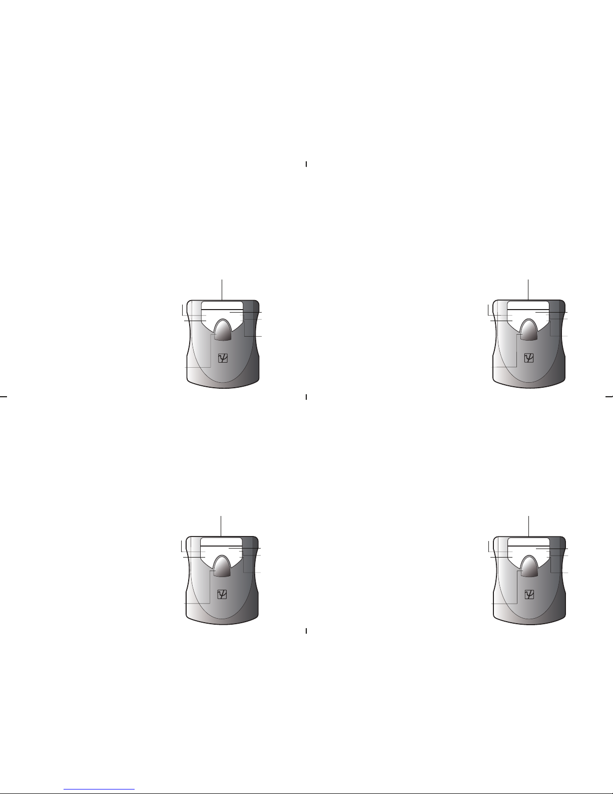
The CableTracker 12 Tone Generator features one
button operation. Each press of the TEST button
advances the operating mode of the unit. The modes are
selected in the following order:
1. Auto/Tone - Alternating tone will automatically
turn off after approximately 10 minutes.
2. On/Tone - Alternating tone will not turn off
until the test button is pressed again.
3. Off
CableTracker 12
Test Button
RJ-45 Connector
SHORT Continuity test
indicates the
resistance
between the test
leads.
AUTO - Transmits a tone
signal or tests continuity
for 10 minutes and then
shuts down to conserve
battery life.
LOW BATTERY - When the
battery is below the level
required for the CT12 to
operate properly,
the “LowBatt”
indicator
illuminates.
4. Off - No signal transmited.
PSIBER
LowBatt
Auto
Tone
TEST
On Short
ON - A
tone signal
transmits
continuously
until the
operator
selects Test
again.
TONE - A tone
signal is transmited
3. Auto/Short - Continuity test indicates the resistance
between the test leads. LED Color Resistance:
Green (Open) R ≥ 300KΩ
Orange (High Resistance Short) 5KΩ < R < 300KΩ
Red (Short) R ≤ 5KΩ
BATTERY
Use one 9 volt alkaline battery.
BATTERY INSTALLATION
Remove the battery cover on the back of the unit,
connect the battery to the battery snap cable, insert the
battey in the battery well and replace the battery cover.
OVERVIEW
The CableTracker12 Tone Generator (CT12) is used to
identify cables and terminations.
1. The CT12 Tone Generator transmits a trace tone on
a connected cable which is detected with a
CableTracker 15 (CT15) or other compatible probe.
2. When the CT15 Probe is near the connected cable
or punchdown, it indicates detection by emitting the
audio signal transmited by the CT12 Tone Generator.
3. The CT12 Continuity test utilizes a bi-colored LED to
indicate resistance between the test leads. The test
displays Opens, Shorts and High Resistance Short.
CONTENTS
• Model 12 Tone Generator
• User Guide
• Battery
• RJ-45 Patch Cable
• RJ-45 to Alligator Clips Adapter
• RJ-45 to BNC and BNC to F Adapters (Optional)
• RJ-45 to Bed of Nails Alligator Clips Adapter (Optional)
CONNECTION
Connect the CT12 Tone Generator directly to an RJ-45
or RJ-11 terminated cable; or an RJ-45 wall outlet using
the RJ-45 Patch Cable; or bare wire by connecting the
RJ-45 to Alligator Clips Adapter. The CT12 transmits an
alternating tone signal through the connected cable.
BATTERY
Use one 9 volt alkaline battery.
BATTERY INSTALLATION
Remove the battery cover on the back of the unit,
connect the battery to the battery snap cable, insert the
battey in the battery well and replace the battery cover.
OVERVIEW
The CableTracker12 Tone Generator (CT12) is used to
identify cables and terminations.
1. The CT12 Tone Generator transmits a trace tone on
a connected cable which is detected with a
CableTracker 15 (CT15) or other compatible probe.
2. When the CT15 Probe is near the connected cable
or punchdown, it indicates detection by emitting the
audio signal transmited by the CT12 Tone Generator.
3. The CT12 Continuity test utilizes a bi-colored LED to
indicate resistance between the test leads. The test
displays Opens, Shorts and High Resistance Short.
CONTENTS
• Model 12 Tone Generator
• User Guide
• Battery
• RJ-45 Patch Cable
• RJ-45 to Alligator Clips Adapter
• RJ-45 to BNC and BNC to F Adapters (Optional)
• RJ-45 to Bed of Nails Alligator Clips Adapter (Optional)
CONNECTION
Connect the CT12 Tone Generator directly to an RJ-45
or RJ-11 terminated cable; or an RJ-45 wall outlet using
the RJ-45 Patch Cable; or bare wire by connecting the
RJ-45 to Alligator Clips Adapter. The CT12 transmits an
alternating tone signal through the connected cable.
BATTERY
Use one 9 volt alkaline battery.
BATTERY INSTALLATION
Remove the battery cover on the back of the unit,
connect the battery to the battery snap cable, insert the
battey in the battery well and replace the battery cover.
OVERVIEW
The CableTracker12 Tone Generator (CT12) is used to
identify cables and terminations.
1. The CT12 Tone Generator transmits a trace tone on
a connected cable which is detected with a
CableTracker 15 (CT15) or other compatible probe.
2. When the CT15 Probe is near the connected cable
or punchdown, it indicates detection by emitting the
audio signal transmited by the CT12 Tone Generator.
3. The CT12 Continuity test utilizes a bi-colored LED to
indicate resistance between the test leads. The test
displays Opens, Shorts and High Resistance Short.
CONTENTS
• Model 12 Tone Generator
• User Guide
• Battery
• RJ-45 Patch Cable
• RJ-45 to Alligator Clips Adapter
• RJ-45 to BNC and BNC to F Adapters (Optional)
• RJ-45 to Bed of Nails Alligator Clips Adapter (Optional)
CONNECTION
Connect the CT12 Tone Generator directly to an RJ-45
or RJ-11 terminated cable; or an RJ-45 wall outlet using
the RJ-45 Patch Cable; or bare wire by connecting the
RJ-45 to Alligator Clips Adapter. The CT12 transmits an
alternating tone signal through the connected cable.
OPERATION
The CableTracker 12 Tone Generator features one
button operation. Each press of the TEST button
advances the operating mode of the unit. The modes are
selected in the following order:
1. Auto/Tone - Alternating tone will automatically
turn off after approximately 10 minutes.
2. On/Tone - Alternating tone will not turn off
until the test button is pressed again.
3. Off
CableTracker 12
Test Button
RJ-45 Connector
SHORT Continuity test
indicates the
resistance
between the test
leads.
AUTO - Transmits a tone
signal or tests continuity
for 10 minutes and then
shuts down to conserve
battery life.
LOW BATTERY - When the
battery is below the level
required for the CT12 to
operate properly,
the “LowBatt”
indicator
illuminates.
4. Off - No signal transmited.
PSIBER
LowBatt
Auto
Tone
TEST
On Short
ON - A
tone signal
transmits
continuously
until the
operator
selects Test
again.
TONE - A tone
signal is transmited
3. Auto/Short - Continuity test indicates the resistance
between the test leads. LED Color Resistance:
Green (Open) R ≥ 300KΩ
Orange (High Resistance Short) 5KΩ < R < 300KΩ
Red (Short) R ≤ 5KΩ
OPERATION
The CableTracker 12 Tone Generator features one
button operation. Each press of the TEST button
advances the operating mode of the unit. The modes are
selected in the following order:
1. Auto/Tone - Alternating tone will automatically
turn off after approximately 10 minutes.
2. On/Tone - Alternating tone will not turn off
until the test button is pressed again.
3. Off
CableTracker 12
Test Button
RJ-45 Connector
SHORT Continuity test
indicates the
resistance
between the test
leads.
AUTO - Transmits a tone
signal or tests continuity
for 10 minutes and then
shuts down to conserve
battery life.
LOW BATTERY - When the
battery is below the level
required for the CT12 to
operate properly,
the “LowBatt”
indicator
illuminates.
4. Off - No signal transmited.
PSIBER
LowBatt
Auto
Tone
TEST
On Short
ON - A
tone signal
transmits
continuously
until the
operator
selects Test
again.
TONE - A tone
signal is transmited
3. Auto/Short - Continuity test indicates the resistance
between the test leads. LED Color Resistance:
Green (Open) R ≥ 300KΩ
Orange (High Resistance Short) 5KΩ < R < 300KΩ
Red (Short) R ≤ 5KΩ
OPERATION
The CableTracker 12 Tone Generator features one
button operation. Each press of the TEST button
advances the operating mode of the unit. The modes are
selected in the following order:
1. Auto/Tone - Alternating tone will automatically
turn off after approximately 10 minutes.
2. On/Tone - Alternating tone will not turn off
until the test button is pressed again.
3. Off
CableTracker 12
Test Button
RJ-45 Connector
SHORT Continuity test
indicates the
resistance
between the test
leads.
AUTO - Transmits a tone
signal or tests continuity
for 10 minutes and then
shuts down to conserve
battery life.
LOW BATTERY - When the
battery is below the level
required for the CT12 to
operate properly,
the “LowBatt”
indicator
illuminates.
4. Off - No signal transmited.
PSIBER
LowBatt
Auto
Tone
TEST
On Short
ON - A
tone signal
transmits
continuously
until the
operator
selects Test
again.
TONE - A tone
signal is transmited
3. Auto/Short - Continuity test indicates the resistance
between the test leads. LED Color Resistance:
Green (Open) R ≥ 300KΩ
Orange (High Resistance Short) 5KΩ < R < 300KΩ
Red (Short) R ≤ 5KΩ
 Loading...