

Page 1

User's Manual
P P 2 0 2 4
5112 991 14564
Acknowledgements
PCL is a Trademark of Hewlett-Packard Corporation.
A Publication of PSi Printer Systems international GmbH
Eiserfelder Straße 316
57080 Siegen @ Germany
http://www.psi-si.de
Version: 5112 991 14564 January 2000
Order No.: 8708 294 00010
Great care has been taken to ensure that the information in this handbook is accurate and complete.
However, should any errors or omissions be discovered or should any user wish to make suggestions
for improving this handbook, please feel encouraged to send us the relevant details.
The contents of this manual are subject to change without notice.
Copyright © by PSi Printer Systems international.
All rights strictly reserved. Reproduction or issue to third parties in any form is not permitted without
written authorization from the publisher.
Page 2

I II
Safety Regulations for the Laser Printer PP 2024 Electromagnetic Compatibility
The laser printer PP 2024 fulfils the safety regulations according to IEC and Type: Printer PP 2024
TÜV/GS for computer systems (EN 60950) and laser products (EN 60825-1).
UL 1950 3rd Edition / CAN/CSA C22.2 No 950-95; 21 CFR 1040.10 and corresponds to the law regulations ruling electromagnetic compatibility of
1040.11. appliances (89/336/EWG) and, therefore, fulfils the requirements for conformity
The mains cable must be connected to a ground protected wall-socket. The
selected voltage of the printer needs to be in accordance with the local mains
voltage.
The power plug must be easily accessible at any time so that it can be
disconnected immediately in case of danger or for maintenance purposes.
Before installing the printer, check the surrounding conditions in which the
printer is intended to be used (see next page, Operating Environment).
During thunderstorm you should never attempt to connect or disconnect any
data transfer cable.
The power supply should only be opened and checked by authorized personnel.
Repairs and maintenance beyond the descriptions of chapter 5 may only be
attempted by authorized personnel as well. Repairs done inappropriately may
cause damage to the device and severe danger for the user.
Caution: The use of controls or adjustments or performance of procedures
other than those specified herein may result in hazardous radiation
exposure.
During the printing process ozone will be produced. Take care that
the printer is standing in a room with good ventilation. The limt of
ozone concentration should be 0,1 ppm (0,2 mg/m). Note that the
3
specific gravity of ozone is higher than that of air.
We certify that the equipment at issue,
marking with the CE-sign.
Note: This equipment has bee tested and found to comply with the limits for a
CLASS A digital device pursuant to Part 15 of the FCC Rules. These
limits are designed to provide reasonable protection against harmful
interference when the equipment is operated in a commercial
environment. This equipment generates, uses, and can radiate radio
frequency energy and, if not installed and used in accordance with the
instruction manual, may cause harmful interference to radio
communications. Operation of this equipment in a residential area is
likely to cause harmful interference in wich case the user will be required
to correct the interference at his own expense.
To guarantee that the device stays within the limits according to the approval
regulations for conducted and radiated emission (EN 55022, Class B) and
immunity according to EN 50081-1, Generic Standard in any case shielded
interface cables are to be used only.
Changes and modifications not explicitly allowed by the equipment's
manufacturer could void the user's authority to operate the equipment.
Operating Environment
Avoid installing the printer where it is exposed to moisture or heat (eg. direct sun
light).
- Temperature: + 10EC to + 32.5EC (+50EF to +90.5EF)
- Humidity: 20% to 80%
Slots and openings in the printer's housing are provided for ventilation. Always
ensure that these openings are not obstructed.
Also ensure that the cables at the rear of the printer do not interfere with the
output paper path.
Page 3

III IV
Safety Regulations for the intelligent Paper Stacker iPS 2024
The intelligent Paper Stacker iPS 2024 fulfils the safety regulations according
to IEC and VDE/GS for computer systems (EN 60950);
UL 1950 3rd Edition, CAN/CSA C22.2 No.950-95.
The mains cable must be connected to a ground protected wall-socket. The
selected voltage of the intelligent paper stacker needs to be in accordance with
the local mains voltage.
The power plug must be easily accessible at any time so that it can be
disconnected immediately in case of danger or for maintenance purposes.
Before installing the intelligent paper stacker, check the surrounding conditions
in which the intelligent paper stacker is intended to be used (see next page,
Operating Environment).
During thunderstorm you should never attempt to connect or disconnect any
power cable.
The power supply should only be opened and checked by authorized personnel.
Repairs may only be attempted by authorized personnel as well. Repairs done
inappropriately may cause damage to the device and severe danger for the
user.
Caution, the chain of the motor to move the paper exit tray
up and down will start automatically or after pushing the
key at the left side of the table.
Electromagnetic Compatibility
We certify that the equipment at issue,
Type: intelligent Paper Stacker iPS 2024
corresponds to the law regulations ruling electromagnetic compatibility of
appliances (89/336/EWG) and, therefore, fulfils the requirements for conformity
marking with the CE-sign.
Note: This equipment has been tested and found to comply with the limits for a
CLASS A digital device pursuant to Part 15 of the FCC Rules. These
limits are designed to provide reasonable protection against harmful
interference when the equipment is operated in a commercial
environment. This equipment generates, uses, and can radiate radio
frequency energy and, if not installed and used in accordance with the
instruction manual, may cause harmful interference to radio
communications. Operation of this equipment in a residential area is
likely to cause harmful interference in wich case the user will be required
to correct the interference at his own expense.
To guarantee that the device stays within the limits according to the approval
regulations for conducted and radiated emission (EN 55022, Class B) and
immunity according to EN 50081-1, Generic Standard in any case shielded
interface cables are to be used only.
Changes and modifications not explicitly allowed by the equipment's
manufacturer could void the user's authority to operate the equipment.
The intelligent Paper Stacker can only be used in conjunction with the printer
PP 2024.
Operating Environment
Avoid installing the intelligent paper stacker where it is exposed to moisture or
heat (e.g. direct sun light).
- Temperature: + 10EC to + 32.5EC (+50EF to +90.5EF)
- Humidity: 20% to 80%
Also ensure that the cables at the rear of the printer do not interfere with the
output paper path. The feet of the laser printer PP 2024 should be positioned
over the four screws on the stacker's table.
Page 4

Table of Contents
V VI
Table of Contents 2. Printer Operation .............................................2-1
Preface ....................................................... XIV
About this Manual ............................................... XIV
Conventions used in this guide ..................................... XVI
1. Getting Started ...............................................1-1
1.1 Unpacking ................................................1-1
- Printer Package ......................................... 1-1
- Contents of Starter Kit Box ................................. 1-2
- Transportation Hints ......................................1-4
1.2 Installing the Consumables ...................................1-5
- Installing the Developer Unit ................................1-6
- Filling in Starter Toner ....................................1-8
- Inserting the Ozone Filter .................................1-10
- Installing the Waste Toner Container ........................1-11
- Inserting the Cleaner Felt ................................. 1-12
- Installing the OPC Drum ..................................1-13
1.3 The Power Supply .........................................1-14
1.4 Power ON/OFF Switch .....................................1-15
1.5 Inserting Fanfold Paper ..................................... 1-17
1.6 Connection to the Computer .................................1-21
1.7 Connecting the Stacker System ..............................1-22
2.1 Control Panel ..............................................2-1
2.1.1 Description of the Four Indicators ...........................2-1
2.1.2 description of the LCD Display ..............................2-2
2.1.3 Function Keys ...........................................2-3
2.2 Menu Mode ................................................2-4
2.2.1 Activate the Menu ........................................2-5
2.2.2 Confirm a new Selection ...................................2-6
2.3 Status and Error Messages ...................................2-7
3. Configuring the Printer ........................................3-1
3.1 What is Configuring .........................................3-1
3.1.1 Profiles ................................................3-1
S Profiler .................................................3-2
3.1.2 Basic Printer Settings .....................................3-2
3.1.3 Test Mode ..............................................3-2
3.2 Printout of Standard Configuration ..............................3-3
3.2.1 How to Start a SELF TEST ................................3-4
S SELF TEST Sample ......................................3-5
3.3 Printout of the 10 Profiles .....................................3-6
3.4 Menu Structure .............................................3-7
3.5 Menu Item Description .......................................3-9
S SELECT PROFILE ..........................................3-9
S PAPER MENU ........................................... 3-10
S PCL MENU .............................................. 3-11
S HEXDUMP MENU ........................................ 3-12
S GENERAL MENU ........................................ 3-13
S CONFIG MENU .......................................... 3-14
S TEST MENU ............................................. 3-15
S INFO MENU ............................................. 3-16
Page 5

Table of Contents
VII VIII
3.6 Configuration Programs .....................................3-17
S Profiler ...................................................3-17
S Profile Selector ............................................3-17
3.6.1 Installation .............................................3-17
3.6.2 Profiler ................................................ 3-18
3.6.3 Selector ............................................... 3-23
4 Explanation of Individual Menu Items ...........................4-1
4.1 Menu Mode SELECT PROFILE ...............................4-2
4.2 Menu Mode CHANGE PROFILE ..............................4-2
4.2.1 PAPER MENU .......................................... 4-2
S PAPER ............................................. 4-2
S PAPER LENGTH .....................................4-3
S LENGTH FACTOR ....................................4-3
S IMAGE WIDTH ....................................... 4-4
S ORIENTATION ....................................... 4-4
S LANDSCAPE MODE ..................................4-5
S ORIENT. MODE ......................................4-6
S PAPER EXTENDED .................................. 4-7
S PAPER SELECTION .................................. 4-7
S FUSER TEMP. .......................................4-7
S VER SHIFT .......................................... 4-7
S HOR SHIFT .........................................4-7
4.2.2 PCL MENU ............................................. 4-8
S FONT NUMBER ...................................... 4-8
S PITCH ..............................................4-8
S POINT SIZE .........................................4-8
S SYMBOL SET .......................................4-9
S LINE SPACING .....................................4-10
S TOP MARGIN .......................................4-10
S LEFT MARGIN ......................................4-10
S RIGHT MARGIN ..................................... 4-10
S TEXT LENGTH .....................................4-10
S PERF. SKIP ........................................4-10
4.2.3 HEXDUMP MENU ..................................... 4-11
S UEL COMMAND .................................... 4-11
4.2.4 GENERAL MENU ..................................... 4-12
S EMULATION ....................................... 4-12
S AUTO FORM FEED ................................. 4-12
S PAPER RETRACT .................................. 4-12
4.3 Menu Mode BASIC SETTINGS .............................. 4-13
4.3.1 CONFIG. MENU ....................................... 4-13
S POWER SAVE ..................................... 4-13
S ALARM BELL ...................................... 4-13
S LANGUAGE ....................................... 4-13
S MENU ACCESSS ................................... 4-14
S RECALL FACTORY ................................. 4-14
4.4 Menu Mode TEST MODE .................................. 4-15
4.4.1 TEST MENU .......................................... 4-15
S PANEL TEST ...................................... 4-15
S SELF TEST ........................................ 4-15
S CONT SELF TEST .................................. 4-15
S CONFIG. PRINT .................................... 4-15
S PCL TYPEFACE LIST ............................... 4-16
4.4.2 INFO MENU .......................................... 4-18
S MACHINE COUNT .................................. 4-18
S ENGINE ID ........................................ 4-18
S FIRMWARE VERSION .............................. 4-18
S STACKER VERSION ................................ 4-18
Page 6

Table of Contents
IX X
5 Maintenance .................................................5-1
5.1 Installing the Parts of the Toner Kit .............................5-1
- Filling in Toner ..........................................5-2
- Replacing the Waste Toner Container ....................... 5-4
- Changing the Cleaner Felt ................................. 5-6
5.2 Replacement of the OPC Drum ................................5-7
5.3 Replacement of the Developer Unit .............................5-9
- Filling in Starter Toner ...................................5-11
- Inserting the Ozone Filter .................................5-13
5.4 Replacement of the Fuser Unit ...............................5-14
5.5 Exchanging the Control Unit .................................5-15
6. Trouble Shooting and Diagnostics ..............................6-1
- How to Use this Section ......................................6-1
6.1 Power-related Problems ...................................... 6-2
6.2 Error Messages ............................................6-2
7. Intelligent Paper Stacker iPS 2024 ..............................7-1
7.1. Assembling the Intelligent Paper Stacker ........................7-1
7.1.1 Unpacking ............................................. 7-1
- Delivery Contents ........................................7-1
7.1.2 To Mount the Tear Off Bar .................................7-2
7.1.3 Paper Exit Tray Assembly ................................. 7-3
7.1.4 The Pendulum ..........................................7-4
7.1.5 Put the Printer onto the Table ..............................7-5
7.1.6 The Power Supply .......................................7-6
7.2. Operating the intelligent Paper Stacker ..........................7-7
7.2.1 Inserting Paper ..........................................7-7
7.2.2 Adjusting the Paper Length ................................7-8
7.2.3 Power On the intelligent Paper Stacker .......................7-9
7.2.4 Tear Off and Remove Paper ............................. 7-10
7.3. Troubleshooting and Diagnostics ............................. 7-11
7.3.1 Printer stops because of wrong page length selection ......... 7-11
7.3.2 Printer stops when the paper exit tray is full .................. 7-11
7.3.3 Paper not stacked in Right Order .......................... 7-11
7.3.4 Proceeding after Power Down or Inadvertently Power Off ...... 7-12
8. Technical Data ...............................................8-1
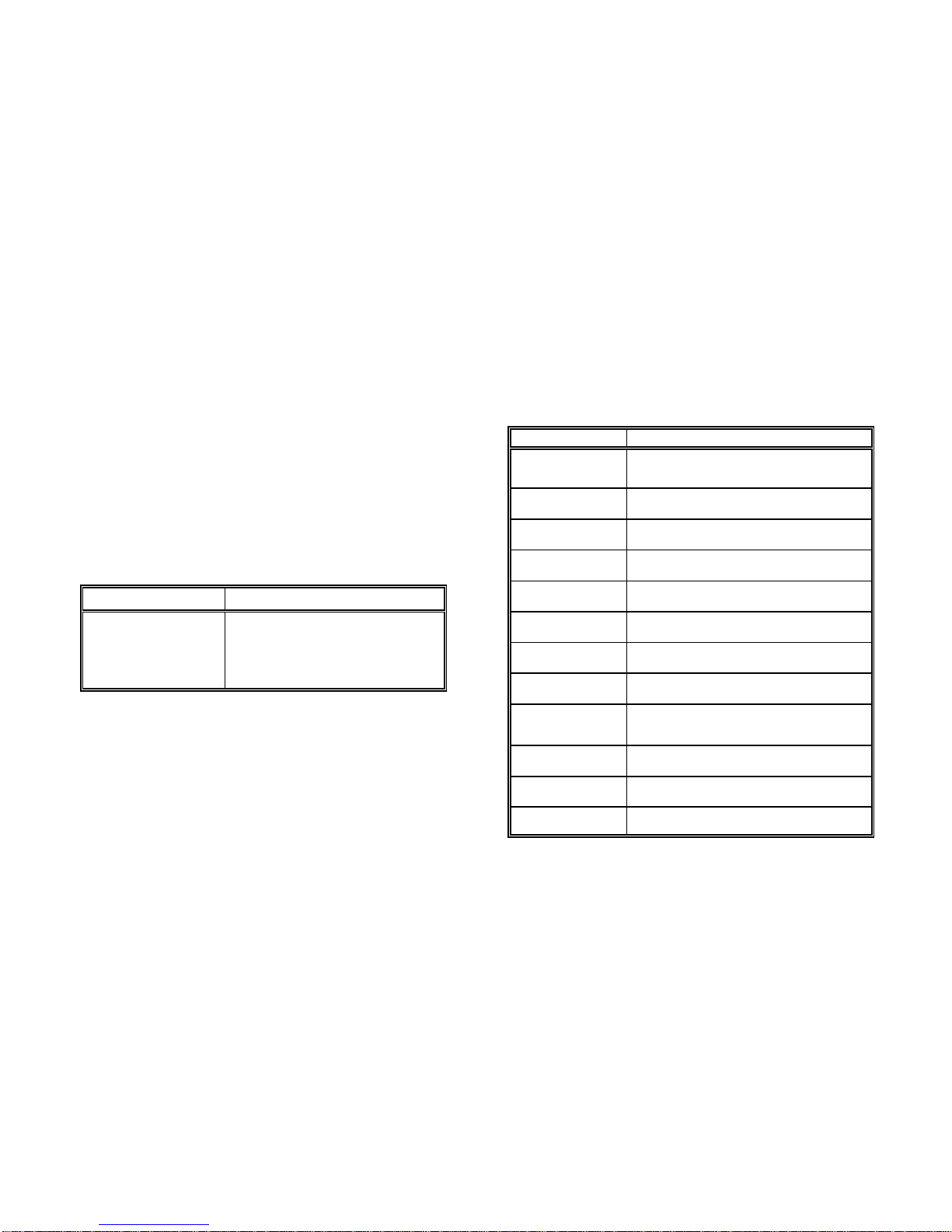
8.1 Printer Specification .........................................8-1
8.2 Paper Specification ..........................................8-3
8.3 Connectivity ................................................8-4
8.4 Consumables ..............................................8-5
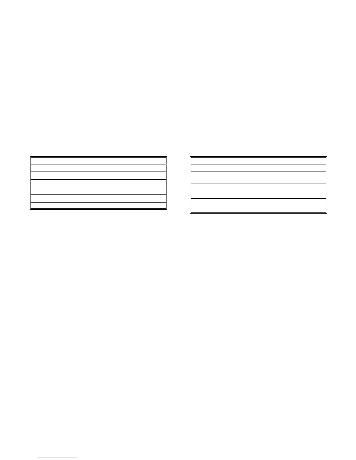
8.5 Specification of Intelligent Paper Stacker .........................8-6
8.6 Paper Specification for Intelligent Paper Stacker iPS 2024 ...........8-7
Page 7

Table of Contents
XI XII
9 Paper Specification ...........................................9-1
9.1 Basic Theory of Operation ..................................9-1
9.2 Storing Media ............................................. 9-1
9.3 Environmental Considerations .............................. 9-2
9.4 Guidelines and Specification for Selected Fanfold Paper ........ 9-2
9.4.1 General Guidelines .......................................9-3
S Quality .................................................9-3
S Basic weight ............................................9-3
S Transport holes ..........................................9-4
S Perforation .............................................9-5
9.4.2 Typical Paper Properties for Laser Printer ..................... 9-6
9.4.3 Paper / Form Properties ...................................9-7
9.4.4 Label Carrier Properties ...................................9-9
9.4.5 Label Properties ........................................9-10
10 Maintenance / Logbook ......................................10-1
10.1 Toner Kit .................................................10-1
10.2 OPC Drum ...............................................10-3
10.3 Developer Unit ............................................10-4
10.4 Fuser Unit ................................................10-5
10.5 Inspection Report ..........................................10-6
10.6 Customer Remarks ........................................10.7
Appendix A Programming Guide .................................A-1
A-1 Support of Printer Specific Features and Functions ................A-2
A-1.1 Profiles ................................................A-2
A-1.2 Paper Size Select ........................................A-2
A-1.3 Semigraphics Support under SAP R/3 .......................A-3
A-1.4 EURO Symbol Support ...................................A-3
A-1.5 Support of Logical and Physical Pages ........................A-4
A-1.7 Conventions ............................................A-5
A-2 List of Supported PJL Control Function ......................... A-6
A-2.1 Basic Rules for PJL Programming .......................... A-6
A-2.1.1 PJL Syntax Rules ................................. A-6
A-2.1.2 PJL Environments ................................. A-7
A-2.1.3 List of Supported PJL Commands .................... A-8
A-2.1.4 List of Supported PJL Variables and Values ........... A-10
A-2.1.5 List of Supported PJL Variables and Values for PCL
Personality ...................................... A-13
A-3 List of Supported PCL5 Control Functions ..................... A-14
A-3.1 Job Control Commands ................................. A-14
A-3.2 Page Control Commands ................................ A-15
A-3.3 Cursor Positioning Commands ........................... A-17
A-3.4 Font Selection Commands ............................... A-19
A-3.5 Font Management Commands ........................... A-20
A-3.6 Macro Control Commands ............................... A-21
A-3.7 Graphic Commands .................................... A-22
A-4 Support of Semigraphics for SAP/R3 ......................... A-23
A-5 Barcode Programming ..................................... A-24
A-5.1 Resident Barcode Font Code 39 HP Compatible ............. A-24
A-5.2 Resident Barcode Controlled by Private Command Sequence ... A-25
A-5.2.1 Programming ................................... A-26
S Barcode Print Position ............................... A-26
S Barcode Print Orientation ............................. A-26
S Barcode Type ...................................... A-27
S Barcode Height ..................................... A-28
S Barcode Data ...................................... A-28
S Barcode Text Control ................................ A-29
S Barcode Module Width ............................... A-29
S Barcode Ratio ...................................... A-30
S Start and Stop Characters ............................ A-31
S Error Checking Characters ............................ A-31
S Unprinted Areas .................................... A-31
A-5.3 Barcode Programming Examples .......................... A-32
Page 8

Table of Contents
XIII XIV
Appendix B Symbol Sets ........................................B-1
Appendix C Miscellaneous ...................................... C-1
C-1 Order Numbers ......................................... C-1
C-2 Printer Drivers .......................................... C-1
Preface
About this Manual
This manual covers the printer including the Control Unit. The Control Unit is an
integral part of the printer which determines the functionality of the printer
especially regarding the user and system interface. Due to the variety of Control
Units different printer models are defined which, with respect to the user
interface however, all behave the same.
The structure of this manual is such that the operator is led step-by-step through
the various procedures. Starting with unpacking and installation of the
consumables it moves on to setting-up configuration parameters and ends with
the mounting of options.
The manual is divided into the following chapters:
1. Getting Started
This chapter covers the unpacking and setting-up of the printer and the
installation of the consumables. By the end of this chapter the printer should
be fully functional and tested in its primary form. It is not yet connected to
the host computer system and no options are mounted.
2. Operating the Printer
This chapter discusses in great detail the operation of the operator panel, all
menu functions, and the general operation of the menu. General status
messages are also described.
3. Configuring the Printer
This chapter explains how to use the Profiles and to configure the printer so
that it can communicate with the corresponding system environment.
Furtheron this chapter includes a view of the Menu Structure and thoroughly
describes in a short form the printer's operating controls. Finally you will find
a description of the Configuration Programs Profiler and Profile Selector .
The Profiler is a menu controlled program and supports the printer
configuration via PC. Different configurations can be downloaded into the
printer.
Profile Selector is a program for quick access to a profile.
Page 9

Preface Preface
XV XVI
4. Explanation of Individual Menu Items Appendix A Programming Guide
In this chapter are the individual menu items are explained in detail. This appendix describes command extension of PCL5 and PJL in section
5 Maintenance
This chapter explains how to replace the consumables. Appendix B Symbol Sets
6. Trouble Shooting and Diagnostics
suggests how to identify and correct simple problems. Appendix C Miscellaneous
7. Intelligent Paper Stacker iPS 2024 S Printer Driver
Description of assembling and operating the printer PP2024 in combination
with the Intelligent Paper Stacker iPS 2024
8. Technical Data
All technical details or data about the printer and the Intelligent Paper Conventions Used in this Guide
Stacker can be found here. The following conventions are used:
9. Paper Specification Bold Headlines and important information.
Guidelines, Specification, Paper and Label properties are defined in this
chapter. Note: Contains special advice to facilitate handling.
10. Maintenance / Logbook Caution: Contains important information to prevent damage
All activities of maintenance should be written down here. of the equipment.
A-1, A-2, and A-3. Bar Code Programming is decribed in section A-5.
All supported Symbol Sets are listed.
S Order Numbers
[ENTER] Key functions are always depicted in brackets or
indicated by the corresponding symbol.
Page 10

Getting started
1-1 1-2
1. Getting Started Contents of Starter Kit Box
1.1 Unpacking S one spout (9)
The Laser Printer is delivered in two boxes, the larger one contains the printer S one Cleaning Kit (10)
itself, the smaller one contains the Starter Kit. Check each box contents against
the list below. Contact your delivery agent immediately if any item is missing or
damaged.
Printer Package
S Laser Printer (1)
S Control Unit (already mounted)
S this User's Manual (2)
another small box contains:
S one (plastic) front paper guide (3)
S one (plastic) exit paper guide (4)
S one power cord (5)
Note: Printer Driver for Windows ® are available - (see Appendix C)
S one Developer Kit consisting of:
S one Developer Unit (6)
S one Ozone Filter (7)
S one bottle with Starter Toner (8)
S one OPC Drum (11)
Page 11

Getting started Getting started
1-3 1-4
S one Toner Kit consisting of: Transportation Hints
S two Toner bottles (12) Save all packing material and boxes for future transportation of the printer.
S one spout (13)
S two Waste Toner Containers (14) To ensure maximum protection when transporting the printer, please pay
S two Cleaner Felts (15) attention to the following:
Note: Do not connect the printer to the mains until the mains voltage selection
has been checked and the consumables have been installed (see the
following pages).
1. always remove the plastic paper guides and the power cord
2. remove the Developer Unit
3. empty the Toner box
4. remove the OPC Drum
5. remove the Waste Toner Container and lock it with the green cap
6. put the printer into its original packing material and ship it in its original box
7. put the Developer Unit into its original packing box.
8. Wrap the OPC Drum with stuffed antistatic and lightproof foil and pack it into
its orginal packing box.
Page 12

Getting started Getting started
1-5 1-6
1.2 Installing the Consumables Installing the Developer Unit
Open the cover (20) by firmly pressing the button (21) at the left top corner of Gently lift the plastic tabs (24) inside the printer, at the left and at the right side
the printer and swinging the cover up. of the cover, and pull the front cover (23) in forward direction. The front cover
Remove the polyfoam transport lock (22) inside the printer underneath the degree angle.
Fuser Unit.
will only open to a 45 degree angle. Please do not force this cover beyond a 45
Now the rail guides inside the cabinet are free to accept the Developer Unit.
Remove the Developer Unit (6) from its foil package and turn it so that the
sleeve roller (26) is toward the back of the printer.
Slide the Developer Unit fully into the printer along the plastic rails on the left
and right. To lock push down the two green plastic tabs.
Page 13

Getting started Getting started
1-7 1-8
Filling in Starter Toner
Before using the Developer Unit for the first time, you have to fill it with Starter
Toner. One bottle of Starter Toner (8) with a spout (9) is in the box of the
Developer Unit. Shake the bottle several times to mix the carrier and the toner.
Carefully open the seal underneath the cap of the toner bottle and attach the
spout to the bottle. Open the top cover (28) of the Developer Unit. Spread the
toner evenly across the opening.
Note: Do not squeeze the toner bottle since the toner could be blown out of the
hopper and contaminate the printer. If the toner bottle does not completely
empty, gently tap the end of the bottle while holding it upside down over
the hopper.
This first filling only allows Starter Toner to be used. Refilling any other toner is
not allowed before the message "Toner Low" appears on the display.
Page 14

Getting started Getting started
1-9 1-10
Close the top cover (28) of the Developer Unit. If you hear a "click" the shutter is
closed completely.
Inserting the Ozone Filter
The box of the Developer Unit also contains an Ozone Filter (7), a black
rectangular block. On one of the narrow sides there is a small tab to hold the
filter. Insert the Ozone Filter into the slot immediately behind the operator panel
and besides the Developer Unit.
Firmly close the front cover (23).
Page 15

Getting started Getting started
1-11 1-12
Installing the Waste Toner Container Inserting the Cleaner Felt
The toner box contains two Waste Toner Containers (14). Take one of them and The toner box also contains two Cleaner Felts (15). Take one of them and put it
insert it into its opening at the inner left side of the printer immediately behind under the top cover of the Fuser Unit in the back of the printer. After inserting
the Developer Unit. Be sure the green cap is on the cap hoder and not blocking the felt the top cover does not lock completely. Don't worry about this, the
the filling hole of the container. printer top cover will provide the necessary pressure to keep the cleaner felt
cover tight.
Page 16

Getting started Getting started
1-13 1-14
Installing the OPC Drum 1.3 The Power Supply
The OPC Drum (11) is packed seperately in the Starter Kit. The OPC Drum is Since an incorrect voltage selection can seriously damage the printer, please
very light-sensitive, so it is wrapped up in lightproof foil. Carefully remove the pay special attention to the following:
drum from its foil container.
Note: Do not touch the green part of the OPC Drum with your fingers. Oil and mains voltage:
dirt degrade print quality. 230 V for 220 to 240 V alternating current
Do not expose the light-sensitive OPC Drum to room lighting or sunlight
any longer than necessary.
Insert the OPC Drum into the printer behind the Developer Unit. Gently press
the top of the OPC unit to make sure it is fully down. The opening for toner
waste is now just over the Waste Toner Container (14).
S Make sure that the specified voltage on the type plate corresponds to your
S Connect the printer to the mains using the power cord (34). First connect the
cable to the power cord socket and then to the mains.
Note: As the power cord serves as a safety cut-off, its connection to the
printer must be accessible any time.
Page 17

Getting started Getting started
1-15 1-16
1.4 Power ON/OFF Switch
The power ON/OFF switch (35), at the right side at the rear of the printer, turns The display signals the message:
the printer's power supply ON or OFF.
When switched ON shortly the revision level of the Bootstrap software that is
installed in the printer appears on the display:
P P 2 0 2 4 B O O T S T R A P
R E V I S I O N 2 . 0 0
M E M O R Y T E S T
P L E A S E W A I T . . .
After successful completion the following message appears:
I N I T I A L T E S T O K
S T A R T I N G P P O S . . .
Further tests are performed now. The indicators READY, DATA, and ONLINE
are switched off; all fields of the display shortly show black squares and a short
beep sounds.
On the display two messages pop up shortly after each other:
O N L I N E ( 1 )
P C L
After WARMING UP the display changes into:
O N L I N E ( 1 )
Now the printer is ready for operation, the indicators READY und ONLINE light
up.
Page 18

right
wrong
Getting started Getting started
1-17 1-18
1.5 Inserting Fanfold Paper Insert the smaller Exit Paper Guide (4) at the rear of the printer so that the
The printer has a tractor which can handle fanfold paper of a minimum width of edge of this paper guide also serves as tear-off edge.
4inch and a maximum width of 10 inch.
Ensure that the printer is placed on its printer stand (option) to guarantee an
optimal paper run. If you do not use the printer stand align the printer with the
front edge of the table.
Depending on paper property it would be helpful to use the printer together with
the Stacker System (option).
The cables at the rear of the printer should not block the paper path.
Installation of Paper Guides
Use the delivered paper guides to ensure a straight paper path. The paper
guides are in the same box as the power cord. Note: A correct paper operation of the printer together with the intelligent Paper
Insert the larger Entry Paper Guide (3) into the front of the printer so that the the fold points to the operator. If the fold is negative (it points to the printer)
plastic hooks fit just inside the right and left edges of the paper entry slot. the first page must be torn off (see also chapter 7.2.1 Inserting Paper).
plastic hooks fit just inside the right and left edges of the paper exit slot. The
Stacker (iPS) is only assured if the fold behind the first page is positive i.e.
Page 19

Getting started Getting started
1-19 1-20
Inserting paper for the first time or changing to another paper width: 3. Unlock the tractors (40) by moving the two green locking levers (42) to their
1. Power on the printer and open the top cover 4. Roughly adjust the tractors (40) to the paper width, and space out the paper
2. Insert the paper into the slot at the front of the printer. Press and hold the supports (43) evenly.
button (36) on the center front of the printer. The button releases the paper 5. Open the tractor covers (41) and place the paper evenly on the pins. Close
rollers for paper insertion. Shift the paper into the slot until it appears behind the tractor covers (41). Be sure the top edge of the paper does not extend the
the OPC unit near to the tractors. If you now release the button the paper is tractors.
kept by the rollers and your hands are free to adjust the tractor. 6. Adjust the width of the tractors that the paper is taut between the tractors and
upright position.
secure the tractors using the locking levers (42).
Note: The pins of the tractor (40) must be centered into the transport punches of
the paper.
Page 20

Getting started Getting started
1-21 1-22
1.6 Connection to the Computer 1.7 Connecting the Stacker System
Parallel/serial Interface As an option to the printer there is also an active Stacker System available.
- Switch the printer and the computer OFF.
- Connect the interface cable coming from the computer to the printer's parallel For installation please follow the instructions in chapter 7 . These instructions
port (32) . also explain how to connect the stacker and the printer to the mains.
Note: The serial interface is not supported in the Firmware rev. 1.20 or higher. left side of the Control Unit's cover at the rear.
The datatransmission rate of the serial interface is not fast enough to
ensure continuous printing in typical PCL applications. Connect the stacker to the printer by means of the cable that comes with the
The Control Unit of the printer has a stacker interface. This is a 9-pin plug at the
stacker. The printer now takes care that the motors of the stacker are only
activated in case of paper movement.
Page 21

MENU
READY
ON LINE FORM FEED
DATA
89
99
90
91
92
98
96
95
94 93
97
Printer Operation
2-1 2-2
2 Printer Operation 2.1.2 Description of the LCD Display
2.1 Control Panel
The control panel
S gives information about the printer status
S controls various parameter settings
S allows manual control of the paper handling
2.1.1 Description of the four Indicators
The 2-line Liquid Crystal Display (LCD) (89) indicates the current status of the
printer. If any error occurs (e.g. COVER OPEN), the resulting error message will
be displayed. While configuring the printer menu settings and parameters
appear on the display.
The indicator READY (99) is lit, if the printer is supplied with power by settting
the power ON/OFF switch to ON or when an error condition was cleared (e.g.
the cover is closed).
The indicator DATA (90) is lit, if the buffer contains data. While data is
transmitted the display is flashing.
The green indicator in the field ONLINE (98) is lit when the printer is in the
ONLINE mode. Print jobs can be accepted and executed.
The LCD Indicator gives information about the status of the printer.
In general you can distinguish the following messages:
S ONLINE messages
S OFFLINE messages
When the printer is in the ONLINE mode the display shows:
O N L I N E ( 1 )
When the printer is in the OFFLINE mode status information, error messages or
menu messages can be displayed.
Status and errror messages are diplayed:
O F F L I N E ( 1 )
m e s s a g e
Example: The printer is warming up:
O F F L I N E ( 1 )
W A R M I N G U P 6 0 %
Example: Display after pressing the ON LINE (97) and MENU (92) key:
O F F L I N E ( 1 )
S E L E C T P R O F I L E
Page 22

ON LINE
ON LINE
FORM FEED
MENU
Printer Operation Printer Operation
2-3 2-4
2.1.3 Function Keys 2.2 Menu Mode
The function keys of the operator panel are grouped into two rows. The function
of the seven keys (91) to (97) depends on the printer operation state.
Short Description of Keys in the ONLINE mode
Number Symbol Display
S Function
97 OFFLINE (1)
- Changing to the OFFLINE mode
- Stops data transfer
Note: In the ONLINE mode all other keys have no function.
Short Description of Keys in the OFFLINE mode
Number Symbol Display
S Function
97 ONLINE (1)
- Changing to the ONLINE mode
- Starts data transfer
- Leaving the MENU-mode
91 FORMFEED
- Formfeed
is only activated if data are in the buffer
92 OFFLINE (1)
SELECT PROFILE
- activates the MENU mode
93 CURSOR Keys
- navigation through the menu
- selection of parameters
- activation of adjustments
Note: The cursor keys have an auto repeat function.
All operator selectable features are accessable via the control panel and
combined in the printer MENU.
This feature provides:
S easy handling of configuration (language, etc.)
S quick parameter changes
S activation of test functions
There are four entry points:
S SELECT PROFILE S for profile selection
S CHANGE PROFILE S to change the profile settings
S BASIC SETTINGS S to control the printer (power save, menu
access)
S TEST MODE S to make test prints and get information about
the printer
The menu has three levels:
S Level 1 the Main Function
allows the selection of a group of subfunctions
S Level 2 Subfunctions
can be activated as a function or allows to choose a group of
values
S Level 3 Parameters and values
can be selected / activated in this level
Page 23

ON LINE
MENU
ON LINE
Printer Operation Printer Operation
2-5 2-6
2.2.1 Activate the Menu If the selection is e.g. PCL MENU the display will indicate:
To activate the menu please follow the next steps:
S Press
The printer changes from the ONLINE mode into the OFFLINE mode and
the display shows
OFFLINE (1)
S Press
the display shows
OFFLINE (1) The number in brackets indicates the actual profile!
SELECT PROFILE YY
The next, but not visible items are:
CHANGE PROFILE
BASIC SETTINGS
TEST MODE
RESET SYSTEM
S Press or ; the keys have a wrap around function, i.e. after the last
value the first value is repeated.
After selecting CHANGE PROFILE by pressing first and than you have
entered the main function level of the Menu Mode:
CHANGE PROFILE (1)
PAPER MENU YY
The next, but not visible items are:
PCL MENU
GENERAL MENU
To switch to the next level first scroll with the key to the requested menu
item below the head line. Then press .
Now you are in a Subfunction. Movement in both directions is possible by using
the key or the key.
PCL MENU
FONT NUMBER YY
The next, but not visible items are:
PITCH or POINT SIZE (depending on selected Font)
SYMBOL SET
LINE SPACING
and if PAPER = CUSTOM the following parameters are also selectable
TOP MARGIN
LEFT MARGIN
RIGHT MARGIN
TEXT LENGTH
PERF. SKIP
Now select the requested menu item of this menu (for example PERF. SKIP) by
pressing following by to enter the lowest level.
At the last level to select/confirm values, the asterisk (*) at the right indicates the
actual selection.
PERF. SKIP
OFF *
ON
By using the or key you are able to change OFF into ON.
2.2.2 Confirm a new Selection
S press ; the confirmed value is displayed with an asterisk (*) in the last
position as shown in the picture before.
Note: All new values will be saved at once!
The Menu mode is left by pressing the key.
Note: All actual parameter settings can be printed with the function
SELF TEST in the TEST MODE.
Page 24

Printer Operation Printer Operation
2-7 2-8
2.3 Status and Error Messages The following messages are displayed if a condition exists which prevents
If the printer is powered on and ready to execute a print job the following sending a short acoustical signal.
messages can be displayed on the operator panel:
Status or Error Message Action
POWER SAVE None (only information) close the cover
The printer enters this mode after a user defined time period has elapsed Displayed if the host sends a form feed or print command and the tractor is
without printing. In power save mode the printer switches off the fuser lamps, empty. Load paper and close cover.
the fans, and motors. Power dissipation in POWER SAVE mode is less than
40 watt. A new print job resumes the ONLINE mode
WARMING UP Wait (only information)
This message is displayed when the printer was in idle mode and the fuser
unit of the printer is warming up to the choosen temperature. When this
temperature level is reached the printer switches to the ONLINE mode and
starts printing when the entire contents of a page is received.
STACKER BUSY None / wait (only information)
This message is just a hint. The Paper Exit Tray of the stacker is moving up S tear off the paper at the input and output area
or down before reaching the working position. The printer is waiting and S open the tractors
automatically getting ready when the stacker is finished its startup seqences. S remove the remaining paper in direction of the paper output
WRONG PG. LENGTH User the LENGTH FACTOR
This message is displayed if a page length shorter than 8 inch or longer than
16 inch is to be operated in conjunction with the stacker iPS 2024. The
stacker can only handle a page length between 8 and 16 inch. This message
is considered being a warning; the stacker continues to operate however the
pendulum does not move at the right frequency. The message disappears as
soon as a page lenght in the specified range is selected.
normal operation of the printer. The printer enters the OFFLINE mode and is
Status or Error Message Action
NO PAPER Open the cover, resolve the error,
COVER OPEN Close the cover
Displayed if the top cover is open. After closing the cover the printer enters
the ONLINE mode.
PAPER JAM (Position) Open the cover, clear the paper path,
close the cover
Displayed if line feeds fail to move fanfold paper correctly. The value Position
shows the jam area. The toner before the Fuser is not fixed yet. Remove the
paper in the following way:
Note: For Position see paragraph 6.2 Error Messages
Important: If the printer works in conjunction with the iPS the paper must
newly be inserted with the positive fold (fold points outwards) see paragraph 7.2.1 Inserting Paper)
TONER EMPTY Open the cover, refill toner, close the
cover
The toner box is empty. Fill in new toner (see chapter 5 Maintenace paragraph Filling in Toner).
Page 25

ON LINE
ON LINE
ON LINE
Printer Operation
Status or Error Message Action
2-9 2-10
CHK TONER BOTTLE Open the cover, resolve the error,
close the cover
The waste toner bottle is not correctly mounted or missing. Insert the waste
toner bottle correctly (see chapter 1 Getting Started - paragraph Inserting
the Waste Toner Bottle)
STACKER FULL Remove paper, press
Remove paper off the iPS, after pressing the printer resumes
printing.
STACKER ERROR Press
Error when reading the EEPROM of the stacker. The stacker is further
operational but the parameter setting after the last power off has been lost. In
case of a malfunction of the pendulum new paper must be inserted because
the information about the paper fold has been lost.
If the printer works in conjunction with the iPS the paper must newly be
inserted with the positive fold (fold points outwards) - see paragraph 7.2.1
Inserting Paper)
Note: In case of other messages like NO DRUM UNIT, TPS ERROR, etc. ...
see Chapter 6 Troubleshooting and Diagnostics.
Page 26

Configuring the Printer
3-1 3-2
3 Configuring the Printer application are collected in a PROFILE. Up to 10 Profiles are available.
3.1 What is Configuring ?
This chapter describes how to use the control panel and menu to set up or
configure your printer so that the printer and your computer system can
communicate correctly with each other.
The important menus are:
S SELECT PROFILE
S CHANGE PROFILE
S PAPER MENU
S PCL MENU or HEXDUMP MENU
S GENERAL MENU
S BASIC SETTINGS
S CONFIG. MENU
S TEST MODE
S TEST MENU
S INFO MENU
3.1.1 Profiles
All parameters which characterise a print job and its corresponding form (e.g.
PAPER, PAPER LENGTH, FUSER TEMP.) are contained in one profile. In total
10 PROFILEs are available and can be either programmed via the operator
panel or by means of the utility called Profiler. The Profiler provides an utmost
comfortable way of creating profiles. More about the Profiler on next page.
There are two items in the OFFLINE MENU which deal with profiles, SELECT
PROFILE to activate a profile and CHANGE PROFILE to define its contens. All
parameter settings via the operator panel, via the Profiler or via PJL commands
are effecting the actually selected profile. The number of the actually selected
profile is shown in the first line of the operator panel. After switching on the
printer the last selected profile will be active.
The function RECALL FACTORY in the CONFIG. MENU is setting all
parameters of all profiles to the factory default values.
Different application use also diffent settings. All these settings for an
For example: Application A needs 8 inch fanfold paper with a top margin of one
line, application B processes 12 inch fanfold paper split up into 2 forms of
6 inch. Simply by pressing SELECT PROFILE the Profile containing the
information for the specific application requirements can be activated.
S Profiler
The Profiler represents a utility which can be used for printer configuration. It
provides the capability to program up to 10 profiles whose contents can be
defined and archived on a PC and downloaded into the printer. All relevant
configuration parameters are presented on the screen in a similar way as they
are shown on the printer’s operator panel display. The utility runs under
Windows 95 /Windows 98 or Windows NT.
Attention: The printer must be in the ONLINE state when profiles are
downloaded from the PC.
Note: For detailled description of the Programm see Paragraph 3.6
Configuration Tools.
3.1.2 Basic Printer Settings
All parameters which characterise general printer features and functions can be
defined in the menu mode BASIC SETTINGS and the submenu CONFIG.
MENU.
3.1.3 Test Mode
S The TEST MENU allows running of various self tests and configuration print
outs.
S The INFO MENU allows to display all release informations of the printer.
Page 27

ON LINE
MENU
ON LINE
Configuring the Printer Configuring the Printer
3-3 3-4
3.2 Printout of Standard Configuration 3.2.1 How to Start a SELF TEST
The factory default configuration can be printed within the TEST MENU and is
shown on the following page.
The upper part of the SELFTEST printout shows the actual selections and
parameter values.
Main functions appear in the first line of each menu block.
Second and following lines show the selection at subfunction level and the
selected parameters behind the "=" sign.
Below the menu section on the test page information is given about the
hardware and software configuration of the printer and stacker:
S FLASH memory size for printer firmware and fonts
S memory size (DRAM)
S Printer and Stacker firmware version
S Panel version
S available emulations
The rest of the page is filled up with a diagonal test pattern. The black frame
around the test page reflects the actual paper format. The default format is 12
inch for paper length and 8.25 inch for image width.
Panel keys are now used and associated display messages are shown for the
next steps. The following example demonstrates how to do so:
KeyDisplay
1. Switch the printer on. ONLINE (1)
2. Press (97) OFFLINE (1)
Note:The number in brackets behind ONLINE or
OFFLINE indicates the selected Profile.
3. Press (92) OFFLINE (1)
SELECT PROFILE
66
4. Press (95) OFFLINE (1)
RESET PRINTER
66
5. Press (95) OFFLINE (1)
TEST MODE
66
6. Press (93) TEST MODE
TEST MENU
66
7. Press (93) TEST MENU
PANEL TEST
66
8. Press (94) TEST MENU
SELF TEST
9. Press (93) TEST MENU
SELF TEST
*
The printer starts with the SELFTEST printout. When printing is completed, the
following message will be displayed
10. TEST MENU
SELF TEST
11. Press (97) ONLINE (1)
The printer returns to the operating mode after pressing the ONLINE key:
Page 28

Configuring the Printer Configuring the Printer
3-5 3-6
--- Self Test ---
OFFLINE MENU
SELECT PROFILE = 1 PAPER MENU PCL MENU *)
CHANGE PROFILE PAPER = CUSTOM FONT NUMBER = 0
BASIC SETTINGS PAPER LENGTH = 12 INCH PITCH = 10.00 **)
TEST MODE LENGTH FACTOR = 1 SYMBOL SET = ROMAN-8
RESET SYSTEM = NO IMAGE WIDTH = 8.25 INCH LINE SPACING = 6 LINES / INCH
ORIENTATION = PORTRAIT TOP MARGIN = 0 LINES
LANDSCAPE MODE = REVERSE LEFT MARGIN = 0 COLUMNS
ORIENT. MODE = FIXED RIGHT MARGIN = MAXIMUM
PAPER EXTENDED = NO TEXT LENGTH = 72 LINES
PAPER SELECTION = ONLY PJL PERF. SKIP = OFF
FUSER TEMP. = 165
VER SHIFT = 0/100 INCH
HOR SHIFT = 0/100 INCH
GENERAL MENU CONFIG. MENU TEST MENU
EMULATION = PCL *) POWER SAVE = 15 MIN PANEL TEST
AUTO FORM FEED = OFF ALARM BELL = ON SELF TEST
PAPER RETRACT = ON LANGUAGE = ENGLISH COT SELF TEST
MENU ACCESS = ALL CONFIG. PRINT
RECALL FACTORY = NO PCL TYPE LIST
INFO MENU
MACHINE COUNT = XXX PAGES
DRUM COUNT = XXX PAGES
ENGINE ID = XX
FIRMWARE VERS. = 2.XX 208XXXXX
STACKER VERS. = 1.XX
Program Memory (Flash) : 41xxxxx
Data Memory (DRAM) : 16xxxxxx
Bootstrap Version : 1.xx
Processor Release Level : 0xXX
Emulations:
PCL
HEXDUMP
!"#$%´()*+,–./0123456789:;<=>?@ABCDEFGHIJKLMNOPQRSTUVWXYZ[\]^_`abcdefghijklmnopqrstuvwxyz{|}"!"#$%´()*+,–./0123456789:;<=>?@AB
"#$%´()*+,–./0123456789:;<=>?@ABCDEFGHIJKLMNOPQRSTUVWXYZ[\]^_`abcdefghijklmnopqrstuvwxyz{|}"!"#$%´()*+,–./0123456789:;<=>?@ABC
#$%´()*+,–./0123456789:;<=>?@ABCDEFGHIJKLMNOPQRSTUVWXYZ[\]^_`abcdefghijklmnopqrstuvwxyz{|}"!"#$%´()*+,–./0123456789:;<=>?@ABCD
Sample of the SELF TEST 3.3 Printout of the 10 Profiles
*) Depending on setting of EMULATION in the GENERAL MENU either PCL
MENU or HEXDUMP MENU is indicated. *) Depending on setting of EMULATION in the GENERAL MENU (see TEST
**) This value is depending on the selected FONT NUMBER;
for FONT NUMBER 0, 39 - 44 = PITCH and **) This value is depending on selected FONT NUMBER;
for FONT NUMBER 1 - 38 = POINT SIZE for FONT NUMBER 0, 39 - 44 = PITCH and
See Paragraph 3.4 Menu Structure for the different entry points and Chapter
4 Explanation of individual Menu Items ! See Paragraph 3.4 Menu Structure for the different entry points and Chapter
--- Configuration (Active) ---> Profile 1 ---
PAPER MENU PCL MENU *) GENERAL MENU
PAPER = CUSTOM FONT NUMBER = 0 EMULATION = PCL
PAPER LENGTH = 12 INCH PITCH = 10.00 **) AUTO FORM FEED = OFF
LENGTH FACTOR = 1 SYMBOL SET = ROMAN-8 PAPER RETRACT = ON
IMAGE WIDTH = 8.25 INCH LINE SPACING = 6 LINES / INCH
ORIENTATION = PORTRAIT TOP MARGIN = 0 LINES
LANDSCAPE MODE = REVERSE LEFT MARGIN = 0 COLUMNS
ORIENT. MODE = FIXED RIGHT MARGIN = MAXIMUM
PAPER EXTENDED = NO TEXT LENGTH = 72 LINES
PAPERSELECTION = ONLY PJL PERF. SKIP = OFF
FUSER TEMP. = 165
VER SHIFT = 0/100
HOR SHIFT = 0/100
CONFIG. MENU
POWER SAVE = 15 MIN
ALARM BELL = ON
LANGUAGE = ENGLISH
MENU ACCESS = ALL
RECALL FACTORY = NO
To printout the contents of all 10 Profiles use the same sequence as described
in paragraph 3.2.1 How to Start the SELF TEST up to point 6.
After selecting CONFIG. PRINT the printer starts to print all 10 Profiles.
Sample of PROFILE 1
PRINT) either PCL MENU or HEXDUMP MENU is indicated.
for FONT NUMBER 1 - 38 = POINT SIZE
4 Explanation of individual Menu Items !
Page 29

3-7 3-8
3.4 Menu Structure
n = 1 up to 10
OFFLINE (n)
SELECT PROFILE SELECT PROFILE PAPER MENU
CHANGE PROFILE 1 PAPER
BASIC SETTINGS 2 PAPER LENGTH 2)
TEST MODE .. LENGTH FACTOR 2)
RESET PRINTER 10 IMAGE WIDTH 2)
ORIENTATION
LANDSCAPE MODE
CHANGE PROFILE (n) ORIENT. MODE
PAPER MENU PAPER EXTENDED
PCL MENU or 1) PAPER SELECTION
HEXDUMP MENU FUSER TEMP.
GENERAL MENU VER SHIFT
HOR SHIFT
n = 1 up to 10
1) Depending on setting of
EMULATION
in GENERAL MENU
= PCL or HEXDUMP 1) or
PCL MENU HEXDUMP MENU
FONT NUMBER UEL COMMAND
PITCH or POINT SIZE 3)
SYMBOL SET
LINE SPACING
2) Only displayed if PAPER TOP MARGIN 2)
in PAPER MENU LEFT MARGIN 2)
= CUSTOM RIGHT MARGIN 2)
TEXT LENGTH 2)
PERF. SKIP 2)
3) Depending on selected FONT GENERAL MENU
EMULATION 1)
AUTO FORM FEED
PAPER RETRACT
BASIC SETTINGS
CONFIG. MENU CONFIG. MENU
POWER SAVE
ALARM BELL
LANGUAGE
MENU ACCESS
RECALL FACTORY
TEST MODE
TEST MENU TEST MENU
INFO MENU PANEL TEST
SELF TEST
CONT SELF TEST
CONFIG. PRINT
PCL TYPE LIST
INFO MENU
MACINE COUNT
Note: For detail setting of the possible parameters see next pages! DRUM COUNT
ENGINE ID
FIRMWARE VERSION
STACKER VERSION
Page 30
Configuring the Printer Configuring the Printer
3-9 3-10
3.5 Menu Item Description PAPER MENU
The following tables show menu modes, submenus and parameters.
Precondition is: Access to all menu items is alloved. (MENU ACCESS = ALL)
Otherwise restrictions are to observed.
SELECT PROFILE
Entry Point = SELECT PROFILE
PARAMETER VALUE
SELECT PROFILE 1 *
2
..
..
10 (Max 10 Profiles are possible)
Note: A asterisk (*) after the value indicates the actual setting!
Entry Point = CHANGE PROFILE (n = 1 - 10) ---> PAPER MENU
Paper Menu Value / Parameter
PAPER CUSTOM *
LETTER
A4
PAPER LENGTH 12 INCH *
(Only for CUSTOM) ( Range: 3...20 inch; in steps of / or / inch )
1 1
6 8
LENGTH FACTOR 1 *
(Only for CUSTOM) ( Range: 1 - 20 logical pages)
IMAGE WIDTH 8.25 INCH *
(Only for CUSTOM) ( Range: 0.5 ... 8.25 inch; in steps of 0.05 inch )
ORIENTATION PORTRAIT *
LANDSCAPE
LANDSCAPE MODE REVERSE *
PCL COMPATIBLE
ORIENT. MODE FIXED *
AUTOMATIC
PAPER EXTENDED NO *
YES
PAPER SELECTION ONLY PJL *
RECOGNIZE
IGNORE
FUSER TEMP. 185 *
( Range; 165E up to 185E in steps of 5E )
VER SHIFT 0/100 INCH *
( Range: -16/100 up to +50/100 inch )
HOR SHIFT 0/100 INCH *
( Range: -50/100 up to +50/100 inch )
Page 31

Configuring the Printer Configuring the Printer
3-11 3-12
PCL MENU HEXDUMP MENU
Entry Point = CHANGE PROFILE (n =1-10) ---> PCL MENU Entry Point = CHANGE PROFILE (n = 1 - 10) ---> HEXDUMP MENU
Note: The PCL MENU will be displayed if the EMULATION in the Note: The HEXDUMP MENU will be displayed if the EMULATION in the
GENERAL MENU is set to PCL GENERAL MENU is set to HEXDUMP
PCL Menu Value / Parameter
FONT NUMBER 0 *
( Range: Font No. 0 up to 54 )
PITCH 10.00 *
(For Font No. 0, 39...44 are values
0.44...99.99 CPI possible)
POINT SIZE 12.00 *
(For Font No. 1...38 are values 4.00...999.75 in
steps of 0.25 PT)
( Font No. 45...54 are not scalable )
SYMBOL SET ROMAN-8 *
ISO L1
....
( 31 symbol sets are selectable )
LINE SPACING 6 LINES/ INCH *
( Range: 1,2,3...48 LPI )
TOP MARGIN 0 LINES *
( Range: 0 - 999 lines )
LEFT MARGIN 0 COLUMNS *
( Range: 0 - 999 columns )
RIGHT MARGIN MAXIMUM *
( Range: 0 - 999 columns and Maximum )
TEXT LENGTH 72 LINES *
( Range: 0 - 999 lines )
PERF. SKIP OFF *
ON
Hexdump Menu Value / Parameter
UEL COMMAND RECOGNIZE *
IGNORE
Page 32

Configuring the Printer Configuring the Printer
3-13 3-14
GENERAL MENU CONFIG MENU
Entry Point = CHANGE PROFILE (n = 1 - 10) ---> GENERAL MENU
General Menu Value / Parameter
EMULATION PCL *
HEXDUMP
AUTO FORM FEED OFF *
(Range: OFF or 1 - 120 sec.)
PAPER RETRACT 1) ON *
OFF
1) ! The non-retract mode works only in conjunction with an engine
firmware equal or higher than ENGINE ID 10 (see SELF TEST).
S If the paper will be teared off in the non-retract mode, press the black
tumbler switch at the intelligent Paper Stacker (iPS) to bring the paper
exit tray to the lowest position. Now the pendulum controlled the paper
in the right way.
S If the operational mode is changed forth and back between PAPER
RETRACT = ON or OFF the paper must always be inserted newly
after such change.
Entry Point = BASIC SETTING ---> CONFIG MENU
Config Menu Value / Parameter
POWER SAVE 15 MIN *
(Range: 15 up to 60 minutes; in steps of
15 min.)
OFF
ALARM BELL ON *
OFF
LANGUAGE ENGLISH *
FRANCAIS, DEUTSCH, ITALIANO, ESPANOL
MENU ACCESS ALL *
PROFILES ONLY
NONE
RECALL FACTORY NO *
YES
( Up to 2 minutes may expire to execute the reset)
During the procedure you get the mesage:
xx% DONE
Page 33
Configuring the Printer Configuring the Printer
3-15 3-16
TEST MENU INFO MENU
Entry Point = TEST MODE ---> TEST MENU Entry Point = TEST MODE ---> INFO MENU
Test Menu Function / Action Info Menu Function / Action
PANEL TEST Check up of the Operator Panel display MACHINE COUNT Numbers of printed pages
SELF TEST Printout of the actual settings DRUM COUNT Displays the page counter for the currently installed
CONT SELF TEST More pages with the actual settings
CONFIG. TEST Printout of all 10 Profiles
PCL TYPE LIST Print out of the resident Typeface List
OPC (drum)
ENGINE ID Displays the actual Engine Firmware revision
FIRMWARE VERSION Displays the actual PPOS revision
STACKER VERSION Display the actual Stacker Firmware revision
Page 34

Configuring the Printer Configuring the Printer
3-17 3-18
3.6 Configuration Programs 3.6.2 Profiler
The following programs for printer configuration are available: available.
S Profiler The first step is to select the Profiler for the actual printer. Use the pull down
A program for easy programming of all print job specific parameters into menu PRINTER to select PP 2024.
Profiles.
S Profile Selector
For easy selection of one predefined profile.
Note: Both programs are running under Windows 95/98 and NT 4.0.
3.6.1 Installation
Follow the standard procedures:
S For installation of the English version of the Profiler from the CD select in the In the Profiler the following menus are available:
Windows Start Menu the function Run ... and type the command: S General Menu
D:\profiler\install\usa\disk1\setup.exe S Emulations Menu
S For installation of the English version of the Profile Selector from the CD Note: This three menus are available for all profiles.
select in the Start Menu the function Run ... and type the command:
D:\selector\install\usa\disk1\setup.exe
Note: In both examples the letter D: is used for the CD-ROM drive.
After installation both programs are listed in the screen Programs of the
Windows Start Menu.
For easy handling of the Profiler an online help text for each menu item is
S Paper Menu
General Menu:
Page 35

Configuring the Printer Configuring the Printer
3-19 3-20
Paper Menu: Already defined profiles can be saved, loaded for updating, and downloaded into
Emulations Menu:
the printer:
Save Profile:
Load Profile for updating:
Page 36

Configuring the Printer Configuring the Printer
3-21 3-22
Downloading of profiles into the printer and activating of one profile: Edit Profile:
Warning: All downloaded profiles will overwrite the corresponding profiles stored
in the printer!
Copying of already defined profiles or reseting of profiles to factory settings:
Copy of menus into profiles:
Page 37

Configuring the Printer
3-23 3-24
3.6.3 Profile Selector
The activation of a profile stored in the printer will be done in two steps:
S Profile selection:
S Selection of the output spooler and transfering of the profile select sequence:
Page 38

ON LINE
MENU
Explanation of Individual Menu Items
4-1 4-2
4 Explanation of Individual Menu Items 4.1 Menu Mode SELECT PROFILE
In OFFLINE mode
S the different PROFILES can be programmed,
S the BASIC SETTINGS can be configured,
S and the printer can be set into the TEST MODE.
SS SELECT PROFILE
To activate one out of 10 possible set up parameter blocks called Profiles,
for quickly changing the application specific printer set up.
SS CHANGE PROFILE
To change one out of 10 possible set up parameter blocks called Profiles,
determining the application specific printer set up.
Note: Each profile contains all print job relevant set up parameters
specifying the features and functions grouped into different
submenus like PAPER MENU, PCL MENU, and GENERAL MENU.
For details see chapter 4.2.
SS BASIC SETTINGS
In this menu mode it is possible to configure all the basic operation related
features of the Printer (e.g. Power Save, Language, or Menu Access).
S TEST MODE
This function initiates a printout of the parameter settings, Profile definitions,
and PCL typeface list. This printout is helpful for future reference and in case
a Profile need to be changed.
To actually start the print operation it is necessary to enter the OFFLINE
mode (by pressing and - see also Paragraph 3.2 and 3.3).
S RESET PRINTER
In case a print job needs to be cancelled this function interrupts a print
operation, flushes the data buffer, and resets the printer to a state as if it
were powered-on.
Note: Before resetting the printer the job must be cancelled on the host
system.
Activation of one out of 10 Profiles
4.2 Menu Mode CHANGE PROFILE
Configuration of one specific Profile.
4.2.1 Submenu PAPER MENU
S PAPER
A choice out of three different paper sizes can be made:
A4
LETTER
CUSTOM.
If A4 or LETTER is selected the printer automatically sets all parameters
which define the allocation of the print image on a page. Those parameter
values are in accordance to the PCL5 definition.
In case of A4 the contents of an A4 page is printed asymmetrically onto a
12 inch form which leads to a larger bottom margin than top margin.
In case of LETTER the page contents are printed onto an 11 inch form.
Note: If the paper size is changed from one format into another the printer
selects the default values of the format describing parameters
(PAPER LENGTH, IMAGE WIDTH etc.) which belong to the choosen
paper size.
Paper size (PAPER) can be selected at the control panel or by
means of PCL- or PJL-commands from the host system (see also
PAPER SELECTION).
Page 39

FORM FEED
Explanation of Individual Menu Items Explanation of Individual Menu Items
This menu item is only displayed if PAPER size CUSTOM is selected. This menu item is only displayed if PAPER size CUSTOM is selected.
1)
4-3 4-4
SS PAPER LENGTH S IMAGE WIDTH
1)
The paper length (physical paper length) can be selected in the range from The print image is always centered on a page - not at the left or right margin.
3 inch (76.2 mm) up to 20 inch (508.0 mm) in steps of / (4.23 mm) or / The width of the print image can be selected from min. 0.5 inch (12.7 mm)
1 1
6 8
inch (6.35 mm): up to max. 8.25 in steps of 0.05 inch:
3 ; 3 / ; 3 / ; 3 / ; 3 / ; 3 / ; 3 / 0.50; 0.55; 0.60; 0.65; .......8.25;
1 1 1 1 3 1
8 6 4 3 8 2
3 / ; 3 / ; 4;..........12; .........20
3 5
4 6
Note: If ORIENTATION = LANDSCAPE is selected the paper length now corresponds to the page height.
corresponds to the page width.
In case of forms with paper length > 13.5 inch (345.45 mm) the data The orientation of the print image may either be PORTRAIT or
buffer of 16 MB might not be sufficient to ensure a continuous LANDSCAPE. The physical orientation of the print image is also influenced
printing. In those applications an additional memory module must be by the setting of LANDSCAPE MODE and ORIENTATION MODE.
inserted.
S LENGTH FACTOR page describing parameters (MARGINS, IMAGE WIDTH,
1)
The length factor divides the physical paper length into an integer multiple of VER SHIFT, HOR SHIFT etc.) are set to the corresponding default
logical pages. values. The physical page length will not be changed.
A physical page is printed when its pertaining last logical page is completed If printing is performed in LANDSCAPE and the selected values for
with a Form Feed command. If the number of logical pages isn’t a multiple of image width and line spacing don't lead to an integer multiple of lines
the LENGTH FACTOR, the contents of the residual logical pages will remain within this image area the result will be a displacement in the print
in the printer. The key and the functions AUTO FORM FEED in the image between two contiguous pages. An evenly arranged print
GENERAL MENU cause the printer to print the residual logical pages and to image can only be achieved by either adapting the image width to the
feed the paper in the raster of a physical page. line spacing or by selection of PERF.SKIP = ON.
Example: The PAPER LENGTH is 12 inch and the LENGTH FACTOR is 3.
That means that the application prints three logical pages of
4 inch each on one physical page (12 inch by 6 lines per inch).
The range is 1 up to 20 logical pages per physical page.
1)
1)
Note: If ORIENTATION = LANDSCAPE is selected the image width now
S ORIENTATION
Note: If the orientation is changed from one direction into the other the
Page 40

REVERSE
PCL COMPATIBLE
Explanation of Individual Menu Items Explanation of Individual Menu Items
4-5 4-6
S LANDSCAPE MODE S ORIENT. MODE (Orientation Mode)
The orientation of the print image is influenced by this parameter. Setting The Orientation Mode defines the print image rotation for CUSTOM paper
Landscape Mode to REVERSE (default) rotates the image of LANDSCAPE format. Setting the Orientation Mode to FIXED (default) ensures that the
to REVERSE LANDSCAPE and REVERSE LANDSCAPE to LANDSCAPE. print orientation of a form with paper length shorter than the image width is
This makes continuous pages with landscape orientation readable like a not rotated.
book. Selection of PCL COMPATIBLE is according to the landscape
definition of PCL i.e. rotation by 180E counter clockwise. Setting the Orientation Mode to AUTOMATIC rotates the print image if the
Print sample for LANDSCAPE MODE if applications which make use of the PCL compatible automatic rotation.
ORIENTATION = LANDSCAPE and ORIENT. MODE = FIXED selected:
form length is shorter than the image width. This selection is required for
Print sample for ORIENTATION MODE if
ORIENTATION = PORTRAIT and LANDSCAPE MODE = RESERVE
selected:
Page 41

Explanation of Individual Menu Items Explanation of Individual Menu Items
4-7 4-8
S PAPER EXTENDED 4.2.2 PCL MENU
With PAPER EXTENDED set to NO printing into the border areas of A4 and Definition of the parameters for character presentation on a page.
LETTER pages is not possible which is in line with the PCL5 definition.
However, for compatibility to existing applications which use the border Note: The PCL MENU will only be displayed if EMULATION = PCL is selected
areas PAPER EXTENDED can be set to YES. Now the entire physical page in the GENERAL MENU.
is printable at which the default cursor position remains unchanged.
With format CUSTOM the complete page can also be printed but the default S FONT NUMBER
cursor position is always the first dot at the upper left corner. The font number selects one of the 55 PCL typefaces as the default font
S PAPER SELECTION within the TEST MENU. Default is font no. 0 (COURIER)
Selecting the paper format (A4, LETTER, CUSTOM) from the host can be
done with PCL or PJL commands. The execution of this commands can be S PITCH
influenced by the parameter PAPER SELECTION. Pitch defines the character size for FONT NUMBER 0 and 39 to 44. Any
RECOGNIZE - A change of PAPER is possible via interface by value from 0.44 to 99.99 CPI can be selected.
means of PCL- or PJL-commands. Default value is 10.00 characters per inch.
ONLY PJL - Only via PJL-command (default)
IGNORE - Any command to change the paper format will be S POINT SIZE
ignored; the paper format can only be modified via For FONT NUMBER 1 to 38 character scaling is defined as point size.
the operator panel. Values can be selected from 4.00 to 999.75 PT in steps of 0.25.
Note: PAPER SELECTION by the printer driver needs the setting
RECOGNIZE or ONLY PJL. Note: FONT NUMBER 45 to 54 are not scalable, neither the menu item
The PSi printer driver for Windows® uses PCL and PJL
sequences.
S FUSER TEMP. (Fuser Temperatur)
This parameter allows to adjust the fuser temperature.
Default value is 185E C, selection is possible from 165E C to 185E C in steps
of 5E C. Fuser temperature adjustment is necessary when temperature
sensitive formsets (e.g. labels) are printed.
S VER SHIFT (VERTICAL SHIFT)
S HOR SHIFT (HORIZONTAL SHIFT)
The parameters VER SHIFT and HOR SHIFT allow to precisely position the
print image vertically (-16...+50/100) and horizontally (!50...+50/100). The
adjustment can be done in steps of 1/100 inch (0.25 mm); factory default
value of both parameters is zero.
within the PCL emulation. A printout of the PCL TYPE LIST can be started
Default value is 12.00 PT.
PITCH nor POINT SIZE is applicable.
Page 42

Explanation of Individual Menu Items Explanation of Individual Menu Items
4-9 4-10
S SYMBOL SET S LINE SPACING
Symbol Set means a code table of characters and symbols.
Factory default is the ROMAN-8 symbol set. One of the following 33 different
sets can be choosen being the standard set in PCL.
Display Symbol Set ID number
ROMAN-8 Roman-8 8U
ISO L1 ISO 8859/1 Latin 1 0N
ISO L2 ISO 8859/2 Latin 2 2N
ISO L5 ISO 8859/9 Latin 5 5N
ISO L9 ISO 8859/15 Latin 9 9N
PC-8 PC-8 Code Page 437 10U
PC-8 DN PC-8 Danish/Norwegian 11U
PC-850 PC-850 Multilingual 12U
PC-852 PC-852 Latin 2 17U
PC-858 PC-858 Multilingual 13U
PC-8 TK PC-Turkish 9T
WIN L1 Windows 3.1 Latin 1 19U
WIN L2 Windows 3.1 Latin 2 9E
WIN L5 Windows 3.1 Latin 5 5T
DESKTOP Desktop 7J
PS TEXT PS text 10J
VN INTL Ventura International 13J
VN US Ventura US 14J
MS PUBL Microsoft Publishing 6J
MATH-8 Math-8 8M
PS MATH PS Math 5M
VN MATH Ventura Math 6M
PI FONT Pi Font 15U
LEGAL Legal 1U
ISO-4 ISO United Kingdom 1E
ISO-6 ISO US ASCII 0U
ISO-11 ISO Swedish 0S
ISO-15 ISO Italian 0I
ISO-17 ISO Spanish 2S
ISO-21 ISO German 1G
ISO-60 ISO Norwegian 0D
ISO-69 ISO French 1F
WIN 3.0 Windows 3.0 Latin 1 9U
This menu item is only displayed if PAPER size CUSTOM is selected.
1)
The distance between print lines is determined in lines/inch; selectable
values are: 1,2,3... 48 lines/inch. Default is 6 lines/inch.
S TOP MARGIN
1)
This parameter defines the number of lines between the top edge of the page
and the first print line. Any value from 0 up to 999 lines can be choosen;
factory default value is 0.
S LEFT MARGIN
1)
This parameter defines the displacement of the first print position of a print
line from the left border of the printable area. Any value from 0 up to 999
positions can be selected; factory default value is 0.
S RIGHT MARGIN
1)
The parameter value defines the distance of the last print position within a
line from the left border of the logical page. Any value in the range from 0 up
to 999 and MAXIMUM can be selected; factory default is MAXIMUM.
Right Margin should only be set to a defined value if the application requires
a text formatting by the printer.
Note: Setting RIGHT MARGIN in applications wich download fonts or use
landscape orientation may cause loss of characters in a line.
S TEXT LENGTH
1)
The parameter defines the number of lines on a page; exceeding this limit
leads to a transition onto the next following page. Any value from 0 up to 999
can be selected; factory default value is 72. The parameter is ignored if
PERF. SKIP = OFF was selected.
S PERF. SKIP (PERFORATION SKIP)
1)
In case of PERF. SKIP = ON the printer takes the values of TOP MARGIN
and TEXT LENGTH into account on each page.
If PERF. SKIP = OFF is selected the printer prints over the perforation. At the
transition onto a next following page the values of TOP MARGIN and TEXT
LENGTH are ignored. Factory default selection is OFF.
Page 43

Explanation of Individual Menu Items Explanation of Individual Menu Items
4-11 4-12
4.2.3 HEXDUMP MENU 4.2.4 GENERAL MENU
The HEXDUMP MENU defines the execution of control sequences when the
HEXDUMP mode has been activated.
Note: The HEXDUMP MENU will only be displayed if EMULATION in the
GENERAL MENU is set to HEXDUMP.
S UEL COMMAND
Universal Exit Language commands can be set to RECOGNIZE or IGNORE.
That means this code can be executed in HEXDUMP mode or the command
is ignored and printed out as hex code. UEL commands are part of the
Printer Job Language (PJL).
Configuration of the basic operating parameters for a print job.
S EMULATION
The Emulation determines the printer's set of command codes.
Default emulation is PCL (PCL5E).
The function HEXDUMP is useful to analyze the data received by the printer.
Control codes are not executed, instead all data including command codes
are printed out in hexadecimal format and as ASCII characters. Any noneprintable character, such as CR, is represented as a dot (.) in the ASCII list.
S AUTO FORM FEED
If the printdata does not fill a complete page or if there is no Form Feed
command (HEX 0C) at the end of a page this page is not printed. The page
contents remain in the printer´s memory if this parameter is set to OFF and is
printed when the page is fed manually. If AUTO FORM FEED is set to ON
such a not completed page is automatically printed out after a selectable time
period at the end of a print job. (Break in datastream) The time period can be
set from 1 to 120 second. The time out will also be activated at the end of
the print job.
S PAPER RETRACT
In general the paper is retracted into the start position if printing is resumed
after a stop.
If this menu function is set to OFF the form will never be moved backwards.
The non-retract mode shall be activated if critical paper or lables are in use
which should leave the printer immediately after printing. If those forms were
retracted lables might peel off or the hot media might get damaged when
touching mechanical parts in the paper path.
Note: ! The non-retract mode works only in conjunction with an engine
firmware equal or higher than ENGINE ID 10 (see SELF TEST).
S If the paper will be teared off in the non-retract mode, press the
black tumbler switch at the intelligent Paper Stacker (iPS) to bring
the paper exit tray to the lowest position. Now the pendulum
controlled the paper in the right way.
S If the operational mode is changed forth and back between PAPER
RETRACT = ON or OFF the paper must always be inserted newly
after such change.
Page 44

MENU
Explanation of Individual Menu Items Explanation of Individual Menu Items
4-13 4-14
4.3 Menu Mode BASIC SETTINGS S MENU ACCESS
4.3.1 CONFIG MENU MENU ACCESS, defining the access rights to various submenus. The
In the Configuration Menu general settings for the printer´s operation are locked submenus aren’t displayed on the panel. However, configuration
defined. changes by means of PJL commands are possible.
S POWER SAVE The access rights can be changed with the following combination of operator
The time until the power save mode is entered can be set to 15, 30, 45, 60 panel keys:
MIN or OFF; factory default is 15 MIN.
S OFF The printer doesn´t switch into the POWER SAVE mode. S Choose the new access right in MENU ACCESS.
In power save mode the printer switches off the fuser lamps, the fans, and the selection
motors. Power dissipation in POWER SAVE mode is less than 45 watt. The S Press ESCAPE within the next two seconds.
messsage POWER SAVE is displayed. A new print job causes the POWER S Save with the key once more.
SAVE mode to be left.
If there are no new messages to be displayed within the next 15 minutes the complete sequence has to be started again.
panel light is switched off as well. This function is independent of the choosen
POWER SAVE time. S RECALL FACTORY
S ALARM BELL profiles are reset to the factory defaults. This function needs to be confirmed
Any error that occurs during a print operation is reported by a corresponding by the additional prompting YES/NO to prevent unintended reset of all
error message on the display, additionally the buzzer in the operator panel parameters.
electronics is activated. The signals can be stopped by either pressing any
key on the panel or by opening the cover. The default setting is ON. To Note: The printer needs up to two minutes for reset !
disable this function set the value to OFF.
S LANGUAGE
Selects the language of the menu.
Default is ENGLISH; available are:
ENGLISH, FRANCAIS, DEUTSCH (German), ITALIANO, and ESPANOL
Note: Only in English and German all display messages are fully supported in
the individual language.
The menu CONFIG MENU has been extended by the new function
access rights could defined being ALL, ONLY PROFILE, or NOTHING. The
S Choose the option and save it with the key . An asterisk indicates
Note: A wrong key sequence results in cancelling the current trial and the
By calling up RECALL FACTORY in CONFIG. MENU all menus, including all
Page 45

ON LINE
Explanation of Individual Menu Items Explanation of Individual Menu Items
4-15 4-16
4.4 Menu Mode TEST MODE S PCL TYPEFACE LIST
Within the TEST MODE general printer status informations can be accessed Typefaces is started including information about the scalability and
and test printouts can be generated. corresponding font number.
The TEST MODE is split into: Typeface Pitch / Point Font #
S TEST MENU
S INFO MENU
4.4.1 Submenu TEST MENU
S PANEL TEST
Use this point to check all Operator Panel display functions.
S SELF TEST
This selection starts the printout of the test page with the actual configuration
settings of the actual Profile and diagonal character test (see Paragraph 3.2.1
How to Start the SELF TEST)
S CONT SELF TEST (Continuous Selftest)
If this function is selected the printer continuously prints the test page (see
SELF TEST) until the key is pressed.
S CONFIG. PRINT (Configuration Print)
This selection starts a printout of all Profiles with the information about the
PAPER MENU, PCL MENU, GENERAL MENU, and the CONFIG. MENU
(see Paragraph 3.3 Printout of the 10 Profiles)
By activating the PCL TYPEFACE LIST a printout of all available PCL
Courier SWC scalable I 0
Dutch801 SWC scalable I 1
Dutch801 SWC Bold scalable I 2
Dutch801 SWC Italic scalable I 3
Dutch801 SWC Bold Italic **) scalable I 4
ZapfHumst Dm SWC scalable I 5
ZapfHumst Dm SWC Bold *) scalable I 6
ZapfHumst Dm SWC Italic scalable I 7
ZapfHumst Dm SWC Bold Italic scalable I 8
Ribbon 132 SWC Italic scalable I 9
Clarendon SWCCondensed Bold *) scalable I 10
Swiss742 SWC scalable I 11
Swiss742 SWC Bold scalable I 12
Swiss742 SWC Italic scalable I 13
Swiss742 SWC Bold Italic scalable I 14
Swiss742 Cn SWC Condensed scalable I 15
Swiss742 Cn SWC Condensed Bold scalable I 16
Swiss742 Cn SWC Condensed Italic **) scalable I 17
Swiss742 Cn SWC CondensedBold Italic **) scalable I 18
Incised901 SWC scalable I 19
Incised901 SWC Bold scalable I 20
Incised901 SWC Italic scalable I 21
OrigGaramond SWC scalable I 22
OrigGaramond SWC Bold scalable I 23
OrigGaramond SWC Italic scalable I 24
OrigGaramond SWC Bold Italic scalable I 25
Audrey Two SWC *) scalable I 26
Flareserif821 SWC scalable I 27
Flareserif821 SWC Bold *) scalable I 28
continuation see next page
Page 46

Explanation of Individual Menu Items Explanation of Individual Menu Items
4-17 4-18
Typeface Pitch / Point Font # 4.4.2 INFO MENU
Swiss SWM *) scalable I 29
Swiss SWM Bold *) scalable I 30
Swiss SWM Italic *) scalable I 31
Swiss SWM Bold Italic scalable I 32
Dutch SWM *) scalable I 33
Dutch SWM Bold scalable I 34
Dutch SWM Italic *) scalable I 35
Dutch SWM Bold Italic **) scalable I 36
Symbol Set SWA scalable I 37
MoreWingbats SWC scalable I 38
Courier SWC Bold scalable I 39
Courier SWC Italic scalable I 40
Courier SWC Bold Italic scalable I 41
Letter Gothic scalable I 42
Letter Gothic Bold scalable I 43
Letter Gothic Italic **) scalable I 44
Line Printer *) 16.67/8.50 I 45
Line Printer *) 16.67/8.50 I 46
Line Printer *) 16.67/8.50 I 47
Line Printer *) 16.67/8.50 I 48
Line Printer *) 16.67/8.50 I 49
Line Printer *) 16.67/8.50 I 50
OCR A *) 10.0/12.0 I 51
bar code 39 *) 8.11/12.0 I 52
bar code 39 *) 4.69/12.0 I 53
OCR B *) 10.0/12.0 I 54
*) It is not possible to print the EURO sign with this typeface
**) EURO sign not with the atribute “Italic”
In this submenu the following printer details are displayed on the Operator
Panel:
S MACHINE COUNT
Number of printed pages
S DRUM COUNT
Number for this drum printed pages
S ENGINE ID
The actual Engine Firmware version.
S FIRMWARE VERSION
The actual Printer Operating System (PPOS) version.
S STACKER VERSION
The actual Stacker Software version.
Page 47

Maintenance
5-1 5-2
5 Maintenance Filling in Toner
5.1 Installing the Parts of the Toner Kit has to be added to the developer.
A Toner Kit comprises: Only toner that has been released for the printer must be used. This toner is
S two Toner bottles (12), 8,000 pages each part of the before mentioned Toner Kit (for order number see Appendix C).
S one spout (13) The toner will do for about 16,000 pages based upon a density of 5% per page.
S two Waste Toner Containers (14)
S two Cleaner Felts (15) Shake the bottle (12) several times to mix the toner well. Open the cover of the
Note: Save the box and all packing material of the Toner Kit!
Please, help to protect the environment and make use of the recycling
program that is offered to you!
In the Toner Kit box there is a label which explains how to treat the used
parts.
By the message "TONER EMPTY" in the display the printer indicates that toner
Developer Unit (28) to its upright position. Carefully open the seal underneath
the cap of the toner bottle and attach the spout to the bottle. Spread the toner
evenly across the opening of the Developer Unit.
Note: Do not squeeze the toner bottle since the toner could be blown out of
the hopper and contaminate the printer. If the toner bottle does not
completely empty gently tap the end of the bottle while holding it upside
down over the hopper.
Page 48

Maintenance Maintenance
5-3 5-4
Close the top cover of the Developer Unit (28). If you hear a "click" the shutter is
closed completely.
Replacing the Waste Toner Container
In case the Waste Toner Container is already filled considerably it is advised to
replace it.
First lift the OPC Drum out of the printer and carefully set it aside on a clean
surface.
Note: Do not touch the green part of the OPC Drum with your fingers. Oil and
dirt will degrade print quality.
Do not expose the light-sensitive OPC Drum to room lighting or sunlight
any longer than necessary.
Now remove the old Waste Toner Container from its compartment close to the
Developer Unit. Close the filling hole with the green cap. Take care that the cap
fits tightly over the opening.
When shipped two Waste Toner Containers (14) are in the box of the Toner Kit.
Take one of them and put it into the compartment. Please observe that the
green cap is placed on the cap holder and not over the filling hole.
Page 49

Maintenance Maintenance
5-5 5-6
Carefully place the OPC Drum (11) back into the printer and by slightly pressing
make sure that it is fully seated. The opening for toner waste is now just over
Waste Toner Container (14).
Changing the Cleaner Felt
If toner is refilled you should also check the status of the Cleaner Felt. The
Cleaner Felt is below the cover of the fuser unit at the rear of the printer.
If the Cleaner Felt is very dirty, you have to replace it. A new Cleaner Felt (15) is
in the box of the Toner Kit. Insert it below the top cover of the Fuser Unit at the
rear of the printer. After inserting the felt the top cover does not lock completely.
Don't worry about this, the printer top cover will provide the necessary pressure
to keep the Cleaner Felt cover tight.
Note: Depending on the used paper type it may be necessary to change the
Cleaner Felt more often.
Page 50

Maintenance Maintenance
5-7 5-8
5.2 Replacement of the OPC Drum Note: Please do not touch the green part of the OPC Drum wiht your fingers.
If the print quality gets worse or as a preventive measure after printing about
30,000 pages the OPC Drum (11) should be replaced. The display indicates this
status by the message "EXCHANGE DRUM". This message is considered being
a warning, the user is free to continue printing. But with every new print job the
message will be displayed again.
It is only allowed to use an OPC Drum that has been released for the printer.
(For order numbers see Appendix C).
1. Open the top cover of the printer.
2. Remove the old OPC Drum carefully from the printer and set it aside on a
clean surface.
3. Remove the paper from the printer.
4. Clean the inside of the printer with the cleaning pads which are in the box of
the Cleaning Kit and pay special attention to the "Corona" wire below the
OPC Drum. Clean it with the brush which is also in the box of the Cleaning
Kit.
The OPC Drum is very light-sensitive, so it is wrapped up in lightproof foil.
Carefully remove the drum from its foil container.
Oil and dirt degrade print quality.
Do not expose the light-sensitive OPC Drum to room lighting or sunlight
any longer than necessary.
Insert the new OPC Drum into the printer behind the Developer Unit. Gently
press the top of the OPC unit to make sure it is fully down. The opening for
toner waste is now over the Waste Toner Container (14).
Note: Please contact your delivery agent for the recycling program of OPC
Drums!
Page 51

Maintenance Maintenance
5-9 5-10
5.3 Replacement of the Developer Unit Gently lift the plastic tabs inside the printer, at the left and at the right side of the
To guarantee a good print quality you have to replace the Developer Unit after open to a 45 degree angle. Please do not force this cover beyond a 45 degree
having printed about 100,000 pages. angle.
It is only allowed to use a Developer Unit which has been released for the
printer (for order numbers see Appendix C). Move the two green locking levers at the right and left of the Developer Unit to
The Developer Unit is part of the "Developer Kit" which consists of:
S the Developer Unit (6)
S one Ozone Filter (7)
S one bottle with Starter Toner (8)
S one spout (9)
S one Cleaning Kit (10)
cover, and pull the front cover (23) in forward direction. The front cover will only
their upright position. Pull the Developer Unit out of the printer.
Page 52

Maintenance Maintenance
5-11 5-12
Slide the new Developer Unit fully into the printer along the plastic rails on the Note: Do not squeeze the toner bottle since the toner could be blown out of the
left and right. To lock push down the two green plastic levers. hopper and contamiante the printer. If the toner bottle does not completely
Filling in Starter Toner
Before using the Developer Unit for the first time, you have to fill it with Starter
Toner. One bottle Starter Toner (8) with a spout (9) is in the box of the
Developer Unit. Shake the bottle several times to mix the carrier and the toner.
Carefully open the seal underneath the cap of the toner bottle and attach the
spout to the bottle. Spread the toner evenly across the opening of the Developer
Unit. Close the top cover of the Developer Unit. If you hear a "click" the shutter is
empty, gently tap the end of the bottle while holding it upside down over
the hopper.
This first filling only allows Starter Toner to be used. Refilling any other toner is
not allowed before the message "TONER EMPTY" appears on the display.
closed completely.
Page 53

Maintenance Maintenance
5-13 5-14
Inserting the Ozone Filter 5.4 Replacement of the Fuser Unit
When replacing the Developer Unit you should also replace the Ozone Filter.
The box of the Developer Unit also contains an Ozone Filter (7), a black The Fuser Unit has a lifetime of approximately 300,000 pages.
rectangular block. At one of the short sides there is a small tab to hold the filter. To check the lifetime of the Fuser Unit the page count should be written to a log
Insert the Ozone Filter into the slot immediately behind the operator panel and manual every time a Fuser Unit has been changed.
besides the Developer Unit.
Firmly close the front cover (23).
Note: Please contact your delivery agent for the recycling program of
Developer Units.
Replacement of the Fuser Unit should only be performed by a Service
Technician.
Page 54

Maintenance Maintenance
5-15 5-16
5.5 Exchanging the Control Unit The picture below shows the standard version of the Control Unit which is
When shipped the Control Unit (30) is already installed in the printer. equipped with a serial and parallel (32) interface. For detailed information about
If your host system requires it might be necessary to exchange the Control Unit
(CU); this can easily be done:
The Control Unit is accessible at the rear of the printer. Loosen the two green
lock screws and pull the Control Unit out of the printer. Insert the new Control
Unit into the mounting rails until the connector fully engages. Hand tighten the
two lock screws (31).
your CU see Chapter 2.
Note: ) To avoid damage due to electrostatic discharge, do not touch the
connector pins or components of the CU.
) Never attempt to install or remove a CU while the printer is switched
ON.
Page 55

Troubleshooting and Diagnostics
6-1 6-2
6 Troubleshooting and Diagnostics 6.1 Power-related Problems
How to Use This Section an electrical outlet. If the printer is equiped with the paper stacker iPS2024
1. Find the category in which your problem occurs. The problem categories (see chapter 7)
are: S Ask for the power connector connections (and fuse, if fitted) to be verified.
S Power-related Problems S Ask for the building electrical supply to be verified.
S Error Messages
2. Find the description that most closely matches the printer symptom. After selftest the printer enters the ONLINE mode.
3. Try the first suggestion under that heading. special erorsr the alarm bell is activated if set to ON. Open the top cover or
4. If none of the suggestions enable you to continue printing, or if the fault is
not listed, contact your service.
Every time the printer is switched ON an internal selftest is started.
The actual version of the "Bootstrap" software is displayed:
PP2024 BOOTSTRAP
REVISION X.XX
After that the memory is tested:
MEMORY TEST
PLEASE WAIT...
If memory test is completed successfully the Operating System is started:
INITIAL TEST OK
STARTING PPOS...
After initialzation the printer enters the normal operation mode:
ONLINE (1)
If an error message is displayed please refer to the section 6.2 Error
Messages.
All other messages during normal operating are described in section 2.4 Status
and Error Messages.
Display elements do not lit when power is switched On
S Check that the power cord and plug are securely fitted to the printer and to
the power for the printer is supplied by the stacker and switched together.
6.2 Error Messages
In case of a failure following messages may be shown on the display and with
press one of the keys to stop the alarm bell.
Display That means ... Measure
CHK TONER BOTTLE The Waste Toner Bottle is Open cover, insert
not correctly mounted or the Toner Bottle,
missing. close cover.
Note:The waste
toner level inside
the bottle is not
controlled. The
user has to check
the waste toner
bottle every time
when refilling new
toner.
COVER OPEN Top cover open After closing the
cover the printer
switches to the
ONLINE mode.
Page 56

Troubleshooting and Diagnostics Troubleshooting and Diagnostics
Display That means ... Measure Display That means ... Measure
6-3 6-4
ENG. EEPROM LIFE A warning that the typical life The EEPROM PAPER JAM n Displayed if line feeds fail to Open the cover,
cycle of the EEPROM is should be move fanfold paper clear the paper
reached. changed. correctly. path, close the
Call service The parameter n gives more cover
ENGINE LIFE This warning indicates that Please contact
the engine has printed your service
3,000,000 pages. This is the partner.
maximum page count for the The printer has to
engine. be refurbished due
to general wear
out of the engine.
EXCHANGE DRUM A warning that the typical life The Drum should
cycle of the Drum is be changed.
reached.
LD STACKER Vx.xx A new version of the stacker Wait
firmware is transferd from
the printer to the stacker.
NO DRUM UNIT The OPC drum is not Open cover, insert
correctly mounted or a OPC Drum,
missing. close cover
NO PAPER Displayed if a print job is in Open cover, load
process and the paper guide paper into the
is running empty. tractor, close cover
detailed information:
n = 0 paper jam at paper
entry of the fuser unit
n = 1 paper jam at the
rear paper exit of the printer
n = 2,3 malfunction of the
Top of Form sensor
n = 4 error with paper
tranportation in the tractor
unit
n = 5 malfunction when
opening or closing the fuser
n = 6 error with paper
transportation in/after the
fuser unit
POWER SAVE After a period of time The next print job
defined by the parameter changes the
power save without printing status
the printer changes into the
state power save
Power Consump. < 45 W
SERVICE EEPROM Checksum error of Power OFF/ON
EEPROM. again
Error still there call
service
Page 57

Troubleshooting and Diagnostics Troubleshooting and Diagnostics
Display That means ... Measure Display That means ... Measure
6-5 6-6
SERVICE FUSER n The mechanics of the Fuser Power OFF/ON SERVICE LSU n No correct function of the Power OFF/ON
base is not working correct. again Laser Scanning Unit. The again
The parameter n gives more Error still there call parameter n gives more Error still there call
detailed information: service detailed information: service
n = 0 malfunction when n = 0 no laser beam
opening or closing the fuser detected.
rollers or the sensor is n = 1 no locking signal of
defective. Pase Lock Circuit.
n = 1 malfunction when n = 2 Phase Lock Circuit
opening or closing the fuser lost syncronisation.
rollers. n = 3 malfunction of LSU
n = 2 malfunction of motor control.
sensors at the speed control
plate.
SERVICE HEATER n The heater of the fuser unit Power OFF/ON Error still there call
is not working correct. The again service
parameter n gives more Error still there call
detailed information: service
n = 0 indication of
thermistor broken wire.
n = 1 indication for
thermistor short or
extraordinary high
temperature.
n = 2 defect heating,
warm up not completed
within specified time.
n = 3 defect heating, not
keeping temperature during
print.
SERVICE VSYNC Error in synchronisation of Power OFF/ON
paper transport system again
ST. EEPROM LIFE A warning that the typical life The EEPROM
cycle of the EEPROM of the should be
stacker is reached. changed.
The stacker is further fully Call service
operational until a program
error occurs.
STACK. COM ERROR Error with data comunication Check power cable
between printer and stacker. Ckeck interface
cable
Power OFF/ON
again
Error still there call
service
Page 58

Troubleshooting and Diagnostics Troubleshooting and Diagnostics
Display That means ... Measure Display That means ... Measure
6-7 6-8
STACK. PROG. ERR An error was detected when Power OFF/ON UPD. STACKER FW Message during loading the wait
programming the EEPROM again stacker firmware
of the stacker. If this error is
continuing after
switching power on
again the
EEPROM is defect
and must be
changed - call
service.
STACKER BUSY The Paper Exit Tray of the Wait
iPS is moving up and down
and stopps at working
position
STACKER ERROR Error when reading the Paper must be than 8 inch the movement of
EEPROM of the stacker. inserted with the pendulum will be for a
The stacker is further positive fold, page length of 8 inch, and
operational but the paramter because the greater than 16 inch a
setting after the last power information about movement for a page length
off has been lost. the paper felt has of 16 inch.
been lost. A correct stacking can not
The EEPROM be guranteed since the
must be changed - paper length is exceeding
call service the operating range of the
STACKER FULL The basket of the stacker is Remove paper off
full with paper the printer is the iPS after
stopped. pressing the
ONLINE key the
printer resumes
printing.
TONER EMPTY The toner is empty Open the cover,
refill toner, close
the cover
WARMING UP This message is displayed wait
when the printer was in idle
mode and the fuser unit of
the printer is warming up to
the choosen temperature.
WRONG PG. LENGTH If PAPER LENGTH in the See in PAPER
PAPER MENU is set to a MENU the
value less than 8 inch or parameter
greater than 16 inch the LENGTH FACTOR
WRONG PG. LENGTH
message is displayed.
If the paper length is less
stacker.
Page 59

1
5
4
3
2
6
3
7
8
Intelligent Paper Stacker iPS 2024
7-1 7-2
7 Intelligent Paper Stacker iPS 2024 7.1.2 To Mount the Tear Off Bar
7.1 Assembling the Intelligent Paper Stacker table surface and fixed by sticked allen head screws (8) using the 2mm allen
7.1.1 Unpacking
The intelligent Paper Stacker (iPS) will be delivered in one box. Please check
each item against the check list detailed below. Contact your delivery agent
immediately if any item is missing or damaged.
Delivery Contents
S Stacking System (1) ) Paper Exit Tray (2)
S Tear off Bar (3) ) Pendulum (4)
S Two screws (5) ) 2 Allen wrenches (2 + 5 mm) (6)
Note: To facilitate unpacking of the iPS the carton may be turned on the right
or left side.
The tear off bar (3) will be pushed from the top into premounted hulls (7) on the
wrench.
Page 60

10
2
55
9
11
12
5
10
22
23
4
Intelligent Paper Stacker iPS 2024 Intelligent Paper Stacker iPS 2024
7-3 7-4
7.1.3 Paper Exit Tray Assembly 7.1.4 The Pendulum
The frame (9) between the two vertical bars (10) bears the paper exit tray (2): The pendulum is to be mounted such that the gear points to the left with the
S Push the tray (2) from the front underneath the bar (12) into the frame.
S Align the tray's bar (11) with the bar (12) of the frame (9) such that the screw
holes fit to each other.
S Insert the allen head screws (5) from the top and turn them until they dig into
the thread of the bar (11). Use the enclosed allen wrench to tighten the
screws.
bent sheet metal guides to the top.
S Insert the pendulum through the opening in the table from the bottom
S Push the axis into the bush (22) at the left.
S Press the axis to the bush (22) until it snaps into the bush (23) at the right.
Note: The position of the pendulum is arbitrary. After power on the stacking
system moves the pendulum automatically into the right starting position.
Page 61

14
15
19
17
18
16
21
20
Intelligent Paper Stacker iPS 2024 Intelligent Paper Stacker iPS 2024
7-5 7-6
7.1.5 Put the Printer onto the Table 7.1.6 The Power Supply
Position the printer that the printer's feet (14) align and settle onto the four S Plug the mains power cable (16) into the mains input connector of the printer
screws (15) in the table (see drawing below). (17) and the stacker interface cable (18) into the 9pin connector (19).
Note: Please, loosen the cables before the printer is put onto the table.
S The printer is delivered with a power cord. Plug this power cord (20) into the
mains connector of the stacker (21) and connect it with the wall socket
outlet.
S Set the power switch of the printer into ON position.
Note: You find the stacker's mains input connector (21) at the electronics
underneath the table.
Page 62

richtig
falsch
23
22
24
Intelligent Paper Stacker iPS 2024 Intelligent Paper Stacker iPS 2024
7-7 7-8
7.2 Operating the Intelligent Paper Stacker 7.2.2 Adjusting the Paper Length
7.2.1 Inserting Paper To operate properly the intelligent Paper Stacker need to be adjusted to the
Correct operation of the stacker is only assured if the fold behind the first page horizontal bars. To set the paper length perform the following steps:
is positive i.e. the fold points to the operator. If the fold is negative (it points to
the printer) the first page must be torn off. S Loosen the adjustment screw (22)
Note: The before mentioned procedure is only necessary for inserting new S Move the bar (24) until the required length is visible on the ruler (23) (in the
paper (e.g. a new pile of paper or newly inserting the paper after paper drawing 12")
jam).
See also chapter 1.5 Inserting Fanfold Paper in the User´s Manual. S Tighten the adjustment screw (22).
paper length. This is done by means of the metal frame at the rear between the
Note: The adjustment range for the form length is from 8 inch up to 16 inch.
Page 63

25
26
2
3
Intelligent Paper Stacker iPS 2024 Intelligent Paper Stacker iPS 2024
7-9 7-10
7.2.3 Power On the intelligent Paper Stacker 7.2.4 Tear Off and Remove Paper
There are two switches at the front of the table: At the end of a print job the printer automatically feeds the last printed page to
S left side: Switch (25) to move the paper exit tray (2) up and down. the tear off position. For tearing off pull the paper from the left to the right and
S right side: Mains switch (26) to power on and off the intelligent Paper
Stacker and the Printer. For easier removal of the paper the paper exit tray might be moved down (see
Note: The power switch of the printer must be in ON position.
slightly to the top across the tear off bar (3).
chapter 7.2.3).
Note: The paper exit tray is automatically lifted into the right position after 30
seconds. During the movement of the tray the printer is stopt.
Page 64

right
wrong
Intelligent Paper Stacker iPS 2024
7-11 7-12
7.3. Troubleshooting and Diagnostics
7.3.1 Printer stops when the paper exit tray is full
The height of the pile of paper in the paper exit tray is controlled. The Intelligent
paper Stacker indicates stacker full if the tray touches the lower frame of the
stacker during the paper press cycle. The printer stops with the display
message: “STACKER FULL”. To continue printing the paper has to be removed
out of the tray (see chapter 2.3 Status and Error Messages).
7.3.2 Paper not Stacked in the Right Order
Check if the fold behind the first page is the positive one. If not remove the
paper and insert it again with a positive fold (see also chapter 7.2.1 Inserting
Paper).
7.3.3 Proceeding after Power Down or Inadvertently Power Off
The paper must be inserted again before a new print job is startet. The fold
behind the first page must be positive (see also chapter 7.2.1 Inserting Paper).
Page 65

Technical Data
8-1 8-2
8. Technical Data Warm-up Time / Begin of Printing
The technical data specified in this chapter are applicable to a printer equipped Fuser Control Modes
with a control unit that supports the serial and parallel interface. S operating: The printer keeps the fuser at fusing temperature which is in
8.1 Printer Specification S stand-by: The printer keeps the fuser at stand-by temperature, at
Print Technology S idle: The printer lets the fuser cool to almost ambient
S Electrophotographic with diode laser temperature by turning the fuser off.
S Organic photoconductor (OPC) drum
S 1 1/2 component toner/developer system Dimensions
S Heat and pressure fusing with adjustable fusing temperature 460 mm x 248 mm x 498 mm (W x H x D)
Paper Transport Weight
S Plane, straight-through paper path 25.5 kg incl. consumables
S Adjustable, retractable tractor with auto-centering 22.0 kg no consumables
S Paper top-edge detection
S No forms waste if last printed page is not torn off Mains Voltage
Print Image Area
max. width 8.25 inch (210 mm) Power Dissipation
min. length 3 inch (76.2 mm) S operating: < 1.000 W
max. length 33 inch (838.2 mm) S stand-by: < 300 W
Resolution
300 x 300 dpi Environmental Conditions
Process Speed S storage: -30 to 60EC, 10 to 95% rel. humidity
4.4 inch/s (112.23 mm/s)
Print Speed (based upon ISO 7779 at the bystander position)
24 pages per minute (ppm) at 11 inch page length S operating: # 53 dB(A)
# 3 min from ambient temperature
after # 20 s at operating temperature
after # 30 s from stand-by
the range of 165EC to 185EC.
approx. 165EC.
220 - 240 V AC, 50 Hz
S idle: # 40 W
S operating: 10 to 32.5EC, 20 to 80% rel. humidity
Noise Level
S stand-by: # 47 dB(A)
Page 66

Technical Data Technical Data
8-3 8-4
Duty Cycle / Reliability 8.3 Connectivity
S Duty cucle: up to 50,000 pages per month
S Lifetime: 3,000,000 pages
S MPBF: 300,000 pages (depends on usage)
S MTTR: < 45 min
Approvals
S TÜV/GS EN 60950, EN 60825
S CE EN 55022 Class B, EN 50082-1
8.2 Paper Specification (for detail see Chapter 9 Paper Specification)
S Type: Continuous form fanfold or roll media with 0.5 inch tractor
feed pin holes
S Weight: 56 g/m - 90 g/m
2 2
optimal 68 g/m - 75 g/m
2 2
S Caliper: 0.08 - 0.2 µm
S Smoothness: 100 - 180 Sheffield or 20 -Bekk
100 - 250 Sheffield for labels
S Width: min. 4 inch (101.6 mm) edge to edge,
3.5 inch (88.9 mm) pin to pin
max. 10 inch (254 mm) edge to edge,
9.5 inch (241.3 mm) pin to pin
S Form Length: min. 3 inch (76.2 mm)
max. 33 inch (838.2 mm)
in increments of 1/6 or 1/8 inch
S Shelf Life: 1 year at min. 22EC and 50% rel. humidity
Interfaces
S IEEE 1284 Type B parallel
S Connector to Stacker System
S Further interfaces with optional Control Units:
S Centronics parallel with IGP emulation
S Serial RS-232/V24 with IGP emulation
S Ethernet 10Base2 and 10BaseT
Processor
AMD 29240 32 Bit RISC Processor
Buffer
16 MB standard, optionally expandable
Emulations/ Page Description Languages
S HP LaserJet 4 (PCL 5e)
S HP-GL/2
S IGP 10-20-40 with optinal Control Unit
Fonts
S 45 scalable fonts
S 6 bitmap fonts with fix pitch 16.67 CPI
S OCR-A and OCR-B
S 2 Barcode fonts Code 39
Barcode
S Code 39
S 2 of 5 industrial
S 2 of 5 interleave
S EAN 8 and EAN 13
S Code 128
S UPC-A and UPC-E
S Codabar
S MSI
S Code 93
S Postnet
S KIX Code
Page 67

Technical Data Technical Data
8-5 8-6
8.4 Consumables 8.5 Specification of the intelligent Paper Stacker
Toner Kit 16.000 pages at 5% density Dimensions
comprises two of each 420 mm x 950 mm x 800 mm (W x H x D)
S bottle Toner (if 12 inch forms are selected)
S Waste Toner Container
S Cleaner Felts Weight
OPC Kit 30,000 pages
S OPC drum Mains Voltage
Developer Kit 100,000 pages
comprises Power Dissipation
S one Developer Unit S operating: < 1,000 W
S one Ozone Filter S stand-by: # 40 W
S one bottle Starter Toner (200g Toner, 40g Carrier)
S one Cleaning Kit Environmental Conditions
Fuser Unit 300,000 pages S storage: -30 to 60EC; 10 to 95% rel. humidity
The Fuser Unit should be exchanged by a Service Technician.
Note: The before mentioned number of pages is based upon xerographic S operating: # 15 dB(A)
quality paper with 9.5 inch x 11 inch size and 75 g/m paper weight. S stand-by: none
2
Storage of consumables is possible for 18 months from date of
manufacture. For shipping or storage of consumables the following
environmental conditions have to be met:
-10EC to 40EC
10% to 90% rel. humidity.
27 kg
100 - 120 V AC, 60 Hz, 10 A
S operating 10 to 32,5EC; 20 to 80% rel. humidity
Noise Level
(based upon ISO 7779 at the bystander position)
Page 68

Technical Data
8-7 8-8
8.6 Paper Specification for Intelligent Paper Stacker iPS 2024
S Type: Continuous form fanfold or label stock
with 0.5 inch tractor feed pin holes
S Weight: 56 g/m - 90 g/m
2 2
optimal 68 g/m - 75 g/m
2 2
S Smoothness: 100 - 180 Sheffield or 20 -Bekk
100 - 250 Sheffield for labels
S Width: min. 4 inch (101.6 mm) edge to edge,
3.5 inch (88.9 mm) pin to pin
max. 10 inch (254 mm) edge to edge,
9.5 inch (241.3 mm) pin to pin
S Form Length: min. 8 inch
max. 16 inch
in increments of 1/6 or 1/8 inch
S Shelf Life: 1 year at min. 22EC and 50% rel. humidity
S max. Capacity: 2,500 pages
Page 69

Paper Specification
9-1 9-2
9 Paper Specification 9.3 Environmental Considerations
9.1 Basic Theory of Operation
Laser printers use the electrophotograhic technology. The laser beam writes an temperature and humidity ranges:
electrostatic image onto a rotating photosensitive drum (Photoconductor). As S Do not expose the paper to humidity or temperature extrems. If paper is
this image passes the developer station, a dry, powdery toner is attracted to the left unwrapped or on the paper input shelf of the stacker, extreme
image areas. The developed image then advances to the transfer station where changes in the environment will cause the paper to take on unwanted
the drum contacts the fanfold paper and the toner image is electrostatically properties.
transferred onto the paper. After transfer, the paper passes through the fuser S In the case of humidity extremes, keep paper tightly wrapped in plastic.
where heat and pressure are applied and the toner fuses (melts) onto the paper. S If a significant temperature difference occurs between the paper storage
The fanfold paper is then deposited to the paper exit. area and the printer´s operating environment, before unwrapping the
To create the printed image, all print media must be transported through the environment. The greater the temperature difference and the greater the
printer, charged electrostatically, and heated. This is why paper properties such amount of paper to acclimate, the longer this time period should be.
as electrical resistivity, caliper, finish, and stiffness can affect the print quality Allow one day for every 10E C (18E F) difference in temperature between
and paper handling perfomance of the laser printer. storage environment and printing environment.
9.2 Storing Media 9.4 Guidelines and Specifications for Selected Fanfold Paper
Follow these guidelines when stacking and storing fanfold paper: Properties of fanfold paper are subject to change. It is the user´s responsibility
S Do not store cartons with fanfold paper directly on the floor. Place to monitor the quality of the paper.
cartons on a pallet or on shelves. The printer is designed to print onto standard electrophotographie (laser type)
S The carton itself must have a relative humidity of 33 up to 47 % at a paper. Because there are many types of media and variations can occur in the
temperature of 19° to 23° C (68° to 73° F). Otherwise the humidity process of manufacturing media, it is important to select the best media for the
penetrates from the carton into the fanfold paper. printing application.
S Do not store the fanfold paper near heating elements, water pipes, open
windows, clammy walls, or in direct sunlight.
S The fanfold paper in the carton and plastic wrap should be stored at a
room temperature of 18° to 24° C (65° to 75° F) and of a relative humidity
of 40 to 60 %.
The printer is designed to operate in a wide range of environmental
conditions. For best performance, store and use fanfold paper at 19E to
23E C (68E to 73E F) and a relative humidity of 33 to 47 percent.
Follow these guidelines when media is used in an environment outside the
paper, allow it time to adjust to the temperature in the printer´s operating
Page 70
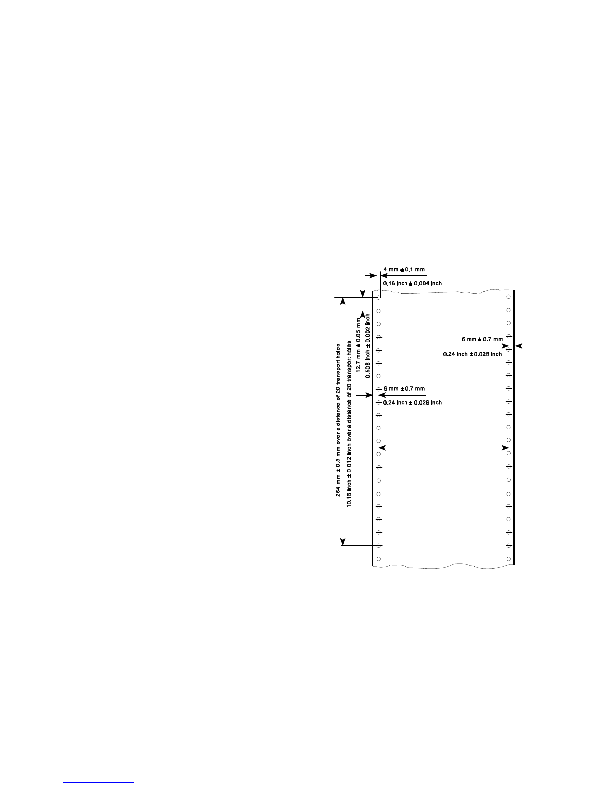
Paper Specification Paper Specification
9-3 9-4
9.4.1 General Guidelines S Transport holes
S Quality
The printer works best with high-quality media. Quality fanfold media for the Note: All measurements conditioned at 23E C (68° F) and 50% RH
laser printer is characterized by uniform physical properties, freedom from
dust and lint, accurate fold, and proper packaging. Proper packaging
protects media from moisture and physical damage.
Avoid paper with curled or bent edges, spots, dust or lint, wrinkling, or
inaccurate size. All these characteristics can cause misfeeding, jamming
premature wear out of printer parts, or unsatisfactory print quality.
S Basis weight
Basis weight (also called grammage) is an important charactaristics of
paper. Paper that is too light or too heavy can cause misfeeds, misstacking,
paper jams, poor image quality, or excessive mechanical wear out in the
printer.
The range of paper weight is from 64 to 155 g/m² ± 5% (17 to 41 lb).
The left centre line of the transport holes
must be parallel to the left centre line.
Tolerance of ± 0.15 mm (0.006 inch)
Page 71

Paper Specification Paper Specification
9-5 9-6
S Perforation 9.4.2 Typical Paper Properties for Laser Printers
Note: All measurements conditioned at 23E C (68° F) and 50% RH
No cut in crossing area!
No cut through the edges!
Description Specifications Applicable
Standard /
Method
curl 5mm (0.2 inch);no diagonal curl at
conditioned (23 ± 2)E C and
(15 ± 5) % RH
stability of maximum 0.8%
dimension cross in heat chamber at 110E C for
to paper path 20 minutes
electrical surface 10 to 10 ohms/square inch PTS-P: 101/84
resistivity (conditioned at 23E C and 50% RH)
8 10
electrical volume < 10 ohms/square inch DIN 53 482
resistivity (conditioned at 23E C and 50% RH)
10
high-temperature < 0.4 % DIN 54 354
stability
raise dust no loose parts; paper should be DIN 53 109
free from dust
fusing must not scorch, melt, offset, or FOGRA-Method
compatibility release hazardous emissions when
heated to 190E C (395E F) for
nearly 0.1 second
Page 72

Paper Specification Paper Specification
9-7 9-8
9.4.3 Paper/Form Properties
Description Specifications Applicable
Standard / Method
basic weight 64 to 155 g/m² ± 5% DIN EN ISO 536 maximum: 16 inch
(17 to 41 lb) Printer
condition no callous, folds, holes, no
raised parts
relative humidity (40 ± 7) % at (21 ± 2)E C DIN EN ISO 287
specific volume 1.3 ± 0.2 cm³/g DIN EN ISO 438
arch maximum 5 mm DIN 6724
bendingforce minimum 0.1 Nmm DIN 53 121
humidity stretching for every 10% difference of DIN 53 130
humidity between 40 and 60%
length maximum 0.04%
cross maximum 0.2%
smoothness by minimum 18s; maximum 30s DIN 53 103
Bekk
porosity by 5.3 ± 2.5 Fm / (Pa × s) DIN 53 120
Bendtsen
humidity entering 23 ± 5 g/m² DIN 53 132
(Cobb 60)
pH-value > 5.0 DIN 53 124
opacity > 75 % DIN 53 146
paper width minimum: 4 inch (101.6 mm)
maximum: 10 inch (254 mm)
Description Specifications Applicable
Standard / Method
Paper length:
Printer with iPS minimum: 8 inch
without iPS minimum: 3 inch
maximum: 20 inch
relative humidity (40 ± 7) % at (21 ± 2)E C DIN EN ISO 287
difference maximum 10% RH
between humidity
of paper and
ambiance
difference maximum ± 2E C
between paper
and room
temperature
batch incline 12 mm for a pile of paper
50 mm high
distance between 6.00 mm ± 0.7 mm DIN EN ISO 2784
centre of transport
hole and paper
edge
diameter of 4.00 mm ± 0.1 mm DIN EN ISO 2784
transport holes
breaking strength 16 ± 2 N / cm
of perforation
Page 73

Paper Specification Paper Specification
9-9 9-10
9.4.4 Label Carrier Properties 9.4.5 Label Properties
Description Specifications Applicable Description Specifications Applicable
Standard / Method Standard /
specific (1.3 ± 0.2) cm³/g DIN EN ISO 438
volume condition no callous, folds, holes, no raised DIN 6730
arch maximum 5 mm DIN 6724
break stability vertical minimum 85 N DIN 53 112
horizontal minimum 40 N arch maximum 5 mm DIN 6724
crack stability minimum 150 kPa DIN EN ISO 2758 break stability vertical minimum 65 N DIN 53 112
roughness by 200 to 500 ml/mim DIN EN ISO 2494
Bendtsen roughness by 200 to 500 ml/mim DIN EN ISO 2494
bending force minimum 0.1 Nmm DIN 53 121
measure distance: bending force minimum 0.1 Nmm DIN 53 121
10 mm measure
bending angle distance:
12E 10 mm
humidity for every 10% difference of DIN 53 130
stretching humidity between 40 and 60%
length maximum 0.04% humidity for every 10% difference of DIN 53 130
cross maximum 0.2% stretching humidity between 40 and 60%
electrical 10 to 10 ohms/square inch PTS-P: 101/84
surface (conditioned at 23E C and 50% RH)
resistivity electrical surface 10 to 10 ohms/square inch PTS-P: 101/84
8 10
Method
parts
specific volume (1.3 ± 0.2) cm³/g DIN EN ISO 438
horizontal minimum 40 N
Bendtsen
bending angle
12E
length maximum 0.04%
cross maximum 0.2%
resistivity (conditioned at 23E C and 50% RH)
8 10
electrical volume < 10 ohms/square inch DIN 53 482
resistivity (conditioned at 23E C and 50% RH)
10
relative humidity (40 ± 7) % at (21 ± 2)E C DIN EN ISO 287
Page 74

Paper Specification
Description Specifications Applicable
Standard /
Method
9-11 9-12
difference maximum 10% RH
between
humidity of paper
and ambiance
difference maximum ± 2E C
between paper
and room
temperature
curl 5mm (0.2 inch); no diagonal curl at DIN 6724
conditioned (23 ± 2)E C and
(50 ± 5) % RH
stability of maximum 0.8%
dimension cross in heat chamber at 110E C for
to paper path 20 minutes
removable (2.0 ± 0.2) cN / 10 mm FINAT FTM 3
stability
high-temperature < 0.4 % DIN 54 354
stability no dropping of glue particles
Note: Cutting through a sticky label leaves glue on the blade, leading to
problems with the cutting device. Small parts of a cut through label could
detach from its paper and block the cutter or the paper path completely.
Page 75

Maintenance / Logbook
10-1 10-2
10 Maintenance / Logbook
Exchange of consumables
10.1 Toner Kit
Toner-Kit Toner Waste Cleaner
Section 5.1 refilled Toner Felt of the
Bottle Fuser
replaced replaced
Date Machine Counter yes no yes no yes no
(see Self Test)
Toner-Kit Toner Waste Cleaner
Section 5.1 refilled Toner Felt of the
Bottle Fuser
replaced replaced
Date Machine Counter yes no yes no yes no
(see Self Test)
Page 76

Maintenance / Logbook Maintenance / Logbook
10-3 10-4
10.2 OPC-Drum 10.3 Developer Unit
OPC-Drum replaced Transfer Corona Remarks Developer Unit replaced Starter-Toner Ozon Filter
Section. 5.2 wire Section 5.3 filled in ? replaced
cleaned
Date Machine Counter yes no (see Self Test)
(see Self Test)
Date Machine Counter yes no yes no
Page 77

Maintenance / Logbook Maintenance / Logbook
10-5 10-6
10.4 Fuser Unit 10.5 Inspection Report
Replacement of the Fuser Unit Remarks Date Name Error Status Service Activity
by a Service Technican (Section
5.4)
Date Machine Counter
(see Self Test)
Page 78

Maintenance / Logbook Maintenance / Logbook
10-7 10-8
10.6 Customer Remarks
Page 79

Appendix A Programming Guide
A-1 A-2
Appendix A Programming Guide A-1 Support of Printer Specific Features and Functions
The printer supports the PJL Printer Job Language and PCL5 Printer Language. Language commands. The following hints show in combination with application
All the printer´s unique feature and functions which can be controlled by the
application software via PJL or PCL5 commands. A-1.1 Profiles
Among those functions are the following: The printer can store 10 separate printer configuration settings called Profile.
S Job Control Support using profiles see paragraph A-1.1 One profile should be used for one specific application. This application requires
S Support of various paper sizes see paragraph A-1.2 a special setting for the paper format, the paper path, fuser temperature...
S Support of semigraphics for application under SAP/R3 see paragraph A-1.3 In an system environment where the application can not use a driver to select
S Euro symbol support for a restricted number of code pages the application specific parameters a profile can be selected with a specific PJL
and type faces see paragraph A-1.4 command which has to be send to the printer before sending the application file.
S Support of Logical and Physical Pages see paragraph A-1.5 Example:
S Printer set up configuration via PJL commands see chapter A-2 ESC%-12345X@PJL DEFAULT PROFILE = 5
S Printer set up configuration via PCL5 commands see chapter A-3 ESC%-12345X
S Support of 13 resident Barcodes by privat PCL5 commands see chapter A-5
The features described below refer to the Firmware Revision V2.xx of the
printer. The printer supports paper format A4, Letter and CUSTOM.
Note: For more information regarding PJL and PCL5 programming please refer These PJL commands have to be send to the printer before sending the data of
to the the application file.
S PJL Printer Job Language (5961-0704) In the following Example (with PJL SET) the paper format selection is only valid
S PCL5 Printer Language Technical Reference Manual (5961-0509) for one PCL application file. After a power off or PJL reset the USER DEFAULT
published by Hewlett-Packard Company. environment variables are valid:
®
The Fanfold Laser Printer provides programming support of Printer Specific
Features
and Functions. These Functions are implemented with special Printer Job
examples how to use and program these functions:
A-1.2 Paper Size Select
With paper format CUSTOM the page size can be set by PJL commands.
ESC%-12345X@PJL SET PAPER = CUSTOM
@PJL SET PAGELENGTH = 11 1/3
@PJL SET IMAGEWIDTH = 7.15
@PJL ENTER LANGUAGE = PCL
ESCE......PCL application file.....ESCE
Page 80

Appendix A Programming Guide Appendix A Programming Guide
A-3 A-4
A-1.3 Semigraphics Support under SAP R/3 A-1.5 Support of Logical and Physical Pages
To increse the printer performance when the printer is running under SAP R/3
Psi provides printer specific SAP R/3 device types. These device types make
use of the special semigraphic line draw elements. (see chapter A-4 Support of
Semigraphics for SAP/R3)
The SAP R/3 device type ZPSI2024.PRI including installation description can
be downloaded from the Psi homepage:
www.psi-si.de
A-1.4 EURO Symbol Support
The printer supports printing of the EURO symbol as printer resident character
within the following code tables (see also Appendix B):
S ISO 8859 / 15 LATIN 9
S PC - 858 Multilingual
S SYMBOL
S WINDINGS
Note: The EURO symbol is not supported in combination with all printer
typefaces.
One Physical page can be spitt into Logical pages by the parameter
LENGTHFACTOR.
The Pagelength must be configured or programmed according to the physical
length of one page to enshure proper function of the attached stacker. Up to 20
logical pages can be placed on one physical page. The lengthlimit for an
attached stacker (minimum pagelength is 8 inch) is only valid for the physical
pagelength. Two Logical pages of 6 inch can be printed on physical paper with
12 inch length with LENGTHFACTOR = 2.
The following example shows the PJL commands for an application with
imagewidth = 8.5 inch and a logical pagelength of 3 inch to be printed on a
physical pagelength of 12 inch:
ESC%-12345X@PJL SET PAPER = CUSTOM
@PJL SET IMAGEWIDTH = 8.5
@PJL SET PAGELENGTH = 12
@PJL SET LENGTHFACTOR = 4
@PJL ENTER LANGUAGE = PCL
ESC E....PCL file page 1....FF....page 2....FF
....page3....FF ESC E....
Note: PJL or PCL commands which are related to the physical page like paper
source, number of copies, and cut force a feeding of the paper to the top
of the next physical page.
These settings are valid until a PJL RESET condition. ( PJL SET
command)
Page 81

Appendix A Programming Guide Appendix A Programming Guide
A-5 A-6
A-1.7 Conventions A-2 List of Supported PJL Control Functions
The following conventions are used in the command listings: The Fanfold Laser Printer provides limited support of Printer Job
ESC Escape (1/B), introduces an escape sequence
@ Introduce a PJL command
P1 Numeric parameter, or number of units that specify a distance or
quantity pertaining to the escape sequence, control function or
control string. Accepted values are 0...9999.
If the parameter is in normal notation like "200" the programming
in hex-code is according to a ASCII table. ("200" = 32,30,30 in
hex).
8 or <SP> Spaces may appear between characters in sequence for clarity;
they are not part of the format. A Space character (hex 20) is
indicated by the grafik symbol 8 or by <SP>.
<CR> Carriage Return (hex 0D)
<LF> Line Feed (hex 0A)
Language (PJL). PJL topics which are described in this chapter are:
Basic Rules for PJL Programming
S PJL Environments
S List of supported PJL Commands
S List of supported PJL Variables and Values
S List of supported PJL Variables and Values for PCL Personality
For more information on topics covered in this section, please refer to the
Printer Job Language Technical Reference Manual by Hewlett-Packard, Inc.
A-2.1 Basic Rules for PJL Programming
Printer Job Language (PJL) command sequences are used to define all specific
parameters for one print job. PJL commands provide the following major
functions:
S Printer language switching between jobs
S Job separation
S Printer configuration
S Status readback from the printer to the host
At the beginning of every print job the UEL command ( ESC % - 1 2 3 4 5 X ) is
used to switch from the print emulation (PCL, Postscript, HEXDUMP...) to the
PJL command level.
A-2.1.1 PJL Syntax Rules
S Use only uppercase characters
S All parts of a PJL command line must be separarted by a <SP> (Space)
S Every PJL command line must start with the prefix @PJL.
S Every PJL command line must end with <LF> (Line Feed)
Sample of typical PJL command line:
@PJL <SP>DEFAULT<SP> LPARM : PCL <SP> PTSIZE = 12<LF>
PREFIX <SP> COMMAND <SP> Com. Modifier : Value <SP> Variable = Value<LF>
Note: The fist PJL command after the UEL must start with @PJL....! (no <SP>)
Page 82

Factory Default
Environment
@PJL INITIALIZE
Operator
Panel or
@PJL
DEFAULT
User Default
Environment
PJL Current
Environment
ESC E or
@ PJL ENTER LANGUAGE
or any language switch via
operator panel
@PJL SET
PCL
command
@PJL RESET or
PJL JOB or EOJ or
PCL UEL
Modified Print
Environment
Appendix A Programming Guide Appendix A Programming Guide
A-7 A-8
A-2.1.2 PJL Environments A-2.1.3 List of Supported PJL Commands
The factory default is stored in the
flash memory of the printer and can
not be changed by the user
After power on or after RECALL
FACTORY or after @PJL INITIALIZE
the printer default settings are copied
from the Factory Defaults
Environment into the User Default @PJL EOJ [NAME=”job The EOJ command marks the end of the job
Environment name”] which was started with the previous JOB
The User Default Environment Environment to the User Default Environment.
settings are modified using the The JOB and EOJ commands should always
operator panelm keys and/or the be used in pairs. Do not use one without the
@PJL DEFAULT command other.
When a PJL reset occurs, the User
Default Environment settings are
loaded into the PCL Current
Environment
The PCL commands as part of
application data streams changes the
PJL Current Environment settings
using the @PJL SET command
settings
A language reset (ESC E or @PJL
ENTER LANGUAGE) loads the PCL
Current Environment settings into the
Modified Print Environment
PJL COMMAND Description
@PJL COMMENT [”text”] The COMMENT command is used for adding
a line of information or a comment within a set
of PJL commands.
@PJL JOB [NAME= ”text”] Defines the name and pages of a PCL print
[START= #] [END = #] job.
NAME = file name (ASCII text)
START = first page, range 1 to 214783647
END = last page, range 1 to 214783647
command. It resets the PJL Current
@PJL ENTER LANGUAGE Supported personality options are
= personality PCL , HEXDUMP
@PJL RESET The RESET command resets the PJL Current
Environment variables to their User Default
Environment values (see Figure x.y for a
descriptions of PJL Environments).
@PJL INITIALIZE The INITIALIZE command resets the PJL
Current Environment and the User Default
Environment variables to their Factory Default
Environment values.
@PJL DEFAULT The DEFAULT command sets the User
[LPARM : personality] Default Environment value for a specified
Variable = value variable.
Personality : PCL, HEXDUMP
For supported variables and values see table:
A-2.1.4 PJL Variables and Values
Page 83

Appendix A Programming Guide Appendix A Programming Guide
A-9 A-10
PJL COMMAND (cont.) Description
@PJL SET The SET command allows the user to change
[LPARM : personality] the value of PJL Current variables for the
Variable = value length of a PJL job, or until a PJL reset
condition returns the value to ist default.
Personality : PCL, HEXDUMP
For supported variablews and values see
table: A-2.1.4 PJL Variables and Values
@PJL RDYMSG ["text of Display a message in the 1 line of the
message”] printer´s operator panel
st
The message length is at max. 16 characters
The printer remains online
@PJL RDYMSG ["”] Clear the message on the printer´s operator
panel
@PJL OPMSG ["text of Display the message in the 1 line of the
message”] printer´s operator panel
st
The message length is at max. 16 characters
The printer gets off line
After prompting of this status by pushing the
offline/online button, the printer goes ONLINE
again
A-2.1.4 List of Supported PJL Variables and Values
The following variables can be programmed by the PJL commands:
S @PJL SET ”variable” = ”value”
S @PJL DEFAULT ”variable” = ”value”
PJL VARIABLE VALUES
PROFILE 1, 2, 3, ....., 10
PAPER A4, LETTER, CUSTOM
PAGELENGTH 3, 3 1/8, ....., 20
in steps of 1/4, 1/6, or 1/8 inch
Note: value 3 1/6 programming is 3<SP>1/6
LENGTHFACTOR 1, 2, 3, ...., 20
IMAGEWIDTH 0.5, 0.55, ....., 8.25 inch
in steps of 0.05 inch
LENGTHFACTOR 1, 2, 3, ...., 20
ORIENTATION PORTRAIT, LANDSCAPE
LANDSCAPEMODE REVERSE, PCLCOMPATIBLE
ORIENTATIONMODE FIXED, AUTOMATIC
PAPEREXTENDED NO, YES
Page 84

Appendix A Programming Guide Appendix A Programming Guide
A-11 A-12
PJL VARIABLE (cont.) VALUES
PAPERSELECT RECOGNIZE, ONLYPJL, IGNORE
FUSERTEMP 165 to 185 in steps of 5
VERSHIFT -50, -49, ....., -1, 0, 1, 2, ....., 50
HORSHIFT -50, -49, ....., -1, 0, 1, 2, ....., 50
PERSONALITY PCL, HEXDUMP
AUTOFORMFEED OFF, 1, 2, ....., 120
PAPERRETRACT ON, OFF
Note: All parameter which can be programmed with PJL Variables can also be
configured by the Operator Panel of the printer.
For detailled description of parameters see chapter 4 Explanation of
Individual Menu Items
The following variables can be programmed by the PJL command:
S @PJL DEFAULT ”variable” = ”value”
PJL VARIABLE VALUES
POWERSAVE OFF, 15, 30, 45, 60
ALARMBELL ON, OFF
LANG ENGLISH, GERMAN
MENUACCESS ALL, PROFILESONLY, NONE
Note: These variables can not be used by the PJL COMMAND SET.
For detailled description of parameters see Chapter 4 Explanation of
Individual Menu Items
Page 85

Appendix A Programming Guide Appendix A Programming Guide
A-13 A-14
A-2.1.5 List of Supported PJL Variables and Values for PCL Personality A-3 List of Supported PCL5 Control Functions
The following variables can be programmed by the PJL commands:
S @PJL SET LPARM : PCL ”variable” = ”value”
S @PJL DEFAULT LPARM : PCL ”variable” = ”value”
PJL VARIABLE VALUES
FONTNUMBER 1, 2, 3, ....., 54
PITCH 0.44, ....., 99.99 (in steps of 0.01)
PTSIZE 4.00, 4.25, ....., 99.75 (in steps of 0.25)
SYMSET ROMAN8, ISOL1, ISOL2, ISOL5, ISOL9, PC8,
PC8DN, PC850, PC852, PC858, PC8TK,
WINL1, WINL2, WINL5, DESKTOP,
PSTEXT,VNINTL, VNUS, MSPUBL, MATH8,
PSMATH, VNMATH, PIFONT, LEGAL, ISO4,
ISO6, ISO11, ISO15, ISO17, ISO21, ISO60,
ISO69, WIN30
LINESPACING 1, 2, 3, ....., 48
TOPMARGIN 0, 1, 2, ....., 999
LEFTMARGIN 0, 1, 2, ....., 999
RIGHTMARGIN 0, 1, 2, ....., 999, MAXIMUM
TEXTLENGTH 0, 1, 2, ....., 999
PERFORATIONSKIP OFF, ON
Note: All parameter which can be programmed with PJL Variables can also be
configured by the Operator Panel of the printer.
For detailled description of parameters see Chapter 4 Explanation of
Individual Menu Items
A-3.1 Job Control Commands
JOB CONTROL Description
COMMANDS
ESC % - 12345 X Universal Exit / Start of PJL
Change to PJL Language Interpretation Mode
Reset the printer like performing a Reset
command
Print all data received before the UEL
command
ESC E Reset
Reset to PJL Current Environment
Printing of any partial pages
Deleting of all temporary download resources,
as macros, fonts, and patterns
ESC & ll # X Number of Copies
Number of printed copies for each page
ESC & ll # U Left Offset Registration
Position of the logical page across width of the
physical page
ESC & ll # Z Top Offset Registration
Position of the logical page along length of the
physical page
ESC & u # D Unit of Measure
Measure for PCL unit cursor movements
Page 86

Appendix A Programming Guide Appendix A Programming Guide
A-15 A-16
A-3.2 Page Control Commands
PAGE CONTROL Description
COMMANDS
ESC & ll # A Page Size
(Private Command) # = 101 : Custom
Definition of the paper size and in turn of the
logical page size.
Parameters:
# = 2 : Letter
# = 26 : A4
ESC & ll # O Orientation
Different rotations of the logical page
# = 0 : Portrait
# = 1 : Landscape
# = 2 : Reverse Portrait
# = 3 : Reverse Landscape
ESC & a # P Print Direction
Rotation of the page coordinate system related
to the current position in steps of 90E
ESC & a # L Left Margin
Setting to the left edge of the page (columns)
ESC & a # M Right Margin
Setting to the right edge of the page (columns)
PAGE CONTROL Description
COMMANDS (cont.)
ESC 9 Clear Horizontal Margins
Resetting of the right and left margin
ESC & ll # E Top Margin
Setting top of the text area in lines
ESC & ll # F Text Length
Number of printing lines per page
Setting of the bottom margin
ESC & ll # L Perforation Skip
# = 0 : Disable
# = 1 : Enable
ESC & k # H Horizontal Motion Index
Width of the columns where # (x 1/120 inch)
ESC & ll # C Vertical Motion Index
Height of rows where # (x 1/48 inch)
ESC & ll # D Line Spacing
Number of lines printed per inch
# = 1, 2, 3, ....., 48
Page 87

Appendix A Programming Guide Appendix A Programming Guide
A-17 A-18
A-3.3 Cursor Positioning Commands
CURSOR POSITIONING Description
COMMANDS
ESC & a # C Horizontal Position in Columns # = 1 : CR = CR+LF, LF = LF, FF = FF
ESC * p # X Horizontal Position in PCL Units
ESC & a # H Horizontal Position in Decipoints
ESC & a # R Vertical Position in Rows
ESC * p # Y Vertical Position in PCL Units
ESC & a # V Vertical Position in Decipoints
ESC = Half Line Feed
ESC & k # G Line Termination
ESC & f # S Push / Pop Cursor Position
ESC & a # C Horizontal Position in Columns
ESC * p # X Horizontal Position in PCL Units
ESC & a # H Horizontal Position in Decipoints
ESC & a # R Vertical Position in Rows
ESC * p # Y Vertical Position in PCL Units
ESC & a # V Vertical Position in Decipoints
ESC = Half Line Feed
CURSOR POSITIONING Description
COMMANDS (cont.)
ESC & k # G Line Termination
# = 0 : CR = CR, LF = LF, FF = FF
# = 2 : CR = CR, LF = CR+LF, FF = CR+FF
# = 3 : CR = CR+LF, LF = CR+LF,
FF = CR+FF
ESC & f # S Push / Pop Cursor Position
# = 0 : Push (Store)
# = 0 : Pop (Recall)
ESC & s # C End-Of- Line Wrap
# = 0 : Enable
# = 1 : Disable
CR (hex 0D) Carriage Return
SP (hex 20) Space
BS (hex 08) Backspace
HT (hex 09) Horizontal Tab
LF (hex 0A) Line Feed
FF (hex 0C) Form Feed
Page 88

Appendix A Programming Guide Appendix A Programming Guide
A-19 A-20
A-3.4 Font Selection Commands
FONT SELECTION Description
COMMANDS
ESC ( ID Symbol Set , primary *)
ID = Code for Symbol Set, see Chapter 4
Explanation of Individual Items and here
point SYMBOL SETS or a Printout of PCL
TYPEFACE LIST
ESC ( s # P Spacing, primary *)
# = 0 : Fixed Spacing
# = 1 : Proportional Spacing
ESC ( s # H Pitch, primary *)
# = Number of character per inch
ESC ( s # V Height, primary *)
# = Character height in point
ESC ( s # S Style, primary *)
# = 0 : Upright
# = 1 : Italic
ESC ( s # B Stroke Weight, primary *)
# = 0 : Medium
# = 3 : Bold
ESC ( s # T Typeface, primary *)
# = Code number for Typeface, see
Printout of PCL TYPEFACE LIST
ESC ( s # X Font Selection by ID #, primary *)
ESC ( 3 @ Select Default Font as primary *)
*) All commands for primary with ?(? parenthesis can be used for
secondary with ?)? parenthesis
A-3.5 Font Management Commands
FONT MANAGEMENT Description
COMMANDS
ESC & d # D Enable Underline
# = 0 : Fixed position
# = 3 : Floating position
ESC & d @ Disable Underline
ESC & p # X [data] Transparent Print Data
ESC * c # D Assign Font ID #
ESC * c # F Font Control
ESC * c # R User Defined Symbol Set ID Code
ESC ( f # W [data] User Defined Symbol Set Data
ESC * c # S User Defined Symbol Set Control
ESC ) s # W [data] Soft Font Descriptor
ESC * c # E Soft Font Character Code
ESC ( s # W [data] Soft Font Download Character
ESC Y Display Functions Mode On
ESC Z Display Functions Mode Off
Note: For detailled informations see PCL 5 Technical Reference Manual from
HP
Page 89

Appendix A Programming Guide Appendix A Programming Guide
A-21 A-22
A-3.6 Macro Control Commands A-3.7 Graphic Commands
MACRO CONTROL Description
COMMANDS
ESC & f # Y Macro ID
ESC & f # X Macro Control
# = 0 : Start macro definition (last ID
specified)
# = 1 : Stop macro definition
# = 2 : Execute macro (last ID specified)
# = 3 : Call macro (last ID specified)
# = 4 : Enable macro for automatic
overlay (last ID specified)
# = 5 : Disable automatic overlay
# = 6 : Delete all macros
# = 7 : Delete all temporary macros
# = 8 : Delete macro (last ID specified)
# = 9 : Make macro temporary
(last ID specified)
# = 10 : Make marco permanent
(last ID specified)
Note: For detailled informations see PCL 5 Technical Reference Manual from
HP
GRAPHIC Description
COMMANDS
ESC * v # N Source Transparency Mode
ESC * v # O Pattern Transparency Mode
ESC * c # G Area Fill ID
ESC * v # T Select Current Pattern
ESC * c # W [data] Define User Defined Pattern
ESC * p # R Set Pattern Reference Point
ESC * c # Q User Defined Pattern Control
ESC * t # R Raster Graphic Resolution
ESC * r # F Raster Graphic Presentation
ESC * r # T Raster Graphic Heigth
ESC * r # S Raster Graphic Width
ESC * r # A Start Raster Graphics
ESC * b # Y Raster Graphic Y Offset
ESC * b # M Raster Graphic Compression Mode
ESC * b # W [data] Transfer Raster Graphic Data
ESC * B or ESC * C End of Raster Graphic
ESC * c # A Horizontal Rectangle Size, PCL Units
ESC * c # H Horizontal Rectangle Size, Decipoint
ESC * c # B Vertical Rectangle Size, PCL Units
ESC * c # V Vertical Rectangle Size, Decipoints
ESC * c # G Pattern ID for Area Fill
ESC * c # P Fill Rectangle Area
ESC * c # X HPGL Horizontal Picture Frame Size
ESC * c # Y HPGL Vertical Picture Frame Size
ESC * c 0 T HPGL Picture Frame Anchor Point
ESC * c # K HPGL Horizontal Plot Size
ESC * c # L HPGL Vertical Plot Size
ESC % # B Enter HPGL Mode
ESC % # A Return from HPGL to PCL Mode
Note: For detailled informations see HP PCL 5 Technical Reference Manual.
Page 90

Appendix A Programming Guide Appendix A Programming Guide
A-23 A-24
A-4 Support of Semigraphics for SAP/R3 A-5 Barcode Programming
Semigraphical Symbols in Symbol Set ISO 8859/1 and PC-8 A-5.1 Resident Barcode Font Code 39 HP Compatible
The symbol set ISO 8859/1 and PC-8 contain 11 semigraphical symbols to The barcode Code 39 is integrated as two bitmapped fonts into the Operating
optimally support line drawing functions in SAP/R3 applications: System for the printer as resident printer font. This bitmapped fonts can be used
Position in Character Position in
ISO 8859/1 PC-8 PC-8
9/0 3 C/5
9/1 ) C/4
9/2 * B/3
9/3 + D/A
9/4 , B/F
9/5 . C/0
9/6 - D/0
9/7 / C/3
9/8 1 B/4
9/9 0 C/2
9/A 2 C/1
The symbols are selected from the symbol set table with the specified typeface
4099 (courier) with fix spacing and pitch, default style and default stroke weight.
ESC(ON(s0p16.67h0s0b4099T
compatible to the cartridge implementation from Hewlett Packard Bar
Code & More for HP laser printers.
The printer resident barcode font Code39 can be selected either from the
operator panel of the printer as internal font number 52 and 53 (for progrmming
detail see PCL Typeface List) or by PCL command with the following
parameters:
S symbol set 0Y pitch 8.17 typeface 0 (line printer) or
S symbol set 0Y pitch 4.71 typeface 0 (line printer)
S
The printer offers variety set of resident Barcodes which can be addressed by
means of additional PCL 5 control sequences.
This HP barcode fonts can be used like any other bitmapped font in the PCL5
emulation. Position and rotation is possible by PCL5 commands.
Note: Horizontal scalling is only possible to the values 8.17 or 4.71 CPI.
Vertical enlargement is possible by printing more lines.
Print sample:
Page 91

Appendix A Programming Guide Appendix A Programming Guide
A-25 A-26
A-5.2 Resident Barcode Controlled by Private Command Sequence A-5.2.1 Programming
Generally barcodes are programmed in three steps: sequences added to the PCL5 emulation.
1. Select a barcode type and define the barcode specific parameter set of The print position and print orientation of a barcode is controlled by standard
S height PCL5 commands.
S module width
S ratio of bars to spaces S Barcode print position
S text control Printing of any barcode starts at the current actual cursor position. The
2. Define barcode print position and print orientation position can be set with any standard PCL5 cursor movement command.
3. Print the barcode by sending the barcode data command Moving the cursor with printed characters, spaces and carriage return and
Note: For every barcode an individual set of parameters (height, module width, Setting the cursor to an absolute or relative position in PCL units is the best
ratio, text control) is stored. The default values (see table on page A-29) way to position a barcode:
of these parameters are activated with the first selection of a barcode
type. ESC * p P1 X absolute horizontal position to P1
Programming a new parameter modifies only the value of the actual ESC * p + P1 X relative horizontal position P1 to the left
selected barcode type. The value is applied until it is overwritten by a ESC * p - P1 X relative horizontal position P1 to the right
new value or the printer is switched off. (Barcode parameters are not ESC * p P1 Y absolute vertical position to P1
stored in the printer environment !) ESC * p + P1 Y relative vertical position P1 down
S The Resident Barcodes are:
Code 39, Note: S The barcode REFERENCE POSITION is the left upper edge except
2 of 5 industrial, for Postnet where the reference position is the character baseline.
2 of 5 interleaved,
EAN 8 SC2, EAN 8 SC6, EAN 8 SC9, S The cursor position is not changed after printing the barcode.The
EAN 13 SC2, EAN 13 SC6, EAN 13 SC9, cursor must be set to a new position for the next printable character.
UPC-A SC2, UPC-A SC6, UPC-A SC9,
UPC-E SC2, UPC-E SC6, UPC-E SC9, S One PCL unit is the unit of measure for cursor movements. The
Codabar, default value is 300 units per inch.
MSI,
Code 93,
Postnet, S Barcode print orientation
Code 128, and Barcodes are printable in all four print directions, selectable with the
RM4SCC/KIX. following PCL5 command:
Programming of the resident barcodes is achieved by means of six new control
line feed is the simplest possibility.
ESC * p - P1 Y relative vertical position P1 up
ESC & a P1 P P1 = 0, 90, 180, 270 default = 0°
Page 92

Appendix A Programming Guide Appendix A Programming Guide
A-27 A-28
S Barcode type S Barcode height
This command selects a barcode type: This command defines the height of the actual selected barcode:
ESC * z P1 V default = 0 ESC * z P1 H P1 = height in PCL units
P1 = 0 Code 39 For every barcode type an individual value is stored. The default height value
P1 = 1 2 of 5 industrial for barcode is 0.5 inch (P1 = 150) except EAN, UPC and Postnet.
P1 = 2 reserved The default height for EAN and UPC is defined with the scaling factor SC 2, 6
P1 = 3 reserved or 9. The height of Postnet is fixed.
P1 = 4 2 of 5 interleaved Barcode height values are selectable in the range from 0.1 inch (P1 = 30) to
P1 = 102 EAN 8 SC2 10 inch (P1 = 3000).
P1 = 106 EAN 8 SC6
P1 = 109 EAN 8 SC9 Note: One PCL unit is the PCL scaling unit. Default is 300 units per inch.
P1 = 122 EAN 13 SC2
P1 = 126 EAN 13 SC6 S Barcode data
P1 = 129 EAN 13 SC9 This command specifies the barcode data field. Two command formats are
P1 = 142 UPC-A SC2 supported. The first format is conforming to earlier PCL3 commands and
P1 = 146 UPC-A SC6 does not report the number of data bytes in front of the data field:
P1 = 149 UPC-A SC9
P1 = 162 UPC-E SC2 ESC * z < data > Z data = barcode data field
P1 = 166 UPC-E SC6
P1 = 169 UPC-E SC9 The barcode data are enclosed in the two brackets. If the right bracket itself
P1 = 180 Codabar is part of the data field it has to be sent twice.
P1 = 181 MSI
P1 = 188 Code 93 The second format is according to typical PCL5 commands. The number of
P1 = 200 Postnet bytes in the data field is indicated before sending the data:
P1 = 210 Code 128
P1 = 220 RM4SCC/KIX ESC * z P1 Z data P1 = number of bytes in the barcode field data
Note: EAN and UPC code selection supports ADD2 and ADD5 barcode type, otherwise the command is ignored.
extensions by sending those additional digits.
Note: The number of barcode data bytes must correspond to the selected
Page 93

Appendix A Programming Guide Appendix A Programming Guide
A-29 A-30
S Barcode text control S Barcode ratio
This command controls the optional printing of barcode data as an added text This command selects one of the available ratios between wide and narrow
string. bars (spaces).
ESC * z P1 Q
P1 = 0 disable text
P1 = 1 text above barcode with OCR-B font
P1 = 2 text below barcode with OCR-B font (default)
P1 = 3 text above barcode with actual selected font
P1 = 4 text below barcode with actual selected font
The text string is centred to the printed barcode.
Note: S For EAN code with OCR-B font the pitch is not 10 CPI.
S For actual fonts the vertical distance between barcode and text is
equal to the maximum bar width.The programmer has to ensure that
the actual selected font is adequate to be printed in combination
with the barcode.
S Barcode module width
Horizontal scaling of the barcode is selectable by the module width.
This parameter defines the width of the narrow bar in PCL units.
ESC * z P1 S P1 = module width in PCL units
Value range is from 1 to 32,767. The default values for the different barcode
are described in the table on the next page.
Note: For barcode types EAN and UPC the predefined values given with the
scaling factor (see table) must not be modified.
For Postnet and KIX code the module width is fixed.
ESC * z P1 O P1 = 2.0 ; 2.5 ; 3.0 ; default is 2.5
Note: This command is not applicable to all barcodes; refer to table below.
Default values for module width and ratio:
Bar code Module width Ratio
code No. type
default variable default variable
1)
0 Code 39 6 yes 2.5 yes
1 2 of 5 industrial 6 yes 2.5 yes
4 2 of 5 interleaved 6 yes 2.5 yes
102 EAN 8 SC 2 4 yes *) fixed no
106 EAN 8 SC 6 6 yes *) fixed no
109 EAN 8 SC 9 8 yes *) fixed no
122 EAN 13 SC 2 4 yes *) fixed no
126 EAN 13 SC 6 6 yes *) fixed no
129 EAN 13 SC 9 8 yes *) fixed no
142 UPC - A SC 2 4 yes *) fixed no
146 UPC - A SC 6 6 yes *) fixed no
149 UPC - A SC 9 8 yes *) fixed no
162 UPC - E SC 2 4 yes *) fixed no
166 UPC - E SC 6 6 yes *) fixed no
169 UPC - E SC 9 8 yes *) fixed no
180 Codabar 6 yes 2.5 yes
181 MSI 6 yes 2.5 yes
188 Code 93 6 yes fixed no
200 Postnet fixed no fixed no
210 Code 128 6 no fixed no
220 RM4SCC/KIX fixed no fixed no
in / inch
1) 1
300
*) for optimum readability module width should not be changed
Page 94

Appendix A Programming Guide Appendix A Programming Guide
A-31 A-32
S Start and Stop characters A-5.3 Barcode Programming Examples
For barcode types EAN, UPC, Code 93, Code 128 and Postnet the printer
automatically adds start and stop characters. S Example for Code 39
For barcode type Code 39, 2 of 5 industrial and 2 of 5 interleaved the printer
adds start and stop characters only if they are not generated by the system. type = Code 39: ESC * z 0 V
For barcode type Codabar the application has to generate the start and stop Height = 0.6 inch ESC * z 180 H
characters. text = OCR-B above ESC * z 1 Q
Following start and stop characters are accepted by the printer:
Barcode Type Start Character Stop Character
Code 39 * *
2 of 5 types : ;
Codabar a, b, c, d, A, B, C, D t, n, *, e, A, B, C, D
Note: Following combinations (start / stop) are specified for Codabar, but not
checked by the printer:
(a / t) (b / n) (c / *) (d / e) (A / A) (B / B) (C / C) (D / D)
S Error checking characters
Error checking characters are added by the printer only for barcode types
Code 128, Code 93 and Postnet. For all other barcode types the application
has to generate error checking characters and transmit them to the printer.
S Unprinted areas
To ensure proper readability of a barcode unprinted areas in front and behind
the barcode are required. The printer does not insert these areas itself; the
amount of space has to be calculated by the application.
data = CODE 39 ESC * z < CODE 39 > Z
The HEXDUMP datastream for this example is:
1B 2A 7A 30 56 1B 2A 7A 31 38 30 48 1B 2A 7A 31
51 1B 2A 7A 3C 43 4F 44 45 33 39 3E 5A
Print sample:
S Example for 2 of 5 industrial
type = 2 of 5 industrial: ESC * z 1 V
Height = 0.6 inch ESC * z 180 H
mod. width = 10 PCL units ESC * z 10 S
text = OFF ESC * z 0 Q
data = 1 2 3 ESC * z < 1 2 3 > Z
The HEXDUMP datastream for this example is:
1B 2A 7A 31 56 1B 2A 7A 31 38 30 48 1B 2A 7A 31
30 53 1B 2A 7A 30 51 1B 2A 7A 3C 31 32 33 3E 5A
Print sample:
Page 95

Appendix A Programming Guide Appendix A Programming Guide
A-33 A-34
S Example for 2 of 5 interleaved S Example for EAN 8 SC6 add 2
type = 2 of 5 interleave: ESC * z 4 V
position = X=500; Y=500 ESC * p 5 0 0 x 5 0 0 Y
orientation = 90° ESC & a 9 0 P
text = actual font below ESC * z 4 Q
data = 1 2 3 4 ESC * z < 1 2 3 4 > Z
The HEXDUMP datastream for this example is: The HEXDUMP datastream for this example is:
1B 2A 7A 34 56 1B 2A 70 35 30 30 78 35 30 30 59 1B 2A 7A 31 30 36 56 1B 26 61 32 37 30 50 1B 2A
1B 26 61 39 30 50 1B 2A 7A 34 51 1B 2A 7A 3C 31 7A 34 51 1B 2A 7A 31 30 5A 34 30 31 32 33 34 35
32 33 34 3E 5A 35 31 32
Print sample: Print sample:
S Example for EAN 8 SC2
type =EAN 8 SC2: ESC * z 1 0 2 V
orientation = 270° ESC & a 2 7 0 P
text = OCR-B below ESC * z 2 Q
data = 4 0 1 2 3 4 5 5 ESC * z 8 Z 4 0 1 2 3 4 5 5
The HEXDUMP datastream for this example is:
1B 2A 7A 31 30 32 56 1B 26 61 32 37 30 50 1B 2A
7A 32 51 1B 2A 7A 38 5A 34 30 31 32 33 34 35 35
Print sample:
type =EAN 8 SC6 ESC * z 1 0 6 V
orientation = 270° ESC & a 2 7 0 P
text = actual font below ESC * z 4 Q
data = 4 0 1 2 3 4 5 5 1 2 ESC * z 1 0 Z 4 0 1 2 3 4 5 5 1 2
Page 96

Appendix A Programming Guide Appendix A Programming Guide
A-35 A-36
S Example for EAN 8 SC9 add 5 S Example for EAN 13 SC2
type = EAN 8 SC9: ESC * z 1 0 9 V type =EAN 13 SC2: ESC * z 1 2 2 V
text = OCR-B above ESC * z 1 Q orient. = 180° ESC & a 1 8 0 P
data = 4 0 1 2 3 4 5 5 8 6 1 0 4 ESC * z 1 3 Z 4 0 1 2 3 4 5 5 8 6 1 0 4 text = OCR-B below ESC * z 2 Q
The HEXDUMP datastream for this example is:
1B 2A 7A 31 30 39 56 1B 2A 7A 31 51 1B 2A 7A 31
33 5A 34 30 31 32 33 34 35 35 38 36 31 30 34
Print sample:
data = 4 1 2 3 4 5 6 7 8 9 0 1 8 ESC * z 1 3 Z 4 1 2 3 4 5 6 7 8 9 0 1 8
The HEXDUMP datastream for this example is:
1B 2A 7A 31 32 32 56 1B 26 61 31 38 30 50 1B 2A
7A 32 51 1B 2A 7A 31 33 5A 34 31 32 33 34 35 36
37 38 39 30 31 38
Print sample:
S Example for Codabar
type = Codabar ESC * z 1 8 0 V
ratio = 3.0 ESC * z 3 . 0 O
text = OCR-B below ESC * z 2 Q
data = a 0 1 2 3 4 5 6 7 8 9 t ESC * z 1 2 Z a 0 1 2 3 4 5 6 7 8 9 t
The HEXDUMP datastream for this example is:
1B 2A 7A 31 38 30 56 1B 2A 7A 33 2E 30 4F 1B 2A
7A 32 51 1B 2A 7A 31 32 5A 61 30 31 32 33 34 35
36 37 38 39 74
Print sample:
Page 97

Appendix A Programming Guide Appendix A Programming Guide
A-37 A-38
S Example for Code 128 S Example for POSTNET
act. font = Ribbon SWC 20 Pt ESC ( s 1 p 2 0 v 1 s 0 b 4 1 1 6 T type = POSTNET ESC * z 2 0 0 V
type = Code 128: ESC * z 2 1 0 V data = 123456789 ESC * z < 123456789 > Z
orient. = 90° ESC & a 9 0 P CR LF LF 0D 0A 0A
text = actual font below ESC * z 4 Q Mark Pollmann CR LF Mark Pollmann 0D 0A
data = C o d e 1 2 8 ESC * z < C o d e 1 2 8 > Z 101 Main St CR LF 101 Main St 0D 0A
The HEXDUMP datastream for this example is:
1B 28 73 31 70 32 30 76 31 73 30 62 34 31 31 36
54 1B 2A 7A 32 31 30 56 1B 26 61 39 30 50 1B 2A
7A 34 51 1B 2A 7A 3C 43 6F 64 65 31 32 38 3E 5A
Print sample:
Anytown US Anytown US
The HEXDUMP POSTNET datastream for this example is:
1B 2A 7A 32 30 30 56 1B 2A 7A 3C 31 32 33 34 35
36 37 38 39 3E 5A
Print sample:
Mark Pollmann
101 Main St
Anytown US
S Example for RMS4SCC / KIX
type = KIX ESC * z 2 2 0 V
data = 9 7 2 5 K E 5 6 x 4 3 ESC * z < 9 7 2 5 K E 5 6 x 4 3 > Z
The HEXDUMP datastream for this example is:
1B 2A 7A 32 32 30 56 1B 2A 7A 3C 39 37 32 35 4B
45 35 36 78 34 33 3E 5A
Print sample:
Page 98

B-1 B-2
Appendix B Symbol Sets
SS Roman-8 Display: ROMAN-8 ID Number: 8U SS ISO 8859/1 Latin 1 Display: ISO L1 ID Number: 0N
Appendix B Symbol Sets
Page 99
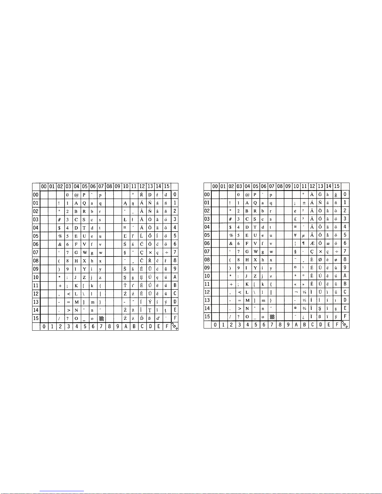
Appendix B Symbol Sets Appendix B Symbol Sets
B-3 B-4
SS ISO 8859/2 Latin 2 Display: ISO L2 ID Number: 2N SS ISO 8859/9 Latin 5 Display: ISO L5 ID Number: 5N
Page 100

Appendix B Symbol Sets Appendix B Symbol Sets
B-5 B-6
SS ISO 8859/15 Latin 9 Display: ISO L9 ID Number: 9N SS PC-8 Code Page 437 Display: PC-8 ID Number: 10U
Note: sign in position A4 (hex)
 Loading...