

PSI FluorPen FP 100, PAR-FluorPen FP 100-MAX-LM, FluorPen FP 100-B, FluorPen FP 100-MAX, FluorPen FP 100-U Operation Manual
...Page 1

FFlluuoorrPPeenn FFPP 110000
SSeerriieess
OOppeerraattiioonn MMaannuuaall
For: FluorPen FP 100
FluorPen FP 100-MAX
PAR-FluorPen FP 100-MAX-LM
FluorPen FP 100-B
FluorPen FP 100-U
FluorPen or PAR-FluorPen
with detachable leafclips
PSI (Photon Systems Instruments), spol. s r.o.
Drasov 470, 664 24 Drasov, Czech Republic
http://www.psi.cz
Page 2

2
Table of Contents
1. Technical Specification ................................................................................................................................................ 3
2. General Information ...................................................................................................................................................... 5
3. List of Equipment............................................................................................................................................................ 8
4. Physical Features ............................................................................................................................................................ 9
5. Accessories .................................................................................................................................................................... 10
6. Operation Instructions .............................................................................................................................................. 12
7. Bluetooth Pairing and Connecting ........................................................................................................................ 20
7.A. General Information .............................................................................................................................................................. 20
7.B. Bluetooth Pairing .................................................................................................................................................................... 21
7.C. Bluetooth Connection ............................................................................................................................................................ 24
8. USB Pairing and Connecting .................................................................................................................................... 26
8.A. General Information .............................................................................................................................................................. 26
8.B. USB Pairing ................................................................................................................................................................................ 26
9. FluorPen Software ...................................................................................................................................................... 27
9.A. Starting up .................................................................................................................................................................................. 27
9.B. Menu and Icon Explanation ................................................................................................................................................ 28
9.C. Example of Data Transfer and Visualization ............................................................................................................... 30
9.D. Explanation of OJIP Parameters ....................................................................................................................................... 33
9.E. Non-Photochemical Quenching (NPQ) Protocol ........................................................................................................ 35
9.F. Light Curve (LC) Protocol .................................................................................................................................................... 38
9.G. Software Update ...................................................................................................................................................................... 43
10. GPS Module.................................................................................................................................................................. 45
10.A. GPS Module Description .................................................................................................................................................... 45
10.B. First Time Installation of the GPS Module ................................................................................................................. 46
10.C. GPS / FluorPen Operation ................................................................................................................................................ 47
10.D. Data Download ...................................................................................................................................................................... 48
11. Statement of Limited Warranty ........................................................................................................................... 50
Page 3

3
1. Technical Specification
Measured and Calculated Parameters:
Fo, Ft, Fm, Fm‘, QY, NPQ 1*, NPQ 2*, OJIP*, LC 1*, LC 2*, PAR**
Cosine Correction**:
Cosine corrected up to 80º angle of incidence
Linearity**:
Maximum deviation of 1 % up to per 10,000 µmol s-1 m-²
Saturating Light:
Adjustable from 0 to 3,000 µmol(photons)/m².s (0 to 100 %)
Actinic Light:
Adjustable from 0 to 1,000 µmol(photons)/m².s (0 to 100 %)
Measuring Light:
Adjustable from 0 to 3,000 µmol(photons)/m².s (0 to 100 %)
Detector Wavelength Range:
PIN photodiode with 697 to 750 nm bandpass filters
Communication:
Bluetooth, USB, or serial (not included in the FluorPen FP 100)
FluorPen 1.0 Software:
Windows 2000, XP, or higher compatible***
Memory Capacity:
Up to 4 Mb
Internal Data Logging:
Up to 100,000 data points
Display:
2 x 8 characters LC display
Keypad:
Sealed, 2-key tactile response
Keypad Escape Time:
Turns off after 3 minutes of no use
Power Supply:
4 AAA alkaline batteries (single use or rechargeable)
Battery Life:
48 hours typical with full operation
Low Battery Detection:
Low battery indication displayed
Size:
120 mm x 57 mm x 30 mm
4.7" x 2.2" x 1.2"
Weight:
180 g, 6.5 oz
Sample Holder:
Mechanical leaf clip (non-destructive for plants, effective for sample pre-darkening)
Operating Conditions:
Temperature: 0 to 55 ºC; 32 to 130 ºF Relative humidity: 0 to 95 % (non-condensing)
Storage Conditions:
Temperature: -10 to +60 ºC; 14 to 140 ºF Relative humidity: 0 to 95 % (non-condensing)
Warranty:
1 year parts and labor (see the last page of this Operation Manual for precise conditions)
Page 4

4
* Only in the FluorPen FP 100-MAX or PAR-FluorPen FP100-MAX-LM.
** Only in the PAR-FluorPen FP100-MAX-LM.
*** Windows is a registered trademark of Microsoft Corporation.
The Bluetoothmodule BlueNiceCom III is endowed with a declaration of conformity with the following
norms:
EN 300 328 V1.6.1 (2004-11)
EN 301 489-1, -3 V1.5.1 (2003-12)
EN 50371 December 2002
EN60650
FCC Part 15.247
FCC Grantee Code: R7T
Bluotooth Qualified Product Notice:
GRA_013_04
Bluetooth Listing Identifier: B01572
Page 5

5
2. General Information
FluorPen is a portable, battery-powered fluorometer that enables quick and precise measurement of
chlorophyll fluorescence parameters in the laboratory, greenhouse, or in the field. It can be effectively
used for studying photosynthetic activity, stress detection, herbicide testing, or mutant screening.
Affordable price and straight-forward two-button operation makes the FluorPen a perfect tool for
teaching photosynthesis. Because of its rapid measurement capability and large internal memory, the
FluorPen is also an invaluable tool for large plant-screening programs.
PAR-FluorPen FP 100-MAX-LM includes all features of the FluorPen FP 100-MAX, i.e., it measures
chlorophyll fluorescence parameters Ft, QY, NPQ, OJIP, and Light Curve (QY).
Besides that, the PAR-FluorPen incorporates an integrated Light Meter for direct digital readouts of
Photosynthetically Active Radiation (PAR) in the range from 400 to 700 nm, the span in which plants use
energy during photosynthesis. PAR is measured as Photosynthetic Photon Flux Density (PPFD), which is
indicated by units of quanta (photons) per unit time per unit surface area. The sensor has a uniform
response to photons withing the 400-700 nm waveband. Instant readouts are provided as average values
of 20 measurements.
Measured data are sequentially stored in the internal FluorPen or PAR-FluorPen memory. Data transfer to
a PC is via USB or Bluetooth communication. Comprehensive FluorPen 1.0 software provides data transfer
routines and many additional features for data presentation in tables and graphs.
FluorPen versions:
FluorPen FP 100-MAX
Includes one of the communication modules (Bluetooth, USB, or serial), FluorPen 1.0 software, protocol
update, user's guide. Measures Ft, QY, NPQ, OJIP, and Light Curve. Equipped with a standard leaf-clip.
FluorPen FP 100-MAX-D
Includes one of the communication modules (Bluetooth, USB, or serial), FluorPen 1.0 software, protocol
update, user's guide. Measures Ft, QY, NPQ, OJIP, and Light Curve. Adapted for use with detachable leafclips; leaf clips sold separately.
FluorPen FP 100-MAX-W
This version of the FluorPen FP 100-MAX is equipped with a special open leaf-clip that enables
measurements in ambient light. The open leaf-clip may is supplied with a cover for short term dark
adaptation of measured samples.
FluorPen FP 100
Standard FluorPen version with no PC communication. Data are saved to the device internal memory only.
FluorPen FP 100-B
Standard FluorPen version supplemented with Bluetooth communication module and FluorPen 1.0
software for data transfer to a PC.
FluorPen FP100-U
Standard FluorPen version supplemented with USB communication module and FluorPen 1.0 software for
data transfer to a PC.
Page 6
6
PAR-FluorPen FP 100-MAX-LM
Includes an integrated Light Meter, one of the communication modules (Bluetooth, USB, or serial),
FluorPen 1.0 software, protocol update, and user's guide. Measures Ft, QY, NPQ, OJIP, Light Curve, and
Photosynthetically Active Radiation (PAR) in the range from 400 to 700 nm. Equipped with a standard
leaf-clip.
PAR-FluorPen FP 100-MAX-LM-D
Includes an integrated Light Meter, one of the communication modules (Bluetooth, USB, or serial),
FluorPen 1.0 software, protocol update, user's guide. Measures Ft, QY, NPQ, OJIP, Light Curve and
Photosynthetically Active Radiation (PAR) in the range from 400 to 700 nm. Adapted for use with
detachable leaf-clips; leaf clips sold separately.
FluorPen measures the following parameters:
Ft - Instantaneous Chlorophyll Fluorescence
Ft is equivalent to Fo if the leaf sample is dark-adapted.
QY - Quantum Yield
QY is a measure of the Photosystem II efficiency. In a dark-adapted leaf this is equivalent to Fv/Fm. In a
light-adapted leaf it is equivalent to Fv’/Fm’.
NPQ* - Non-Photochemical Quenching
The NPQ protocol is the most typically used measuring approach to quantify photochemical and nonphotochemical quenching. The measurement should be performed with a dark-adapted sample (see more
in Chapter 8.E. of this Manual).
Page 7

7
OJIP* - Chlorophyll Fluorescence Induction Kinetics
The OJIP curves enable observing major changes that occur during exposure of plants to high irradiance
(see more in Chapter 8.D. of this Manual).
Light Curve*
The LC 1 and LC 2 protocols serve to describe adaptation of Quantum Yield to six or five different light
levels (see more in Chapter 8.F. of this Manual).
PAR** - Photosynthetically Active Radiation
Photosynthetically Active Radiation measured as Photosynthetic Photon Flux Density (PPFD).
* Only in the FluorPen FP 100-MAX, PAR-FluorPen FP100-MAX-LM or in the FluorPen models including the
protocol update (FluorPen FP 100-B, FP 100-U).
** Only in the PAR-FluorPen FP100-MAX-LM.
Page 8

8
3. List of Equipment
Carefully unpack the carton. You should have received the following items:
FluorPen
4 AAA Alkaline Batteries
Carrying Case
Textile Strap for Comfortable Wearing
Self-Adhesive Rubber Pads for Optics Protection (FP 100, FP 100-B, FP 100-U, FP 100-MAX or FP
100-MAX-W only)
FluorPen Quick Guide
This Owner’s Manual (on a USB flash disc)
Install USB flash disc with FluorPen software (FluorPens with communication only)
Bluetooth Communication Module (FluorPen FP 100-B or FP 100-MAX* only)
USB Communication Module (FluorPen FP 100-U or FP 100-MAX* only)
Other Accessories or Optional Features (according to your specific order)
* FluorPen FP 100-MAX includes only one communication module (Bluetooth or USB).
Note:
If any item is missing, please, contact PSI. Also check the carton for any visible external damage. If you find
any damage, notify the carrier and PSI immediately. The carton and all packing materials should be
retained for inspection by the carrier or insurer.
For customer support, please write to: support@psi.cz
Page 9

9
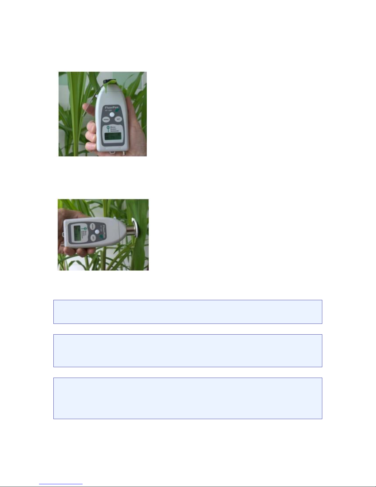
4. Physical Features
* Only in the PAR-FluorPen FP 100-MAX-LM
** Only in the FluorPen FP 100-MAX-W (supplied with a special “open-window” leaf clip).
Leaf clip
Menu key
Set key
Optical window
Textile strap
holder
Light Meter
Sensor *
Optical window
cover **
Page 10

10
5. Accessories
Carrying Case
The FluorPen is supplied with a carrying case which is
padded to protect the instrument during transportation. You
can either carry the FluorPen case over the shoulder or hang
it on your belt.
Protective Rubber Pad
The optical part of the FluorPen is covered with a self-adhesive
rubber pad that protects the optics from dirt or moisture. The
damaged or dirty pad can be easily removed by tearing it off from
the surface. To affix a new one, just remove the sheeting and stick
the pad on cleaned and dried surface. Be sure that you placed the
pad properly and that you did not cover the optical window.
Batteries
The FluorPen operates from four AAA single-use or rechargeable
batteries. They may be easily replaced by unscrewing the cover of
the battery holder on the rear of the instrument. Battery life is
approximately 48 hours when the FluorPen is operated
continuously.
Page 11

11
Detachable leaf-clip
Supplementary detachable leaf-clips for use
with the FluorPen FP 100-MAX-D and PARFluorPen FP 100-MAX-LM-D. Sample holder
is a clip for gentle fixing of a leaf sample and
its short duration dark adaptation. “D”
version of the PAR-FluorPen with detachable
leaf-clips is suitable for experiments where
long term dark adaptation is needed.
Page 12

12
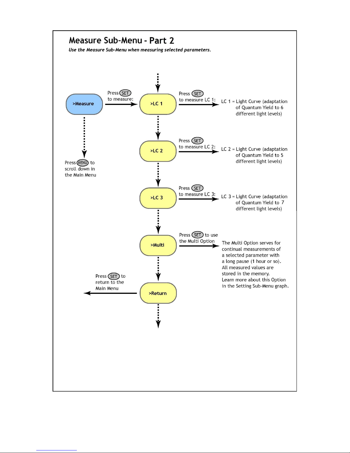
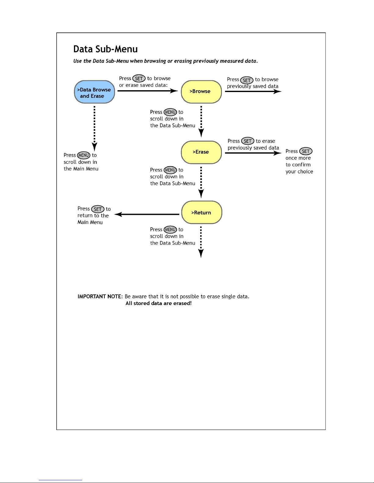
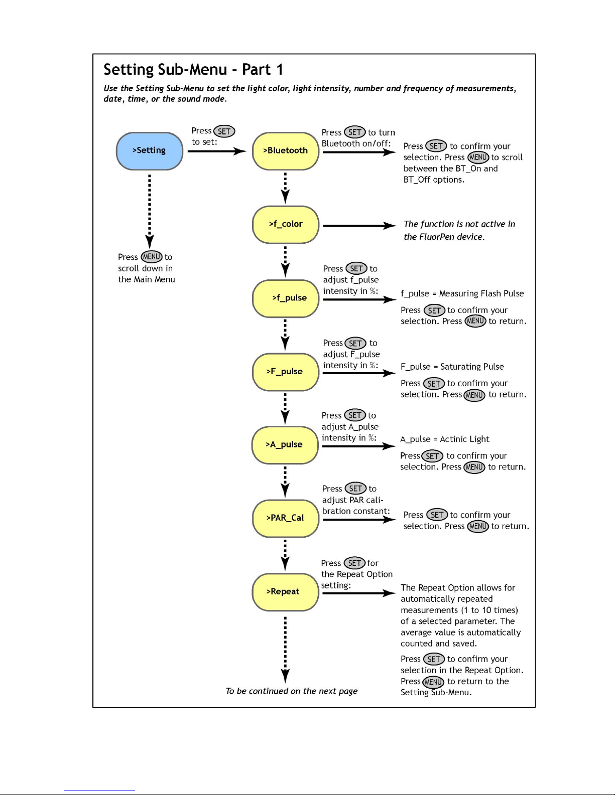
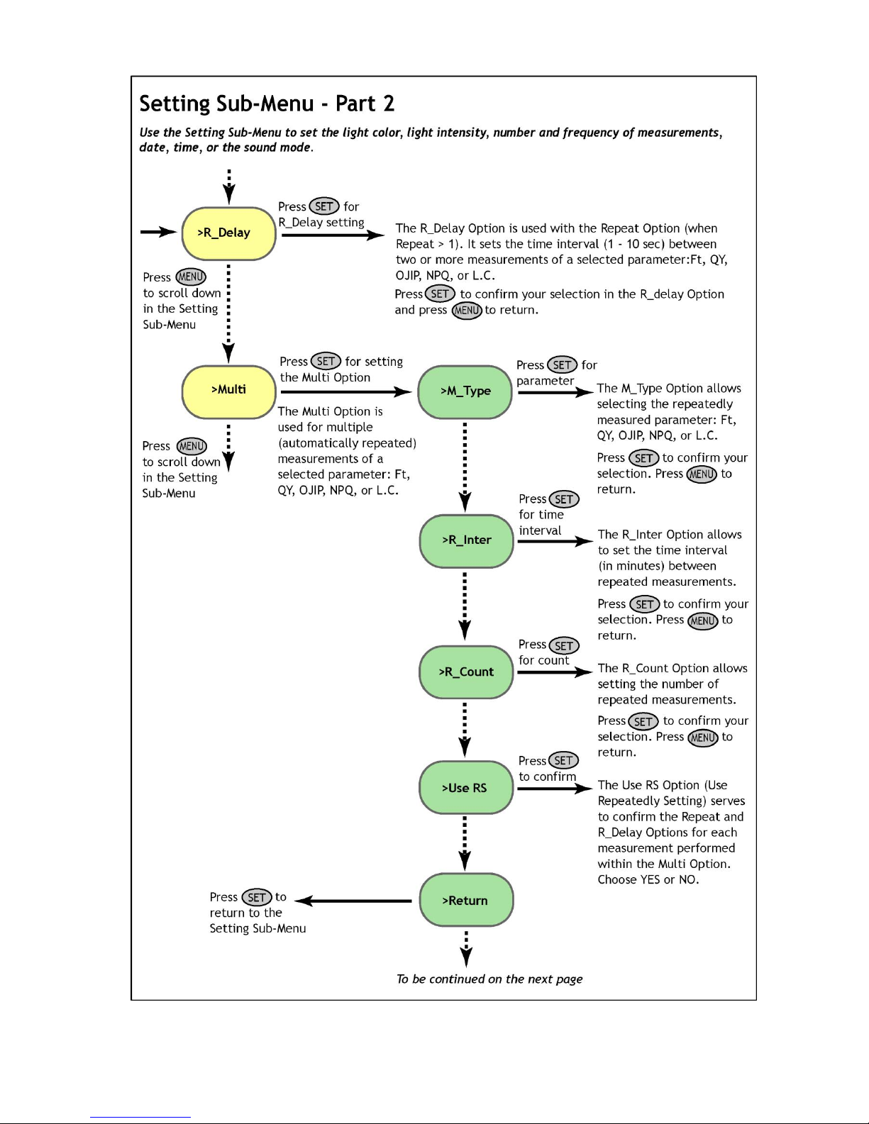
6. Operation Instructions
The next six pages explain the structure of the Main Menu and three Sub-Menus with all their options.
The blue color represents the Main Menu and its Options.
The yellow color represents the first-level Sub-Menus and their Options.
The green color represents the second-level Sub-Menus and their Options.
Full-line arrows are used for the SET key.
Dashed-line arrows are used for the MENU key.
In general:
Use the MENU key to scroll through sequential menu options on the digital display.
Use the SET key to select a menu option based on cursor (>) position.
Page 13

13
Page 14

14
Page 15
15
Page 16
16
Page 17
17
Page 18
18
Page 19

19
Page 20

20
7. Bluetooth Pairing and Connecting
This Chapter applies to users of the FluorPens with an incorporated Bluetooth communication module.
7.A. General Information
What you will need first:
Before you set up the Bluetooth connection between the FluorPen and PC, make sure you have
these components:
1. Bluetooth enabled FluorPen
FluorPen FP 100-MAX and FluorPen FP 100-B include built-in Bluetooth capabilities.
2. Bluetooth enabled PC
The PC with which you connect must have Bluetooth wireless technology, either built-in or through a
Bluetooth card. Make sure that the PC's Bluetooth setting is "discoverable" (meaning that it shows up
when other devices search for nearby Bluetooth connections). Consult the user guide for your PC or
Bluetooth card to learn how to do this.
3. Bluetooth configuration software properly set up on PC
Before you can exchange files with your PC, you will need to set up the Bluetooth software that came with
your PC, or your PC's Bluetooth card. This software varies by manufacturer. Please consult your PC's
Bluetooth documentation for more information.
4. Bluetooth must be switched on visible on both devices
To pair the FluorPen with another Bluetooth device, such as a computer, you will need to ensure that
Bluetooth is switched on visible on both devices.
Page 21
21
7.B. Bluetooth Pairing
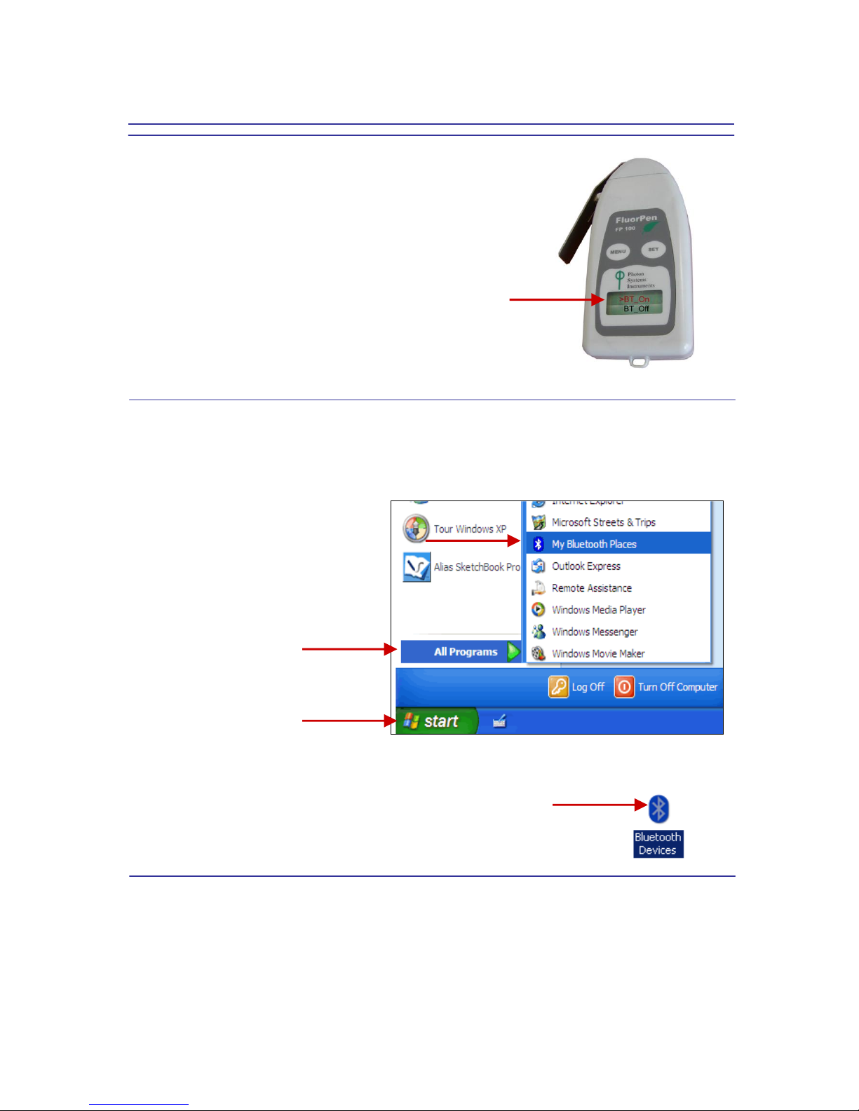
Step 1: Enabling Bluetooth in the FluorPen
Switch on the FluorPen (press and hold the SET key).
Scroll to the “Setting” menu (press the MENU key twice,
then press the SET key once).
Select “BT_On” to enable Bluetooth (press the SET key).
* Keep in mind that the FluorPen turns off automatically after about 3
minutes of no action. Turning off the FluorPen
always turns off Bluetooth.
Step 2: Starting the Bluetooth Application on Your PC
Be aware that this description is a general example; some of the steps may be different on your PC.
Select: Start>All Programs>My Bluetooth
Places.
You may also start your Bluetooth application via the Control Panel:
Select: Start>Settings>Control Panel>Bluetooth Devices.
Page 22

22
Step 3: Opening the Add Bluetooth Device Wizard
Select: “Add” to start the wizard.*
* Before starting to use the wizard, be sure that
the FluorPen is in discoverable mode (see Step
1).
Step 4: Searching for a New Bluetooth Device
Mark the following box: “My device is set up and
ready to be found”.
Select: Next.
Step 5: Selecting the FluorPen
Select: Bluetooth FluorPen icon (FluorPen
FluoroMeter PSI).*
Select: Next.
* Your display may show more Bluetooth Device
icons.
Page 23

23
Step 6: Starting the Pairing Process
Your Bluetooth Pairing Passkey is:
0000
Select: “Let me choose my own passkey.”
Enter: 0000 (four digits).
Select: Next.
Step 7: Completing the FluorPen Pairing
Select: Finish.
Page 24

24
7.C. Bluetooth Connection
Step 1: Installing the FluorPen Software
Install the FluorPen software to your PC. Use the CD that came enclosed with your FluorPen.*
* See Chapter 8 of this Operation Manual for complete information on FluorPen software.
Step 2: Enabling Bluetooth in the FluorPen
Switch on the FluorPen (press and hold the SET key).
Scroll to the “Setting menu” (press the MENU key twice,
then press the SET key once).
Select “BT_On” to enable Bluetooth (press the SET key).*
* Keep in mind that the FluorPen turns off automatically after
about 3 minutes of no action. Turning off the FluorPen
always turns off Bluetooth.
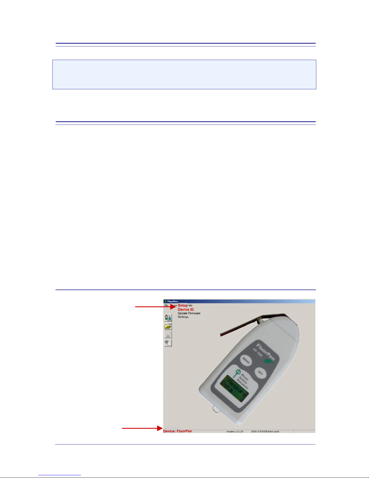
Step 3: Starting Connection
Start the FluorPen software on your PC.
Select: Setup>Device ID (Ctrl+I).
If properly connected, the message “Device:
FluorPen” appears on the bottom part of the
screen.
Page 25

25
Step 4: Registering the FluorPen Software
Select: Help>Register.
Enter your serial (registration) number.*
Select: OK.
* You will find your serial (registration)
number in the file SN.txt on the enclosed CD.
Important Note: How to Reconnect Bluetooth
Disconnection can occur, either when the Bluetooth feature has been turned off in one or both of the
devices, or when the units move outside their operating range.
If the devices have been turned off, simply turn them on and enable Bluetooth in the FluorPen again.
If the FluorPen has been moved outside the Bluetooth operational range, bringing it back into range
within 90 seconds will allow it to reconnect automatically. If more time elapses, simply turn the FluorPen
on and enable Bluetooth again.
Page 26
26
8. USB pairing and connecting
8.A. General Information
What you will need first:
Before you set up the USB connection between the FluorPen and PC, make sure you have these
components:
1. USB enabled FluorPen
FluorPen FP 100-MAX and FluorPen FP 100-U include connector for communication by USB cable.
2. USB cable
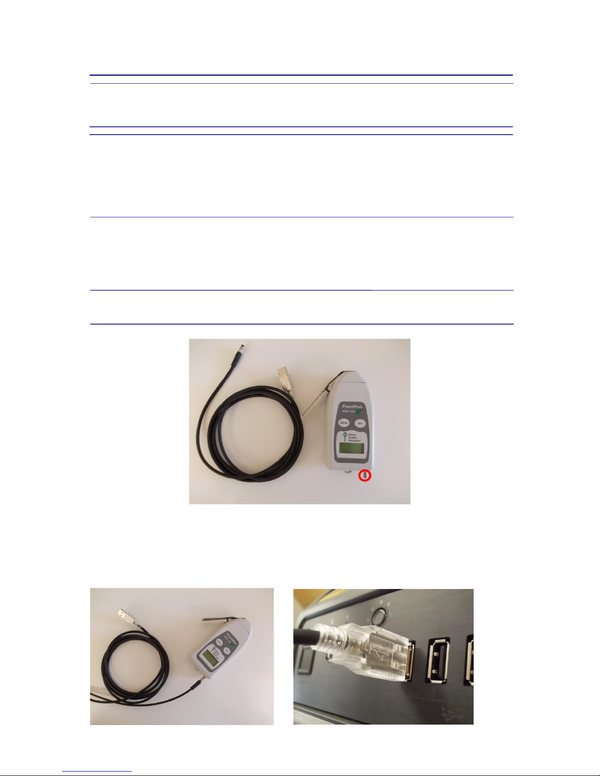
8.B. USB Pairing
Connect the USB cable to a computer and FluorPen as shown below. Then Switch on the FluorPen (press
and hold the SET key). On computer run the program Fluorpen 1.0. Then folow chapter 9. – FluorPen
software.
Page 27
27
9. FluorPen Software
This Chapter applies to users of the FluorPen FP 100-MAX, PAR-FluorPen FP 100-MAX-LM and to users
of the FluorPen FP 100-B and FP 100-U.
9.A. Starting up
Starting up:
1. Switch on the computer.
2. Switch on the FluorPen and enable Bluetooth.*
3. Make sure that your PC and the FluorPen are properly paired.*
4. For FluorPens supplied with the USB communication module, use provided USB cable to connect your
device to a PC. Please note that FluorPens battery is automatically re-charged when connected to the
PC.
5. Start the FluorPen program.
Please note that the device always comes with just one communication module - either USB or Bluetooth.
For USB connection you need to have the USB driver installed in your PC. You find the driver on the
installation disk (USB driver folder). If you check the Device Manager in Windows you should see the USB
serial port in the device tree. In case of missing driver you may download it from the following link:
http://www.psi.cz/ftp/FluorPen/USB_Driver_Setup.exe. When the driver is installed correctly you should
be able to connect to the device in the FluorPen software menu Setup->Device ID.
* Points 2 and 3 apply only to users of the FluorPen FP 100-MAX and FluorPen FP 100-B. See Chapter 7 of this
Operation Manual for complete information on Bluetooth pairing and connecting.
Connecting:
Select: Setup>Device ID (Ctrl+I).
If properly connected, the message
“Device: FluorPen” appears in the bottom
part of the screen.
Page 28

28
9.B. Menu and Icon Explanation
Menu: File
Load Loads previously saved data files.
Save Saves data to hard disc.
Export Exports data in .txt format.
Export to JSON Exports data in JavaScript Object Notation.
Close Closes the current experiment.
Close All Closes all running experiments.
Exit Exits the program.
Menu: Device
Download Downloads data from the FluorPen to your PC.
Erase Memory Erases data from the FluorPen memory.
Online Control Settings sound and time.
Attach GPS File Used for download data from GPS module.
Menu: Setup
Device ID Detects the Bluetooth
connected device.
Update Firmware Used for software updates.*
Settings Used for modification of the
program settings.**
* For more information on software updating, see Chapter 9G of this Operation Manual.
** See more information on the next page.
Menu: Help
About Offers basic information about the program.
Register Used for the FluorPen software registration.*
* See Chapter 7C of this Operation Manual for more information on FluorPen software registration.
Page 29
29
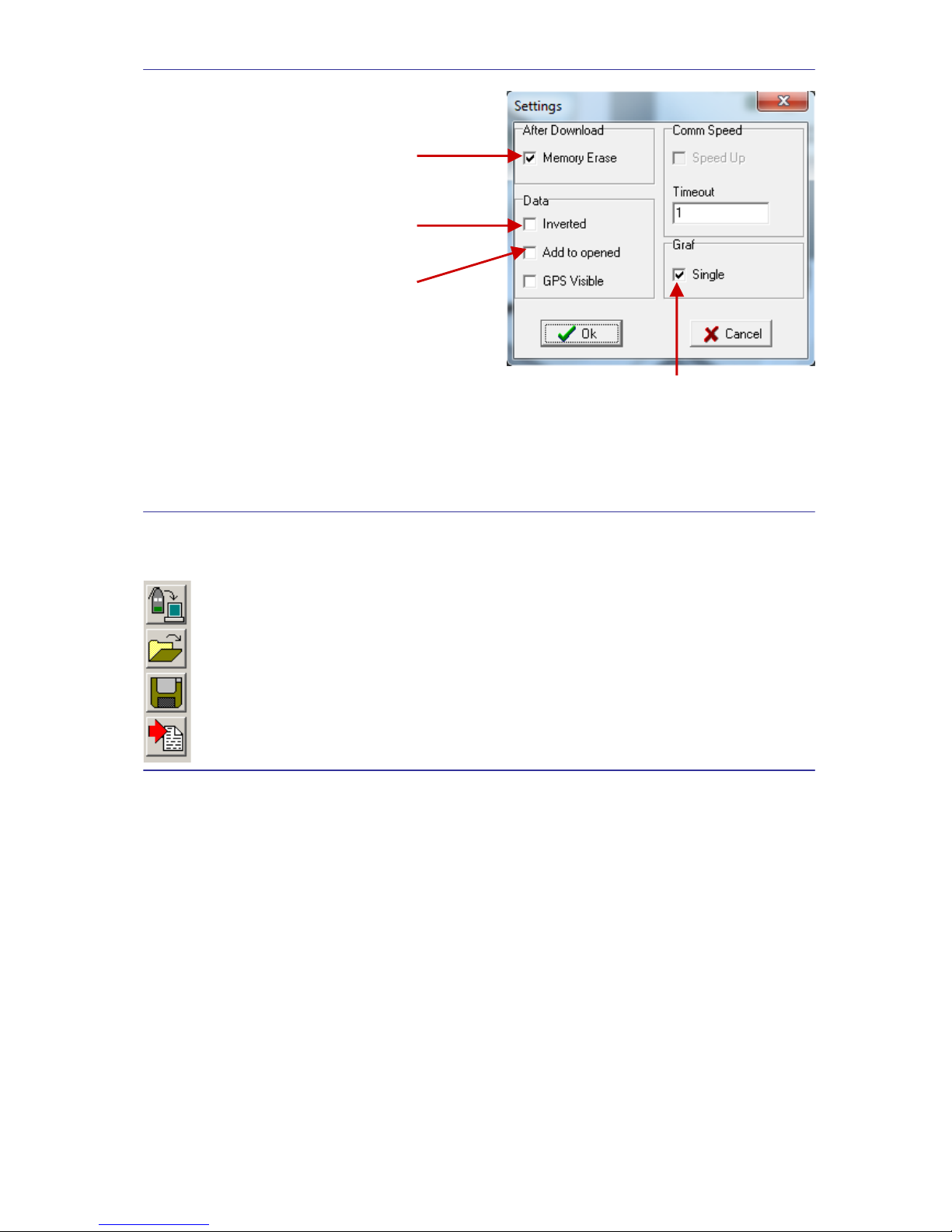
Menu: Settings
After Download - Memory Erase
If the box is checked, the FluorPen memory is erased
after each data download.
Data - Inverted
If the box is checked, the polarity of data is inverted,
e.g., multiplied by -1.*
Data – Add to Opened
If the box is checked, the downloaded data are added to
that of the current opened experiment.
Graf - Single
If the box is checked, all measured data are visualized in one graph, i.e., the value of each new
measurement is added to the currently used graph window.
If the box is not checked, a new graph is opened for every new measurement.
* This feature can be helpful for a certain type of experiment when the measured data are undesirably
interpreted as negative values.
Icon Explanation:
Download Downloads data from the FluorPen to PC.
Load Loads (opens) previously saved data files.
Save Saves data to hard disc.
Export Exports data in .txt format.
Page 30

30
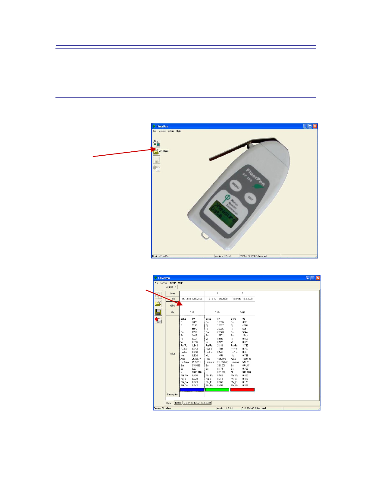
9.C. Example of Data Transfer and Visualization
Step 1: Do a measurement with your FluorPen.
(Here, we did an OJIP measurement.)
Step 2: Click the “Download” icon or select Device>Download.
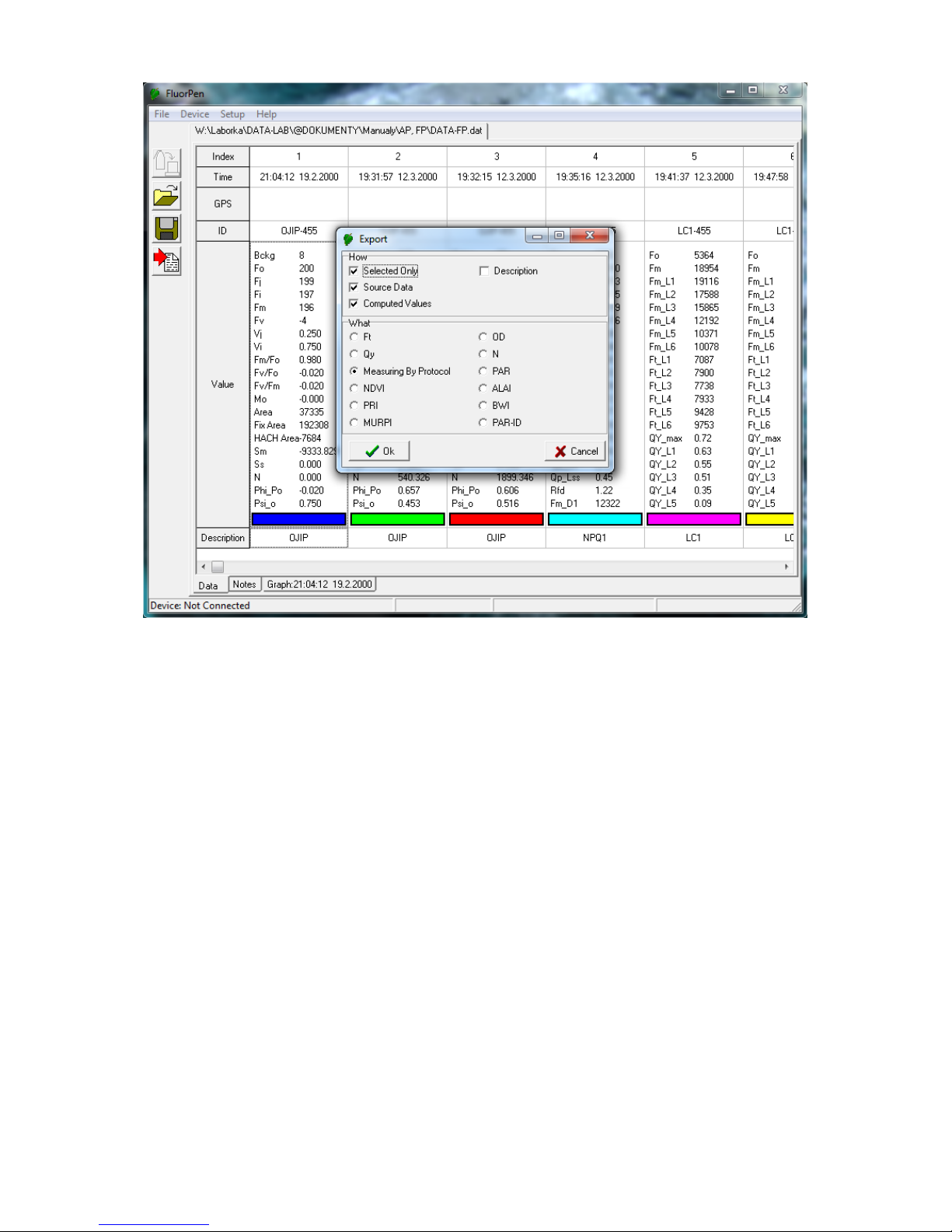
Step 3: The Data table appears.
File name
Time of experiment
Measured parameter
Experiment description
Switch to graphic
visualization of the
experiment
Measured and
calculated values
Save experiment
Space for
written notes
Page 31
31
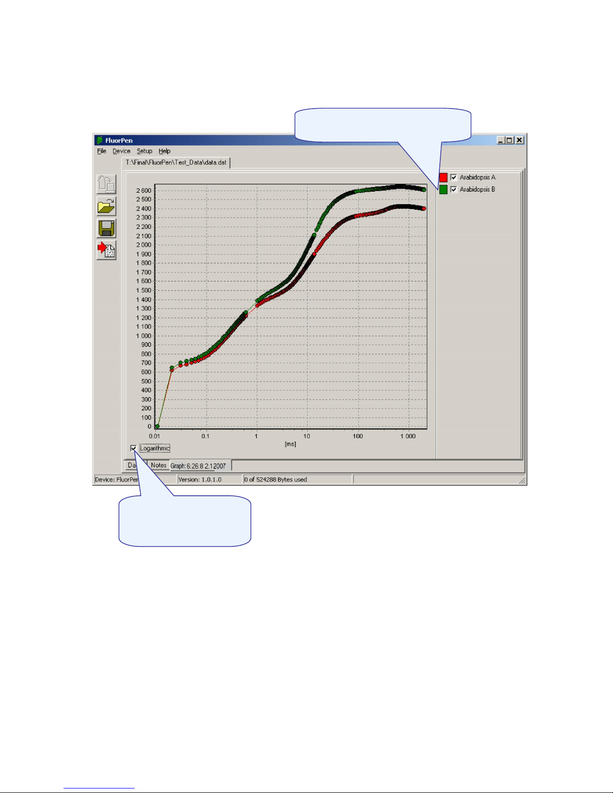
Step 4: To visualize measurement in the graphic mode, click the “Graph” field in the bottom bar.
Step 5: The colored Graph of measured data appears.
Step 6: For export press File>Export or “Export” icon, select what you want to export (Ft, QY, Measuring
by protocol…). Measuring by protocol export all protocols at once (OJIP, NPQ, LC...).
Selected only - exports only one measurement that is selected by mouse, otherwise it will export
everything.
Source data - exports raw data, in case of OJIP: points of the curve
Computed values - export calculated data, in case of OJIP: Fo, Fi, Fj...
Description - exports the data description if any
Selection of data corresponds to
their description
Choose logarithmic or
non-logarithmic graph
form
Page 32
32
Page 33

33
9.D. Explanation of OJIP Parameters
The FluorPen also offers the possibility to capture rapid fluorescence transient – OJIP, which occurs during
exposure of plants to high irradiance. The FluorPen software enables data downloading to a personal
computer and subsequent OJIP analysis. The OJIP protocol includes the following extracted and technical
parameters*:
Formula Abbreviation Formula Explanation
Bckg Background
F0 F0 = F
50µs
, fluorescence intensity at 50 µs
FJ FJ = fluorescence intensity at J-step (at 2 ms)
Fi Fi = fluorescence intensity at i-step (at 60 ms)
FM FM = maximal fluorescence intensity
FV FV = FM - F0 (maximal variable fluorescence)
VJ VJ = ( FJ - F0 ) / ( FM - F0 )
Vi Vi = ( Fi - F0 ) / ( FM - F0 )
FM / F0
FV / F0
Fv / FM
M0 or (dV/dt)0 M0 = TR0 / RC - ET0 / RC = 4 ( F
300
- F0 ) / ( FM - F0 )
Area Area between fluorescence curve and FM (background subtracted)
Fix Area Area below the fluorescence curve between F
40µs
and F
1s
(background
subtracted)
SM SM = Area / ( FM - F0 ) (multiple turn-over)
SS SS = the smallest SM turn-over (single turn-over)
N N = SM . M0 . ( 1 / VJ ) turn-over number Q
A
Phi_P0 Phi_P0 = 1 – ( F
0
/ FM ) (or FV / FM)
Psi_0 Psi_0 = 1 - VJ
Phi_E0 Phi_E0 = ( 1 – ( F0 / F
M
)) . Psi_0
Phi_D0 Phi_D0 = 1 – Phi_P0 – ( F0 / FM )
Phi_Pav Phi_Pav = Phi_P0 ( SM / tFM ) t
FM
= time to reach FM (in ms)
ABS / RC ABS / RC = M0 . ( 1 / VJ ) . (1 / Phi_P0 )
TR0 / RC TR0 / RC = M0 . ( 1 / VJ )
ET0 / RC ET0 / RC = M0 . ( 1 / VJ ) . Psi_0
DI0 / RC DI0 / RC = ( ABS / RC ) – ( TR0 / RC )
* Formulas Derived From:
R.J. Strasser, A. Srivastava and M. Tsimilli-Michael (2000): The fluorescence transient as a tool to characterize
and screen photosynthetic samples. In: Probing Photosynthesis: Mechanism, Regulation and Adaptation (M.
Yunus, U. Pathre and P. Mohanty, eds.), Taylor and Francis, UK, Chapter 25, pp 445-483.
Page 34

34
Example of OJIP protocol
Page 35

35
9.E. Non-Photochemical Quenching (NPQ) Protocol
The NPQ protocol is the most typically used measuring approach to quantify photochemical and nonphotochemical quenching. The measurement should be performed with a dark-adapted sample. Thereby,
it may not be appropriate under field conditions.
The NPQ protocol starts by giving a measuring light to acquire minimal level of fluorescence Fo. A short
saturating flash of light is then applied to reduce the plastoquinone pool and measure maximum
fluorescence in the dark adapted state, Fm. After a short dark relaxation, the sample is exposed to actinic
irradiance for tens to hundreds of seconds to elicit a transient of the Kautsky effect. Moreover, a sequence
of saturating flashes is applied on top of the actinic light to probe the non-photochemical quenching NPQ
and effective quantum yield of photosynthesis QY in light adapted state. After exposure to continuous
illumination, the relaxation of non-photochemical quenching is determined by means of saturating pulses
applied in dark.
Two NPQ protocols, NPQ1 and NPQ2 are predefined. The protocols differ in the duration of the light
exposure and the dark recovery phase, in the number and interval between pulses. See table below.
Phase
Duration
# of pulses
1st pulse
Pulse interval
NPQ1
Light
60s 5 7s
12s
Dark recovery
88s
3
11s
26s
NPQ2
Light
200s
10
10s
20s
Dark recovery
390s
7
20s
60s
Abbreviation
Explanation
Fo
minimum fluorescence in dark-adapted state
Fm
maximum fluorescence in dark-adapted state, measured during the first
saturation flash after dark adaptation
Fp
fluorescence in the peak of fast Kautsky induction
Fm_L, Lss, D, Dss1
maximum fluorescence
QYmax2
maximum quantum yield of PSII in dark-adapted state - Fv/Fm
QY_L, Lss, D, Dss
1,3
effective quantum yield of PSII
NPQ_L, Lss, D, Dss
1,4
non-photochemical chlorophyll fluorescence quenching
Qp_L, Lss, D, Dss
1,5
coefficient of photochemical quenching, an estimate of open PSII reaction
centers
1
L - indicates light adapted parameters; D - refers to dark recovery phase after switching of the actinic
illumination; n - represents a sequential number of light phase; ss - steady state
2
Calculated as (Fm – Fo) / Fm
3
Calculated as (Fm_Ln – Ft_Ln) / Fm_Ln or of corresponding steady state or dark recovery parameters
4
Calculated as (Fm – Fm_Ln) / Fm_Ln or of corresponding ss, Dn or Dss parameters
5
Calculated as (Fm_Ln – Ft_Ln) / (Fm_Ln – Fo_Ln) or of corresponding ss, Dn or Dss parameters
Page 36

36
Page 37

37
Example of NPQ1 protocol
Example of NPQ2 protocol
Page 38

38
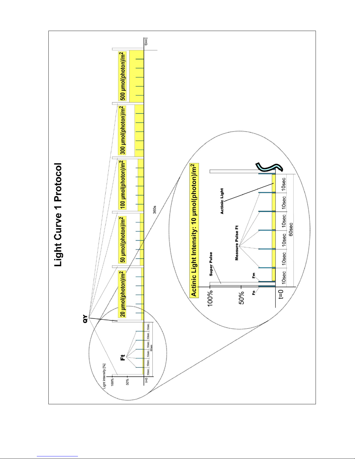
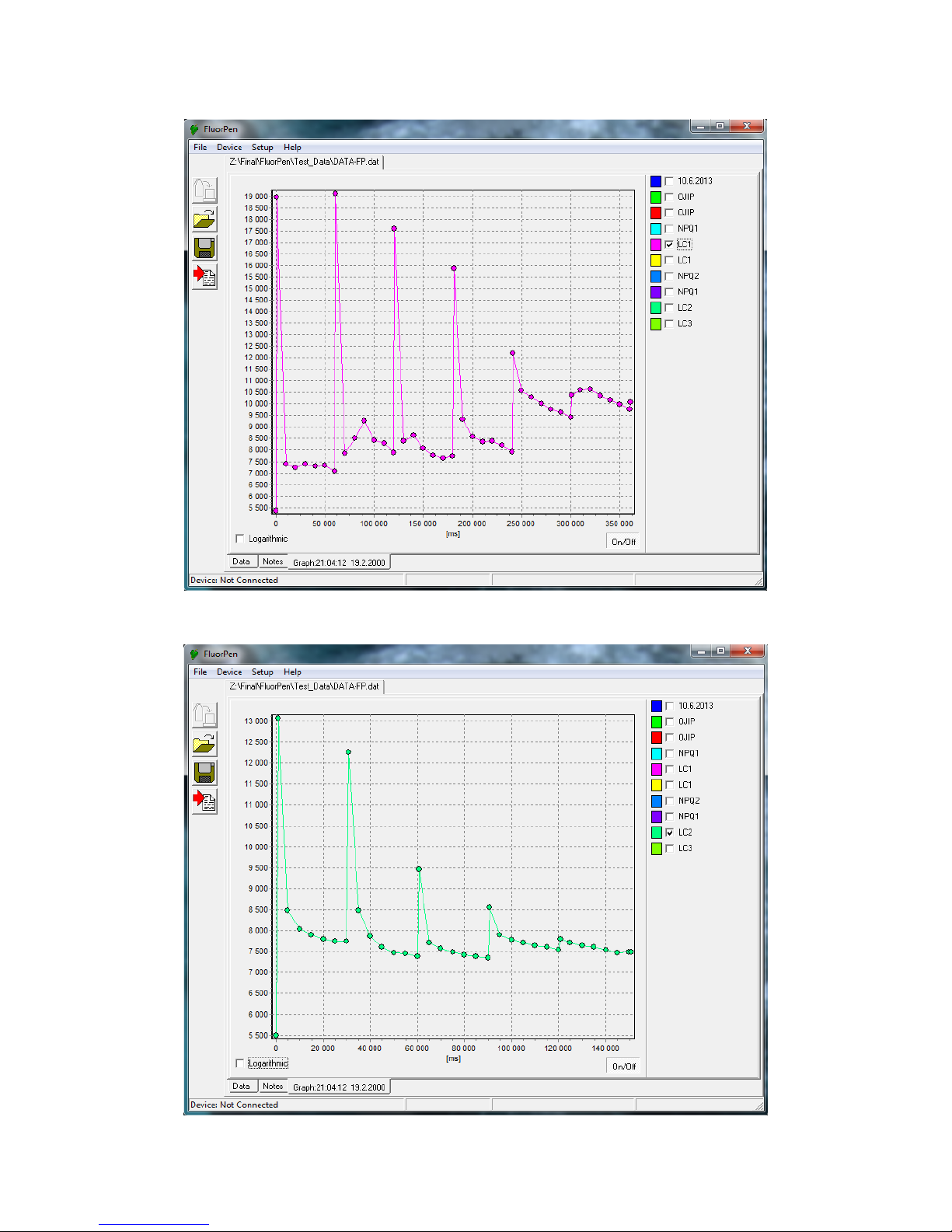
9.F. Light Curve (LC) Protocol
The protocol called Light Curve (LC) was designed to acquire parameters for construction of Light
Response Curve relating the rate of photosynthesis to photon flux density. The method is based on
successive measurements of the sample exposed to a stepwise increase of light intensity. The effective
quantum yields of photosynthesis are determined under various light intensities of continuous
illumination. Measurement is based on pulse modulated fluorometry (PAM).
Several LC protocols are predefined in FP. These differ in number and duration of individual light phases
and light intensities.
# of phases
Phase duration
Light intensities, [mol m-2 s-1]
LC1 6 60s
10; 20; 50; 100; 300; 500
LC2 5 30s
100; 200; 300; 500; 1000
LC3 7 60s
10; 20; 50; 100; 300; 500; 1000
The protocol includes following measured and calculated parameters:
Abbreviation
Explanation
Fo
minimum fluorescence in dark-adapted state
Fm
maximum fluorescence in dark-adapted state
Fm_Ln‡
maximum fluorescence in light adaptation state
Ft_Ln‡
instantaneous fluorescence during light adaptation
QYmax*
maximum quantum yield of PSII in dark-adapted state - Fv/Fm
QY_Ln‡**
instantaneous PSII quantum yield induced in light
‡
n represents a sequential number of light phase
* Calculated as (Fm – Fo) / Fm
** Calculated as (Fm_Lx – Ft_Lx) / Fm_Lx
Page 39
39
Page 40

40
Page 41
41
Example of LC1 protocol
Example of LC2 protocol
Page 42

42
Example of LC3 protocol
Page 43
43
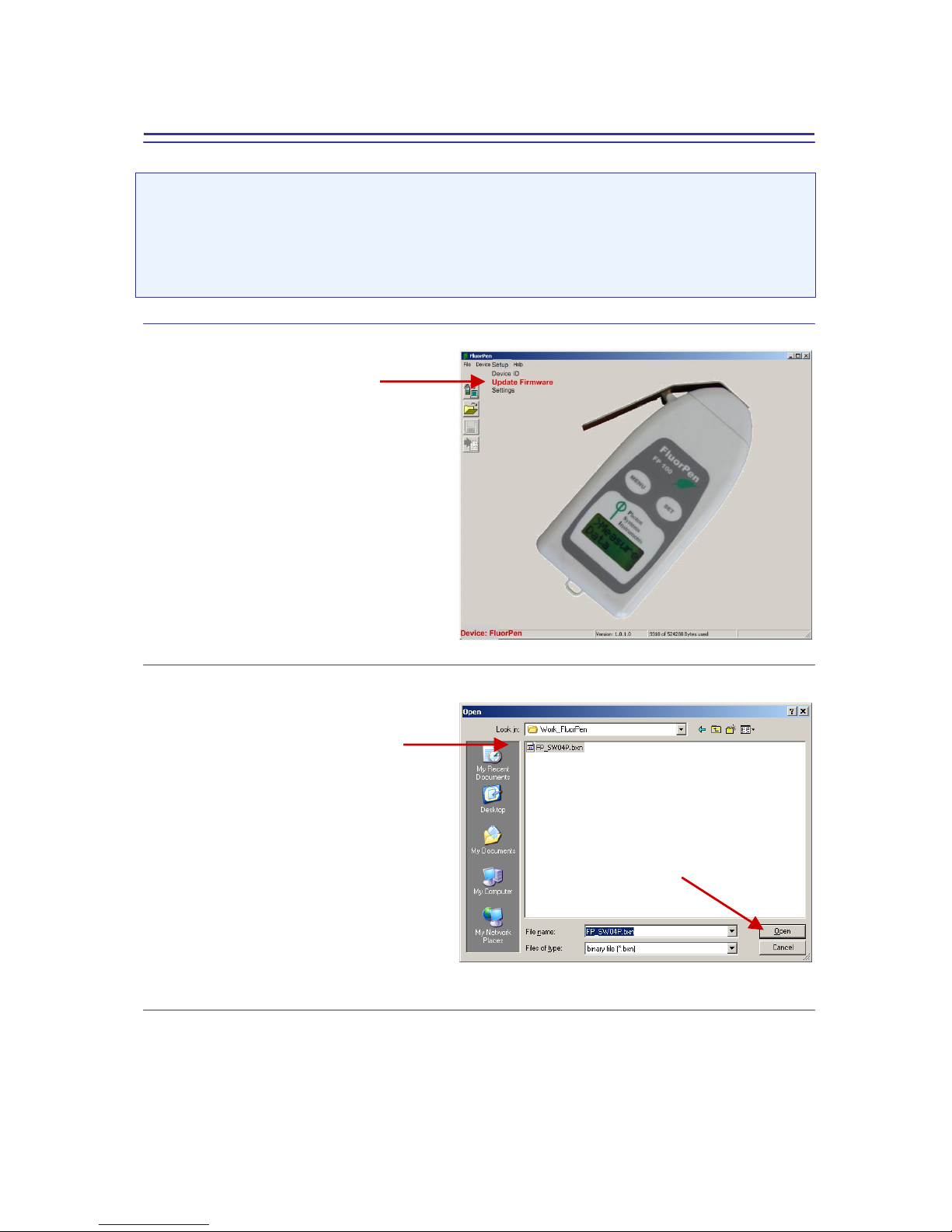
9.G. Software Update
Very important!
The FluorPen memory is erased during the software update!
Before starting any software update, export all your data from the FluorPen memory into your
computer!
Step 1: Starting Update
Select: Setup>Update Firmware
Step 2: Selecting .bxn File
Find: Binary file (with the extension .bxn)
Select: Open
Page 44

44
Step 3: Finishing Upload
Select: “OK” to start uploading of the update.
The bottom bar indicates the upload progress.
Press: “OK” to finish upload.
Page 45

45
10. GPS Module
For all devices in FluorPen Series GMS module might be connected to the device.
IMPORTANT INFORMATION:
For proper GPS reading, the time in your FluorPen and in your computer must be synchronized! Preset time and time zone must correspond to GPS time (time zone) in your location.
10.A. GPS Module Description
Page 46

46
1. Installing AA Batteries
The device operates on two AA batteries. You can use alkaline, NiMH or lithium batteries. Use NiMH of
lithium batteries for best results.
1. Turn the D-ring counter clockwise and pull up to remove the cover.
2. Insert the batteries, observing polarity.
3. Replace the battery cover and turn the D-ring clockwise.
4. Hold
5. Select Setup->System->Battery Type
6. Select Alkaline, Lithium or Rechargeable NiMH
2. Device settings
1. Hold
2. After the device is on, it begins acquiring satellite signals. The device may need a clear view of the
sky to acquire satellite signals.
3. You can check current position and accuracy in Satellite Page
4. For better precision you can enable GPS+GLONASS mode in Setup->System
->Satellite System->GPS+GLONASS and turn WAAS/EGNOS On.
5. Make sure that USB Mode is set to Mass Storage (Setup->System->USB Mode)
For more information please check Garmin eTrex manual.
10.B. First Time Installation of the GPS Module
Step 1: Enabling GPS Module in the FluorPen Software
Select: Setup>Settings
Page 47

47
Select: Settings>GPS visible
Step 2: Accepting GPS Setting
Close and restart the FluorPen program to accept GPS setting.
10.C. GPS / FluorPen Operation
Step 1: Time Synchronization
Synchronize the FluorPen time with the time of your PC. Time must be set correctly witch respect to your
time zone.
Step 2: GPS Positioning
Switch the GPS module on and wait until the GPS position is fixed (GPS green LED indicator flashes 1s ON
and 2s OFF while tracking the position).
Step 3: Operation
Be aware that while performing field experiments, the FluorPen and the GPS module must be kept close to
each other.
Page 48
48
10.D. Data Download
Step 1: Enabling Communication
Switch on the computer, FluorPen, and GPS module and set your computer to FluorPen communication
(enable Bluetooth or connect to serial or USB port).
Step 2: Downloading FluorPen Data
Start: FluorPen program.
Connect: FluorPen device.
Download: Measured data from the
FluorPen to your PC.
Be aware that no GPS coordinates are
visible at this moment.
Page 49

49
Step 3: Connecting GPS Module
Connect the GPS Module to your PC. Communication is set properly if the hardware is recognized by your
PC.
Step 4: Downloading GPS Data
Select:
Device>Attach GPS file
to download data from the GPS
module.
Step 5: Completing the Download
Successfully downloaded GPS
coordinates paired with FluorPen
data.
Page 50

50
11. Statement of Limited Warranty
This Limited Warranty applies only to the FluorPen and its accessories (excluding any batteries).
It is valid one year from the date of shipment.
If at any time within this warranty period the instrument does not function as warranted, return
it and PSI will repair or replace it at no charge. The customer is responsible for shipping and
insurance charges (for the full product value) to PSI. PSI is responsible for shipping and insurance
on return of the instrument to the customer.
No warranty will apply to any instrument that has been (i) modified, altered, or repaired by
persons unauthorized by PSI; (ii) subjected to misuse, negligence, or accident; (iii) connected,
installed, adjusted, or used otherwise than in accordance with the instructions supplied by PSI.
The warranty is return-to-base only, and does not include on-site repair charges such as labor,
travel, or other expenses associated with the repair or installation of replacement parts at the
customer's site.
PSI repairs or replaces faulty instruments as quickly as possible; the maximum time is one month.
PSI will keep spare parts or their adequate substitutes for a period of at least five years.
Returned instruments must be packaged sufficiently so as not to assume any transit damage. If
damage is caused due to insufficient packaging, the instrument will be treated as an out-ofwarranty repair and charged as such.
PSI also offers out-of-warranty repairs. These are usually returned to the customer on a cash-on-
delivery basis.
Wear & Tear Items (such as sealing, tubing, padding, etc.) are excluded from this warranty. The
term Wear & Tear denotes the damage that naturally and inevitably occurs as a result of normal
use or aging even when an item is used competently and with care and proper maintenance.
For customer support, please write to: support@psi.cz
Copyright © Photon Systems Instruments, 2014-08
 Loading...