


EOM
Engineering
Operation &
Maintenance
XSD
Advanced™ Metal
Surge Dampener
Where Innovation Flows
www.wildenpump.com
REPLACES WIL-19011-E-0 6
WI L-19 011 - E - 07

TABLE OF CONTENTS
SECTION 1 CAUTIONS—READ FIRST! ..............................................1
SECTION 2 WILDEN PUMP DESIGNATION SYSTEM .................................2
SECTION 3 HOW IT WORKS—PUMP & AIR DISTRIBUTION SYSTEM ................3
SECTION 4 DIMENSIONAL DRAWINGS .............................................4
SECTION 5 PERFORMANCE
XSD1 ...................................................................6
XSD2 ...................................................................7
XSD3 ...................................................................8
SECTION 6 SUGGESTED INSTALLATION & TROUBLESHOOTING .....................9
SECTION 7 DISASSEMBLY / REASSEMBLY ........................................11
Reassembly Hints & Tips ..................................................14
SECTION 8 EXPLODED VIEW & PARTS LISTING
XSD1 Metal
PTFE/Rubber/SIPD/Ultra-Flex™-Fitted ...................................16
XSD2 Metal
PTFE/Rubber/SIPD/Ultra-Flex™-Fitted ...................................18
XSD2 Metal Advanced
PTFE/Rubber/SIPD/Ultra-Flex™-Fitted ...................................20
XSD3 Metal
PTFE/Rubber/Ultra-Flex™-Fitted ........................................22
SECTION 9 ELASTOMER OPTIONS .................................................24

Section 1
CAUTIONS—READ FIRST!
CAUTION: Do not over-lubricate air supply —
excess lubrication will reduce performance.
CAUTION: Do not exceed 8.6 bar (125 psig) air
supply pressure.
CAUTION: When choosing dampener materials,
be sure to check the temperature limits for
all wetted components. Example: Viton®
has a maximum limit of 177°C (350°F) but
polypropylene has a maximum limit of only 79°C
(175°F) .
CAUTION: Maximum temperature limits are
based upon mechanical stress only. Certain
chemicals will significantly reduce maximum
safe operating temperatures. Consult Chemical
Resistance Guide (E4) for chemical compatibility
and temperature limits.
TEMPERATURE LIMITS:
Polypropylene 0°C to 79°C 32°F to 175°F
PVDF –12°C to 107°C 10°F to 225°F
PFA 7°C to 107°C 20°F to 225°F
Neoprene –18°C to 93°C 0°F to 200°F
Buna-N –12°C to 82°C 10°F to 180°F
EPDM –51°C to 138°C –60°F to 280°F
Viton
®
FKM –40°C to 177°C –40°F to 350°F
Wil-Flex™ –40°C to 107°C –40°F to 225°F
Saniflex™ –29°C to 104°C –20°F to 220°F
Polyurethane –12°C to 66°C 10°F to 150°F
Polytetrafluoroethylene (PTFE)1 4°C to 104°C 40°F to 220°F
EPDM –51°C to 138°C –60°F to 280°F
Nylon –18°C to 93°C 0°F to 200°F
Acetal –29°C to 82°C –20°F to 180°F
SIPD PTFE
SIPD PTFE
with
Neoprene-backed
with
EPDM-backed –10°C to 137°C 14°F to 280°F
4°C to 104°C 40°F to 220°F
Polyethylene 0°C to 70°C 32°F to 158°F
Geolast
1
®
–40°C to 82°C –40°F to 180°F
4°C to 149°C (40°F to 300°F) - 13 mm (1/2”) and 25 mm (1”) models only.
NOTE: Not all materials are available for all
models. Refer to Section 2 for material options
for your pump.
CAUTION: The process fluid and cleaning fluids
must be chemically compatible with all wetted
dampener components. Consult Chemical
Resistance Guide (E4).
CAUTION: Dampener(s) should be thoroughly
flushed before installing into process lines.
FDA- and USDA- approved dampeners should be
cleaned and/ or sanitized before being used.
CAUTION: Always wear safety glasses when
operating dampener. If diaphragm rupture
occurs, process fluid may be forced out air
exhaust.
CAUTION: Before any maintenance or repair
is attempted, the compressed air line to the
dampener and pump should be disconnected
and all air pressure allowed to bleed from the
system. Disconnect all intake, discharge and air
lines. Drain the dampener by allowing any fluid
to flow into a suitable container.
CAUTION: Blow out air line for 10 to 20 seconds
before attaching to dampener to make sure all
pipeline debris is clear. Use an in-line air filter.
A 5μ (micron) air filter is recommended.
CAUTION: Dampeners cannot be used in
submersible applications.
CAUTION: Tighten all hardware prior to
installation.
CAUTION: ATEX products have been assessed
for use in potentially explosive atmospheres in
accordance with the European Directive 94/9/
EC (ATEX 95). Users of ATEX products must be
familiar with ATEX requirements and follow
all safety guidelines. (Refer to Wilden Safety
Supplement WIL-18510-E).
WARNING: Prevent static sparking. If static
sparking occurs, fire or explosion could result.
Dampener, pump, valves and containers must
be grounded to a proper grounding point
when handling flammable fluids and whenever
discharge of static electricity is a hazard.
WIL-19 011- E - 0 7 1 WILDEN PUMP & ENGINEERING, LLC

Section 2
WILDEN DESIGNATION SYSTEM
XSD EQUALIZER
®
LEGEND
XSD X/ XXX X / XX X / XX / XXXX
MATERIAL CODES
REGULATOR BODY
AIR CHAMBER
WETTED PARTS/ OUTER PISTON
INLET SIZE
EQUALIZER® SURGE DAMPENER
DIAPHRAGM
O-RINGS
SPECIALTY CODE
(if applicable)
SPECIALTY CODES
MODEL
XSD = ATEX EQUALIZER®
INLET SIZE
1 = 25 mm (1”)
2 = 51 mm (2”)
3 = 76 mm (3”)
NOTE:
1
XSD1 and XSD2 Only
2
XSD3 Only
SURGE DAMPENER
WETTED PATH/
OUTER PISTON
AA = ALUMINUM/ALUMINUM
SS = STAINLESS STEEL/
STAINLESS STEEL
AIR CHAMBER
A = ALUMINUM
S = STAINLESS STEEL
REGULATOR BODY
A = ALUMINUM
S = STAINLESS STEEL
DIAPHRAGM
BNS = BUNA-N (Red Dot)
FSS = SANIFLEX™ (Cream)
EPS = EPDM (Blue Dot)
NES = NEOPRENE (Green Dot)
PUS = POLYURETHANE (Clear)
TNU = PTFE W/NEOPRENE
TEU = PTFE W/EPDM
VTS = VITON® (Silver or
WFS = WIL-FLEX™ (Orange Dot)
XBS = CONDUCTIVE BUNA-N
ULTRA-FLEX™ DIAPHRAGM
BNU = BUNA-N (Red Dot)
EPU = EPDM (Blue Dot)
NEU = NEOPRENE (Green Dot)
VTU = VITON® (Silver or
O-RINGS
BN = BUNA-N
TF = PTFE (White)
TV = PTFE Encapsulated Viton
White Dot)
(Two Red Dots)
White Dot)
1
2
0014 BSPT
00 40 ASNI Flange Connection (Advanced
NOTE: MOST EL ASTOMERIC MATERIALS USE COLORED DOTS FOR IDEN TIFICATION.
®
Viton
is a registered trademark of DuPont Elastomers.
Hytrel® is a registered trademark of DuPont Elastomers.
Santoprene® is a registered trademark of Exxon Mobil Corporation.
TM
)
WILDEN PUMP & ENGINEERING, LLC 2 WIL-19 011- E - 0 7

AIR
REGULATOR
BODY
AIR
REGULATOR
BODY
AIR
REGULATOR
BODY
LIQUID SIDE LIQUID SIDE LIQUID SIDE
DIAPHRAGM DIAPHRAGM DIAPHRAGM
AIR
SIDE
AIR
SIDE
AIR
SIDE
AIR
REGULATOR
BODY
AIR
REGULATOR
BODY
AIR
SIDE
AIR
SIDE
AIR
REGULATOR
BODY
AIR
SIDE
Section 3
HOW IT WORKS—DAMPENER
All reciprocating pumps generate discharge pressure
fluctuation. The Equalizer
®
minimizes unwanted pressure
fluctuation by providing a supplementary pumping action.
This is accomplished by using a diaphragm as a separation
membrane within the Equalizer
®
to trap a given volume of
liquid on one side and pressurized air on the other.
When the fluid pressure falls in the system, the Equalizer
®
supplies additional pressure to the discharge line between
pump strokes by displacing fluid via diaphragm movement.
This movement provides the supplementary pumping
action needed to reduce pressure variation and pulsation.
PHASE 1 PHASE 3PHASE 2
The Equalizer
®
automatically sets and maintains the
correct air pressure matching the variations in liquid
flow or discharge pressure generated by the pump. A
shaft attached to the Equalizer
®
diaphragm triggers the
addition or removal of the air within the non-wetted side
of the Equalizer
to any pressure and/or flow setting of the pump with no
need for manual adjustment of the unit and/or system.
The Equalizer
®
. The Equalizer® automatically adjusts
®
has proven to be the cost effective choice
for protecting your liquid process system from unwanted
pulsation or pressure fluctuation. Contact your local Wilden
distributor for further information on the Equalizer
other pumping solutions.
®
and
A compressed air line attached to the air regulator body sets
and maintains pressure on the air side of the diaphragm. As
the reciprocating pump begins its stroke, liquid discharge
pressure increases which flexes the Equalizer
®
diaphragm
inward. This action accumulates fluid in the liquid chamber
(see Phase 2) and the air regulator allows compressed air
upon stroke completion, the liquid discharge pressure
decreases and compressed air in the air side forces the
Equalizer
into the discharge line (see Phase 3). This motion provides
the supplementary pumping action needed to minimize
pressure fluctuation.
to enter the air side. When the pump redirects its motion
®
diaphragm to flex outward displacing the fluid
WIL-19 011- E - 0 7 3 WILDEN PUMP & ENGINEERING, LLC

Section 4
XSD1
DIMENSIONAL DRAWINGS
DIMENSIONS — XSD1 METAL
DIMENSION METRIC (mm) STANDARD (inch)
A 295 11.6
B 244 9.6
C 147 5.8
D 295 11.6
E 297 11.7
XSD2
DIMENSIONS — XSD2 METAL
DIMENSION METRIC (mm) STANDARD (inch)
A 315 12.4
B 257 10.1
C 244 9.6
D 455 17.9
E 345 13.6
WILDEN PUMP & ENGINEERING, LLC 4 WIL-19 011- E - 0 7

DIMENSIONAL DRAWINGS
XSD2 Advanced
XSD3
TM
DIMENSIONS -
XSD2 ADVANCED METAL
ITEM METRIC (mm) STANDARD (inch)
A 345 13.6
B 257 10.1
C 279 11.0
D 513 20.2
E 325 12.8
DIN
F 125 DIA 4.9 DIA
G 165 DIA 6.5 DIA
H 18 DIA 0.7 DIA
ANSI
F 122 DIA 4.8 DIA
G 165 DIA 6.5 DIA
H 20 DIA 0.8 DIA
DIMENSIONS — XSD3 METAL
DIMENSION METRIC (mm) STANDARD (inch)
A 399 15.7
B 320 12.6
C 295 11.6
D 556 21.9
E 424 16.7
WIL-19 011- E - 0 7 5 WILDEN PUMP & ENGINEERING, LLC

Section 5
XSD1 TNU
[6.89 bar (100 psig) inlet air / 6.2 bar (90 psig) discharge head]
Time (sec)
0 0.5 1 1.5 2 2.5 3 3.5
Discharge Head
[bar (psig)]
1.4 (20)
2.8 (40)
4.1 (60)
5.5 (80)
6.9 (100)
8.3 (120)
0
0
1.4 (20)
2.8 (40)
4.1 (60)
5.5 (80)
6.9 (100)
8.3 (120)
1 1.5 2 2.5 3 3.5
XSD1 BNU
[6.89 bar (100 psig) inlet air / 6.2 bar (90 psig) discharge head]
Discharge Head
[bar (psig)]
Time (sec)
[4.1 bar (60 psig) inlet air / 3.4 bar (50 psig) discharge head]
5.5 (80)
4.8 (70)
4.1 (60)
3.4 (50)
2.8 (40)
2.1 (30)
1.4 (20)
0.7 (10)
0
Discharge Head [bar (psig)]
1 2
XSD1 PERFORMANCE
XSD1 TNU
Time (sec)
XSD1 BNS
[4.1 bar (60 psig) inlet air / 3.4 bar (50 psig) discharge head]
4.8 (70)
4.1 (60)
3.4 (50)
2.8 (40)
2.1 (30)
1.4 (20)
0.7 (10)
0
Discharge Head [bar (psig)]
1 1.5 2 2.5 3 3.5
Time (sec)
[6.89 bar (100 psig) inlet air / 6.2 bar (90 psig) discharge head]
XSD1 BNS
8.3 (120)
6.9 (100)
5.5 (80)
4.1 (60)
2.8 (40)
1.4 (20)
0
Discharge Head [bar (psig)]
1 1.5 2 2.5 3 3.5
Time (sec)
These charts show discharge head fluctuations for a
diaphragm pump with and without a dampener. By
reviewing the variation in pressure, the level of dampening
can be estimated for an application. For example, the head
pressure generated by a 25 mm (1”) pump operating at
6.89 bar (100 psig) air inlet pressure and 6.2 bar (90 psig)
head pressure varies between 1.7 bar (25 psig) and 7.2
WILDEN PUMP & ENGINEERING, LLC 6 WIL-19 011- E - 0 7
bar (104 psig) resulting in a total pressure fluctuation of
5.5 bar (79 psig) for each stroke. When an XSD1/AAAA/
TNU/TF dampener is installed in the application, the
head pressure varies between 4.8 bar (69 psig) and 6.6
bar (96 psig) resulting in a pressure fluctuation of only
1.9 bar (27 psig). This results in a 67% reduction in head
pressure fluctuation.

XSD2 PERFORMANCE
XSD2 BNS
[4.1 bar (60 psig) inlet air / 3.4 bar (50 psig) discharge head]
Discharge Head
[bar (psig)]
Time (sec)
0
0.7 (10)
1.4 (20)
2.1 (30)
2.8 (40)
3.4 (50)
4.1 (60)
4.8 (70)
0 1 2 3 4 5
0 1 2 3 4 5
XSD2 BNS
[6.89 bar (100 psig) inlet air / 6.2 bar (90 psig) discharge head]
Discharge Head
[bar (psig)]
Time
(sec)
1.4 (20)
0
2.8 (40)
4.1 (60)
5.5 (80)
6.9 (100)
8.3 (120)
1 2 3 4 5
XSD2 TNU
[4.1 bar (60 psig) inlet air / 3.4 bar (50 psig) discharge head]
Discharge Head
[bar (psig)]
Time (sec)
0
1.4 (20)
2.8 (40)
4.1 (60)
5.5 (80)
0
20
40
60
80
100
120
0 1.5 2 2.5 3 3.5 4 4.5 5
XSD2 TNU
[6.89 bar (100 psig) inlet air / 6.2 bar (90 psig) discharge head]
Discharge Head
[bar (psig)]
Time
(sec)
0 1.5 2 2.5 3 3.5 4 4.5 5
XSD2 BNU
[6.89 bar (100 psig) inlet air / 6.2 bar (90 psig) discharge head]
Discharge Head
[bar (psig)]
Time
(sec)
0
1.4 (20)
2.8 (40)
4.1 (60)
5.5 (80)
6.9 (100)
8.3 (120)
1 2 3 4 5
XSD2 BNU
[4.1 bar (60 psig) inlet air / 3.4 bar (50 psig) discharge head]
Discharge Head
[bar (psig)]
Time
(sec)
0
0.7 (10)
1.4 (20)
2.1 (30)
2.8 (40)
3.4 (50)
4.1 (60)
These charts show discharge head fluctuations for a
diaphragm pump with and without a dampener. By
reviewing the variation in pressure, the level of dampening
can be estimated for an application. For example
in reference to XSD2 BNS 100/90, the head pressure
generated by a 51 mm (2") pump operating at 6.89 bar (100
psig) air inlet pressure and 6.2 bar (90 psig) head pressure
WIL-19 011- E - 0 7 7 WILDEN PUMP & ENGINEERING, LLC
varies between 0.4 bar (6 psig) and 7 bar (102 psig)
resulting in a total pressure fluctuation of 6.6 bar (96 psig)
for each stroke. When an XSD2/AAAA/BNS/BN dampener
is installed in the application, the head pressure varies
between 4.7 bar (68 psig) and 6.8 bar (99 psig) resulting in
a pressure fluctuation of only 2.1 bar (31 psig). This results
in a 68% reduction in head pressure fluctuation.

XSD3 PERFORMANCE
1 2 3 4 5 6 7
XSD3 TNU
[6.89 bar (100 psig) inlet air / 6.2 bar (90 psig) discharge head]
Discharge Head
[bar (psig)]
Time
(sec)
0
1.4 (20)
2.8 (40)
4.1 (60)
5.5 (80)
6.9 (100)
8.3 (120)
1 2 3 4 5 6 7
XSD3 TNU
[4.1 bar (60 psig) inlet air / 3.4 bar (50 psig) discharge head]
Discharge Head
[bar (psig)]
Time (sec)
0.7 (10)
0
1.4 (20)
2.1 (30)
2.8 (40)
3.4 (50)
4.1 (60)
1 2 3 4 5 6 7
XSD3 BNU
[6.89 bar (100 psig) inlet air / 6.2 bar (90 psig) discharge head]
Discharge Head
[bar (psig)]
Time
(sec)
0
1.4 (20)
2.8 (40)
4.1 (60)
5.5 (80)
6.9 (100)
8.3 (120)
1 2 3 4 5 6 7
XSD3 BNU
[4.1 bar (60 psig) inlet air / 3.4 bar (50 psig) discharge head]
Discharge Head
[bar (psig)]
Time (sec)
0.7 (10)
0
1.4 (20)
2.1 (30)
2.8 (40)
3.4 (50)
4.1 (60)
1 2 3 4 5 6 7
XSD3 BNS
[6.89 bar (100 psig) inlet air / 6.2 bar (90 psig) discharge head]
Discharge Head
[bar (psig)]
Time
(sec)
0
1.4 (20)
2.8 (40)
4.1 (60)
5.5 (80)
6.9 (100)
8.3 (120)
1 2 3 4 5 6 7
XSD3 BNS
[4.1 bar (60 psig) inlet air / 3.4 bar (50 psig) discharge head]
Discharge Head
[bar (psig)]
Time (sec)
0.7 (10)
0
1.4 (20)
2.1 (30)
2.8 (40)
3.4 (50)
4.1 (60)
These charts show discharge head fluctuations for a
diaphragm pump with and without a dampener. By
reviewing the variation in pressure, the level of dampening
can be estimated for an application. For example
(XSD3 BNU 100/90), the head pressure generated by
a 76 mm (3”) pump operating at 6.89 bar (100 psig) air
inlet pressure and 6.2 bar (90 psig) head pressure varies
WILDEN PUMP & ENGINEERING, LLC 8 WIL-19 011- E - 0 7
between 2.1 bar (30 psig) and 6.5 bar (94 psig) resulting
in a total pressure fluctuation of 4.4 bar (64 psig) for
each stroke. When an XSD3/AAAA/BNU/BN dampener
is installed in the application, the head pressure varies
between 4.8 bar (69 psig) and 6.3 bar (91 psig) resulting of
a pressure fluctuation of only 1.5 bar (22 psig). This results
in a 66% reduction in head pressure fluctuation.

Section 6
SUGGESTED INSTALLATION
The model XSD1 has a 25 mm (1") inlet/discharge. The model
XSD2 has a 51 mm (2") inlet/discharge and the XSD3 has a
76 mm (3") inlet/discharge. The Equalizer® can be installed
in either horizontal or vertical orientations. A variety of
materials are available to satisfy temperature, chemical
compatibility, abrasion and flex concerns.
The Equalizer
®
installed on the discharge side of the pump
minimizes pulsation and protects in-line equipment. It can
also be connected on the suction side to prevent water
hammer associated with a positive inlet condition.
Install the Equalizer
®
as shown below. The use of flexible
connections and a Filter, Regulator, Lubricator (FRL) will
extend parts life. Shut-off valves on the suction side of
FLEXIBLE CONNECTION
PRESSURE GAUGE
SHUT-OFF VALVE
SHUT-OFF VALVE
SUCTION LINE
pump and the discharge side of Equalizer
®
will enable
maintenance personnel to safely service the equipment.
To maximize effectiveness, install the Equalizer® as close
as possible to the discharge of the pump.
It is important to support the pipe immediately
downstream from the Equalizer
®
. Use a tee connector
on the pump air supply line and connect the line to the
Equalizer® regulator body. This tee connector should be
installed after the FRL. The Equalizer® consumes very
little air, therefore, a 1/4” hose is more than adequate to
supply enough air volume. When the air supply to the
pump is shut down, the air to the Equalizer® will be shut
off as well.
PRESSURE GAUGE
AIR INLET
AIR SUPPLY
AIR SHUT-OFF VALVE
COMBINATION FILTER AND REGULATOR
NEEDLE VALVE
SHUT-OFF VALVE
SHUT-OFF VALVE
DISCHARGE LINE
FLEXIBLE CONNECTION
NOTE: In the event of a power failure, the shut-off
valve should be closed if the restarting of the pump is
not desirable once power is regained.
the shut-off valve (user supplied) installed in the air
supply line. A properly functioning valve will stop the
air supply to the pump, therefore stopping output. This
shut-of f valve should be located far enough away from
AIR-OPERATED PUMPS: To stop the pump from
operating in an emergency situation, simply close
WIL-19 011- E - 0 7 9 WILDEN PUMP & ENGINEERING, LLC
the pumping equipment such that it can be reached
safely in an emergency situation.

TROUBLESHOOTING
1) When there is a significant drop in the fluid discharge
pressure, there will be a noticeable release of air
through the small bleed hole in the air regulator
body. This is how the Equalizer
®
automatically adjusts
itself for optimal suppression. This is a good way
of verifying proper operation of the unit. If there is
a continuous discharge of air out of this hole during
®
steady fluid discharge pressure, the Equalizer
is not
functioning properly and should be inspected. The air
regulator body houses three (3) Glyd rings.
2) Fluid leakage around the clamp band area is normally
stopped by tightening the clamp band bolts. If
leakage continues, unit should be disassembled and
inspected.
3) Air leakage between the adapter plate and air chamber
requires tightening of four air chamber bolts on the
inside of the air chamber.
WILDEN PUMP & ENGINEERING, LLC 10 WIL-19 011- E - 0 7

Section 7
DAMPENER DISASSEMBLY
Tools Required:
• Deep well sockets and
ratchet (7/16”, 1/2” and
3/4”)
®
• Hex (Allen
(3/16” and 1/4”)
• Large adjustable wrench
or channel lock pliers
) wrenches
Tools Recommended:
• Large pipe wrench
• Vise equipped w/soft
jaws (such as aluminum,
plastic, plywood or other
suitable material)
CAUTION: Before any maintenance or repair is attempted, the compressed
air line to the Equalizer
pressure allowed to bleed from the system. Disconnect all intake, discharge,
and air lines. Be aware of any hazardous ef fects of contact with your process
fluid. PLEASE READ ALL DIRECTIONS BEFORE STARTING DISASSEMBLY.
NOTE: The model photographed for these instructions is a XSD1. Other
Equalizer
different components and fastener sizes.
®
models should be similar in design but may contain slightly
®
and the pump should be disconnected and all air
Step 1
Disassembly of the surge ends/
small clamp band is needed only
in the event of leakage. Leakage is
usually stopped by tightening the
small band bolts using a 7/16” deep
well socket.
WIL-19 011- E - 0 7 11 WILDEN PUMP & ENGINEERING, LLC
Step 2
If leakage persists, remove surge
ends and replace O-rings.
Step 3
Remove large clamp band using a
1/2” deep well socket.

DAMPENER DISASSEMBLY
Step 4
Set liquid chamber aside.
Step 5
Remove reducer bushing at top of
regulator.
Step 6
Loosen shaft assembly by using
adjustable wrench on outer piston
and 3/4” socket on shaft bolt inside
air regulator body. Turn counter
clockwise. One of two scenarios will
occur: outer piston will loosen from
shaft, or the shaft bolt will loosen
from shaft.
Step 7
In either case, this will allow the
removal of the inner and outer
pistons, diaphragm, shaft stop,
shaft, shaft stop washer and bolt.
WILDEN PUMP & ENGINEERING, LLC 12 WIL-19 011- E - 0 7
Step 8
Inspect shaft for nicks or abrasion.
Small nicks can usually be dressed
out. If shaft is chemically attacked or
nicks are hindering operation, shaft
should be replaced.
Step 9
Disassembly of the air chamber
from the regulator adaptor plate
is needed only in the event of air
leakage.
DAMPENER DISASSEMBLY
Step 10
In the event of an air leak, remove
the air chamber and replace the
gasket.
Step 11
Disassembly of the regulator body
from the regulator adaptor plate
is needed only in the event of air
leakage.
1
3
5
Step 12
In the event of an air leak, remove
the regulator adaptor plate and
replace the O-ring.
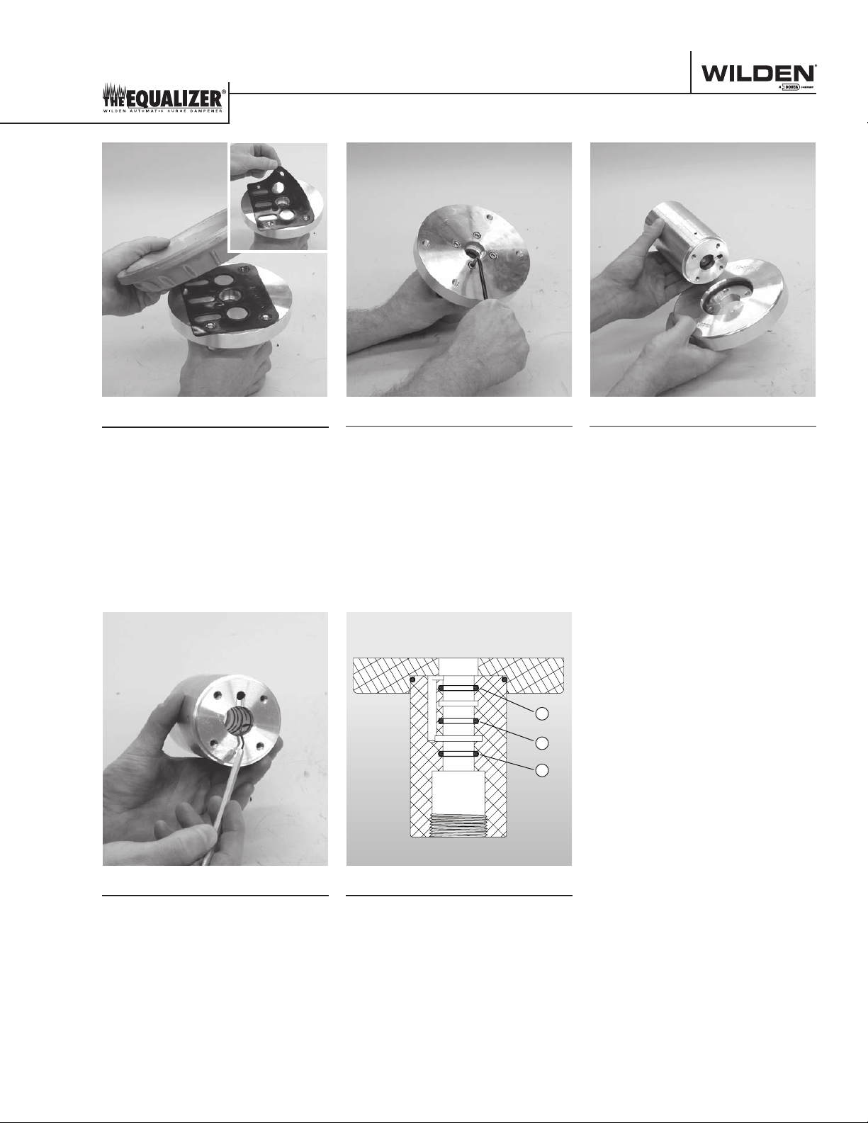
Step 13
Using an O-ring pick, remove the
Glyd rings from air regulator body.
Step 14
The air regulator body has five
(5) grooves cut into the inside
diameter. There are three Glyd rings
installed in the 1, 3 and 5 positions.
It is important that these Glyd rings
be installed in the correct grooves
®
so that the Equalizer
functions
properly. Please refer to the drawing
for the correct location of the Glyd
rings.
WIL-19 011- E - 0 7 13 WILDEN PUMP & ENGINEERING, LLC

REASSEMBLY HINTS & TIPS
AS SE MB LY:
Upon performing applicable maintenance to the
air distribution system, the Equalizer® can now
be reassembled. Please refer to the disassembly
instructions for photos and parts placement. To
reassemble the Equalizer®, follow the disassembly
instructions in reverse order. The air regulator body
needs to be assembled first, then the diaphragm and
finally the wetted path. Please find the applicable
torque specifications on this page. The following tips
will assist in the assembly process.
• Lubricate air regulator body , Glyd rings and shaft
bore center with NLGI grade 2 white EP bearing
grease or equivalent.
• Clean the inside of the air regulator body bore to
ensure no damage is done to new shaft seals.
• Stainless bolts should be lubed to reduce the
possibility of seizing during tightening.
MAXIMUM TORQUE SPECIFICATIONS
Model Description of Part Torque
Air chamber/adapter plate 24.4 N·m (18 ft-lb)
Air regulator body/adapter plate 7.9 N·m (70 in-lb)
XSD1
Outer piston/shaft bolt assembly
(all diaphragms)
Air chamber/adapter plate 24.4 N·m (18 ft-lb)
Air chamber/adapter plate 7.9 N·m (70 in-lb)
Outer piston/shaft bolt assembly
XSD2
(rubber & PTFE)
Outer piston/shaft bolt assembly
(Ultra-Flex™ & SIPD)
Air chamber/adapter plate 44.7 N·m (33 ft-lb)
Air regulator body/adapter plate 7.9 N·m (70 in-lb)
XSD3
Outer piston/shaft bolt assembly
(all diaphragms)
Figure A
SHA FT SE AL
54.2 N·m (40 ft-lb)
109 N·m (80 ft-lb)
74.6 N·m (55 ft-lb)
136 N·m (100 ft-lb)
SHAFT SEAL INSTALLATION:
PRE-INSTALLATION
• Once all of the old seals have been removed, the
inside of the air regulator body should be cleaned
to ensure no debris is left that may cause premature
damage to the new seals.
INSTALLATION
The following tools can be used to aid in the installation
of the new seals:
Needle Nose Pliers
Phillips Screwdriver
Electrical Tape
• Wrap electrical tape around each leg of the needle nose
pliers (heat shrink tubing may also be used). This is done
to prevent damaging the inside surface of the new seal.
• With a new seal in hand, place the two legs of the needle
nose pliers inside the seal ring. (See Figure A.)
• Open the pliers as wide as the seal diameter will allow,
then with two fingers pull down on the top portion of
the seal to form kidney bean shape. (See Figure B.)
• Lightly clamp the pliers together to hold the seal into
the kidney shape. Be sure to pull the seal into as tight
of a kidney shape as possible, this will allow the seal to
travel down the bushing bore easier.
• With the seal clamped in the pliers, insert the seal into
the bushing bore and position the bottom of the seal
into the correct groove. Once the bottom of the seal is
seated in the groove, release the clamp pressure on the
pliers. This will allow the seal to partially snap back to its
original shape.
• After the pliers are removed, you will notice a slight
bump in the seal shape. Before the seal can be properly
resized, the bump in the seal should be removed as
much as possible. This can be done with either the
Phillips screwdriver or your finger. With either the side
of the screwdriver or your finger, apply light pressure
to the peak of the bump. This pressure will cause the
bump to be almost completely eliminated.
• Lubricate the edge of the shaft with NLGI grade 2
white EP bearing
• Slowly insert the center shaft with a rotating motion.
This will complete the resizing of the seal.
• Perform these steps for the remaining seal.
Figure B
grease.
NEEDLE NOSE
PLIERS
TAPE
WILDEN PUMP & ENGINEERING, LLC 14 WIL-19 011- E - 0 7
SHA FT SE AL
TAPE

NOTES

Section 8
EXPLODED VIEW & PARTS LISTING
XSD1 ORIGINAL
7
TM
28
27
26
1
3
4
5
6
8
METAL
2
EXPLODED VIEW
27
26
19
20
21
22
24
23
25
PTFE FITTED
RUBBER FITTED
19
20
21
22
23
25
10
11
17
13
12
9
14
16
15
18
27
26
19
20
21
22
23
27
29
26
19
21
22
23
25
SIPD FITTED
ULTRA-FLEX FITTED
WILDEN PUMP & ENGINEERING, LLC 16 WIL-19 011- E- 07

EXPLODED VIEW & PARTS LISTING
XSD1 ORIGINAL
No. Part Description Qty.
1 Body, Regulator
2 Ring II, Glyd 3 08-3210-55-225 08-3210-55-225
3 O-Ring -230 (Ø2.484 x Ø.139) 1 76-1285-52 76-1285-52
4 Plate, Regulator Adapter 1 76-8510-01 76-8510-03
5 Screw, 1/4-20 x .75 Soc Hd Cap 4 76-6250-03 76-6250-03
6 Gasket, Center Block 1 04-3529-52 04-3529-52
7 Chamber, Air 1 04-3660-01 04-3660-03
8 Screw, 3/8-16 x 1.00 Soc Flt Csk Hd Cap 4 71-6250-08 71-6250-08
9 Chamber, Liquid 1 04-5000-01 04-5000-03
10 Clamp Band, Half 2 04-7330-08 04-7330-03
11 Bolt, 5/16-18 x 2.50 Rnd Hd Sq Neck 2 04-6070-03 04-6070-03
12 Washer, Plain 2 01-6732-03 01-6732-03
13 Nut, 5/16-18 Hex 2 04-6420-08 08-6400-03
14 O-Ring -229 (Ø2.359 x Ø.139) 2 * *
15 End, 1” NPT Surge 2 70-8600-01 70-8600-03
End, 1” BSPT Surge 2 70-8600-01-14 70-8600-03-14
16 Clamp Band Small 4 04-7100-08 04-7100-03
17 Bolt, 1/4-20 x 2.00 Rnd Hd Sq Neck 4 04-6050-08 01-6070-03
18 Nut, 1/4-20 Hex 4 04-6400-08 04-6400-03
19 Shaft, Straight 1 76-3800-03 76-3800-03
Shaft, Ultra-Flex™ 1 04-3830-03-07 04-3830-03-07
20 Stud, 1/2-20 x 1.50 Threaded 1 04-6150-08 04-6150-08
21 Stop, Shaft 1 76-8800-17 76-8800-17
22 Piston, Rubber & TPE Inner 1 04-3700-01-700 04-3700-01-700
Piston, Ultra-Flex™ Inner 1 04-3760-01-700 04-3760-01-700
Piston, PTFE Inner 1 04-3755-01 04-3755-01
Piston, SIPD Inner 1 04-3700-08 04-3700-08
23 Diaphragm, Primary 1 * *
Diaphragm, Ultra-Flex™ 1 * *
Diaphragm, PTFE 1 * *
Diaphragm, SIPD 1 * *
24 Diaphragm, Back-Up 1 * *
25 Piston, Rubber & TPE Outer 1 04-4552-01 04-4550-03
Piston, Ultra-Flex™ Outer 1 04-4560-01 02-4550-03
Piston, PTFE Outer 1 04-4600-01 04-4600-03
26 Washer, Stop 1 70-6790-08 70-6790-08
27 Screw, Hex Cap, 1/2-20 x 1.00 1 04-6090-08 04-6090-08
Screw, Hex Hd Cap, 3/8-16 x .88, Ultra-Flex™ 1 08-6140-08 08-6140-08
28 Reducer Bushing 1 70-6950-08 71-6950-03
29 Washer, (.406 ID x .812 OD x .065 THK) Ultra-Flex™ 1 15-6740-08-50 15-6740-08-50
1
Air Regulator Body includes qty. 3 Glyd Rings.
*Elastomer options listed on page 24.
All Bold face items are primary wear items.
TM
METAL
XSD1/AAAA/
P/N
1
1 76-8515-01 76-8515-03
XSD1/SSSS/
PARTS LISTING
P/N
WIL-19 011- E - 0 7 17 WILDEN PUMP & ENGINEERING, LLC

EXPLODED VIEW & PARTS LISTING
XSD2 ORIGINAL
7
TM
METAL
27
26
25
1
2
3
4
5
6
8
18
EXPLODED VIEW
26
25
18
20
19
21
23
22
24
26
25
18
20
19
21
22
24
PTFE FITTED
RUBBER FITTED
20
19
21
22
24
10
11
16
12
9
13
14
15
17
26
25
18
20
19
21
22
26
25
18
20
19
21
22
24
SIPD FITTED
ULTRA-FLEX FITTED
WILDEN PUMP & ENGINEERING, LLC 18 W IL-19 0 11- E-07

EXPLODED VIEW & PARTS LISTING
XSD2 ORIGINAL
No. Part Description Qty.
1 Body, Regulator
2 Ring II, Glyd 3 08-3210-55-225 08-3210-55-225
3 O-Ring -230 (Ø2.484 x Ø.139) 1 76-1285-52 76-1285-52
4 Plate, Regulator Adapter 1 76-8510-01 76-8510-03
5 Screw, 1/4-20 x .75 Soc Hd Cap 4 76-6250-03 76-6250-03
6 Gasket, Center Block 1 04-3529-52 04-3529-52
7 Chamber, Air 1 08-3660-01 08-3660-03
8 Screw, 3/8-16 x 1.00 Soc Flt Csk Hd Cap 4 71-6250-08 71-6250-08
9 Chamber, Liquid 1 08-5000-01 08-5000-03
10 Clamp Band, Half 2 08-7300-08 08-7300-03
11 Screw, 3/8-16 x 3.00 Hex Cap 2 08-6120-08 08-6120-03
12 Nut, 3/8-16 Heavy Hex 2 08-6450-08 08-6450-03
13 O-Ring -235 (Ø3.109 x Ø.139) 2 * 71-1280-55
14 End, 2” NPT Surge 2 71-8601-01 71-8601-03
End, 2” BSPT Surge 2 71-8601-01-14 71-8601-03-14
15 Band, Small Clamp 4 08-7100-08 08-7100-08
16 Bolt, 5/16-18 x 1.50 Rnd Hd Sq Neck 4 08-6050-08 08-6050-08
17 Nut, 5/16-18 Hex 4 04-6420-08 04-6420-03
18 Shaft, Straight 1 77-3800-03 77-3800-03
19 Stop, Shaft 1 71-8800-17 71-8800-17
20 Adapter, Shaft Stud Rubber Fitted 1 71-6153-08 71-6153-08
Stud, 1/2- 20 x 1.88 Threaded Ultra-Flex 1 08-6150-08 08-6150-08
Stud, 1/2- 20 x 2.13 Threaded PTFE 08-6152-08 08-6152-08
21 Piston, Rubber & TPE Inner 1 08-3700-01 08-3700-01
Piston, Ultra-Flex
Piston, PTFE Inner 1 08-3750-01 08-3750-01
Piston, SIPD Inner 1 04-3700-08 04-3700-08
22 Diaphragm, Primary 1 * *
Diaphragm, Ultra-Flex
Diaphragm, PTFE 1 * *
Diaphragm, SIPD 1 * *
23 Diaphragm, Backup 1 * *
24 Piston, Rubber & TPE Outer 1 08-4550-01 08-4550-03
Piston, Ultra-Flex
Piston, PTFE Outer 1 08-4600-01 08-4600-03
25 Washer, Stop 1 70-6790-08 70-6790-08
26 Screw, 1/2-20 x 1.00 Hex Cap 1 04-6090-08 04-6090-08
27 Reducer Bushing 1 70-6950-08 70-6950-08
TM
METAL
XSD2/AAAA
P/N
1
™
Inner 1 08-3761-01 08-3761-01
™
™
Outer 1 04-4552-01 04-4550-03
1 76-8515-01 76-8515-03
1 * *
PARTS LISTING
XSD2/SSSS
P/N
1
Air Regulator Body includes qty. 3 Glyd Rings.
*Elastomer options listed on page 24.
All Bold face items are primary wear items.
WIL-19 011- E - 0 7 19 WILDEN PUMP & ENGINEERING, LLC

EXPLODED VIEW & PARTS LISTING
XSD2 ADVANCEDTM METAL
EXPLODED VIEW
WILDEN PUMP & ENGINEERING, LLC 20 WIL-19 0 11- E-07

EXPLODED VIEW & PARTS LISTING
XSD2 ADVANCEDTM METAL
XSD2/AAAA/040
No. Part Description Qty.
1 Body, Regulator
2 Ring II, Glyd 3 08-3210-55-225
3 O-Ring -230 (Ø2.484 x Ø.139) 1 76-1285-52
4 Plate, Regulator Adapter 1 76-8510-01
5 Screw, 1/4-20 x .75 Soc Hd Cap 4 76-6250-03
6 Gasket, Center Block 1 04-3529-52
7 Chamber, Air 1 08-3690-01
8 Screw, 3/8-16 x 1.00 Soc Flt Csk Hd Cap 4 71-6250-08
9 Chamber, Liquid 1 71-5000-03-42
10 Washer (Type A), Plain 14 02-6730-03
11 Screw, 3/8-16 x 1.75 Hex Cap 14 04-6181-03
12 Spring (Belleville Type), Disk 14 08-6820-03-42
13 Nut, 3/8-16 Hex 14 02-6430-03
14 Shaft, Straight 1 77-3800-03
15 Adapter, Shaft Stud Rubber Fitted 1 71-6153-08
Stud, 1/2-20 x 1.88 Threaded Ultra-Flex
Stud, 1/2-20 x 2.13 Threaded PTFE 1 08-6152-08
16 Stop, Shaft 1 71-8800-17
17 Piston, Rubber & TPE Inner 1 08-3700-01
Piston, Ultra-Flex™ Inner 1 08-3761-01
Piston, PTFE Inner 1 08-3750-01
Piston, SIPD Inner 1 04-3700-08
18 Diaphragm, Primary 1 *
Diaphargm Ultra-Flex
Diaphargm, PTFE 1 *
Diaphragm, SIP 1 *
19 Diaphragm, Backup 1 *
20 Piston, Rubber & TPEOuter 1 08-4550-03
Piston, Ultra-Flex
Piston, PTFE Outer 1 08-4600-03
21 Washer, Stop 1 70-6790-08
22 Screw, 1/2-20 x 1.00 Hex Cap 1 04-6090-08
23 Reducer Bushing 1 70-6950-08
1
Air Regulator Body includes qty. 3 Glyd Rings.
*Elastomer options listed on page 24.
All Bold face items are primary wear items.
1
™
™
™
Outer 1 04-4550-03
1 76-8515-01
1 08-6150-08
1 *
PARTS LISTING
P/N
WIL-19 011- E - 0 7 21 WILDEN PUMP & ENGINEERING, LLC

EXPLODED VIEW & PARTS LISTING
XSD3 ORIGINAL
6
7
TM
28
27
26
1
2
3
4
5
8
9
19
METAL
EXPLODED VIEW
27
26
19
20
21
22
24
23
25
27
26
19
20
21
9
8
PTFE FITTED
RUBBER FITTED
20
21
22
23
25
12
13
10
11
14
17
16
15
18
22
23
25
ULTRA-FLEX FITTED
27
29
26
19
21
22
23
25
WILDEN PUMP & ENGINEERING, LLC 22 WIL-19 0 11- E-07

EXPLODED VIEW & PARTS LISTING
XSD3 ORIGINAL
No. Part Description Qty.
1 Body, Regulator
2 Ring II, Glyd 3 15-3210-55-225 15-3210-55-225
3 O-Ring -230 (Ø2.484 x Ø.139) 1 76-1285-52 76-1285-52
4 Plate, Regulator Adapter 1 76-8510-01 76-8510-03
5 Screw, 1/4-20 x .75 Soc Hd Cap 4 76-6250-03 76-6250-03
6 Gasket, Center Block 1 04-3529-52 04-3529-52
7 Chamber, Air 1 15-3660-01 15-3660-03
8 Washer, Plain 10 15-6740-08-50 15-6740-08-50
9 Screw, 3/8-16 x 1.13 Hex Cap 10 15-6130-08 15-6130-08
10 Chamber, Liquid 1 15-5000-01 15-5000-03
11 Clamp Band, Half 2 15-7300-08 15-7300-03
12 Screw, 1/2-13 x 3.50 Hex Cap 2 15-6120-08 15-6120-03
13 Nut, 1/2-13 Heavy Hex 2 15-6420-08 15-6420-03
14 O-Ring -348 (Ø4.350 x Ø.210) 2 08-1371-52 08-1371-52
15 End, 3” NPT Surge 2 78-8600-01 78-8600-03
End, 3” BSPT Surge 2 78-8600-01-14 78-8600-03-14
16 Band, Small Clamp 4 15-7100-08 15-7100-03
17 Bolt, 5/16-18 x 2.25 Rnd Hd Sq Neck 4 15-6050-08 15-6050-08
18 Nut, 3/8-16 Heavy Hex 4 08-6450-08 08-6450-03
19 Shaft, Straight 1 78-3800-03 78-3800-03
20 Stop, Shaft 1 78-8800-17 78-8800-17
21 Washer, Shoulder 1 15-6850-08 15-6850-08
22 Piston, Rubber & TPE Inner 1 15-3700-01 15-3700-01
Piston, Ultra-Flex
Piston, PTFE Inner 1 15-3750-01 15-3750-01
23 Diaphragm, Primary 1 * *
Diaphragm, Ultra-Flex
Diaphragm, PTFE 1 * *
24 Diaphragm, Backup 1 * *
25 Piston, Rubber & TPE Outer 1 15-4550-01 15-4550-03
Piston, Ultra-Flex
Piston, PTFE Outer 1 15-4600-03 15-4600-03
26 Stop, Washer 1 78-6790-08 78-6790-08
27 Nut, 3/4-16 Hex 1 78-6450-08 78-6450-08
28 Reducer Bushing 1 70-6950-08 70-6950-03
1
Air Regulator Body includes qty. 3 Glyd Rings.
*Elastomer options listed on page 24.
All Bold face items are primary wear items.
TM
METAL
XSD3/AAAA/
P/N
1
™
Inner 1 15-3760-08 15-3760-08
™
™
Outer 1 15-4560-01 15-4560-03
1 78-8515-01 78-8515-03
1 * *
PARTS LISTING
XSD3/SSSS/
P/N
WIL-19 011- E - 0 7 23 WILDEN PUMP & ENGINEERING, LLC

Section 9
ELASTOMER OPTIONS
METAL XSD1
EQUALIZER
METAL XSD2
EQUALIZER
METAL XSD2
ADVANCED
EQUALIZER
METAL XSD3
EQUALIZER
ELASTOMER DIAPHRAGM
BACK-UP
DIAPHRAGM
ULTRA-FLEX™
DIAPHRAGM
SIP DIAPHRAGM O-RINGS
NEOPRENE 04-1010-51 04-1060-51 04-1020-51 04-1030-72 N/A
NITRILE 04-1010-52 04-1060-52 04-1020-52 N/A 70-1280-52
®
VITON
04-1010-53 N/A 04-1020-53 N/A N/A
EPDM 04-1010-54 04-1060-54 04-1020-54 N/A N/A
®
PTFE 04-1010-55 N/A N/A N/A 70-1280-55
SANIFLEX™ 04-1010-56 04-1060-56 N/A N/A N/A
WIL-FLEX™ 04-1010-58 N/A N/A N/A N/A
ESD NITRILE 04-1010-86 04-1020-86 N/A N/A N/A
NEOPRENE 08-1010-51 08-1060-51 08-1020-51 08-1030-72 N/A
NITRILE 08-1010-52 08-1060-52 08-1020-52 N/A 71-1281-52
®
VITON
08-1010-53 N/A 08-1020-53 N/A N/A
EPDM 08-1010-54 08-1060-54 08-1020-54 N/A N/A
®
PTFE 08-1010-55 N/A N/A N/A 71-1281-55
SANIFLEX™ 08-1010-56 08-1060-56 N/A N/A N/A
WIL-FLEX™ 08-1010-58 N/A N/A N/A N/A
ESD NITRILE 08-1010-86 08-1060-86 N/A N/A N/A
NEOPRENE 08-1010-51 08-1060-51 08-1020-51 08-1030-72 N/A
NITRILE 08-1010-52 08-1060-52 08-1020-52 N/A N/A
®
VITON
08-1010-53 N/A 08-1020-53 N/A N/A
EPDM 08-1010-54 08-1060-54 08-1020-54 N/A N/A
®
PTFE 08-1010-55-42 N/A N/A N/A N/A
SANIFLEX™ 08-1010-56 08-1060-56 N/A N/A N/A
WIL-FLEX™ 08-1010-58 N/A N/A N/A N/A
ESD NITRILE 08-1010-86 08-1060-86 N/A N/A N/A
NEOPRENE 15-1010-51 15-1060-51 15-1020-51 N/A N/A
NITRILE 15-1010-52 15-1060-52 15-1020-52 N/A 08-1371-52
®
VITON
®
EPDM 15-1010-54 15-1060-54 15-1020-54 N/A N/A
15-1010-53 N/A 15-1020-53 N/A 08-1371-60
PTFE 15-1010-55 N/A N/A N/A N/A
SANIFLEX™ 15-1010-56 15-1060-56 N/A N/A N/A
WIL-FLEX™ 15-1010-58 N/A N/A N/A N/A
WILDEN PUMP & ENGINEERING, LLC 24 WI L-1 9 011 - E- 07

Warranty
Each and every product manufactured by Wilden Pump and Engineering, LLC is built to meet the highest
standards of quality. Every pump is functionally tested to insure integrity of operation.
Wilden Pump and Engineering, LLC warrants that pumps, accessories and parts manufactured or supplied by
it to be free from defects in material and workmanship for a period of five (5) years from date of installation or
six (6) years from date of manufacture, whichever comes first. Failure due to normal wear, misapplication, or
abuse is, of course, excluded from this warranty.
Since the use of Wilden pumps and parts is beyond our control, we cannot guarantee the suitability of any pump
or part for a particular application and Wilden Pump and Engineering, LLC shall not be liable for any consequential
damage or expense arising from the use or misuse of its products on any application. Responsibility is limited
solely to replacement or repair of defective Wilden pumps and parts.
All decisions as to the cause of failure are the sole determination of Wilden Pump and Engineering, LLC.
Prior approval must be obtained from Wilden for return of any items for warranty consideration and must be
accompanied by the appropriate MSDS for the product(s) involved. A Return Goods Tag, obtained from an
authorized Wilden distributor, must be included with the items which must be shipped freight prepaid.
The foregoing warranty is exclusive and in lieu of all other warranties expressed or implied (whether written or oral)
including all implied warranties of merchantability and fitness for any particular purpose. No distributor or other
person is authorized to assume any liability or obligation for Wilden Pump and Engineering, LLC other than expressly
provided herein.
PLEaSE PrInt or tYPE anD faX to WILDEn
PumP InformatI on
Item # Serial #
Company Where Purc hase d
Your InformatIon
Company Name
Industry
Name Title
Street Address
City State Postal Code Country
Telephone Fax E-mail Web Address
Number of pumps in facility? Number of Wilden pumps?
Types of pumps in facility (check all that apply): Diaphragm
Media being pumped?
Other
Centrifugal
Gear
Submersible
Lobe
How did you hear of Wilden Pump?
Other
NOTE: WARRANTY VOID IF PAGE IS NOT FA XED TO WILDEN
Trade Journal
Trade Show
onCE ComPLEtE, faX to (909) 783-3440
WILDEN PUMP & ENGINEERING, LLC
Internet/E-mail
Distributor

PSG® Brands
ABAQUE®
PERISTALTIC PUMPS
mouvex.com
ALMATEC®
DOUBLEDIAPHRAGM PUMPS
VANE PUMPS & COMPRESSORS
FLUID DYNAMICS™
POLYMER BLENDING SYSTEMS
AIROPERATED
almatec.de
AUTOMATIK
PELLETIZING SYSTEMS
maag.com
BLACKMER®
blackmer.com
uiddynamics1.com
GRISWOLD™
CENTRIFUGAL PUMPS
griswoldpump.com
MAAG
PLASTIC MANUFACTURING &
FILTRATION
PROCESSING FILTRATION
maag.com
MAAG
INDUSTRIAL PUMPS
GEAR & SCREW PUMPS
maag.com
MAAG
PUMP SYSTEMS
EXTRUSION PUMPS & SYSTEMS
maag.com
MOUVEX®
ECCENTRIC DISC PUMPS,
VANE PUMPS &
COMPRESSORS
mouvex.com
NEPTUNE™
DIAPHRAGM METERING PUMPS,
POLYMER SYSTEMS & MIXERS
neptune1.com
QUATTROFLOW™
QUATERNARY DIAPHRAGM
PUMP TECHNOLOGY
quattroow.com
REDSCREW™
SCREW PUMPS
redscrewpump.com
SYSTEM ONE®
CENTRIFUGAL PUMPS
blackmer.com
WILDEN®
AIROPERATED
DOUBLEDIAPHRAGM PUMPS
wildenpump.com
22069 Van Buren St.
Grand Terrace, CA 92313-5651
T: +1 (909) 422-1731
F: +1 (909) 783-3440
Where Innovation Flows
PSG reserves the right to modify the information and illustrations contained in this document without prior notice. This is a non-contractual document. 11-2014
Authorized PSG Representative:
Copyrigh t ©2014, Pump Solutions Gr oup (PSG), A Dover Compa ny
 Loading...