

PSG Wilden V2550 Series, Wilden A2550V Series, Wilden V150 Series, Wilden A150V Series Engineering, Operation & Maintenance
Page 1
Engineering
Operation &
Maintenance
VELOCITY PLASTIC PUMP
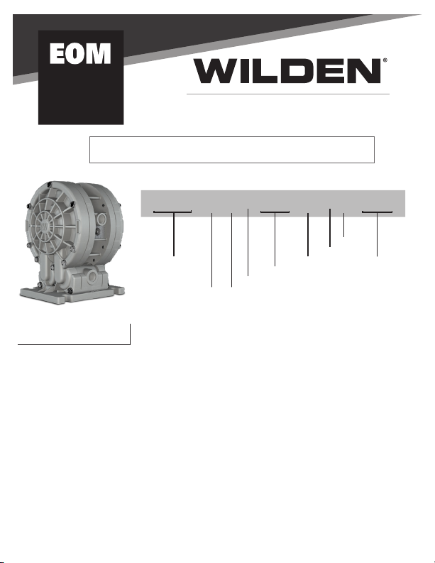
PUMP DESIGNATION SYSTEM
V2550/ XXX XX /XXX / XX/ XXX/ XXXX
MODEL
WETTED PAR TS &
OUTER PISTON
MATERIAL CODES
MODEL
V2550 = 6 mm (1/4”) VELOCITY
A2550V = 6 mm (1/4”) ACCU-FLO™
WETTED PARTS & OUTER PISTON
KK = PVDF / PVDF
PP = POLYPROPYLENE / POLYPROPYLENE
AIR CHAMBER / CENTER BLOCK
PP = POLYPROPYLENE
AIR VALVE
A = ALUMINUM (ACCU-FLO Only)
E = PET
LEGEND
O-RINGS
SPEC IALTY
CODE
(if applicable )
DIAPHRAGMS
AIR VA LVE
CENTER SECTION
VALVE S EAT
VALVE B ALLS
DIAPHRAGMS
TSS = FULL-STROKE PTFE W/ SANIFLEX
BACK-UP O-RING
ZWS = WIL-FLEX™ [Santoprene
®
(Three Black Dots)]
VALVE BALLS
TF = PTFE (White)
WF = WIL-FLEX™ [Santoprene
®
(Three Black Dots)]
VALVE SEAT
K = KYNAR
P = POLYPROPYLENE
VALVE SEAT O-RING
TV = PTFE-ENCAP. FKM
WF = WIL-FLEX (Santoprene
®
)
SPECIALTY CODES
0150 Accu-Flo, 24V DC Coil
0151 Accu-Flo, 24V AC/12V Coil
0155 Accu-Flo, 110V AC Coil
Page 2
CAUTIONS & WARNINGSBASIC TROUBLESHOOTINGSUGGESTED INSTALLATION
PUMP TEMPERATURE LIMITS:
PVDF and Polypropylene 4°C – 79°C (40°F - 175°F)
CAUTION: Maximum temperature limits are based upon mechanical
stress only. Certain chemicals will signifi cantly reduce maximum
safe operating temperatures. Consult Chemical Resistance Guide for
chemical compatibility and temperature limits.
CAUTION: Do not exceed 6.9 bar (100 psig) air supply pressure.
CAUTION: Verify the chemical compatibility of the process and cleaning
fl uid to the pump’s component materials in the Wilden Chemical
Resistance Guide.
CAUTION: Plastic series pumps are made from plastic that is not UV-
stabilized. Direct sunlight exposure for prolonged periods can cause
deterioration of plastic.
CAUTION: V2550 pumps are not submersible.
CAUTION: Always wear safety glasses when operating pump. If
diaphragm rupture occurs, fl uid being pumped may be forced out air
exhaust.
WARNING: Before any maintenance or repair is attempted, the
compressed air line to the pump should be disconnected and all air
pressure allowed to bleed from the pump.
WARNING: Ensure that the air supply line is clear of debris. Use of a 5µ
(micron) in-line air fi lter is recommended.
WIL-41000-E-06
Page 3
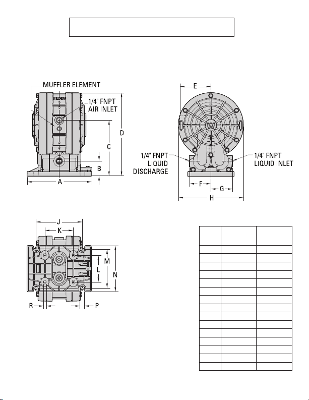
DIMENSIONAL DRAWING
DIMENSIONS
ITEM
A 138 5.4
B 32 1.3
C 119 4.7
D 177 7.0
E 66 2.6
F 46 1.8
G 46 1.8
H 138 5.4
J 98 3.9
K 60 2.4
L 57 2.2
M 83 3.3
N 98 3.9
P 10 0.4
R 6 0.2
METRIC
STANDARD
(mm)
(inch)
LW0351 REV. D
WIL-41000-E-06 WIL-41000-E-06
Page 4
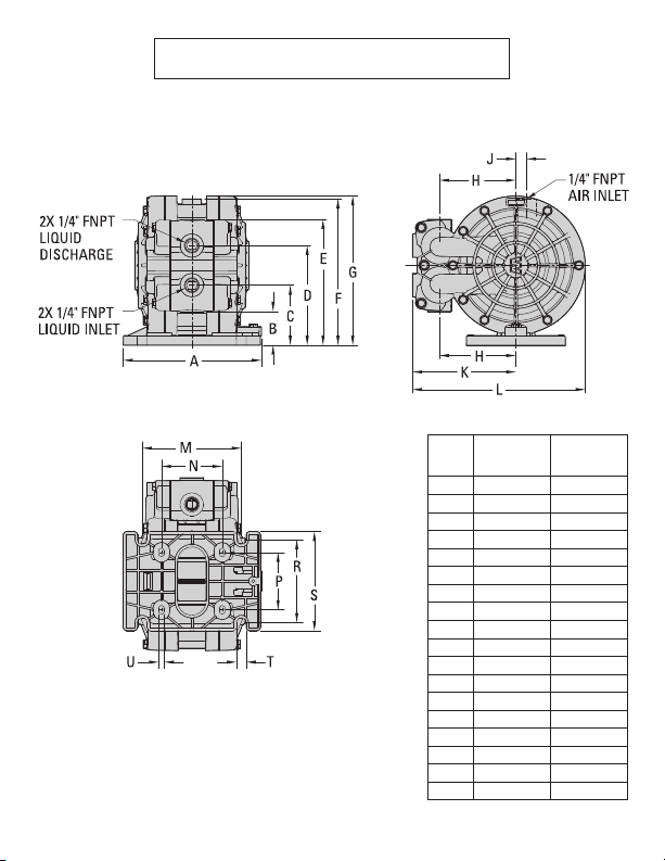
DIMENSIONAL DRAWING
V2550 PLASTIC - HORIZONTALV2550 PLASTIC
DIMENSIONS
METRIC
ITEM
A
B 34 1.3
C 60 2.4
D 99 3.9
E 125 4.9
F 145 5.7
G 148 5.8
H 76 3.0
J 11 0.4
K 103 4.1
L 172 6.8
M 98 3.9
N 60 2.4
P 57 2.2
R 83 3.3
S 98 3.9
T 10 0.4
U 6 0.2
STANDARD
(mm)
138 5.4
LW0352 REV. C
WIL-41000-E-06
(inch)
Page 5
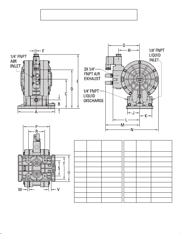
DIMENSIONAL DRAWING
A2550V PLASTIC
DIMENSIONS
METRIC
ITEM
A
B 32 1.3
C 108 4.3
D 143 5.6
E 201 7.9
F 5 0.2
G 116 4.6
H 78 3.1
J 46 1.8
K 46 1.8
STANDARD
(mm)
138 5.4
(inch)
ITEM
L 99 3.9
M 127 5.0
N 196 7.7
P 98 3.9
R 60 2.4
S 57 2.2
T 83 3.3
U 98 3.9
V 10 0.4
W 6 0.2
METRIC
(mm)
STANDARD
(inch)
LW0353 REV. D
WIL-41000-E-06
Page 6
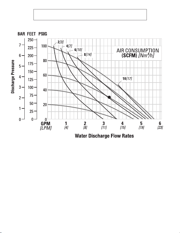
V2550 PERFORMANCE CURVE V2550 DRY SUCTION-LIFT CURVE
5[8]
4[7]
3[5]
.30+
.25
KEY
.20 .15
2[3]
1[2]
1 2 3 4
[4] [8] [11] [15]
Ship Weight .........................2 kg (4 lb)
Air Inlet ........................... 6 mm (1/4”)
Inlet .................................. 6 mm (1/4”)
Outlet ............................... 6 mm (1/4”)
Suction Lift ...............4.3 m Dry (14.2’)
6.2 m Wet (20.4’)
Disp. per Stroke1 ....... 0.04 L (0.01 gal)
Max. Flow Rate ....21.6 lpm (5.7 gpm)
Max. Size Solids ......... 0.8 mm (1/32”)
1
Displacement per stroke was
calculated at 4.8 bar (70 psig) air inlet
pressure against a 2.1 bar (30 psig)
head pressure.
Example: To pump 12.5 lpm (3.3 gpm)
against a discharge head of 2.1 bar
(30 psig) requires 4.1 bar (60 psig) and
10.4 Nm3/h (6.1 scfm) air consumption.
Caution: Do not exceed 6.9 bar (100
psig) air supply pressure.
Page 7
5[8]
4[7]
3[5]
.30+
.25
KEY
.20 .15
2[3]
1[2]
1 2 3 4
[4] [8] [11] [15]
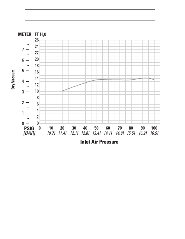
Suction-lift curves are created
using pumps operating at 305 m
(1000’) above sea level. This chart is
meant to be a guide only. There are
many variables which can affect the
pump’s operating characteristics.
Suction lift can be affected by
the number of intake/discharge
elbows, viscosity of pumping fl uid,
elevation (atmospheric pressure),
pipe friction losses and other
factors.
Caution: Do not exceed 6.9 bar (100
psig) air supply pressure.
WIL-41000-E-06
Page 8
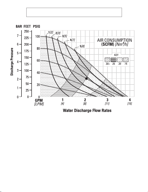
A2550V PERFORMANCE CURVE
5[8]
4[7]
3[5]
.30+
.25
KEY
.20 .15
2[3]
1[2]
1 2 3 4
[4] [8] [11] [15]
Ship Weight .........................2 kg (4 lb)
Air Inlet ........................... 6 mm (1/4”)
Inlet .................................. 6 mm (1/4”)
Outlet ............................... 6 mm (1/4”)
Suction Lift ...............4.3 m Dry (14.2’)
6.2 m Wet (20.4’)
Disp. per Stroke1 ....... 0.04 L (0.01 gal)
Max. Flow Rate ....14.8 lpm (3.9 gpm)
Max. Size Solids ......... 0.8 mm (1/32”)
1
Displacement per stroke was
calculated at 4.8 bar (70 psig) air inlet
pressure against a 2.1 bar (30 psig)
head pressure.
Example: To pump 7.9 lpm (2.1 gpm)
against a discharge head of 2.1 bar (30
psig) requires 4.1 bar (60 psig) and 6.6
Nm3/h (3.9 scfm) air consumption.
Caution: Do not exceed 6.9 bar (100
psig) air supply pressure.
Page 9
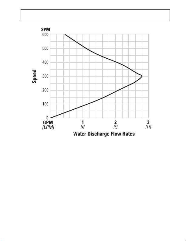
A2550V 70/30 OPERATING CONDITION
This curve demonstrates the fl ow created when the stroke rate is varied
under static air and fl uid pressure conditions. This curve can be applied
to different pressure conditions to estimate the change in fl ow due to
stroke rate.
WIL-41000-E-06WIL-41000-E-06WIL-41000-E-06
Page 10

SUGGESTED INSTALLATION
PUMP SELECTION: Ensure that the pump materials of construct ion are compa tible with
the pumping media and the immediate surrou ndings the pump will be subject ed to. Refer to the
Wilden Che mical Resis tance Guide . For optimum li fe and perf ormance, the pump s ize should be
speci fi e d so that dai ly operat ion param eters ar e not near th e pump’s max imum rat ed perfo rmance
capabilities.
INSTALLATION: The Velocit y pump has two foot-mount confi gurations and can be mounted
in any or ientat ion. The pump can be mount ed in place or lef t free standing for use in multiple
locat ions. If t he pump is to be mount ed in place, it is suggested to at tach the Base Assembly to
the desired horizont al or vertical surface using four ( 4) screws (not supplied ) and then at tach the
pump to the Base Assembly (See Assembly Ins tructions).
The Velocity pump has two inlet fl uid connections and two discharge fl uid connections. One inlet
and discharge connec tion must b e plugged using the supplied NPT plugs.
PIPING: The suction and discharge piping diameter should be equivalent or larger t han the
diame ter of pump connect ion, the length and complexit y of the suct ion and discharge piping
shoul d be minimized, unnecessary elbow s, bends and fi t tings should be avoided, all in an e ff ort
to reduce friction los ses.
The suction hose must be non- collapsible. If rigid piping is used , it should be supported
independen tly of the pump. I n addition, the piping should be aligned to avoid placing s tre ss on
the pump fi t tings.
Whe n used in self -primi ng applicat ions, it i s critic al that all fi tting s and connec tions are ai rtigh t or
a reduc tion or loss of pump suct ion capabili ty will r esult. E nsure that the suctio n lift requirement
is within the pump model’s capabilit y.
AIR SUPPLY: Every pump should have an airline large enough to supply the volume of air
necessary to achieve the desir ed pumping rate. Air pr essure to t he pump shoul d not exceed a
maximum of 6.9 bar (10 0 psig ). For best results, t he pumps should use a 5µ (micron) air fi lter to
eliminate air-li ne contaminant s, a needle valve and p ressure regulator.
SOLENOID CONTROL: When s tar t-s top operation of a st andard air val ve equipped pump is
cont rolled by a so lenoid valve in the air line, a thr ee-way ( 3/2 ) solenoid valve sh ould be used to
vent pressurized air be tween the solenoid and pump w hen the pump is stopped.
PUMP OPERATION : Once ins tallation is complete, pump operation can be s tar ted by opening
the ai r shut-o ff val ve (do no t exceed the p ump’s max imum ra ted pres sure) . The pr essure r egulato r
and needle valve are used to adjust the speed of t he pump.
WIL-41000-E-06 WIL-41000-E-06
Page 11

BASIC TROUBLESHOOTINGSUGGESTED INSTALLATION
Pump will not run or runs slowly:
1. Ensure the air inlet pressure is 0.3 bar (5 psig) above the start-up pressure of
the pump.
2. Ensure the differential pressure (dif ference b etween the air inle t pres sure and
fl uid discharge pre ssure) is not less than 0.7 bar (10 psig) .
3. Check air line /fi lter for blo ckage/ debris. Check for obstruc tion in the air
passageways of the p ump.
4. Check for objects in the pump that would obs truct the movement of internal parts.
5. Check for severe air leakage (blow -by) c oming f rom the air exhaust. This could
indicate a failed O-ring s eal or worn air valve assembly.
6. Inspe ct for check valve failure. A worn check ball can get stuck in the seat. A chec k
ball can swell and bec ome stuck if not compatible with fl uid pumpe d. Replace if
nece ss ar y.
Pump runs but little or no product fl ows:
1. Check for cavitation. Confi rm vac uum required to lif t the fl uid is not greater than
the vapor pres sure of the fl uid being pumped. Slow pump spe ed to allow viscous
fl uids to fl ow into liquid chambers.
2. Ensure that the suction lift requirement is within the pump model’s capability.
3. Inspect for check valve f ailure. A worn check ball can get stuck in the seat . A check
ball can swell and bec ome stuck if not compatible with fl uid pumpe d. Replace if
nece ss ar y.
Air bubbles in pump discharge:
1. Check for ruptured diaphragm.
2. Check tightness of outer piston to shaft.
3. Check integrity of O -ring seals, especially intake side of manifold.
4. Ensure pipe connections are airtight.
Product comes out of air exhaust:
1. Check for ruptured diaphragm.
2. Check tightness of outer piston to shaft.
Page 12
DISASSEMBLY / REASSEMBLY ELASTOMER OPTIONS
Tools Required:
• 5 /16” Socket Wrench
• 7/16” Socket Wr ench
• Snap-Ring Pliers
1. Insert t he smaller end o f the air valve
assembly (item 1) into center section
(ite m 5) until fully seated. Ins tall
reta ining r ing (it em 6) in groove o n air
valve assembly.
2. Install b acku p O-r ings (item 20 ) on to
surface s of cen ter se ctio n (ite m 5).
3. Slide washe r (ite m 18) and i nner pi ston s
(ite m 19) on to e nds of shaft.
4. Slide dia phragms (item 21) on to e nds
of shaf t.
5. Install ou ter pistons (item 22) on to e nds
of shaf t. Tighte n to spe cifi ed torque ( 50
lb-in). O ver-tighte ning co uld dam age
outer piston.
6. Ins tall f our (4 ) ball ch eck c artridge s
(ite m 15) into m anifo ld (it em 13) . NOTE:
The ca rtr idges must b e inst alled in
corr ect or ient ation. Align groove s on
car tridge with r ibs in ma nifold. Car tridge will b e fl u sh wit h end of th e manif old if in stalled co rrec tly.
CAUTI ON : Bef ore an y main tenance or repair is a tt empt ed, t he
compr essed air li ne to the pump s houl d be disconnec ted and all air
pres sure allow ed to bleed f rom the pum p.
7. Install four ( 4) man ifold O-rings (i tem 16) o n to end s of mani fold (item 13).
8. P lace u pper s crew b oss in m anifo ld (it em 13) in -be twe en the fl ange s at the b ottom of the c ente r sec tion
(item 5).
9. Place the center section-ma nifol d asse mbly b etw een t wo liqu id cham bers ( item 12), taking care to ali gn
the lar ge bor e on liqui d chamb er over t he diap hragm a nd the t wo (2 ) small b ores over the manifold.
10. Place in a vise an d care full y pres s assembly t oget her. Take care not to pinch or da mage sealing O -ri ngs.
Ther e shoul d be a con sistent 0. 05” gap be tween the c ente r sec tion (item 5 ) and liquid chamber s (ite m
12) .
11. Fas ten liquid chamber s (it em 12) to ce nter s ection (it em 5) an d manif old (i tem 13) u sing ( 22) #10 s crew s
(ite m 10). T ighten fas tene rs to sp ecifi ed torque (35 lb -in ). Over-tig hteni ng fas tene rs could dama ge
center section.
12. Pres s muf fl er e lement (item 9) in to muf fl er c avit y (near air inlet) o f cent er sec tion ( item 5 ). Ho ld muf fl er
element in place us ing one (1) # 10 scre w (ite m 10).
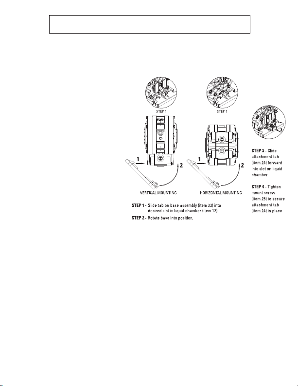
13. There ar e two mountin g options for t he bas e asse mbly ( item 2 3).
14. Install on e (1) NPT pl ug (it em 14) int o one (1) inl et por t of the manifold (it em 13) . Inst all one (1) NPT plug
into on e (1) disc harge p ort o n manif old.
WIL-41000-E-06
Page 13
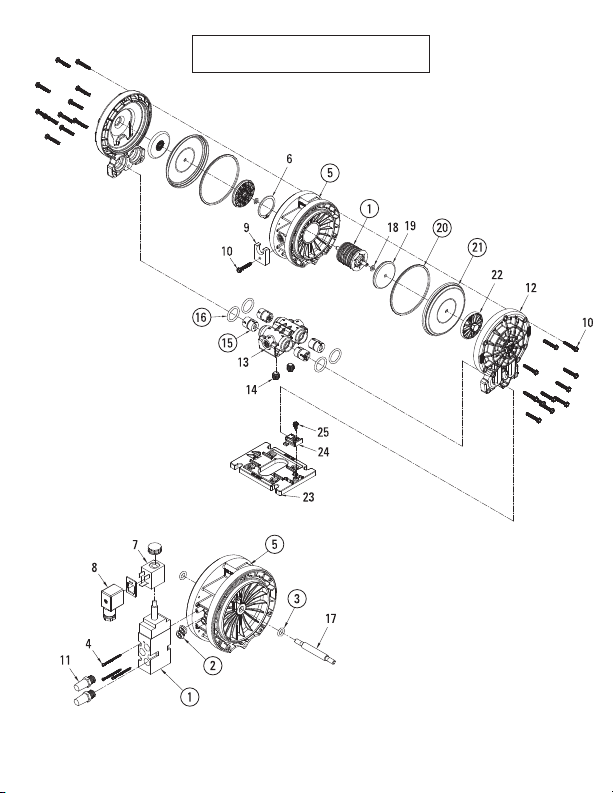
ACCU-FLO™
ALL CIRCLED PART IDENTIFIERS ARE INCLUDED IN REPAIR KITS
LW0355 REV. D
WIL-41000-E-06
Page 14
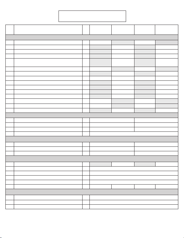
PARTS LISTINGEXPLODED VIEW
Item
1 Air Valve Assembly
Air Valve Assembly, Solenoid
2 Gasket, Solenoid Valve 1
3 O-Ring, Shaft (-110, Ø.362" x Ø.103") 2
Screw, Hex Washer Head Torx, Solenoid Air
4
Valve (#4-24 x 1 1/4")
5 Center Section Assembly, Air Valve
Center Section Assembly, Accu-Flo
6 Retaining Ring 1
7 Coil, 24V DC 1
Coil, 24V AC / 12V DC 1
Coil, 110V AC 1
8 Connector, Solenoid 1
9 Muffl er Element 1
10
Screw, Hex Washer Head Tri-Lobe (#10-14 x 1-1/4")100-6114-03 00-6114-03
11 Muffl er, 1/4" MNPT 2
12 Liquid Chamber 2
13 Manifold, Four Port, 1/4" (NPT) 1
14 Manifold Pipe Plug 1/4" (NPT) 2
10
Screw, Hex Washer Head Tri-Lobe (#10-14 x 1-1/4")
Description Qty.
1
AIR DISTRIBUTION COMPONENTS
2
3
4
™
WETTED PATH COMPONENTS
V2550
/PPPPE/…/P/N
1
00-2044-99 00-2044-99
1
3
1
00-3171-20 00-3171-20
1
00-2644-09 N/A 00-2644-09 N/A
00-3244-26 00-3244-26
22
A2550V
/PPPPA/…/P/N
00-2014-99 00-2014-99
00-2640-56 00-2640-56
15-2650-49 15-2650-49
00-6134-03 00-6134-03
00-3169-20 00-3169-20
00-2110-99-150 00-2110-99-150
00-2110-99-151 00-2110-99-151
00-2110-99-155 00-2110-99-155
00-2130-99 00-2130-99
04-3240-07 04-3240-07
00-5014-20 00-5014-21
00-5164-20 00-5164-21
00-7014-20 00-7014-21
00-6114-03
BALL CHECK CARTRIDGE / MANIFOLD ORINGS
15
Ball Check Cartridge
16
Manifold O-Ring, TPE Fitted (-214, Ø.984 x Ø.139")
Manifold O-Ring, PTFE Fitted (-214, Ø.984 x Ø.139")
4
4
4
* *
* *
* *
FULLSTROKE RUBBER / TPE / PTFE COMPONENTS
17 Shaft 1
18
Washer, Inner Piston (Ø.255" x Ø.468" x .060")
19
Piston, Inner
20 Diaphragm, Back-Up Seal PTFE only 2
21 Diaphragm, Primary 2
22 Piston, Outer 2
23
Base, Removable Assembly
24
Attachment Tab, Removable Base
25
Screw, Slotted Hex Washer Head Tapping (#10-12 x 1/2")
* See Elastomer Options
1 Air Valve Assembly includes item
6 and 9.
2
Accu-Flo™ Air Valve Assembly
includes items 2, 4, 7, 8 and 11.
REMOVABLE FOOT COMPONENTS
5
3 Air Valve Center Section Assembly includes items
1, 6, 9 and 10.
4 Accu-Flo™ Center Section Assembly includes
items 1, 2, 3, 4, 7, 8, 11 and 17.
5 Removable Base Assembly includes items 24 and 25.
2
2
00-4640-20 00-4640-20 00-4640-21 00-4640-21
1
1
1
00-3849-03 00-3849-03
00-6844-03
00-3740-20
00-5540-99
00-5544-20
00-6124-03
V2550
/KKPPE/…/P/N
*
*
All boldface
items are
primary wear
parts.
WIL-41000-E-06
A2550V
/KKPPA/…/P/N
LW0356 Rev. F
Page 15
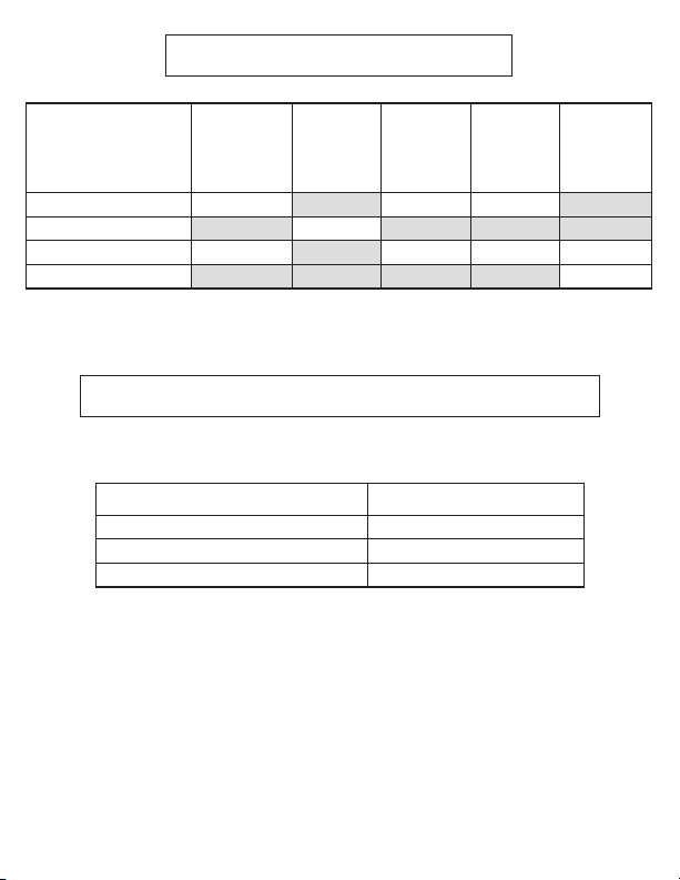
ELASTOMER OPTIONS
MATERIAL
PTFE
Sanifl ex™
Wil-Flex™
PTFE-Encapsulated FKM
DIAPHRAGM
DIAPHRAGMS
(2)
00-1044-55 00-9189-55 00-9188-55
00-1044-58 00-9189-58 00-9188-58 38-1371-58
BACK-UP
SEAL
00-1074-56
POLY BALL
CHECK
CARTRIDGE
(2)
(4)
MAXIMUM TORQUE SPECIFICATIONS
VELOCITY MAXIMUM TORQUE SPECIFICATIONS
Description of Par t Torque
Liquid Chamber – Center Section (#10) 4.5 N•m (40 in-lb)
Outer Piston 5.6 N•m (50 in-lb)
Solenoid - Center Section (#4) 1.6 N•m (15 in-lb)
PVDF BALL
CHECK
CARTRIDGE
(4)
MANIFOLD
O-RINGS
(4)
38-1371-60
LW0356 Rev. F
WIL-41000-E-06WIL-41000-E-06
Page 16
WARRANTY
Each and every product manufactured by Wilden Pump & Engineering, LLC is built
to meet the highest standards of quality. Every pump is functionally tested to insure
integrity of operation. Wilden Pump & Engineering, LLC warrants that pumps,
accessories and parts manufactured or supplied by it to be free from defects in
material and workmanship for a period of fi ve (5) years from date of installation or
six (6) years from date of manufacture, whichever comes first. Failure due to normal
wear, misapplication, or abuse is, of course, excluded from this warranty. Since
the use of Wilden pumps and parts is beyond our control, we cannot guarantee
the suitability of any pump or part for a particular application and Wilden Pump
& Engineering, LLC shall not be liable for any consequential damage or expense
arising from the use or misuse of its products on any application. Responsibility
is limited solely to replacement or repair of defective Wilden Pump & Engineering,
LLC. All decisions as to the cause of failure are the sole determination of Wilden
Pump & Engineering, LLC. Prior approval must be obtained from Wilden for
return of any items for warranty consideration and must be accompanied by the
appropriate MSDS for the product(s) involved. A Return Goods Tag, obtained from
an authorized Wilden distributor, must be included with the items which must be
shipped freight prepaid. The foregoing warranty is exclusive and in lieu of all other
warranties expressed or implied (whether written or oral) including all implied
warranties of merchantability and fitness for any particular purpose. No distributor
or other person is authorized to assume any liability or obligation for Wilden Pump
& Engineering, LLC other than expressly provided herein.
22069 VAN BUREN STREET • GRAND TERRACE, CA 92313-5607
(909) 422-1700 • FAX (909) 783-3440
www.wildenpump.com
WIL-41000-E-06
 Loading...