

Page 1
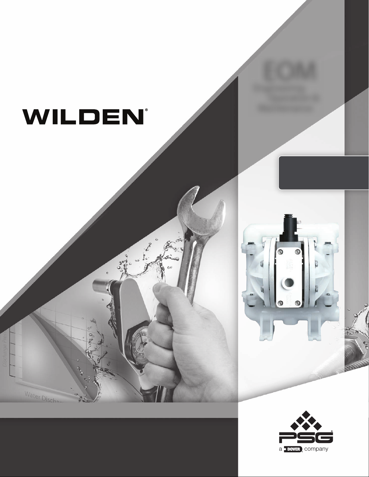
EOM
Engineering
Operation &
Maintenance
A100
Plastic Pump
Where Innovation Flows
wildenpump.com
Page 2
TABLE OF CONTENTS
SECTION 1 CAUTIONS—READ FIRST! ..............................................1
SECTION 2 WILDEN PUMP DESIGNATION SYSTEM .................................2
SECTION 3 DIMENSIONAL DRAWINGS .............................................3
SECTION 4 PERFORMANCE
A100 Plastic Rubber-Fitted ..................................................4
A100 Plastic PTFE-Fitted ....................................................4
Suction- Lift Curves .......................................................5
SECTION 5 EXPLODED VIEW & PARTS LISTING .....................................6
SECTION 6 ELASTOMER OPTIONS ..................................................8
Page 3
Section 1
CAUTION–READ FIRST!
TEMPERATURE LIMITS:
Acetal –29°C to 82°C –20°F to 180°F
Buna-N –12°C to 82°C 10°F to 180°F
Geolast
®
–40°C to 82°C –40°F to 180°F
Neoprene –18°C to 93°C 0°F to 200°F
Nordel
®
EPDM –51°C to 138°C –60°F to 280°F
Nylon –18°C to 93°C 0°F to 200°F
PFA –7°C to 107°C 45°F to 225°F
Polypropylene 0°C to 79°C 32°F to 175°F
Polyurethane –12°C to 66°C 10°F to 150°F
PVDF –12°C to 107°C 10°F to 225°F
Saniflex™ –29°C to 104°C –20°F to 220°F
SIPD PTFE with EPDM-backed
SIPD PTFE with Neoprene-backed
PTFE
1
4°C to 104°C 40°F to 220°F
4°C to 137°C 40°F to 280°F
4°C to 93°C 40°F to 200°F
FKM –40°C to 177°C –40°F to 350°F
Wil-Flex™ –40°C to 107°C –40°F to 225°F
1
4°C to 149°C (40°F to 300°F) - 13 mm (1/2") and 25 mm (1") models only.
NOTE: Not all materials are available for all
models. Refer to Section 2 for material options for
your pump.
CAUTION: When choosing pump materials, be
sure to check the temperature limits for all wetted
components. Example: FKM has a maximum
limit of 177°C (350°F) but polypropylene has a
maximum limit of only 79°C (175°F).
CAUTION: Maximum temperature limits are
based upon mechanical stress only. Certain
chemicals will significantly reduce maximum safe
operating temperatures. Consult engineering
guide for chemical compatibility and temperature
limits.
CAUTION: Plastic pumps are made with plastic
that is not UV-stabilized. Direct sunlight for
prolonged periods can cause deterioration of
plastics.
CAUTION: Before any maintenance or repair is
attempted, the compressed air line to the pump
should be disconnected and all air pressure
allowed to bleed from pump. Disconnect all
intake, discharge and air lines. Drain the pump
by turning it upside down and allowing any fluid
to flow into a suitable containe.
CAUTION:
Blow out air line for 10 to 20 seconds
before attaching to pump to make sure all pipe line
debris is clear. Use an in-line air filter. A 5µ (micron)
air filter is recommended.
NOTE: Tighten all bolts prior to installation.
Fasteners may loosen during transportation.
NOTE: When installing PTFE diaphragms, it is
important to tighten outer pistons simultaneously
(turning in opposite directions) to ensure tight fit.
CAUTION: Verify the chemical compatibility of
the process and cleaning fluid to the pump’s
component materials in the Chemical Resistance
Guide.
CAUTION: When removing the end cap using
compressed air, the air valve end cap may come
out with considerable force. Hand protection
such as a padded glove or rag should be used to
capture the end cap.
CAUTION: Always wear safety glasses when
operating pump. If diaphragm rupture occurs,
material being pumped may be forced out air
exhaust.
WARNING : Prevent static sparking. If static
sparking occurs, fire or explosion could result.
CAUTION: Do not over-tighten the air inlet
reducer bushing. Additionally, too much torque
on the muffler may damage the air valve muffler
plate.
CAUTION:
The A100 plastic pump is not
submersible.
Proper grounding of pump, valves, and cont ainers
is critical when handling flammable fluids and
whenever discharge of static electricity is a
hazard.
CAUTION : Only explosion proof (NEMA 7) solenoid
valve should be used in areas where explosion proof
equipment is required.
CAUTION: Do not exceed 8.6 bar (125 psig) air
supply pressure.
WIL-11040-E-06 1 WILDEN PUMP & ENGINEERING, LLC
Page 4
Section 2
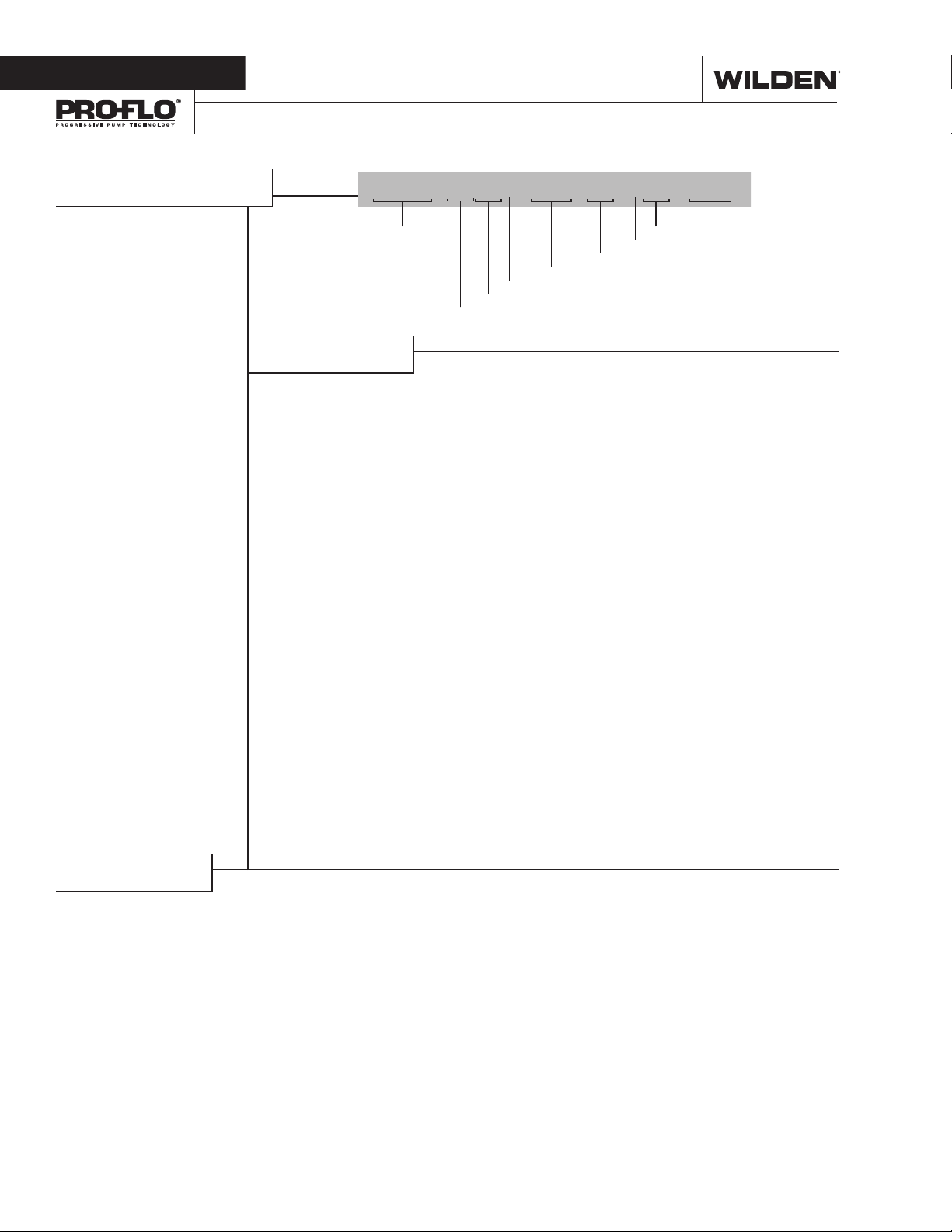
WILDEN PUMP DESIGNATION SYSYTEM
A100 PLASTIC
13 mm (1/2”) Pump
Maximum Flow Rate:
42.4 lpm (11.2 gpm)
LEGEND
A100P / XX XXX / XXX / XX / XXX / XXXX
MODEL
MATERIAL CODES
AIR SYSTEM BASE TYPE
P = PRO-FLO®
B = ADAPTER BLOCK
WETTED PARTS & OUTER
PISTON
KK = PVDF / PVDF
PP = POLYPROPYLENE /
POLYPROPYLENE
CENTER SECTION
PP = POLYPROPYLENE
AIR VALVE
P = POLYPROPYLENE
DIAPHRAGMS
VALVE BALLS
AIR VALVE
CENTER SECTION
WETTED PAR TS & OUTER PISTON
DIAPHRAGMS
BNS = BUNA-N (Red Dot)
FSS = SANIFLEX™ [Hytrel®
(Cream)]
PUS = POLYURETHANE
(Clear)
THU = PTFE W/HIGH-TEMP
BUNA-N BACKUP
(White)
TNL = PTFE W/NEOPRENE
BACKUP O-RING, IPD
(White)
TNU = PTFE W/NEOPRENE
BACKUP (White)
VTS = FKM (White Dot)
WFS = WIL-FLEX™
[Santoprene®
(Three Black Dots)]
O-RINGS
VALVE SE ATS
VALVE BALLS
BN = BUNA-N (Red Dot)
FS = SANIFLEX™
PU = POLYURETHANE
TF = PTFE (White)
VT = FKM (White Dot)
WF = WIL-FLEX™
VALVE SEATS
K = PVDF
P = POLYPROPYLENE
VALVE SEAT O-RINGS
BN = BUNA-N
FS = SANIFLEX™
PU = POLYURETHANE
TV = PTFE ENCAP. FKM
WF = WIL-FLEX™
SPECIALT Y
CODE
(if applicable)
[Hytrel® (Cream)]
(Brown)
[Santoprene®
(Three Black Dots)]
[Hytrel® (Cream)]
(Brown)
(Santoprene®)
SPECIALTY CODES
0150 Accu-Flo™, 24V DC coil
0151 Accu-Flo™, 24V AC / 12V DC coil
0155 Accu-Flo™, 110V AC coil
0160 Accu-Flo™, 24V DC coil, BSPT
0512 Adapter block, no muffler, Pro-Flo
0682 P100 with OEM manifold, Accu-Flo™ 24V DC Coil
NOTE: Most elastomeric materials use colored dots for identification.
WILDEN PUMP & ENGINEERING, LLC 2 WIL-11040-E-06
®
, center section
Page 5
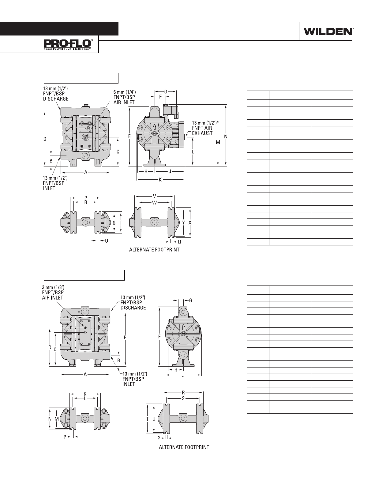
Section 3
DIMENSIONAL DRAWINGS
A100 PLASTIC
DIMENSIONS
ITEM METRIC (mm) STANDARD (inch)
A 234 9.2
B 51 2.0
C 135 5.3
D 254 10.0
E 279 11.0
F 51 2.0
G 102 4.0
H 79 3.1
J 142 5.6
K 226 8.9
L 137 5.4
M 224 8.8
N 277 10.9
P 145 5.7
R 114 4.5
S 91 3.6
T 102 4.0
U 8 0.3
V 188 7.4
W 155 6.1
X 140 5.5
Y 130 5.1
A100B PLASTIC
DIMENSIONS
ITEM METRIC (mm) STANDARD (inch)
A 234 9.2
B 51 2.0
C 157 6.2
D 180 7.1
E 254 10.0
F 279 11.0
G 25 1.0
H 66 2.6
J 168 6.6
K 145 5.7
L 114 4.5
M 91 3.6
N 102 4.0
P 8 0.3
R 188 7.4
S 155 6.1
T 140 5.5
U 130 5.1
WIL-11040-E-06 3 WILDEN PUMP & ENGINEERING, LLC
Page 6
.5+ .4
.25 .2
.3
[Nm3/h]
[LPM]
Section 4
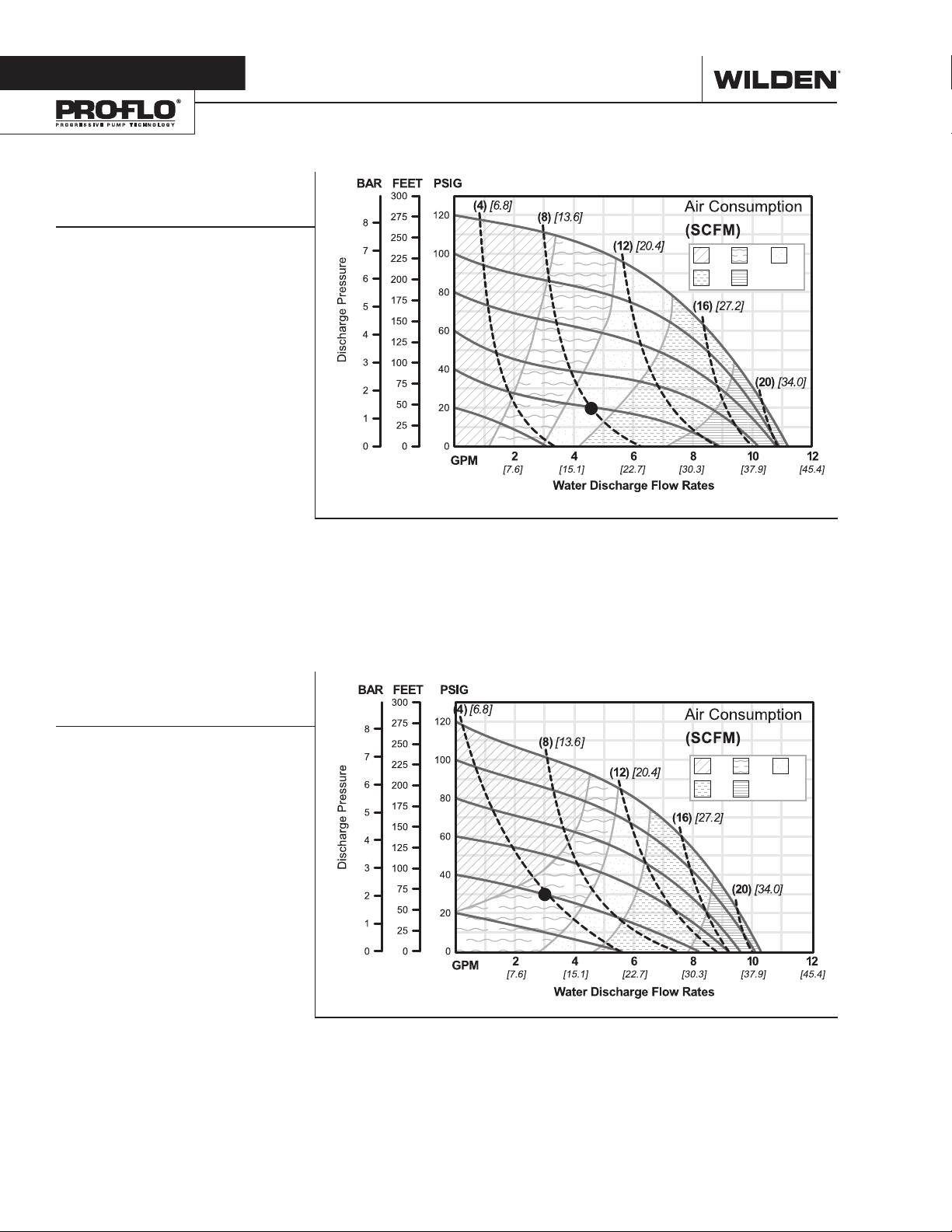
PERFORMANCE
A100 PLASTIC
RUBBER-FITTED
Est. Ship Weight .........
Air Inlet ...................................... 6 mm (1/4")
Inlet ......................................... 13 mm (1/2")
Outlet ......................................13 mm (1/2")
Suction Lift ........................ Dry 6.6 m (21.5')
Disp. Per Stroke¹ .............. 0.11 L (0.03 gal)
Max. Flow Rate ............... 42.4 lpm (11.2 gal)
Max. Size Solids ...................1.6 mm (1/16")
1
Displacement per stroke was calculated at 4.8 bar
(70 psig) air inlet pressure against a 2.0 bar (30
psig) head pressure.
Example: To pump 17.4 lpm (4.6 gpm)
against a discharge head pressure of 1.4
bar (20 psig) requires 2.8 bar (40 psig) and
3
13.6 Nm
/h (8 scfm) air consumption. (See
dot on chart.)
Caution: Do not exceed 8.6 bar (125 psig) air
supply pressure.
Polypropylene 4 kg (8 lb)
PVDF 5 kg (10 lb)
Wet 9.0 m (29.5')
[Nm3/h]
.5+ .4
.25 .2
.3
Flow rates indicated on chart were determined by pumping water.
For optimum life and performance, pumps should be specified so that daily operation parameters
will fall in the center of the pump’s performance curve.
[LPM]
A100 PLASTIC
PTFE-FITTED
Est. Ship Weight .........
Air Inlet ...................................... 6 mm (1/4")
Inlet ......................................... 13 mm (1/2")
Outlet ......................................13 mm (1/2")
Suction Lift ........................ Dry 5.7 m (18.7')
Disp. Per Stroke¹ .............. 0.11 L (0.03 gal)
Max. Flow Rate ............... 38.2 lpm (10.1 gal)
Max. Size Solids ...................1.6 mm (1/16")
1
Displacement per stroke was calculated at 4.8 bar
(70 psig) air inlet pressure against a 2.0 bar (30
psig) head pressure.
Example: To pump 11.4 lpm (3.0 gpm)
against a discharge head pressure of 2.1
bar (30 psig) requires 2.8 bar (40 psig) and
3
6.8 Nm
/h (4 scfm) air consumption. (See dot
on chart.)
Caution: Do not exceed 8.6 bar (125 psig) air
supply pressure.
Polypropylene 4 kg (8 lb)
PVDF 5 kg (10 lb)
Wet 9.3 m (30.6')
[Nm3/h]
.5+ .4
.25 .2
[LPM]
Flow rates indicated on chart were determined by pumping water.
For optimum life and performance, pumps should be specified so that daily operation parameters
will fall in the center of the pump’s performance curve.
.3
WILDEN PUMP & ENGINEERING, LLC 4 WIL-11040-E-06
Page 7
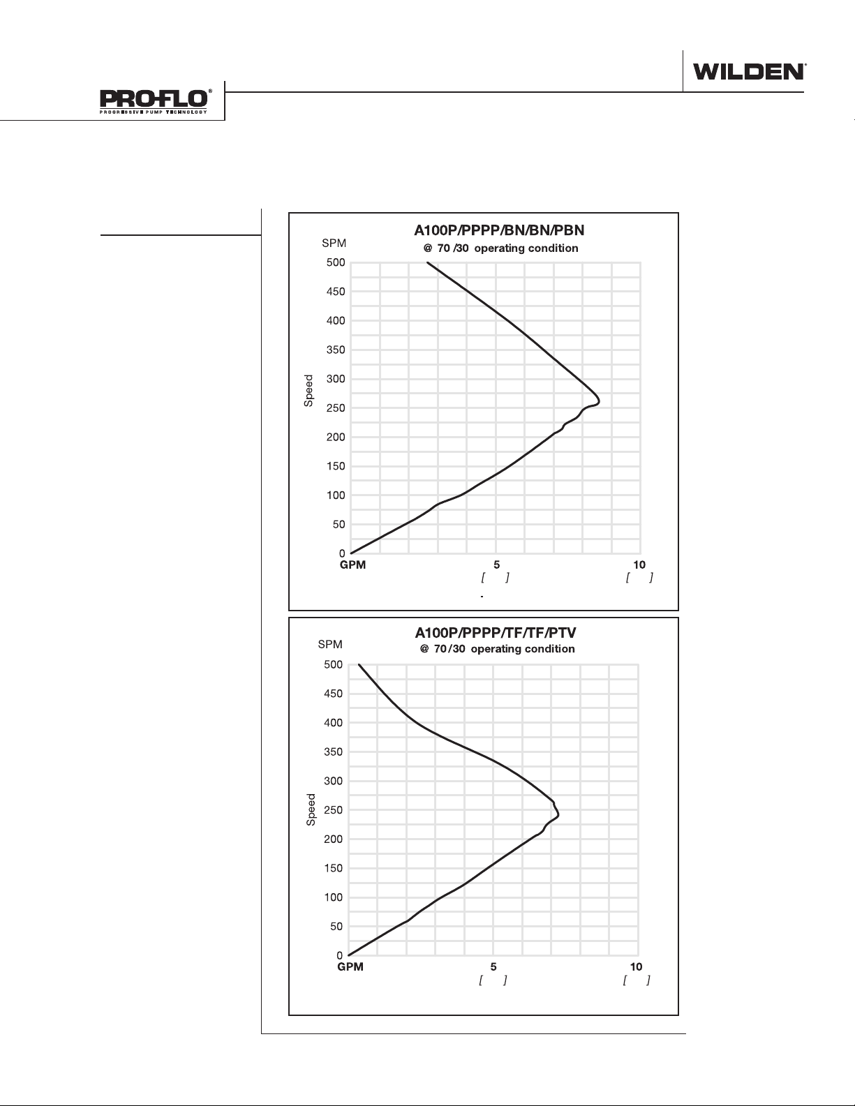
SUCTION-LIFT CURVES
These curves demonstrate the flow created when the stroke rate is modified under static air and fluid pressure condition. This curve can be applied to different pressure conditions to estimate the change in flow due to stroke rate.
A100 PLASTIC
[LPM]
[LPM]
18.9 37.9
Water Discharge Flow Rate
18.9 37.9
Water Discharge Flow Rate
WIL-11040-E-06 5 WILDEN PUMP & ENGINEERING, LLC
Page 8
Section 5
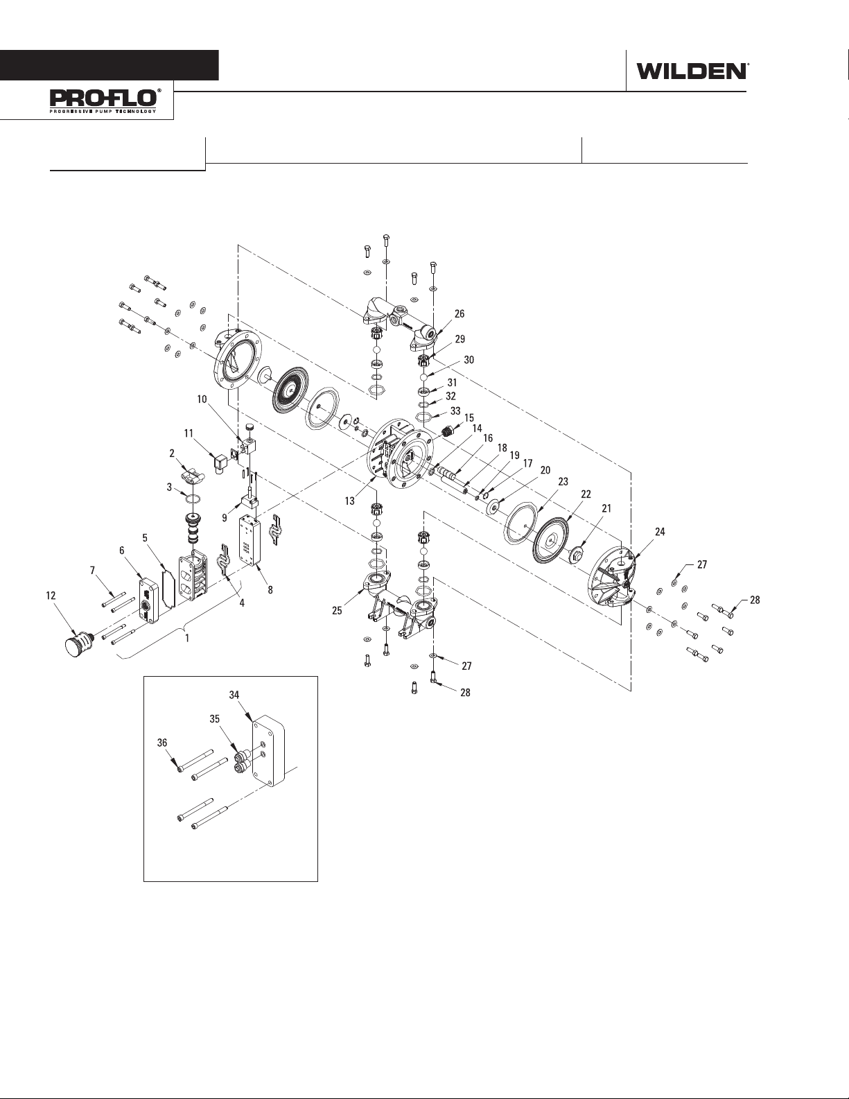
EXPLODED VIEW & PARTS LISTING EXPLODED VIEW & PARTS LISTING
A100 PLASTIC
EXPLODED VIEW
ADAPTER BLOCK VERSION
WILDEN PUMP & ENGINEERING, LLC 6 WIL-11040-E-06
Page 9
EXPLODED VIEW & PARTS LISTING
A100 PLASTIC
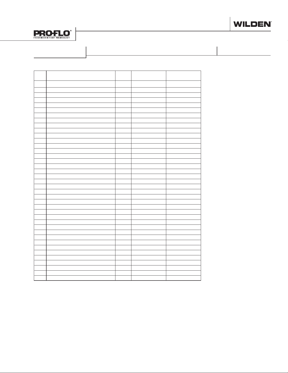
Item Description Qty.
1 Air Valve Assembly
2 End Cap 1 01-2332-20 01-2332-20
3 O-ring, (.103 x 1.362) 1 01-2395-52 01-2395-52
4 Gasket, Air Valve 2 01-2615-52 01-2615-52
5 Gasket, Muffler Plate 1 01-3505-52 01-3505-52
6 Muffler Plate 1 01-3181-20 01-3181-20
7 Air Valve Screws, SHC, 1/4-20 x 4.5 4 01-6000-03 01-6000-03
8 Solenoid Spacer Plate 1 01-2160-20 01-2160-20
9 Operator, Solenoid, Nema 4 1 00-2120-99 00-2120-99
10 Coil 1 00-2110-99-151 00-2110-99-151
11 Terminal Connector 1 00-2130-99 00-2130-99
12 Muffler, 1/2” 1 02-3510-99 02-3510-99
13 Center Section 1 01-3141-20 01-3141-20
14 Glyd-Ring II, (.618 x .136) 2 01-3220-55 01-3220-55
15 Reducer Bushing 1 01-6950-20 01-6950-20
16 Pilot Plug Assy 1 01-2285-99 01-2285-99
17 Retaining Ring 2 00-2650-03 00-2650-03
18 Shaft 1 01-3810-03 01-3810-03
19 Disc Spring (.331 x .512) 2 01-6802-08 01-6802-08
20 Piston, Inner, (Combo) 2 01-3711-08 01-3711-08
21 Piston, Outer, (Combo) 2 01-4570-21-500 01-4570-21-500
22 Diaphragm, Primary, PTFE 2 01-1010-55 01-1010-55
23 Diaphragm, Back-Up, Neoprene 2 01-1060-51 01-1060-51
24 Liquid Chamber 2 01-5005-20 01-5005-21
25 Inlet Manifold 1 01-5095-20 01-5095-21
26 Discharge Manifold 1 01-5035-20 01-5035-21
27 Washer (.343 x .750 x .05) 24 01-6732-03 01-6732-03
28 Screw, HHC, 5/16-18 x 1.13 24 01-6191-03 01-6191-03
29 Ball Cage 4 01-5355-20 01-5355-21
30 Valve Ball 4 01-1080-55 01-1080-55
31 Valve Seat 4 01-1125-20 01-1125-21
32 Valve Seat O-ring (.924 x .103) 4 01-1205-60 01-1205-60
33 Manifold O-ring (1.484 x .139) 4 05-1370-60 05-1370-60
34 Adapter Block 1 01-2155-20 01-2155-20
35 Adapter Block Air Fittings 2 00-2170-20 00-2170-20
36 Air Valve Screws, SHC, 1/4-20 x 2 4 04-6000-03 04-6000-03
Alternate OEM Manifold (not shown) 1 01-5097-20 01-5097-21
Drum Pump Manifold (not shown) 1 01-5094-20 01-5094-21
Pipe Plug (not shown) 1 01-7101-20 01-7101-21
1
Air Valve Assembly includes items 2 & 3
All Boldface items are primary wear parts.
PTFE-FITTED
1
A100P/PKPPP/0151
P/N
1 01-2010-20 01-2010-20
A100P/KKPPP/0151
P/N
PARTS LISTING
WIL-11040-E-06 7 WILDEN PUMP & ENGINEERING, LLC
Page 10
Section 6
ELASTOMER OPTIONS
A100P & A100B PLASTIC
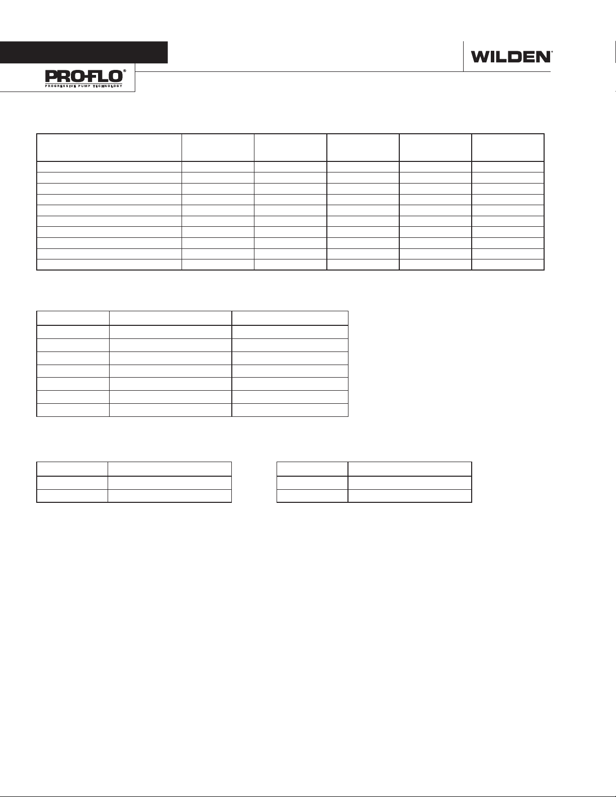
MATERIAL DIAPHRAGMS VALVE BALLS VALVE SEATS
Polyurethane 01-1010-50 01-1080-50 N/A 01-1200-50 02-1230-50
Buna-N 01-1010-52 01-1080-52 N/A 00-1260-52 02-1230-52
FKM 01-1010-53 01-1080-53 N/A N/A N/A
Wil-Flex™ 01-1010-58 01-1080-58 N/A 00-1260-58 01-1370-58
Saniflex™ 01-1010-56 01-1080-56 N/A 01-1200-56 01-1370-56
PTFE 01-1010-55 01-1080-55 N/A N/A N/A
PTFE with Integral Piston 01-1030-55 N/A N/A N/A N/A
Encapsulated/FKM N/A N/A N/A 01-1205-60 05-1370-60
PVDF N/A N/A 01-1125-21 N/A N/A
Polypropylene N/A N/A 01-1125-20 N/A N/A
VALVE SEAT
O-RINGS
MANIFOLD
O-RINGS
COIL OPTIONS
Specialty Code Part Number Description
150 00-2110-99-150 24V DC
154 00-2110-99-154 24V DC, NEMA 7
157 00-2110-99-157 24V DC, International
151 00-2110-99-151 24V AC/12V DC
153 00-2110-99-153 24V AC/12V DC, NEMA 7
155 00-2110-99-155 110V AC
156 00-2110-99-156 110V AC, NEMA 7
ADAPTER BLOCK OPTIONS
Part Number Description
01-2155-13 Acetal
01-2155-20 Polypropylene
OPERATOR OPTIONS
Part Number Description
00-2120-99 Nema 4
00-2121-99 Nema 7
WILDEN PUMP & ENGINEERING, LLC 8 WIL-11040-E-06
Page 11
WARRANTY
Each and every product manufactured by Wilden Pump and Engineering, LLC is built to meet the highest
standards of quality. Every pump is functionally tested to insure integrity of operation.
Wilden Pump and Engineering, LLC warrants that pumps, accessories and parts manufactured or supplied by
it to be free from defects in material and workmanship for a period of five (5) years from date of installation or
six (6) years from date of manufacture, whichever comes first. Failure due to normal wear, misapplication, or
abuse is, of course, excluded from this warranty.
Since the use of Wilden pumps and parts is beyond our control, we cannot guarantee the suitability of any pump
or part for a particular application and Wilden Pump and Engineering, LLC shall not be liable for any consequential
damage or expense arising from the use or misuse of its products on any application. Responsibility is limited
solely to replacement or repair of defective Wilden pumps and parts.
All decisions as to the cause of failure are the sole determination of Wilden Pump and Engineering, LLC.
Prior approval must be obtained from Wilden for return of any items for warranty consideration and must be
accompanied by the appropriate MSDS for the product(s) involved. A Return Goods Tag, obtained from an
authorized Wilden distributor, must be included with the items which must be shipped freight prepaid.
The foregoing warranty is exclusive and in lieu of all other warranties expressed or implied (whether written or oral)
including all implied warranties of merchantability and fitness for any particular purpose. No distributor or other
person is authorized to assume any liability or obligation for Wilden Pump and Engineering, LLC other than expressly
provided herein.
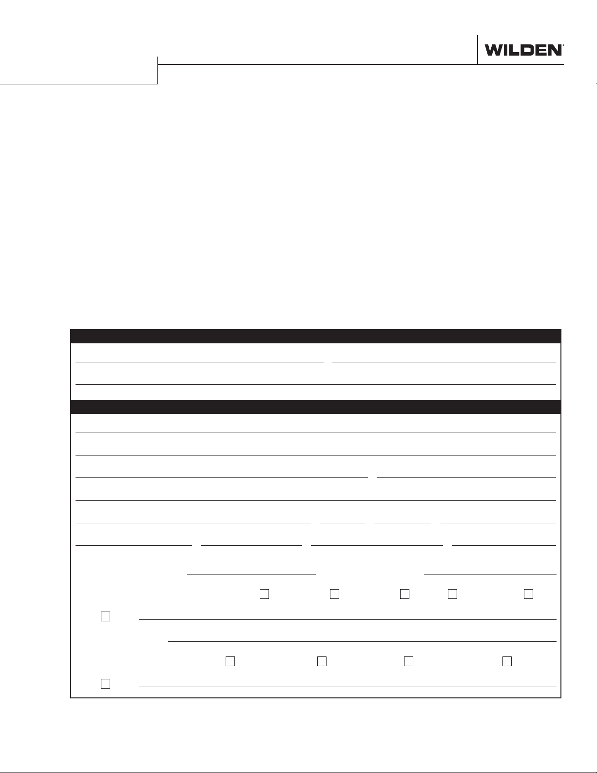
PLEASE PRINT OR TYPE AND FAX TO WILDEN
PUMP INFORMATION
Item # Serial #
Company Where Purchased
YOUR INFORMATION
Company Name
Industry
Name Title
Street Address
City State Postal Code Country
Telephone Fax E-mail Web Address
Number of pumps in facility? Number of Wilden pumps?
Types of pumps in facility (check all that apply): Diaphragm
Media being pumped?
Other
Centrifugal
Gear
Submersible
Lobe
How did you hear of Wilden Pump?
Other
Trade Journal
Trade Show
Internet/ E-mail
Distributor
ONCE COMPLETE, FAX TO (909) 783-3440
OR GO TO PSGDOVER.COM > WILDEN > SUPPORT TO COMPLETE THE WARRANTY REGISTRATION ONLINE
NOTE: WARRANTY VOID IF PAGE IS NOT FAXED TO WILDEN OR SUBMITTED ONLINE VIA THE PSGDOVER.COM WEBSITE
WILDEN PUMP & ENGINEERING, LLC
Page 12

PSG
22069 Van Buren St., Grand Terrace, CA 92313-5607
P: +1 (909) 422-1730
• F: +1 (909) 783-3440
wildenpump.com
Where Innovation Flows
PSG® reserves the right to modify the information and illustrations contained in this document without prior notice. This is a non-contractual document. 11-2018
Authorized PSG Representative:
Copyrigh t ©2018, PS G®, A Dover Compa ny
WIL-11040-E-06
REPLACES WIL-11040 -E-0 5
 Loading...