

Page 1

PSG
Operating Manual
Temperature Controller
DC10
BA/PSG/DC10/0.2/0513/EN
Translation of the German original
Page 2

Table of contents
1. Introduction 1
1.1 Structure and use of the manual 1
1.2 Manufacturer details 1
2. Description of the temperature controller 2
2.1 Product description 2
2.2 Technical specifications 4
2.3 Intended use 5
2.4 EC Declaration of Conformity 6
3. Essential safety instructions 7
3.1 Safety symbols used 7
3.2 Primary hazards 8
4. Wall mounting 9
5. Electrical connection 10
6. Configuration 12
6.1 Start-up 12
6.2 Auto tuning 13
6.3 Limiter function 14
6.4 Set value limits 16
6.1 Menu structure and parameter values 19
BA/PSG/DC10/0.2/0513/EN
I
Page 3

1. Introduction
Summary
In this chapter you will find the following sections:
• Structure and use of the manual
• Manufacturer details
1.1 Structure and use of the manual
Validity
This manual applies to the following device:
Identification: Temperature controller
type DC10
Application: Temperature controlling
of non-inductive loads
Date of Issue
1.2 Manufacturer details
Manufacturer
BA/PSG/DC10/0.2/0513/EN
May 2013
PSG Petro Service GmbH & Co. KG
Industriestr. 8a
D-61449 Steinbach/Ts.
Germany
Phone: +49 (0) 6171 / 9750-0
Fax: +49 (0) 6171 / 9750-30
1
Page 4

2. Description of the temperature controller
Summary
In this chapter you will find the following sections:
• Product description
• Technical specifications
• Intended use
• EC Declaration of Conformity
2.1 Product description
Description
The temperature controller is an electronic microprocessor-based
PID temperature controller.
The set value and the process value are permanently indicated by
a two color display. Additional LEDs indicate process information
allowing to monitor your heating system even at a glimpse.
Featuring a wall mounted quick coupling frame the temperature
controller can be both used as table top unit and as stationary
installed unit.
BA/PSG/DC10/0.2/0513/EN
Features
& Benefits
The housing of the temperature controller is made of aluminium
making the device ideal for the use in rough industrial environ-
ments and labs.
• clear display with process value and set value as well as
deviation indicators
• compact & easy to handle
• convenient and easy operation
• intelligent auto tuning for PID parameters
• internal solid state relay for pulsed controll of the heating
system (zero-crossing)
• limiter function
• switching capacity up to 10 A
• robust aluminium housing
2
Page 5
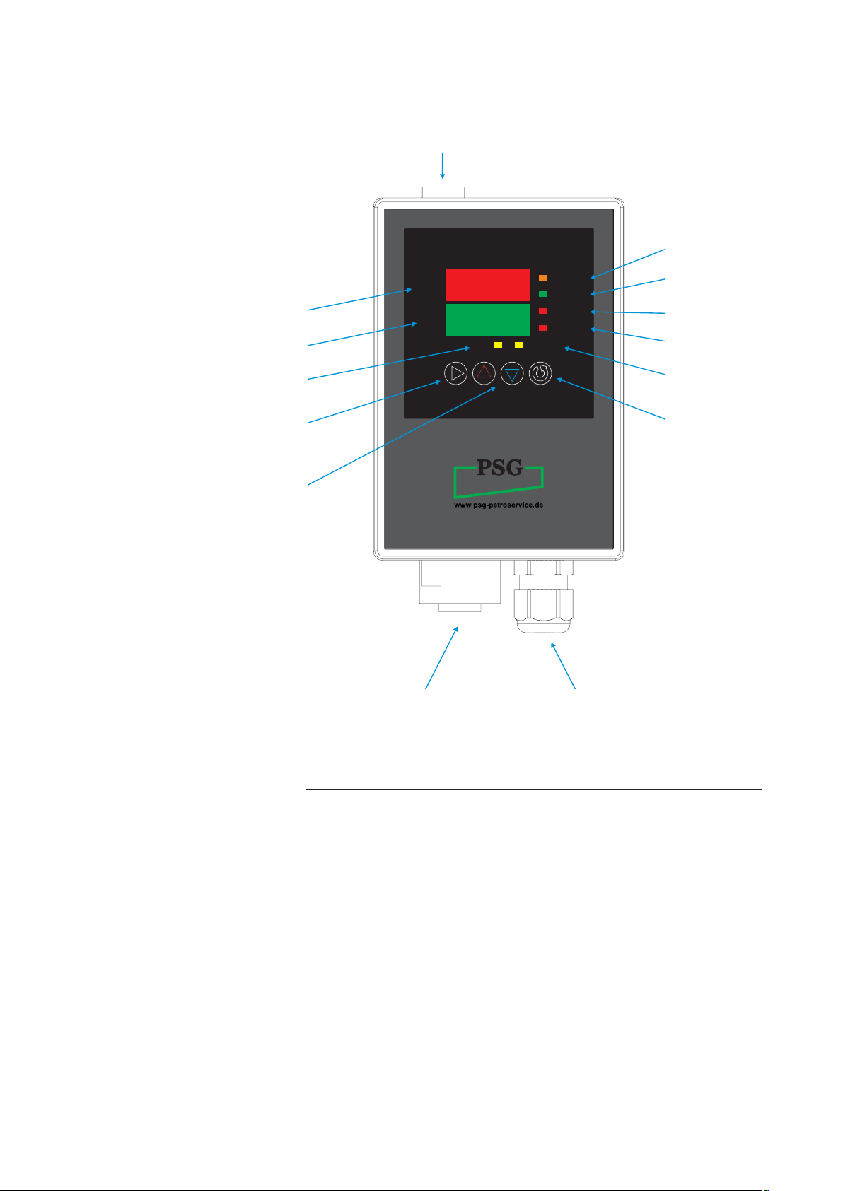
PROCESS
VALUE
SET
VALUE
COM
AUTO TUNE
ENERGIZED
IN RANGE
OUT RANGE
ALARM
DC-10
ON/OFF
Illustration
Temperatur Controller
fuse
output
process value
within limits
process value
set value
communication
shift key
ON/OFF
increasing
decreasing
process value
outside limits
alarm
auto tuningexternal
mode key
power supplyplug socket for load and
temperature sensor
BA/PSG/DC10/0.2/0513/EN
3
Page 6

2.2 Technical specifications
Technical Data
Nominal voltage: 115 or 230 V
(see type plate)
Max. load: 10 A
Frequency: 50...60 Hz
Power consumption: 6 W (w/o load)
Temperature senso
type J (-200...+1.000°C)
type K (-200...+1.370°C
(see type plate)
Control accuracy: ± 0,3% of the measuring range
Solid state relay:
Power connection: Power cable with CEE connector
IP44
Load connection: 6-pole Amphenol® plug socket
type “Ecomate” (standard)
r: Thermocouple
Zero crossing
BA/PSG/DC10/0.2/0513/EN
Housing: Aluminium light grey
Protection grade: IP 65
Dimensions: 130x90x70 mm
Weight:
Ambient temperature: 0...+50 °C
800 g
4
Page 7

2.3 Intended use
Intended Use
Unintended Use
The temperature controller is deemed to be used as intended only
if attention is paid to the following points:
• The temperature controller is designed for industrial
applications according to EN 61326.
• The temperature controller is used for the controlling of
non-inductive loads
• The temperature controller is used interior and as mobile
device (hand-held or table-top unit) or as stationary device
(wall mounted).
• The directives of the operating company must be obeyed.
• The legal regulations for the prevention of industrial accidents
must be satisfied.
Considered as an unintended use in terms of a foreseeable misuse are:
.
BA/PSG/DC10/0.2/0513/EN
• the controlling of inductive loads.
• the operation under conditions other than assumed in this ma nual
• the operation of the temperature controller by uninstructed or
unauthorized personnel.
5
Page 8

2.4 EC Declaration of Conformity
pursuant to EC low voltage directive 2006/95/EG
The manufacturer
PSG Petro Service GmbH & Co. KG
Industriestr. 8a
61449 Steinbach/Ts.
Germany
hereby declares, that the below-mentioned device
Temperature controller, type DC10
complies with the regulations of the following directives:
• EC low voltage directive 2006/95/EG
• EMC directive 2004/108/EG
Adopted standards and specifications:
• DIN EN 61010
Safety requirements for electrical equipment for measurement, control, and laboratory use
BA/PSG/DC10/0.2/0513/EN
Steinbach/TS., 02.05.2013
Place, Date Signature
Jörg Erens, Managing Director
6
Page 9

3. Essential safety instructions
Summary
Preface
In this chapter you will find the following sections:
• Safety symbols used
• Primary hazards
The following essential safety instructions are to be regarded
supplementary to already nationally applicable rules and legal
regulations for the prevention of industrial accidents. According to
this, you must always obey applicable rules and legal regulations
for the prevention of industrial accidents in addition to these essential safety instructions.
3.1 Safety symbols used
BA/PSG/DC10/0.2/0513/EN
DANGER OF
DEATH!
This symbol indicates an electrical hazard arising from exposure
to electrical voltages.
Possible lethal hazards are indicated separately by the expression
“DANGER OF DEATH!”.
7
Page 10

3.2 Primary hazards
Summary
DANGER OF
DEATH!
Here you will find information on the essential safety instructions
that allow for a safe handling of the temperature controller.
The temperature controller utilizes voltages of 230 V with correspondingly high amperages. Since amperages as of 40 mA can
be lethal, appropriate precautions are to be taken.
Preventive measures:
• Do not touch any current-conducting parts.
• Keep all coverings of the electrical installations shut.
• Immediately report damaged cables or parts to the person
responsible for the temperature controller.
• Installation work may only be carried out by qualified person nel.
BA/PSG/DC10/0.2/0513/EN
8
Page 11
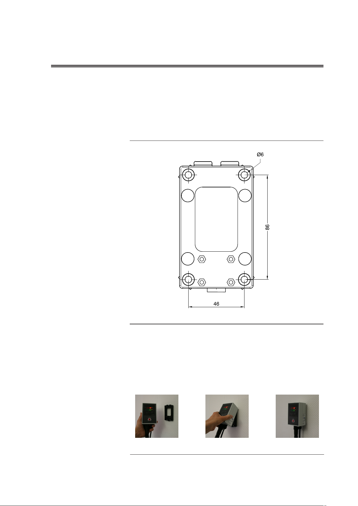
4. Wall mounting
Coupling frame
pattern of drilling
quick coupling frame
To install the tempeature controller on a wall take out the quick
coupling frame. To do so, unlock the latch by pushing it inside at
the lower face side using an appropriate tool.
Install the frame on a wall or another surface being suitable for
using the following pattern of drilling.
attaching the
temperature controller
BA/PSG/DC10/0.2/0513/EN
Once the quick coupling frame is installed attach the temperature
controller on the frame. To do so, hook the controller on the upper
connection fins being inclined backwards. Then tilt the controller
parallel to the frame until the latch is snapping into the controller
housing.
9
Page 12

5. Electrical connection
Competence
Safeguarding
The electrical connection of the temperature controller may only
be carried out by “authorized personnel”.
The manufacturer assumes no liability for installation work performed by the operator and for thereby resulting damages or
injuries.
The power supply of the temperature controller must be safeguarded by means of a residual-current circuit breaker (RCCB)
together with an overcurrent circuit breaker (OCB). Alternatively, a
combined residual current operated circuit-breaker with overcurrent protection (RCBO) can be employed.
BA/PSG/DC10/0.2/0513/EN
10
Page 13
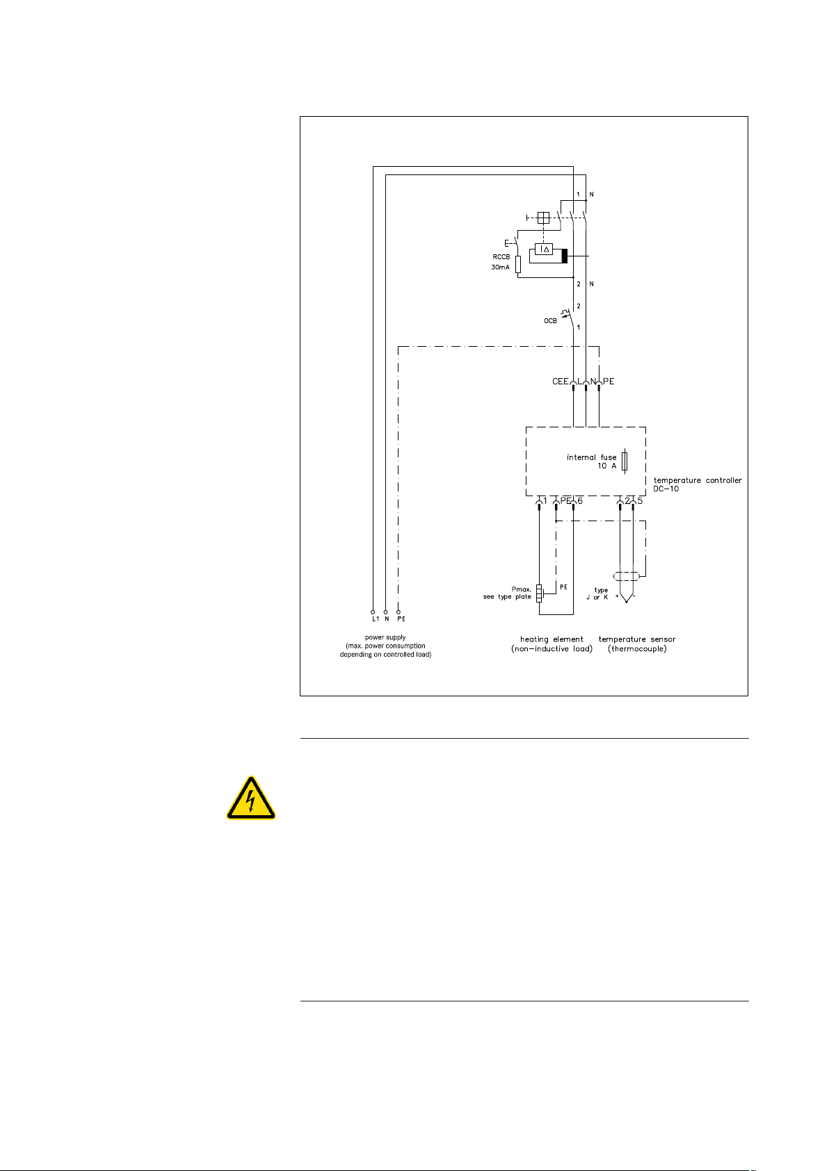
Wiring Diagram
BA/PSG/DC10/0.2/0513/EN
DANGER OF
DEATH!
The temperature controller utilizes voltages of 230 V with correspondingly high amperages. Since amperages as of 40 mA can
be lethal, appropriate precautions are to be taken.
Preventive measures:
• Do not touch any current-conducting parts.
• Immediately report damaged cables or parts to the person
responsible for the temperature controller.
• Installation work may only be carried out by qualified person nel.
11
Page 14

6. Configuration
Summary
In this chapter you will find the following sections:
• Start-up (quick guide)
• Auto tuning
• Limiter function
• Set value limits
• Menu structure and parameter values
6.1 Start-up (quick guide)
As long as the temperature controller is not factory-preset for your
application, obey the following instructions to put the controller
into operation.
power supply
Connect the controller to the power supply voltage. The controller
will display the following symbols for 3 seconds:
temperature sensor
BA/PSG/DC10/0.2/0513/EN
Press the ▲▼ keys synchronously for 3 seconds. The process
value display is showing the following symbols:
input type
The set value display is showing the sensor type. To modify the
sensor type press the ▲ or ▼ key.
For a thermocouple type K select
_ _ for °C (-200...+1.370°C) or
_ _ for °F (-320...+2.500°F)
For a thermocouple type J select
_ _ for °C (-200...+1.000°C) or
_ _ for °F (-320...+1.800°F)
12
Page 15

Now press the mode key repeatedly until you get back to the PV/
SV display mode. Then the process value is empty (- - - -) and
the set value is showing zero (0).
set value
set value (SV)
connecting
heating circuit
status output
ENERGIZED
ON / OFF
Press the mode key again. The set value display is showing the
following symbol:
Adjust your specific set value using the ▲ or ▼ keys. By using the
shift key ► the digits can also be selected directly. The active digit
is blinking.
Finally press the mode key again to go back to the display mode.
Connect the heating circuit to the controller via the plug socket.
Ensure the connector pin assignment scheme corresponds to that
of the plug (see wiring diagram, chapter 5).
The orange coloured LED “ENERGIZED” indicates the status of
the output. The heating circuit is energized if the LED is lit.
To switch
seconds. If the controller is off the process value is showing the
following symbols:
the controller on or off press the shift key ► for 3
6.2 Auto tuning
BA/PSG/DC10/0.2/0513/EN
The PID parameter of the temperature controller are factory-preset to standard values. However, you can manually modify the
control performance in order to optimze it for your application. To
do so, select the corresponding parameter values according to
section 6.5.
You can also have the optimal PID values being automatically
determinded. To do so, proceed as follows:
Press the ▲ key and the mode key synchronously.
The process value display is showing the following symbols:
13
Page 16

Auto Tune
AUTO TUNE
Press the ▲ or ▼ key until the set value display is also showing
.
Confirm the setting by pressing the mode key.
The controller is switching to the display mode and starting the
auto tuning function. While the controller is calculating the PID
values the yellow LED “AUTO TUNE” is lit. As soon as the values
are calculated the auto tuning function switches off automatically
and the LED “AUTO TUNE” is unlit.
The auto tuning procedure will take at least as long as the set
value is reached for the first time.
You can access the calculated values by selecting the corre
sponding parameters as described under chapter 6.5.
6.3 Limiter function
The temperature controller offers a limiter function which opens
the output circuit, i.e. switches off the heating system, if a set tem
ALARM
perature limit is exceeded. Then the red LED “ALARM” is lit. The
controller output circuit remains open as long as the process value
exceeds the set limit value.
To use the limiter function proceed as follows:
Press the ▲ and ▼ key synchronously for 3 seconds. The process value display is showing the following symbols:
-
-
inner event 3 type
BA/PSG/DC10/0.2/0513/EN
Now press the mode key repeatedely until the process value display is showing
.
Press the ▲ or ▼ key until the set value display is showing the
following symbols:
14
Page 17

process high alarm
.
Confirm the setting by pressing the mode key. The process value
display is showing the symbols
inner event 3 function
reverse
control output type
AND operation
control output
allocation
.
Set the digits in the set value display to
.
To do so, select the corresponding digit using the shift key
change the value using the ▲ or ▼ key. Confirm the setting by
pressing the mode key. Then press the mode key as many times
until the process value display is showing
.
Press the ▲ or ▼ key until the set value display is showing
.
Confirm the setting by pressing the mode key. Then press the
mode key as many times until the process value is showing
.
► and
B=inner event 3
C=always ON
D=always ON
BA/PSG/DC10/0.2/0513/EN
A=MV
inner event 3
main setting
Set the digits in the set value display to
.
To do so, select the corresponding digit using the shift key
change the value using the ▲ or ▼ key. Confirm the setting by
pressing the mode key.
Now press the mode key repeatedly until you get back to the
display mode. Then the process value display and the set value
display are showing the messured value and the set value repsectively.
Now you can set the limits in the “main setting mode”. To do so,
again press the mode key until the process value display is showing the following symbols:
► and
15
Page 18
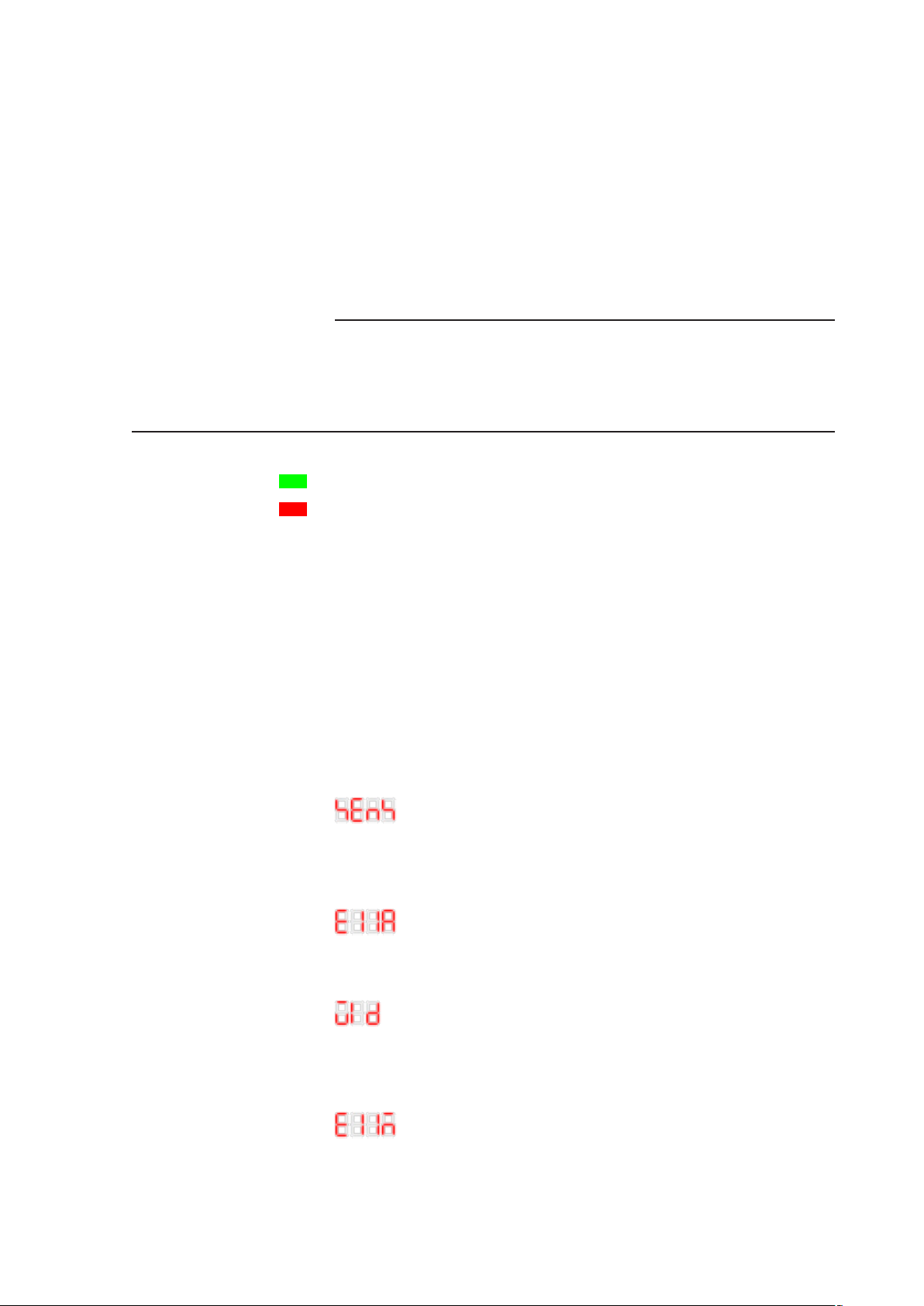
Set the required limit value using the ▲ or ▼ key. Using the shift
key ► the digits can also be selected directly. The active digit is
blinking.
Now press the mode key repeatedly until you get back to the
display mode. Then the process value display and the set value
display are showing the messured value and the set value respectively.
6.4 Set value limits
IN RANGE
OUT RANGE
inner event 1 type
The temperature controller is able to indicate a defined temperature deviation by the green LED “IN RANGE” and the red LED
“OUT RANGE”. Therefore at first the limits must be set defining
the acctepable range of the process value.
The required settings will be demonstrated assuming a tolerable
temperature deviation of ± 2K as an example: The green LED “IN
RANGE” shall be lit as long as the process value is 2K or less
lower or higher than the set value. The red LED “OUT RANGE”
shall be lit as soon as the process value is 3K or more lower or
higher than the set value.
Press the ▲▼ keys synchronously for 3 seconds. The process
value display is showing the following symbols:
.
Press the mode key repeatedely until the process value display is
showing:
.
BA/PSG/DC10/0.2/0513/EN
inner event 1 function
high/low limit
range alarm
Press the ▲ or ▼ key until the set value display is showing
.
Confirm the setting by pressing the mode key. The process value
display is showing the symbols
.
16
Page 19

Set the digits in the set value display to
no function
inner event 2 type
high/low limit alarm
inner event 3 type
no function
.
To do so, select the corresponding digit using the shift key
change the value using the ▲ or ▼ key. Confirm the setting by
pressing the mode key. Then press the mode repeatedely until the
process value display is showing
.
Press the ▲ or ▼ key until the set value display is showing
.
Confirm the setting by pressing the mode key. The process value
display is showing the symbols
.
Set the digits in the set value display to
.
► and
BA/PSG/DC10/0.2/0513/EN
inner event 1
main setting
inner event 1
sub setting
To do so, select the corresponding digit using the shift key
change the value using the ▲ or ▼ key. Confirm the setting by
pressing the mode key.
Now press the mode key repeatedely until you get back to the
display mode. Then the process value display and the set value
display are showing the messured value and the set value respectively.
To define the admissibile temperature limits go to the “main setting mode”. To do so, press the mode key until the process value
display is showing the following symbols:
Set the admissible positive temperature deviation using the ▲
or ▼ key (2 for a.m. example). Using the shift key ► the digits
can also be selected directly. The active digit is always blinking.
Confirm the setting by pressing the mode key. The process value
display is showing the symbols
.
► and
17
Page 20

Set the admissible negative temperature deviation using the ▲ or
▼ key (2 for a.m. example). Confirm the setting by pressing the
mode key.
Now press the mode key repeatedely until you get back to the
display mode. Then the process value display and the set value
display are showing the messured value and the set value respectively.
inner event 2
main setting
inner event 2
sub setting
To set the inadmissible temperature limits go to the
mode”. To do so, press the ▲ key and the mode key synchronously. The process value display is showing the following symbols:
.
Press the mode key repeatedely until the process value display is
showing:
.
Set the inadmissible positive temperature deviation using the ▲ or
▼ key (2+1=3 for a.m. example).
Confirm the setting by pressing the mode key. The process value
display is showing the symbols
.
Set the inadmissible negative temperature deviation using the ▲
or ▼ key (2+1=3 for a.m. example).
Confirm the setting by pressing the mode key.
Now press the mode key repeatedely until you get back to the
display mode. The process value display and the set value display
are then showing the messured value and the set value respectively.
“sub setting
BA/PSG/DC10/0.2/0513/EN
18
Page 21
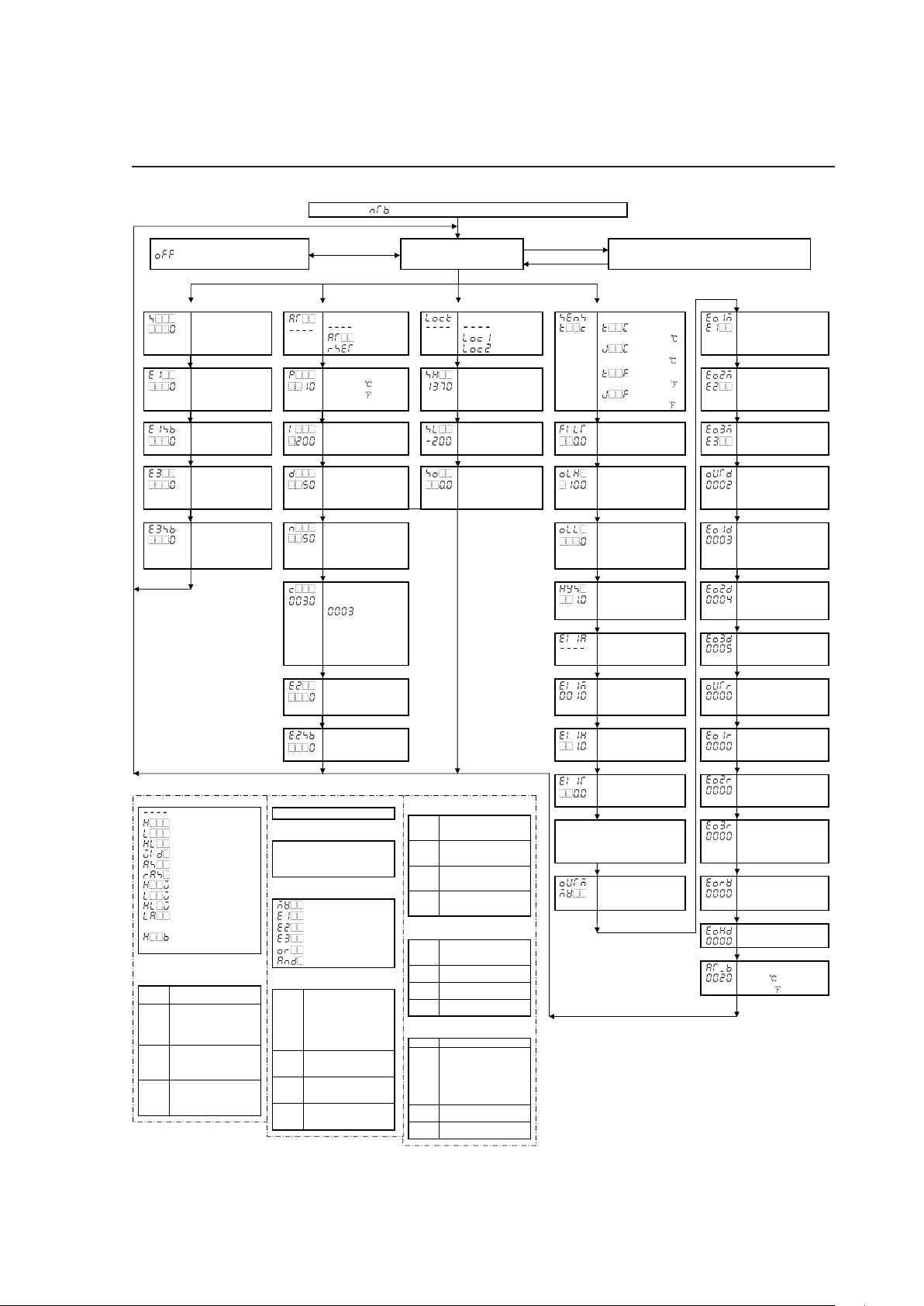
Power ON ( is indicated on the PV display f or 3 sec after power-on.)
Standby mode
is indicated on the PV display.
SHIFT Ke y (3sec)
PV/SV display mode
Mode Key (3 sec)
Mode Key
Output MV indication mode
The 1st dot from the right on the SV display
flashes in 500ms cycles during MV indication.
[Main setting mode] [Sub setting mode] [Auxiliary function setting mode 1] [Auxiliary function setting mode 2]
SV
SV low l imit to SV
high limit
AT/Auto-reset
: Cancel
: AT
: Auto-reset
Set value lock
: Cancel
: Lock 1
: Lock 2
Input type
�
K -200 to 1370
�
EVT1 output type
(Table 3-6)
Mode Key Mode Key Mode Key J -200 to 1000 Mode Key
Inner event 1
Main setting
(Table 3-1)
Proportional band
0 to 1000 or
0 to 2000
SV high limit
SV low limit to
Input range high
limit
�
K -320 to 2500
�
J -320 to 1800
EVT2 output type
(Table 3-6)
Mode Key Mode Key Mode Key Mode Key Mode Key
Inner event 1
Sub settin
g
(Table 3-1)
Integral time
0 to 1000 sec
SV low limit
Input range low limit
to SV high limit
PV filter time
constant
0.0 to 10.0 sec
EVT3 output type
(Table 3-6)
Mode Key Mode Key Mode Key Mode Key Mode Key
Inner event 3
Main setting
(Table 3-1)
Derivative time
0 to 300 sec
Sensor correction
-100.0 to 100.0
Control output high
limit
Output low limit to
105%
Control output
allocation
(Table 3-7)
Mode Key Mode Key Mode Key Mode Key Mode Key
Inner event 3
Sub setting
(Table 3-1)
ARW
0 to 100%
Control output low
limit
-5% to Output high
limit
EVT1 output
allocation
(Table 3-7)
Mode Key
Mode Key
Mode Key Mode Key
(Relay
Proportional cycle
1 to 120 sec
:Non-contact
ON/OFF hysteresis
0.1 to 100.0
EVT2 output
allocation
(Table 3-7)
contact
voltage output
Mode Key Mode Key
output)
Unavailable for DC
current output
Inner event 1 type
(Table 3-2)
EVT3 output
allocation
(Table 3-7)
Mode Key
Mode Key Mode Key
Inner event 2
Main setting
(Table 3-1)
Inner event 1
function
(Table 3-3)
Control output
allocation reverse
(Table 3-8)
Mode Key
Mode Key Mode Key
Inner event 2
Sub setting
(Table 3-1)
Inner event 1
hysteresis
(Table 3-4)
EVT1 output
allocation reverse
(Table 3-8)
Mode Key Mode Key Mode Key
Inner event 1
ON delay timer
(Table 3-5)
EVT2 output
allocation reverse
(Table 3-8)
Mode Key Mode Key
For type, function, hysteresis
and ON delay timer setting of
Inner event 2 and 3, see
(Tables 3-2, 3-3, 3-4, 3-5).
EVT3 output
allocation reverse
(Table 3-8)
Mode Key Mode Key
Control output
type
(Table 3-6)
Output Energized/
De-energized
(Table 3-9)
Mode Key Mode Key
Output H OLD
(Table 3-10)
Mode Key
AT bias
0 to 50
or
0 to 100
Mode Key
(Table 3-2) Inner e vent type
: No alarm action
: High limit alarm
: Low limit alarm
: High/Low limits alarm
: Hi/Lo limits range alarm
: Process high alarm
: Process low alarm
: High limit with standby
: Low limit with standby
: Hi/Lo limits with standby
: Loop br eak alarm
(Event 2 on ly)
: Heater burnout alarm
(Event 3 on ly)
(Table 3-3) Inner e vent function
(From right on the SV display)
1st
digit
Direct/Reverse
0: Direct 1: Reverse
2nd
digit
HOLD during standby
0: Forced OFF
1: HOLD
2: Continue
3rd
digit
Operation when input error
0: No operation
1: OR o peration
2: ANDoperation
4th
digit
Delay time unit
0: 0.1 s ec
1: 1 sec
2: 1 minute
(Table 3-8) Control output allocation
reverse (From right on the SV display)
1st
digit
Output allocation A
0: Not r eversed
1: Reversed
2nd
digit
Output allocation B
0: Not r eversed
1: Reversed
3rd
digit
Output allocation C
0: Not r eversed
1: Reversed
4th
digit
Output allocation D
0: Not r eversed
1: Reversed
(Table 3-9) Output Energized/
De-energized(From right on SV display)
1st
digit
Control output
0: Energized
1: De-energized
2nd
digit
EVT1 output
0: Energized, 1:De-energized
3rd
digit
EVT2 output
0: Energized, 1:De-energized
4th
digit
EVT3 output
0: Energized, 1:De-energized
(Table 3-10) Output HOLD
(From right on the SV display)
1st digit Ineffective
2nd
digit
EVT1 output
0: Standby mode:
Output forced OFF
1: Standby mode:
Usual operation
2: PV/SV display mode:
Output HOLD
3rd
digit
EVT2 output
The same as EVT1 output
4th
digit
EVT3 output
The same as EVT1 output
(Table 3-4) Inner e vent hysteresis
0.1 to 100.0
(Table 3-5) Inner e vent ON delay timer
0.0 to 999.9 (when delay time unit is
0.1 sec )
0 to 9999 (when delay time un it is
1 sec or 1 minute)
(Table 3-6) Control output type
: MV
: Inner event 1 result
: Inner event 2 result
: Inner event 3 result
: OR oper ation
: AND ope ration
(Table 3-7) Control output allocation
1st
digit
Output allocation A
0: Always OFF (0)
1: Always ON (1)
2: MV
3: Inner e vent 1
4: Inner e vent 2
5: Inner e vent 3
2nd
digit
Output allocation B
The same as those of
Output allocation A
3rd
digit
Output allocation C
The same as those of
Output allocation A
4th
digit
Output allocation D
The same as those of
Output allocation A
Mode Key
Increase+Mode Key Decrease+Mode Key(3sec)
Increase+Decrease Key(3sec)
6.5 Menu structure and parameter values
BA/PSG/DC10/0.2/0513/EN
19
Page 22

(Table 3-1) Inner event main and sub settings and range
High limit alarm Main setting: –(Input span) to Input span, Sub setting: Unavailable (Off when set to 0 or 0.0)
Low limit alarm Main setting: –(Input span) to Input span, Sub setting: Unavailable (Off when set to 0 or 0.0)
High/Low limits alarm Main setting: 0 to input span, Sub setting range: 0 to input span (Off when set to 0 or 0.0)
H/L limit range alarm Main setting: 0 to input span, Sub setting range: 0 to Input span (Off when set to 0 or 0.0)
Process high alarm Main setting: Input range low limit to Input range high limit, Sub setting: Unavailable
Process low alarm Main setting: Input range low limit to Input range high limit, Sub setting: Unavailable
High limit with standby Main setting: –(Input span) to Input span, Sub setting: Unavailable
Low limit with standby Main setting: –(Input span) to Input span, Sub setting: Unavailable
H/L limits with standby Main setting: 0 to input span, Sub setting: Unavailable (Off when set to 0 or 0.0)
Loop break alarm
(EVT2 only)
Main setting (Loop break alarm time): 0 to 200 minutes
Sub setting (Loop break alarm span): 0 to 150 (0.0 to 150.0)
( )
Off when either main or sub setting value is set to 0.
Heater burnout alarm
(W option) (EVT3 only)
Main setting (Heater burnout alarm): 0.0 to 20.0A, Sub setting: Unavailable
(Off when main setting value is set to 0.)
BA/PSG/DC10/0.2/0513/EN
20
 Loading...