

Page 1

QuickScan® 3000 & 3500
Handheld Bar Code Scanner
Product Reference Guide
Page 2

PSC Inc
959 Terry Street
Eugene, Oregon 97402
Telephone: (541) 683-5700
Fax: (541) 345-7140
Copyright ©2002 PSC Inc. An Unpublished Work - All rights reserved. No part of the contents of this documentation or the procedures described therein may be reproduced or transmitted in any form or by any means without
prior written permission of PSC Inc. or its wholly owned subsidiaries ("PSC"). Owners of PSC products are hereby
granted a non-exclusive, revocable license to reproduce and transmit this documentation for the purchaser's own
internal business purposes. Purchaser shall not remove or alter any proprietary notices, including copyright
notices, contained in this documentation and shall ensure that all notices appear on any reproductions of the documentation.
Should future revisions of this manual be published, you can acquire printed versions by contacting PSC Customer
Administration. Electronic versions will either be downloadable from the PSC web site (www.pscnet.com) or pro-
vided on appropriate media. If you visit our web site and would like to make comments or suggestions about this or
other PSC publications, please let us know via the “Contact PSC” page.
Disclaimer
Reasonable measures have been taken to ensure that the information included in this manual is complete and
accurate. However, PSC reserves the right to change any specification at any time without prior notice.
PSC is a registered trademark of PSC Inc. The PSC logo is a trademark of PSC. All other trademarks and trade
names referred to herein are property of their respective owners.
Page 3

Contents
About This Guide
Introduction . . . . . . . . . . . . . . . . . . . . . . . . . . . . . . . . . . . . . . . . . . . . . . . . . . . . . . . . . . . . . . . . . . . .ix
Chapter Descriptions. . . . . . . . . . . . . . . . . . . . . . . . . . . . . . . . . . . . . . . . . . . . . . . . . . . . . . . . . . . . .ix
Notational Conventions . . . . . . . . . . . . . . . . . . . . . . . . . . . . . . . . . . . . . . . . . . . . . . . . . . . . . . . . . . .xi
Related Publications . . . . . . . . . . . . . . . . . . . . . . . . . . . . . . . . . . . . . . . . . . . . . . . . . . . . . . . . . . . . .xi
Service Information . . . . . . . . . . . . . . . . . . . . . . . . . . . . . . . . . . . . . . . . . . . . . . . . . . . . . . . . . . . . . .xi
PSC Inc. Support Center. . . . . . . . . . . . . . . . . . . . . . . . . . . . . . . . . . . . . . . . . . . . . . . . . . . . . . . . . xii
Warranty . . . . . . . . . . . . . . . . . . . . . . . . . . . . . . . . . . . . . . . . . . . . . . . . . . . . . . . . . . . . . . . . . . . . . xiii
Warranty Coverage and Procedure . . . . . . . . . . . . . . . . . . . . . . . . . . . . . . . . . . . . . . . . . . . . .xiii
General. . . . . . . . . . . . . . . . . . . . . . . . . . . . . . . . . . . . . . . . . . . . . . . . . . . . . . . . . . . . . . . . . . .xiv
Chapter 1. Getting Started
Introduction . . . . . . . . . . . . . . . . . . . . . . . . . . . . . . . . . . . . . . . . . . . . . . . . . . . . . . . . . . . . . . . . . . 1-1
Unpacking Your Scanner. . . . . . . . . . . . . . . . . . . . . . . . . . . . . . . . . . . . . . . . . . . . . . . . . . . . . . . . 1-2
Setting Up the Scanner . . . . . . . . . . . . . . . . . . . . . . . . . . . . . . . . . . . . . . . . . . . . . . . . . . . . . . . . . 1-3
Installing the Interface Cable . . . . . . . . . . . . . . . . . . . . . . . . . . . . . . . . . . . . . . . . . . . . . . . . . 1-3
Connecting Power (if required). . . . . . . . . . . . . . . . . . . . . . . . . . . . . . . . . . . . . . . . . . . . . . . . 1-4
Configuring Your Scanner . . . . . . . . . . . . . . . . . . . . . . . . . . . . . . . . . . . . . . . . . . . . . . . . . . . 1-4
Connecting a Synapse Cable Interface . . . . . . . . . . . . . . . . . . . . . . . . . . . . . . . . . . . . . . . . . 1-5
Removing the Interface Cable . . . . . . . . . . . . . . . . . . . . . . . . . . . . . . . . . . . . . . . . . . . . . . . . 1-5
Chapter 2. Scanning
Introduction . . . . . . . . . . . . . . . . . . . . . . . . . . . . . . . . . . . . . . . . . . . . . . . . . . . . . . . . . . . . . . . . . . 2-1
Beeper Definitions . . . . . . . . . . . . . . . . . . . . . . . . . . . . . . . . . . . . . . . . . . . . . . . . . . . . . . . . . . . . . 2-2
LED Definitions . . . . . . . . . . . . . . . . . . . . . . . . . . . . . . . . . . . . . . . . . . . . . . . . . . . . . . . . . . . . . . . 2-4
Scanning in Hand-Held Mode . . . . . . . . . . . . . . . . . . . . . . . . . . . . . . . . . . . . . . . . . . . . . . . . . . . . 2-5
Aiming . . . . . . . . . . . . . . . . . . . . . . . . . . . . . . . . . . . . . . . . . . . . . . . . . . . . . . . . . . . . . . . . . . . . . . 2-6
Decode Zones . . . . . . . . . . . . . . . . . . . . . . . . . . . . . . . . . . . . . . . . . . . . . . . . . . . . . . . . . . . . . . . . 2-7
Scanning in Hands-Free Mode . . . . . . . . . . . . . . . . . . . . . . . . . . . . . . . . . . . . . . . . . . . . . . . . . . . 2-9
i
Page 4

QuickScan QS3000/QS3500 Product Reference Guide
Assembling the Stand . . . . . . . . . . . . . . . . . . . . . . . . . . . . . . . . . . . . . . . . . . . . . . . . . . . . . . . 2-9
Mounting the Stand (optional) . . . . . . . . . . . . . . . . . . . . . . . . . . . . . . . . . . . . . . . . . . . . . . . .2-10
Scanning in the Stand . . . . . . . . . . . . . . . . . . . . . . . . . . . . . . . . . . . . . . . . . . . . . . . . . . . . . .2-11
Chapter 3. Maintenance and Technical Sp ecifications
Introduction. . . . . . . . . . . . . . . . . . . . . . . . . . . . . . . . . . . . . . . . . . . . . . . . . . . . . . . . . . . . . . . . . . .3-1
Maintenance . . . . . . . . . . . . . . . . . . . . . . . . . . . . . . . . . . . . . . . . . . . . . . . . . . . . . . . . . . . . . . . . . .3-1
Troubleshooting . . . . . . . . . . . . . . . . . . . . . . . . . . . . . . . . . . . . . . . . . . . . . . . . . . . . . . . . . . . . . . .3-2
Technical Specifications . . . . . . . . . . . . . . . . . . . . . . . . . . . . . . . . . . . . . . . . . . . . . . . . . . . . . . . . .3-4
Scanner Signal Descriptions. . . . . . . . . . . . . . . . . . . . . . . . . . . . . . . . . . . . . . . . . . . . . . . . . . . . . . 3-6
Chapter 4. User Preferences
Introduction. . . . . . . . . . . . . . . . . . . . . . . . . . . . . . . . . . . . . . . . . . . . . . . . . . . . . . . . . . . . . . . . . . .4-1
Scanning Sequence Examples . . . . . . . . . . . . . . . . . . . . . . . . . . . . . . . . . . . . . . . . . . . . . . . . . . . .4-2
Errors While Scanning . . . . . . . . . . . . . . . . . . . . . . . . . . . . . . . . . . . . . . . . . . . . . . . . . . . . . . . . . . 4-2
User Preferences Default Parameters . . . . . . . . . . . . . . . . . . . . . . . . . . . . . . . . . . . . . . . . . . . . . . 4-3
User Preferences . . . . . . . . . . . . . . . . . . . . . . . . . . . . . . . . . . . . . . . . . . . . . . . . . . . . . . . . . . . . . . 4-4
Set Default Parameter. . . . . . . . . . . . . . . . . . . . . . . . . . . . . . . . . . . . . . . . . . . . . . . . . . . . . . . 4-4
Trigger Mode . . . . . . . . . . . . . . . . . . . . . . . . . . . . . . . . . . . . . . . . . . . . . . . . . . . . . . . . . . . . . .4-5
Beeper Tone . . . . . . . . . . . . . . . . . . . . . . . . . . . . . . . . . . . . . . . . . . . . . . . . . . . . . . . . . . . . . . 4-6
Beeper Volume . . . . . . . . . . . . . . . . . . . . . . . . . . . . . . . . . . . . . . . . . . . . . . . . . . . . . . . . . . . . 4-7
Laser On Time. . . . . . . . . . . . . . . . . . . . . . . . . . . . . . . . . . . . . . . . . . . . . . . . . . . . . . . . . . . . . 4-8
Beep After Good Decode. . . . . . . . . . . . . . . . . . . . . . . . . . . . . . . . . . . . . . . . . . . . . . . . . . . . . 4-9
Chapter 5. Keyboard Wedge Interface
Introduction. . . . . . . . . . . . . . . . . . . . . . . . . . . . . . . . . . . . . . . . . . . . . . . . . . . . . . . . . . . . . . . . . . .5-1
Connecting a Keyboard Wedge Interface. . . . . . . . . . . . . . . . . . . . . . . . . . . . . . . . . . . . . . . . . . . .5-2
Keyboard Wedge Default Parameters . . . . . . . . . . . . . . . . . . . . . . . . . . . . . . . . . . . . . . . . . . . . . .5-3
Keyboard Wedge Host Parameters . . . . . . . . . . . . . . . . . . . . . . . . . . . . . . . . . . . . . . . . . . . . . . . . 5-4
Keyboard Wedge Host Types . . . . . . . . . . . . . . . . . . . . . . . . . . . . . . . . . . . . . . . . . . . . . . . . .5-4
Keyboard Wedge Country Types (Country Codes) . . . . . . . . . . . . . . . . . . . . . . . . . . . . . . . . .5-6
Ignore Unknown Characters . . . . . . . . . . . . . . . . . . . . . . . . . . . . . . . . . . . . . . . . . . . . . . . . . . 5-8
Keystroke Delay. . . . . . . . . . . . . . . . . . . . . . . . . . . . . . . . . . . . . . . . . . . . . . . . . . . . . . . . . . . .5-9
Intra-Keystroke Delay . . . . . . . . . . . . . . . . . . . . . . . . . . . . . . . . . . . . . . . . . . . . . . . . . . . . . .5-10
Alternate Numeric Keypad Emulation . . . . . . . . . . . . . . . . . . . . . . . . . . . . . . . . . . . . . . . . . .5-10
CAPS Lock On. . . . . . . . . . . . . . . . . . . . . . . . . . . . . . . . . . . . . . . . . . . . . . . . . . . . . . . . . . . . 5-11
CAPS Lock Override . . . . . . . . . . . . . . . . . . . . . . . . . . . . . . . . . . . . . . . . . . . . . . . . . . . . . . .5-11
Keyboard Maps. . . . . . . . . . . . . . . . . . . . . . . . . . . . . . . . . . . . . . . . . . . . . . . . . . . . . . . . . . . . . . . 5-12
ASCII Character Set . . . . . . . . . . . . . . . . . . . . . . . . . . . . . . . . . . . . . . . . . . . . . . . . . . . . . . . . . . .5-15
ii
Page 5

Contents
Chapter 6. RS-232 Interface
Introduction . . . . . . . . . . . . . . . . . . . . . . . . . . . . . . . . . . . . . . . . . . . . . . . . . . . . . . . . . . . . . . . . . . 6-1
Connecting an RS-232 Interface . . . . . . . . . . . . . . . . . . . . . . . . . . . . . . . . . . . . . . . . . . . . . . . . . . 6-2
RS-232 Default Parameters. . . . . . . . . . . . . . . . . . . . . . . . . . . . . . . . . . . . . . . . . . . . . . . . . . . . . . 6-2
RS-232 Host Parameters. . . . . . . . . . . . . . . . . . . . . . . . . . . . . . . . . . . . . . . . . . . . . . . . . . . . . . . . 6-4
RS-232 Host Types . . . . . . . . . . . . . . . . . . . . . . . . . . . . . . . . . . . . . . . . . . . . . . . . . . . . . . . . 6-6
Baud Rate. . . . . . . . . . . . . . . . . . . . . . . . . . . . . . . . . . . . . . . . . . . . . . . . . . . . . . . . . . . . . . . . 6-8
Parity . . . . . . . . . . . . . . . . . . . . . . . . . . . . . . . . . . . . . . . . . . . . . . . . . . . . . . . . . . . . . . . . . . 6-10
Stop Bit Select . . . . . . . . . . . . . . . . . . . . . . . . . . . . . . . . . . . . . . . . . . . . . . . . . . . . . . . . . . . 6-11
ASCII Format . . . . . . . . . . . . . . . . . . . . . . . . . . . . . . . . . . . . . . . . . . . . . . . . . . . . . . . . . . . . 6-12
Check Receive Errors. . . . . . . . . . . . . . . . . . . . . . . . . . . . . . . . . . . . . . . . . . . . . . . . . . . . . . 6-13
Hardware Handshaking . . . . . . . . . . . . . . . . . . . . . . . . . . . . . . . . . . . . . . . . . . . . . . . . . . . . 6-14
Software Handshaking . . . . . . . . . . . . . . . . . . . . . . . . . . . . . . . . . . . . . . . . . . . . . . . . . . . . . 6-16
Host Serial Response Time-out . . . . . . . . . . . . . . . . . . . . . . . . . . . . . . . . . . . . . . . . . . . . . . 6-18
RTS Line State. . . . . . . . . . . . . . . . . . . . . . . . . . . . . . . . . . . . . . . . . . . . . . . . . . . . . . . . . . . 6-19
Beep on <BEL> . . . . . . . . . . . . . . . . . . . . . . . . . . . . . . . . . . . . . . . . . . . . . . . . . . . . . . . . . . 6-20
Intercharacter Delay. . . . . . . . . . . . . . . . . . . . . . . . . . . . . . . . . . . . . . . . . . . . . . . . . . . . . . . 6-21
Prefix / Suffix Values . . . . . . . . . . . . . . . . . . . . . . . . . . . . . . . . . . . . . . . . . . . . . . . . . . . . . . . . . . 6-22
Chapter 7. USB Interface
Introduction . . . . . . . . . . . . . . . . . . . . . . . . . . . . . . . . . . . . . . . . . . . . . . . . . . . . . . . . . . . . . . . . . . 7-1
Connecting a USB Interface . . . . . . . . . . . . . . . . . . . . . . . . . . . . . . . . . . . . . . . . . . . . . . . . . . . . . 7-2
USB Default Parameters . . . . . . . . . . . . . . . . . . . . . . . . . . . . . . . . . . . . . . . . . . . . . . . . . . . . . . . . 7-4
USB Host Parameters . . . . . . . . . . . . . . . . . . . . . . . . . . . . . . . . . . . . . . . . . . . . . . . . . . . . . . . . . . 7-5
USB Device Type. . . . . . . . . . . . . . . . . . . . . . . . . . . . . . . . . . . . . . . . . . . . . . . . . . . . . . . . . . 7-5
USB Country Keyboard Types (Country Codes) . . . . . . . . . . . . . . . . . . . . . . . . . . . . . . . . . . 7-6
USB Keystroke Delay. . . . . . . . . . . . . . . . . . . . . . . . . . . . . . . . . . . . . . . . . . . . . . . . . . . . . . . 7-9
USB CAPS Lock Override . . . . . . . . . . . . . . . . . . . . . . . . . . . . . . . . . . . . . . . . . . . . . . . . . . 7-10
USB Ignore Unknown Characters. . . . . . . . . . . . . . . . . . . . . . . . . . . . . . . . . . . . . . . . . . . . . 7-11
ASCII Character Set . . . . . . . . . . . . . . . . . . . . . . . . . . . . . . . . . . . . . . . . . . . . . . . . . . . . . . . . . . 7-12
Chapter 8. IBM 468X/469X In te rfa ce
Introduction . . . . . . . . . . . . . . . . . . . . . . . . . . . . . . . . . . . . . . . . . . . . . . . . . . . . . . . . . . . . . . . . . . 8-1
Connecting to an IBM 468X/469X Host. . . . . . . . . . . . . . . . . . . . . . . . . . . . . . . . . . . . . . . . . . . . . 8-2
IBM Default Parameters. . . . . . . . . . . . . . . . . . . . . . . . . . . . . . . . . . . . . . . . . . . . . . . . . . . . . . . . . 8-3
IBM 468X/469X Host Parameters . . . . . . . . . . . . . . . . . . . . . . . . . . . . . . . . . . . . . . . . . . . . . . . . . 8-4
Port Address. . . . . . . . . . . . . . . . . . . . . . . . . . . . . . . . . . . . . . . . . . . . . . . . . . . . . . . . . . . . . . 8-4
Convert Unknown Bar Code to Code 39 . . . . . . . . . . . . . . . . . . . . . . . . . . . . . . . . . . . . . . . . 8-5
iii
Page 6

QuickScan QS3000/QS3500 Product Reference Guide
Chapter 9. Wand Emulation Interface
Introduction. . . . . . . . . . . . . . . . . . . . . . . . . . . . . . . . . . . . . . . . . . . . . . . . . . . . . . . . . . . . . . . . . . .9-1
Connecting Using Wand Emulation . . . . . . . . . . . . . . . . . . . . . . . . . . . . . . . . . . . . . . . . . . . . . . . . 9-2
Wand Emulation Default Parameters . . . . . . . . . . . . . . . . . . . . . . . . . . . . . . . . . . . . . . . . . . . . . . .9-3
Wand Emulation Host Parameters . . . . . . . . . . . . . . . . . . . . . . . . . . . . . . . . . . . . . . . . . . . . . . . . .9-4
Wand Emulation Host Types . . . . . . . . . . . . . . . . . . . . . . . . . . . . . . . . . . . . . . . . . . . . . . . . . .9-4
Leading Margin (Quiet Zone). . . . . . . . . . . . . . . . . . . . . . . . . . . . . . . . . . . . . . . . . . . . . . . . . . 9-5
Polarity. . . . . . . . . . . . . . . . . . . . . . . . . . . . . . . . . . . . . . . . . . . . . . . . . . . . . . . . . . . . . . . . . . .9-6
Ignore Unknown Characters . . . . . . . . . . . . . . . . . . . . . . . . . . . . . . . . . . . . . . . . . . . . . . . . . . 9-7
Convert All Bar Codes to Code 39. . . . . . . . . . . . . . . . . . . . . . . . . . . . . . . . . . . . . . . . . . . . . .9-8
Code 39 Full ASCII Conversion. . . . . . . . . . . . . . . . . . . . . . . . . . . . . . . . . . . . . . . . . . . . . . . .9-8
Chapter 10. Configurator Express
Introduction. . . . . . . . . . . . . . . . . . . . . . . . . . . . . . . . . . . . . . . . . . . . . . . . . . . . . . . . . . . . . . . . . .10-1
Communication With the Configurator Express PC Based Configuration Tool. . . . . . . . . . . . . . .10-1
Configurator Express Parameter. . . . . . . . . . . . . . . . . . . . . . . . . . . . . . . . . . . . . . . . . . . . . . . . . .10-2
TM
Chapter 11. Symbologies
Introduction. . . . . . . . . . . . . . . . . . . . . . . . . . . . . . . . . . . . . . . . . . . . . . . . . . . . . . . . . . . . . . . . . .11-1
Scanning Sequence Examples . . . . . . . . . . . . . . . . . . . . . . . . . . . . . . . . . . . . . . . . . . . . . . . . . . .11-2
Errors While Scanning . . . . . . . . . . . . . . . . . . . . . . . . . . . . . . . . . . . . . . . . . . . . . . . . . . . . . . . . . 11-2
Symbology Default Parameters . . . . . . . . . . . . . . . . . . . . . . . . . . . . . . . . . . . . . . . . . . . . . . . . . .11-3
UPC/EAN . . . . . . . . . . . . . . . . . . . . . . . . . . . . . . . . . . . . . . . . . . . . . . . . . . . . . . . . . . . . . . . . . . .11-7
Enable/Disable UPC-A/UPC-E . . . . . . . . . . . . . . . . . . . . . . . . . . . . . . . . . . . . . . . . . . . . . . .11-7
Enable/Disable UPC-E1. . . . . . . . . . . . . . . . . . . . . . . . . . . . . . . . . . . . . . . . . . . . . . . . . . . . .11-8
Enable/Disable EAN-13/EAN-8 . . . . . . . . . . . . . . . . . . . . . . . . . . . . . . . . . . . . . . . . . . . . . . .11-9
Enable/Disable Bookland EAN . . . . . . . . . . . . . . . . . . . . . . . . . . . . . . . . . . . . . . . . . . . . . .11-10
Decode UPC/EAN Supplementals. . . . . . . . . . . . . . . . . . . . . . . . . . . . . . . . . . . . . . . . . . . .11-11
UPC/EAN Supplemental Redundancy. . . . . . . . . . . . . . . . . . . . . . . . . . . . . . . . . . . . . . . . .11-13
Transmit UPC-A/UPC-E/UPC-E1 Check Digit. . . . . . . . . . . . . . . . . . . . . . . . . . . . . . . . . . . 11-14
UPC-A Preamble. . . . . . . . . . . . . . . . . . . . . . . . . . . . . . . . . . . . . . . . . . . . . . . . . . . . . . . . . 11-16
UPC-E Preamble. . . . . . . . . . . . . . . . . . . . . . . . . . . . . . . . . . . . . . . . . . . . . . . . . . . . . . . . . 11-17
UPC-E1 Preamble. . . . . . . . . . . . . . . . . . . . . . . . . . . . . . . . . . . . . . . . . . . . . . . . . . . . . . . .11-18
Convert UPC-E to UPC-A . . . . . . . . . . . . . . . . . . . . . . . . . . . . . . . . . . . . . . . . . . . . . . . . . . 11-19
Convert UPC-E1 to UPC-A . . . . . . . . . . . . . . . . . . . . . . . . . . . . . . . . . . . . . . . . . . . . . . . . .11-20
EAN Zero Extend. . . . . . . . . . . . . . . . . . . . . . . . . . . . . . . . . . . . . . . . . . . . . . . . . . . . . . . . .11-21
UPC/EAN Security Level. . . . . . . . . . . . . . . . . . . . . . . . . . . . . . . . . . . . . . . . . . . . . . . . . . . 11-22
UCC Coupon Extended Code . . . . . . . . . . . . . . . . . . . . . . . . . . . . . . . . . . . . . . . . . . . . . . .11-24
Code 128 . . . . . . . . . . . . . . . . . . . . . . . . . . . . . . . . . . . . . . . . . . . . . . . . . . . . . . . . . . . . . . . . . .11-25
Enable/Disable Code 128 . . . . . . . . . . . . . . . . . . . . . . . . . . . . . . . . . . . . . . . . . . . . . . . . . . 11-25
Enable/Disable UCC/EAN-128 . . . . . . . . . . . . . . . . . . . . . . . . . . . . . . . . . . . . . . . . . . . . . .11-26
iv
Page 7

Contents
Enable/Disable ISBT 128. . . . . . . . . . . . . . . . . . . . . . . . . . . . . . . . . . . . . . . . . . . . . . . . . . 11-27
Code 39. . . . . . . . . . . . . . . . . . . . . . . . . . . . . . . . . . . . . . . . . . . . . . . . . . . . . . . . . . . . . . . . . . . 11-28
Enable/Disable Code 39. . . . . . . . . . . . . . . . . . . . . . . . . . . . . . . . . . . . . . . . . . . . . . . . . . . 11-28
Enable/Disable Trioptic Code 39 . . . . . . . . . . . . . . . . . . . . . . . . . . . . . . . . . . . . . . . . . . . . 11-29
Convert Code 39 to Code 32 (Italian Pharma Code) . . . . . . . . . . . . . . . . . . . . . . . . . . . . . 11-30
Code 32 Prefix . . . . . . . . . . . . . . . . . . . . . . . . . . . . . . . . . . . . . . . . . . . . . . . . . . . . . . . . . . 11-31
Set Lengths for Code 39. . . . . . . . . . . . . . . . . . . . . . . . . . . . . . . . . . . . . . . . . . . . . . . . . . . 11-32
Code 39 Check Digit Verification . . . . . . . . . . . . . . . . . . . . . . . . . . . . . . . . . . . . . . . . . . . . 11-34
Transmit Code 39 Check Digit . . . . . . . . . . . . . . . . . . . . . . . . . . . . . . . . . . . . . . . . . . . . . . 11-35
Enable/Disable Code 39 Full ASCII . . . . . . . . . . . . . . . . . . . . . . . . . . . . . . . . . . . . . . . . . . 11-36
Code 39 Buffering (Scan & Store) . . . . . . . . . . . . . . . . . . . . . . . . . . . . . . . . . . . . . . . . . . . 11-39
Code 93. . . . . . . . . . . . . . . . . . . . . . . . . . . . . . . . . . . . . . . . . . . . . . . . . . . . . . . . . . . . . . . . . . . 11-43
Enable/Disable Code 93. . . . . . . . . . . . . . . . . . . . . . . . . . . . . . . . . . . . . . . . . . . . . . . . . . . 11-43
Set Lengths for Code 93. . . . . . . . . . . . . . . . . . . . . . . . . . . . . . . . . . . . . . . . . . . . . . . . . . . 11-44
Code 11. . . . . . . . . . . . . . . . . . . . . . . . . . . . . . . . . . . . . . . . . . . . . . . . . . . . . . . . . . . . . . . . . . . 11-46
Enable/Disable Code 11. . . . . . . . . . . . . . . . . . . . . . . . . . . . . . . . . . . . . . . . . . . . . . . . . . . 11-46
Set Lengths for Code 11. . . . . . . . . . . . . . . . . . . . . . . . . . . . . . . . . . . . . . . . . . . . . . . . . . . 11-47
Code 11 Check Digit Verification . . . . . . . . . . . . . . . . . . . . . . . . . . . . . . . . . . . . . . . . . . . . 11-49
Transmit Code 11 Check Digits . . . . . . . . . . . . . . . . . . . . . . . . . . . . . . . . . . . . . . . . . . . . . 11-50
Interleaved 2 of 5 (ITF) . . . . . . . . . . . . . . . . . . . . . . . . . . . . . . . . . . . . . . . . . . . . . . . . . . . . . . . 11-51
Enable/Disable Interleaved 2 of 5. . . . . . . . . . . . . . . . . . . . . . . . . . . . . . . . . . . . . . . . . . . . 11-51
Set Lengths for Interleaved 2 of 5 . . . . . . . . . . . . . . . . . . . . . . . . . . . . . . . . . . . . . . . . . . . 11-52
I 2 of 5 Check Digit Verification. . . . . . . . . . . . . . . . . . . . . . . . . . . . . . . . . . . . . . . . . . . . . . 11-54
Transmit I 2 of 5 Check Digit . . . . . . . . . . . . . . . . . . . . . . . . . . . . . . . . . . . . . . . . . . . . . . . 11-55
Convert I 2 of 5 to EAN-13. . . . . . . . . . . . . . . . . . . . . . . . . . . . . . . . . . . . . . . . . . . . . . . . . 11-56
Discrete 2 of 5 (DTF). . . . . . . . . . . . . . . . . . . . . . . . . . . . . . . . . . . . . . . . . . . . . . . . . . . . . . . . . 11-57
Enable/Disable Discrete 2 of 5 . . . . . . . . . . . . . . . . . . . . . . . . . . . . . . . . . . . . . . . . . . . . . . 11-57
Set Lengths for Discrete 2 of 5. . . . . . . . . . . . . . . . . . . . . . . . . . . . . . . . . . . . . . . . . . . . . . 11-58
Codabar (NW - 7). . . . . . . . . . . . . . . . . . . . . . . . . . . . . . . . . . . . . . . . . . . . . . . . . . . . . . . . . . . . 11-60
Enable/Disable Codabar. . . . . . . . . . . . . . . . . . . . . . . . . . . . . . . . . . . . . . . . . . . . . . . . . . . 11-60
Set Lengths for Codabar . . . . . . . . . . . . . . . . . . . . . . . . . . . . . . . . . . . . . . . . . . . . . . . . . . 11-61
CLSI Editing . . . . . . . . . . . . . . . . . . . . . . . . . . . . . . . . . . . . . . . . . . . . . . . . . . . . . . . . . . . . 11-63
NOTIS Editing. . . . . . . . . . . . . . . . . . . . . . . . . . . . . . . . . . . . . . . . . . . . . . . . . . . . . . . . . . . 11-64
MSI . . . . . . . . . . . . . . . . . . . . . . . . . . . . . . . . . . . . . . . . . . . . . . . . . . . . . . . . . . . . . . . . . . . . . . 11-65
Enable/Disable MSI . . . . . . . . . . . . . . . . . . . . . . . . . . . . . . . . . . . . . . . . . . . . . . . . . . . . . . 11-65
Set Lengths for MSI . . . . . . . . . . . . . . . . . . . . . . . . . . . . . . . . . . . . . . . . . . . . . . . . . . . . . . 11-66
MSI Check Digits . . . . . . . . . . . . . . . . . . . . . . . . . . . . . . . . . . . . . . . . . . . . . . . . . . . . . . . . 11-68
Transmit MSI Check Digit(s). . . . . . . . . . . . . . . . . . . . . . . . . . . . . . . . . . . . . . . . . . . . . . . . 11-69
MSI Check Digit Algorithm . . . . . . . . . . . . . . . . . . . . . . . . . . . . . . . . . . . . . . . . . . . . . . . . . 11-70
RSS (Reduced Space Symbology) . . . . . . . . . . . . . . . . . . . . . . . . . . . . . . . . . . . . . . . . . . . . . . 11-71
RSS 14. . . . . . . . . . . . . . . . . . . . . . . . . . . . . . . . . . . . . . . . . . . . . . . . . . . . . . . . . . . . . . . . 11-71
RSS Limited . . . . . . . . . . . . . . . . . . . . . . . . . . . . . . . . . . . . . . . . . . . . . . . . . . . . . . . . . . . . 11-72
RSS Expanded. . . . . . . . . . . . . . . . . . . . . . . . . . . . . . . . . . . . . . . . . . . . . . . . . . . . . . . . . . 11-72
Symbology - Specific Security Levels . . . . . . . . . . . . . . . . . . . . . . . . . . . . . . . . . . . . . . . . . . . . 11-73
v
Page 8

QuickScan QS3000/QS3500 Product Reference Guide
Linear Code Type Security Level. . . . . . . . . . . . . . . . . . . . . . . . . . . . . . . . . . . . . . . . . . . . .11-73
Bi-directional Redundancy. . . . . . . . . . . . . . . . . . . . . . . . . . . . . . . . . . . . . . . . . . . . . . . . . .11-76
Chapter 12. Miscellaneous Scanner Options
Introduction. . . . . . . . . . . . . . . . . . . . . . . . . . . . . . . . . . . . . . . . . . . . . . . . . . . . . . . . . . . . . . . . . .12-1
Scanning Sequence Examples . . . . . . . . . . . . . . . . . . . . . . . . . . . . . . . . . . . . . . . . . . . . . . . . . . .12-2
Errors While Scanning . . . . . . . . . . . . . . . . . . . . . . . . . . . . . . . . . . . . . . . . . . . . . . . . . . . . . . . . . 12-2
Miscellaneous Default Parameters . . . . . . . . . . . . . . . . . . . . . . . . . . . . . . . . . . . . . . . . . . . . . . . . 12-3
Miscellaneous Scanner Parameters . . . . . . . . . . . . . . . . . . . . . . . . . . . . . . . . . . . . . . . . . . . . . . .12-4
Transmit Code ID Character . . . . . . . . . . . . . . . . . . . . . . . . . . . . . . . . . . . . . . . . . . . . . . . . .12-4
Prefix/Suffix Values . . . . . . . . . . . . . . . . . . . . . . . . . . . . . . . . . . . . . . . . . . . . . . . . . . . . . . . .12-5
Scan Data Options. . . . . . . . . . . . . . . . . . . . . . . . . . . . . . . . . . . . . . . . . . . . . . . . . . . . . . . . .12-6
Transmit “No Read” Message . . . . . . . . . . . . . . . . . . . . . . . . . . . . . . . . . . . . . . . . . . . . . . . .12-9
Cancel . . . . . . . . . . . . . . . . . . . . . . . . . . . . . . . . . . . . . . . . . . . . . . . . . . . . . . . . . . . . . . . . . 12-10
Chapter 13. Advanced Data Formatting
Introduction. . . . . . . . . . . . . . . . . . . . . . . . . . . . . . . . . . . . . . . . . . . . . . . . . . . . . . . . . . . . . . . . . .13-1
Rules: Criteria Linked to Actions. . . . . . . . . . . . . . . . . . . . . . . . . . . . . . . . . . . . . . . . . . . . . . . . . . 13-1
Using ADF Bar Codes. . . . . . . . . . . . . . . . . . . . . . . . . . . . . . . . . . . . . . . . . . . . . . . . . . . . . . . . . . 1 3-2
ADF Bar Code Menu Example . . . . . . . . . . . . . . . . . . . . . . . . . . . . . . . . . . . . . . . . . . . . . . . . . . . 13-2
Rule 1: The Code 128 Scanning Rule . . . . . . . . . . . . . . . . . . . . . . . . . . . . . . . . . . . . . . . . . .13-3
Rule 2: The UPC Scanning Rule. . . . . . . . . . . . . . . . . . . . . . . . . . . . . . . . . . . . . . . . . . . . . .13-4
Alternate Rule Sets . . . . . . . . . . . . . . . . . . . . . . . . . . . . . . . . . . . . . . . . . . . . . . . . . . . . . . . .13-4
Rules Hierarchy (in Bar Codes) . . . . . . . . . . . . . . . . . . . . . . . . . . . . . . . . . . . . . . . . . . . . . . . 13-6
Default Rules. . . . . . . . . . . . . . . . . . . . . . . . . . . . . . . . . . . . . . . . . . . . . . . . . . . . . . . . . . . . . 1 3-7
Special Commands. . . . . . . . . . . . . . . . . . . . . . . . . . . . . . . . . . . . . . . . . . . . . . . . . . . . . . . . . . . .13-8
Pause Duration . . . . . . . . . . . . . . . . . . . . . . . . . . . . . . . . . . . . . . . . . . . . . . . . . . . . . . . . . . .13-8
Begin New Rule. . . . . . . . . . . . . . . . . . . . . . . . . . . . . . . . . . . . . . . . . . . . . . . . . . . . . . . . . . .13-8
Save Rule . . . . . . . . . . . . . . . . . . . . . . . . . . . . . . . . . . . . . . . . . . . . . . . . . . . . . . . . . . . . . . . 13-9
Erase . . . . . . . . . . . . . . . . . . . . . . . . . . . . . . . . . . . . . . . . . . . . . . . . . . . . . . . . . . . . . . . . . . .13-9
Quit Entering Rules . . . . . . . . . . . . . . . . . . . . . . . . . . . . . . . . . . . . . . . . . . . . . . . . . . . . . . . 13-10
Disable Rule Set . . . . . . . . . . . . . . . . . . . . . . . . . . . . . . . . . . . . . . . . . . . . . . . . . . . . . . . . . 13-11
Criteria. . . . . . . . . . . . . . . . . . . . . . . . . . . . . . . . . . . . . . . . . . . . . . . . . . . . . . . . . . . . . . . . . . . . .13-12
Code Types . . . . . . . . . . . . . . . . . . . . . . . . . . . . . . . . . . . . . . . . . . . . . . . . . . . . . . . . . . . . .13-12
Code Lengths . . . . . . . . . . . . . . . . . . . . . . . . . . . . . . . . . . . . . . . . . . . . . . . . . . . . . . . . . . .13-15
Message Containing A Specific Data String . . . . . . . . . . . . . . . . . . . . . . . . . . . . . . . . . . . . 13-20
Actions . . . . . . . . . . . . . . . . . . . . . . . . . . . . . . . . . . . . . . . . . . . . . . . . . . . . . . . . . . . . . . . . . . . . 13-24
Send Data . . . . . . . . . . . . . . . . . . . . . . . . . . . . . . . . . . . . . . . . . . . . . . . . . . . . . . . . . . . . . .13-24
Setup Field(s) . . . . . . . . . . . . . . . . . . . . . . . . . . . . . . . . . . . . . . . . . . . . . . . . . . . . . . . . . . .13-28
Modify Data . . . . . . . . . . . . . . . . . . . . . . . . . . . . . . . . . . . . . . . . . . . . . . . . . . . . . . . . . . . . . 13-35
Pad Data with Spaces . . . . . . . . . . . . . . . . . . . . . . . . . . . . . . . . . . . . . . . . . . . . . . . . . . . . .13-37
Pad Data with Zeros . . . . . . . . . . . . . . . . . . . . . . . . . . . . . . . . . . . . . . . . . . . . . . . . . . . . . . 13-41
vi
Page 9

Contents
Beeps . . . . . . . . . . . . . . . . . . . . . . . . . . . . . . . . . . . . . . . . . . . . . . . . . . . . . . . . . . . . . . . . . 13-45
Send Keystroke (Control Characters and Keyboard Characters). . . . . . . . . . . . . . . . . . . . 13-46
Turn On/Off Rule Sets . . . . . . . . . . . . . . . . . . . . . . . . . . . . . . . . . . . . . . . . . . . . . . . . . . . . 13-79
Alphanumeric Keyboard. . . . . . . . . . . . . . . . . . . . . . . . . . . . . . . . . . . . . . . . . . . . . . . . . . . . . . . 13-80
Appendix A. Standard Default Parameters
Appendix B. Programming Reference
Label Identifiers . . . . . . . . . . . . . . . . . . . . . . . . . . . . . . . . . . . . . . . . . . . . . . . . . . . . . . . . . . . . . . . B-1
AIM Code Identifiers . . . . . . . . . . . . . . . . . . . . . . . . . . . . . . . . . . . . . . . . . . . . . . . . . . . . . . . . . . . B-2
Appendix C. Sample Bar Codes
Code 39. . . . . . . . . . . . . . . . . . . . . . . . . . . . . . . . . . . . . . . . . . . . . . . . . . . . . . . . . . . . . . . . . . . . . C-1
UPC/EAN. . . . . . . . . . . . . . . . . . . . . . . . . . . . . . . . . . . . . . . . . . . . . . . . . . . . . . . . . . . . . . . . . . . . C-1
UPC-A, 100%. . . . . . . . . . . . . . . . . . . . . . . . . . . . . . . . . . . . . . . . . . . . . . . . . . . . . . . . . . . . . C-1
EAN-13, 100% . . . . . . . . . . . . . . . . . . . . . . . . . . . . . . . . . . . . . . . . . . . . . . . . . . . . . . . . . . . . C-2
Code 128. . . . . . . . . . . . . . . . . . . . . . . . . . . . . . . . . . . . . . . . . . . . . . . . . . . . . . . . . . . . . . . . . . . . C-2
Interleaved 2 of 5. . . . . . . . . . . . . . . . . . . . . . . . . . . . . . . . . . . . . . . . . . . . . . . . . . . . . . . . . . . . . . C-2
RSS 14 . . . . . . . . . . . . . . . . . . . . . . . . . . . . . . . . . . . . . . . . . . . . . . . . . . . . . . . . . . . . . . . . . . . . . C-3
Appendix D. Numeric Bar Codes
0, 1. . . . . . . . . . . . . . . . . . . . . . . . . . . . . . . . . . . . . . . . . . . . . . . . . . . . . . . . . . . . . . . . . . . . . . . . . D-1
2, 3, 4. . . . . . . . . . . . . . . . . . . . . . . . . . . . . . . . . . . . . . . . . . . . . . . . . . . . . . . . . . . . . . . . . . . . . . . D-2
5, 6, 7. . . . . . . . . . . . . . . . . . . . . . . . . . . . . . . . . . . . . . . . . . . . . . . . . . . . . . . . . . . . . . . . . . . . . . . D-3
8, 9. . . . . . . . . . . . . . . . . . . . . . . . . . . . . . . . . . . . . . . . . . . . . . . . . . . . . . . . . . . . . . . . . . . . . . . . . D-4
Cancel . . . . . . . . . . . . . . . . . . . . . . . . . . . . . . . . . . . . . . . . . . . . . . . . . . . . . . . . . . . . . . . . . . . . . . D-5
Glossary
Index
vii
Page 10

QuickScan QS3000/QS3500 Product Reference Guide
viii
Page 11

About This Guide
Introduction
The QuickScan QS3000/QS3500 Product Reference Guide provides gen er al ins truc ti ons
for setting up, operating, maintaining and troubleshooting the QS3000 and QS3500
scanners.
Chapter 4, User Preferences through Appendix D, Numeric Bar Codes apply only to the
decoded QS3x00 scanners. The undecoded QS 3500 scanner has no configurable options
and is controlled by the external interface controller.
Chapter Descriptions
• Chapter 1, Getti ng Started provides a product overview and unpacking
instructions.
• Chapter 2, Scanning describes parts of the scanner, beeper and LED definitions,
how to use the scanner in hand-held and hands-free modes, and decode zones.
• Chapter 3, Maintenance and Technical Specifications provides information on how
to care for your scanner, troubleshooting, and technical specifications.
• Chapter 4, User Preferences provides the programming bar codes necessary for
selecting user preference features for your scanner.
• Chapter 5, Keyboard Wedge Interface covers information for setting up your
scanner for Keyboard Wedge operation.
• Chapter 6, RS-232 Interface covers information for setting up your scanner for RS232 operation.
• Chapter 7, USB Interface covers information for setting up your scanner for USB
operation.
ix
Page 12

QuickScan QS3000/QS3500 Product Reference Guide
• Chapter 8, IBM 468X/469X Interface covers all information for setting up your
scanner with IBM 468X/469X POS systems.
• Chapter 9, Wand Emulation Interface covers all information for setting up your
scanner for Wand Emulation operation.
• Chapter 10, Confi gur ato r Expres s
TM
(PC based scanner configuration tool)
provides the bar code you must scan to communicate with the Configurator
Express program.
• Chapter 11, Symbologies describes all symbology features and provides the
programming bar codes necessary for selecting these features for your scanner.
• Chapter 12, Miscellaneous Scanner Options includes commonly used bar codes to
customize how your data is transmitted to your host device.
• Chapter 13, Advanced Data Formatting (ADF) describes how to customize
scanned data before transmitting to the host.
• Appendix A, Standard Default Parameters provides a table of all host device and
miscellaneous scann er defaul ts.
• Appendix B, Programming Reference provides a table of AIM code identifiers,
ASCII character conversions, and keyboard maps.
• Appendix C, Sample Bar Codes includes sample bar codes.
• Appendix D, Numeric Bar Codes includes the numeric bar codes to scan for
parameters requiring specific numeric values.
x
Page 13

About This Guide
Notational Conventions
The following conventions are used in this document:
• Bullets (•) indicate:
• action items
• lists of alternatives
• lists of required steps that are not necessarily sequential
• Sequential lists (e.g., those that describe step-by-step procedures) appear as
numbered lists.
• Throughout the programming bar code menus, asterisks (*) are used to denote
default parameter settings.
* Indicates Default
*Baud Rate 9600
Feature/Option
Related Publications
The QuickScan QS3000/QS3500 Quick Reference Guide, p/n R44-2253, provides general
information to help the user get started with the scanner. It includes basic set-up and
operation instructions.
For the latest versions of the Quick Reference Guide and Product Reference Guide go to:
http://www.pscnet.com.
Service Information
If you have a problem with your equipment, contact the PSC Inc. Support Center for your
region. See page xii for contact information. Before calling, have the model number, serial
number, and several of your bar code symbols at hand.
Call the Support Center from a phone near the scanning equipment so that the service
person can try to talk you through your problem. If the equipment is found to be working
properly and the problem is reading bar codes, the Support Center will request samples of
your bar codes for analysis at our plant.
xi
Page 14

QuickScan QS3000/QS3500 Product Reference Guide
If your problem cannot be solved over the phone, you may need to return your equipment
for servicing. If that is necessary, you will be given specific directions.
Note:PSC Inc. is not responsible for any damages incurred during
shipment if the approved shipping container is not used. Shipping
the units improperly can possibly void the warranty. If the original
shipping container was not kept, contact PSC Inc. to have another
sent to you.
PSC Inc. Support Center
Before you use the unit, it must be configured to operate in your facility’s network and run
your applications.
If you have a problem running your unit or using your equipment, contact your facility’s
Technical or Systems Support. If there is a problem with the equipment, they will contact
the PSC Inc. Support Center:
North America
Telephone: [541] 683-5700
Fax: [541] 686-1702
Asia Pacific
Telephone: [852]-2-584-6210
Fax: [852]-2-521-0291
Australia
Telephone: [61] 0 (2) 9878 8999
Fax: [61] 0 (2) 9878 8688
France
Telephone: [33].01.64.86.71.00
Fax: [33].01.64 46.72.44
Germany
Telephone: 49 (0) 61 51/93 58-0
Fax: 49 (0) 61 51/93 58 58
Italy
Telephone: [39] (0) 39/62903.1
Fax: [39] (0) 39/685496
xii
Page 15

About This Guide
Japan
Telephone: 81 (0)3 3491 6761
Fax: 81 (0)3 3491 6656
Latin America
Telephone: (305) 539-0111
Fax: (305) 539-0206
United Kingdom
Telephone: 44 (0) 1923 809500
Fax: 44 (0) 1923 809 505
Customer Support is available from 6:30 AM to 5:00 PM PST.
Warranty
PSC Inc. manufactures its hardw are prod uc t s in accord anc e wi th ind ust ry-standard practices. PSC
Inc. warrants th at product s will be free from defec ts in m aterials and workmanship f or a period o f sixty
months (60 months) from date of shipme nt and for the li fe of the product with regard to the M ylar Scan
Element (consisting of a Mylar Strip, mirror assembly and magnet) embedded in the products.
This warranty is provided to the original owner only and is not transferable to any third party. It shall
not apply to any product ( i) whic h has been repai red or altered u nless done or appro ved by PSC Inc.,
(ii) which has no t been main tained in accordance w ith any op erating or ha ndling inst ructions su pplied
by PSC Inc., (iii) which has been subjected to unusual physical or electrical stress, misuse, abuse,
power shortage, negligence or accident or (iv) which has been used other than in accordance with
the product operating and handling instructions. Preventive maintenance is the responsibility of
customer and is not covered under this warranty.
All accessories and cables have a one year warranty.
Warranty Coverage and Procedure
During the warranty peri od, PSC Inc. will rep air or replace defec tive products re turned to the PSC Inc.
manufacturing plant in the US. For warranty service in North America, call the PSC Support Center
at 1-800-695-5700. Inte rnational customers sho uld contact the local PSC In c. office or support cent er.
If warranty service is required, PSC Inc. will issue a Return Material Authorization (RMA) Number.
Products must b e sh ip ped in the original or comparable packa ging, shipping and insurance charges
prepaid. PSC Inc. will ship the repaired or replacement product freight and insurance prepaid in North
America. Shipments from the US or other locations wil l be made F.O.B. to the PSC Inc.manufacturing
plant.
xiii
Page 16

QuickScan QS3000/QS3500 Product Reference Guide
PSC Inc. will use new or refurbished parts at its discretion and will own all parts removed from
repaired products. Customer will pay for the replacement product in case it does not return the
replaced pr oduct to PSC Inc. within 3 days of receipt of the replacement product. The process for
return and customer’s charges will be in accordance with the PSC Inc. Exchange Policy in effect at
the time of the exchange.
Customer accepts full responsibility for its software and data including the appropriate backup
thereof.
Repair or replacement of a product during warranty will not extend the original warranty term.
The PSC Inc. Custo mer Servic e organizati on of fers an ar ray of service plans, suc h as on-s ite, depot ,
or phone support, that c an be implem ented to meet cu stomer’s special op erational requi rements a nd
are available at a substantial discount during warranty period.
General
Except for the warranties stated above, PSC Inc. disclaims all warranties, express or implied, on
products furnished hereunder, including without limitation implied warranties of merchantability and
fitness for a partic ular purpose. T he stated express wa rranties are in l ieu of all obliga tions or liab ilities
on part of PSC Inc. for damages, including without limitation, special, indirect, or consequential
damages arising out of or in connection with the use or performance of the product.
Seller’s liability for dama ges to buy er or others resulti ng from the use of any pr oduct , shall in no way
exceed the purchase price of said product, except in instances of injury to persons or property.
Some states (or jurisdictions) do not allow the exclusion or limitation of incidental or consequential
damages, so the proceeding exclus ion or limitation may not apply to you.
xiv
Page 17

Chapter 1
Getting Started
Introduction
The QS3x00 scanners combine excellent scanning performance and advanced
ergonomics to provide the best value in a lightweight laser scanner. Whether used as a
hand-held scanner or in hands-free mode in a stand, the scanner ensures comfort and ease
of use for extended periods of time.
QS3000 “Triggerless”
Figure 1-1. QS3000/QS3500 Scanner
Note:Unless otherwise noted, the term QS3000 refers to all versions of
the scanner.
QS3500 “Triggered”
1-1
Page 18

QuickScan QS3000/QS3500 Product Reference Guide
Here’s what each member of the QS3000 family offers you:
• QS 3500 - The undecoded version of the scanner provides connectivity to portable
terminals and external interface controllers.
• The decoded version of the scanner supports the following interfaces:
• Standard RS-232 connection to a host. Proper communications of the scanner
with the host is set up by scanning bar code menus.
• Keyboard Wedge connection to a host. Scanned data is interpreted by your
host as keystrokes.
• International Keyboards supported: North America, German, French, French
International, Spanish, Italian, Swedish, British, and Japanese.
• Wand Emulation connection to a host. The scanner is connected to a portable
data terminal, a controller, or host which collects the data as wand data and
decodes it.
• Connection to IBM 468X/469X hosts. Proper communications of the scanner
with the IBM terminal is set up by scanning bar codes.
• USB connection to a host. The scanner autodetects a USB host and defaults to
the HID keyboard interface type. Other USB interface types are selectable by
scanning programming bar code menus.
• International Keyboards supported (for Windows
America, German, French, French International, Spanish, Italian, Swedish,
British, and Japanese.
• Synapse capability which allows you to connect to a wide variety of host
systems using a Synapse and Synapse adapter cable to connect to a host. The
scanner autodetects a Synapse.
• QS3000 - This ‘triggerless’ decoded scanner offers the same technology and
design as the decoded version of the QS3500.
environment): North
Unpacking Your Scanner
Remove the scanner from its packing and inspect it for damage. If the scanner was
damaged in transit, call the PSC Inc. Support Center at one of the telephone numbers listed
on page xii. KEEP THE PACKING. It is the approved shipping container and should be
used if you ever need to return your equipment for servicing.
1-2
Page 19

Getting Started
Setting Up the Scanner
Installing the Interface Cable
1. Plug the interface cable modular connector into the cable interface port on the
bottom of the scanner handle. (See Figure 1-2.)
2. Gently tug the cable to ensure the connector is properly secured.
3. Connect the other end of the interface cable to the host (see the specific host
chapter for information on host connections).
Cable interface
port
Interface cable modular
connector
To host
Figure 1-2. Installing the Cable
Note:Different cables are required for different hosts. The connectors
illustrated in each host chapter are examples only. Your connectors
may be different than those illustrated, but the steps to connect your
scanner remain the same.
1-3
Page 20

QuickScan QS3000/QS3500 Product Reference Guide
Connecting Power (if required)
If your host does not provide power to the scanner, you will need an external power
connection to the scanner:
1. Connect the interface cable to the bottom of the scanner, as described in Installing
the Interface Cable on page 1-3.
2. Connect the other end of the interface cable to the host (refer to your host manual
to locate the correct port).
3. Plug the power supply into the power jack on the interface cable. Plug the other
end of the power supply into an AC outlet.
Configuring Your Scanner
Two methods are available to configure your scanner: using the bar codes included in this
manual, or the Configuration Express
Refer to Chapter 4, User Preferences through Chapter 13, Advanced Data Formatting for
information about programming your scanner using bar code menus. Refer to Chapter 10,
Configurator ExpressTM to configure your scanner using this configuration program. A help
file is available in the program.
The scanner supports RS-232, IBM 468X/469X, Keyboard Wedge, Wand Emulation, USB,
and Synapse to interface to a host system. Each host specific chapter describes how to set
up each of these connections.
TM
configuration program.
1-4
Page 21

Getting Started
Connecting a Synapse Cable Interface
Note:See the Synapse Interface Guide provided with your Synapse cable
for detailed setup instructions.
PSC Inc.’s Synapse “Smart Cables” enable interfacing to a variety of hosts. The
appropriate Synapse cable has the built-in intelligence to detect the host to which it is
connected.
To host
Synapse adapter cable
Synapse “Smart Cable”
To scanner
Figure 1-3. Synapse Cable Connection
1. Plug the Synapse adapter cable (p/n
p25-32463-xx) into the bottom of the scanner,
as described in Installing the Interface Cable on page 1-3.
2. Align the ‘S’ on the Synapse adapter cable with the ‘S’ on the Synapse “Smart
Cable” and plug the cable in.
3. Connect the other end of the Synapse “Smart Cable” to the host.
Removing the Interface Cable
To remove the interface cable:
1. Unplug the installed cable’s modular connector by depressing the connector clip
with the tip of a screwdriver.
2. Carefully slide out the cable.
3. Follow the steps for Installing the Interface Cable on page 1-3 to connect a new
cable.
1-5
Page 22

QuickScan QS3000/QS3500 Product Reference Guide
1-6
Page 23

Chapter 2
Scanning
Introduction
This chapter covers the techniques involved in scanning bar codes, beeper and LED
definitions, and general instructions and tips about scanning.
LED
Beeper
Exit Window
Trigger
(Model QS3500 only)
Figure 2-1. Scanner Parts
2-1
Page 24

QuickScan QS3000/QS3500 Product Reference Guide
Beeper Definitions
The scanner communicates with the user by emitting different beeper sequences and
patterns. Table 2-1 defines beep sequences that occur during both normal scanning and
while programming the scanner.
T a ble 2-1. Standard Beeper Definitions
Beeper Sequence Indication
Standard Use
Low/medium/high beep Power up.
Short high beep A bar code symbol was decoded (i f decode beep er
is enabled).
4 long low beeps A transmission error was detected in a scanned
symbol. The dat a is ignored. This occurs if a unit is
not properly configured. Check option setting.
5 low beeps Conversion or format error.
Lo/hi/lo beep ADF transmit error.
Hi/hi/hi/lo beep RS-232 receive error.
2-2
Parameter Menu Scanning
Short high beep Correct entry scanned or correct menu sequence
performed.
Lo/hi beep Input error , incorrect bar code or “Cancel” sca nned,
wrong entry, incorrect bar code prog ra mmin g
sequence; remain in program mode.
Hi/lo beep Keyboard parameter selected. Enter value using
bar code keypad.
Hi/lo/hi/lo beep Successful program exit with change in the
parameter setting.
Low/hi/low/hi beep Out of host paramet er storag e sp ace. Scan Set All
Defaults on page 4-4.
Code 39 Buffering
Hi/lo beep New Code 39 data was entered into the buffer.
3 Beeps - long high beep Code 39 buffer is full.
Page 25

Scanning
Table 2-1. Standard Beeper Definitions (Continued)
Beeper Sequence Indication
Lo/hi/lo b eep The Code 39 buffer was erased or there was an
attempt to clear or transmit an empty buffer.
Lo/hi beep A successful transmission of buffered data.
Host Specific
USB only
4 short high beeps Scanner has not completed initialization. Wait
several seconds and scan again.
Scanner gi ves a power-up
beep after scanning a USB
Device Type.
This power-up beep occurs
more than once.
RS-232 only
1 short high beep A <BEL> character is re ceived and Beep on <BEL>
Communication with the bus must be established
before the scanner can operate at the highest
power level.
The USB bus may put the scanner in a state where
power to the scanner is cycled on and of f more than
once. This is norma l and usually happens when the
PC cold boots.
is enabled.
2-3
Page 26

QuickScan QS3000/QS3500 Product Reference Guide
LED Definitions
In addition to beeper sequences, the scanner communicates with the user using a two-color
LED display. Table 2-2 defines LED colors that display during scanning.
Table 2- 2. Standard LED Definitions
LED Indication
Off No power is applied to the scanner, or the scanner
is on and ready to scan.
Green A bar code was successfully decoded.
Red Decoded scanners- A data transmission error or
scanner malfunction occu rred.
Undecoded scanners - The red LED will not be lit.
Any user feedback will be provided by the interface
controller.
2-4
Page 27
Scanning
WRONG
Scanning in Hand-Held Mode
Install and program your scanner. (Refer to each host chapter and Chapter 4, User
Preferences, Chapter 11, Symbologies, Chapter 12, Miscellaneous Scanner Options, and
Chapter 13, Advanced Data Formatting for instructions on programming your scanner.) If
you need assistance, contact your local supplier or your local PSC Inc. Support Center.
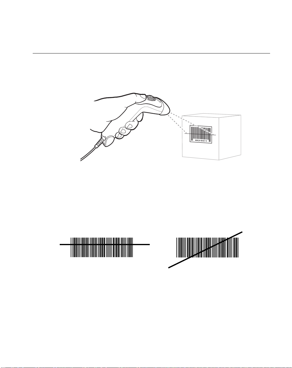
Figure 2-2. Scanning in Hand-Held Mode
1. Ensure all connections are secure. (Refer to the host chapter for your scanner.)
2. Aim the scanner at the bar code. If your scanner has a trigger, aim and press the
trigger. (See Aiming on page 2-6 and Decode Zones on page 2-7.)
3. Ensure the scan line crosses every bar and space of the symbol.
RIGHT
012345
4. Upon successful decode, the scanner beeps and the LED turns green. (For more
information on beeper and LED definitions, refer to Table 2-1 and Table 2-2.)
012345
2-5
Page 28

QuickScan QS3000/QS3500 Product Reference Guide
Aiming
Do not hold the scanner directly over the bar code. Laser light reflecting directly back into
the scanner from the bar code is known as specular reflection. This specular reflection can
make decoding difficult.
Y ou can tilt the scanner up to 65
° forward or back and achieve a successful decode (Figure
2-3). Simple practice quickl y show s what tol eranc es to work within.
Specular
Reflection
+ 4
-
65
Bar
Code
65
Figure 2-3. Maximum Tilt Angles and Dead Zone
2-6
Page 29

Decode Zones
W
i
d
t
h
o
f
F
i
e
l
d
N
ote: Typical performance at 73˚ F (23˚ C) on
high quality symbols in normal room light.
in. cm
25.4
10
Scanning
QS3000
12.7
5
0
0
5 mil
0
0
0
0
2"
7.5 mil
10 mil
100% UPC
4"
6"
7.5"
5
12.7
10
25.4
in.
cm
20 mil
40 mil
*
55 mil
0
0
5
12.7
10
25.4
11"
12"
12.5"
15
38.1
Depth of Field
*Minimum distance determined by symbol length and scan angle
Figure 2-4. QS3000 Decode Zone
2-7
Page 30

QuickScan QS3000/QS3500 Product Reference Guide
i
d
t
h
o
f
F
i
e
l
d
Note: Typical performance at 73˚ F (23˚ C) on
high quality symbols in normal room light.
QS3500
in. cm
15
10
5
0
38.1
25.4
12.7
0
W
in.
cm
5 mil
7.5 mil
2"
10 mil
100% UPC
4.5"
20 mil
7"
9"
13.5"
40 mil
55 mil
22.5"
25"
0
0
0
0
*
5
12.7
10
25.4
15
38.1
0
0
5
12.7
10
25.4
15
38.1
20
50.8
25
63.5
Depth of Field
*Minimum distance determined by symbol length and scan angle
Figure 2-5. QS3500 Decode Zone
2-8
Page 31
Scanning
Scanning in Hands-Free Mode
The QS3000 Series Intellistand adds greater flexibility to your scanning operation. Refer to
Assembling the Stand, Mounting the Stand (optional), and Scanning in the Stand for
detailed information about hands-free scanning.
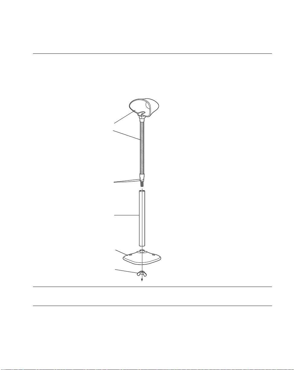
Assembling the Stand
1.Unscrew the wingnut
One piece scanner
“cup” with flexible neck.
Flat areas
Tubular neck
enclosure
from the bottom of the
one piece scanner
“cup”.
2.Insert the neck of the
scanner “cup” into the
tubular neck
enclosure.
3.Fit the bottom of the
neck piece into the
opening on the top of
the stand base.
4.Tighten the wing nut
underneath the base
to secure the cup and
neck piece to the b ase
(see the note below).
5.Bend the neck to the
Stand base
Wingnut
desired position for
scanning.
Note:Before tightening the wingnut under the base, ensure that the flat
areas on the flexible neck fit securely in the grooves in the base.
2-9
Page 32

QuickScan QS3000/QS3500 Product Reference Guide
Mounting the Stand (optional)
Y ou can attach the base of the scanner’s stand to a flat surface using two screws or doublesided tape (not provided).
Two screw-mount holes.
Double-sided tape
areas
(3 places)
dimensions = 1” x 2”)
Figure 2-6. Mounting the Stand
Screw Mount
1. Position the assembled base on a flat surface.
2. Screw one #10 wood screw into each screw-mount hole until the base of the stand
is secure (see Figure 2-6).
Tape Mount
1. Peel the paper liner off one side of each piece of tape and place the sticky surface
over each of the three rectangular tape holders.
2. Peel the paper liner off the exposed sides of each piece of tape and press the stand
on a flat surface until it is secure (see Figure 2-6).
Note:Mounting the stand is optional.
2-10
Page 33

Scanning
Scanning in the Stand
When seated in the stand’s “cup”, the scanner’s built-in sensor places the scanner in
Intellistand mode. When the scanner is removed from the stand it operates in its normal
hand-held mode (e.g., Intellistand mode or trigger mode, depending on the model and
configuration).
Figure 2-7. Inserting and Using the Scanner in the Stand
Intellistand operation:
1. Ensure all cable connections are secure.
2. Insert the scanner in the optional hands-free stand by placing the front of the
scanner into the stand’s “cup” (see Figure 2-7). When not in use, the scanner’s
laser is in a blinking state.
3. To scan a bar code, present the bar code and ensure the scan line crosses every
bar and space of the symbol. (See Aiming on page 2-6 and Decode Zones on page
2-7.)
4. The scan beam becomes steady when the scanner detects the bar code.
5. Upon successful decode, the scanner beeps and the LED turns green.
2-11
Page 34

QuickScan QS3000/QS3500 Product Reference Guide
2-12
Page 35

Chapter 3
Maintenance and Technical Specifications
Introduction
This chapter covers suggested scanner maintenance, troubleshooting, technical
specifications, and signal descriptions (pinouts).
Maintenance
Cleaning the exit window is the only maintenance required. A dirty window may affect
scanning accuracy.
• Do not allow any abrasive material to touch the window
• Remove any dirt particles with a damp cloth
• Wipe the window using a tissue moistened with ammonia/water
• Do not spray water or other cleaning liquids directly into the window
• Do not remove the rubber nose of the scanner.
3-1
Page 36

QuickScan QS3000/QS3500 Product Reference Guide
Troubleshooting
Problem Possible Causes Possible Solutions
Table 3-1. Troubleshooting
Nothing happens when
you follow the operating
instructions, or the
scanner displays erratic
behavior (laser does not
come on, scanner emits
frequent beeps).
Laser comes on, but
symbol does not decod e.
Symbol is decoded, but
not transmitted to the
host.
No power to the scanner. Check the system power. Ensure the
power supply is connected if your
configuration requires a power supply.
Interface/power cables are
loose.
Scanner is not programmed
for the correct bar code type.
Bar code symbol is
unreadable.
Distance between scanner
and bar code is incorrect.
Scanner is not programmed
for the correct host type.
Check for loose cable connections.
Be sure the scanner is programmed to
read the type of bar code you are
scanning.
Check the symbol to make sure it is not
defaced. Try scanning test symbols of
the same bar code type.
Move the scanner closer to or further
from the bar code.
Scan the appropriate host typ e bar code.
3-2
Page 37

Problem Possible Causes Possible Solutions
Scanned data is
incorrectl y displayed on
the host.
Note:If after performing these checks the symbol still does not scan,
contact your distributor or call the local PSC Inc. Support Center.
See page xii for the telephone numbers.
Maintenance and Technical Specifications
Table 3-1. Troubleshooting (Continued)
Scanner is not programmed to
work with the host. Check
scanner host type parame ters
or editing options.
Be sure proper host is selected. (See th e
host chapter for your scanner.)
For RS-232, ensure the scanner’s
communication parameters match the
host’s setting s.
For a USB HID keyboard or a keyboard
wedge configur ati on, en sure the system
is programmed for the correct keyboard
type and language, and the CAPS LOCK
key is in the cor rect state.
Be sure editing options (e.g., ADF, UPCE to UPC-A Conversion) are properly
programmed.
3-3
Page 38

QuickScan QS3000/QS3500 Product Reference Guide
Technical Specifications
T able 3-2. Technical Specifications
Item Description
Power Requirements
Stand-By Current 1 mA (max)
Power Source Decoded:
Decode Capability
Beeper Operation User-selectable: Enable, Disable
Beeper Volume User-selectable: three levels
QS 3000:
4.5 – 5.5 VDC @ 145 mA nominal
QS3500:
4.5 – 5.5 VDC @ 145 mA nominal (decoded)
4.75 – 14.0 VDC @ 100 mA nominal (undecoded)
Depending on host:
• Host powered
• External power supply
Undecoded:
Power supplied by interface controller
Decoded:
UPC/EAN, UPC/EAN with supplementals, UCC/EAN
128, Code 39, Code 39 Fu ll ASCII, Code 3 9 Trioptic,
Codabar (NW7), Interleaved 2 of 5, Discrete 2 of 5,
Code 128, Code 93, MSI, Code 11, UCC/EAN RSS,
Code 32, Coupon Code, and Bookland EAN
Undecoded:
Determined by interface controller
Beeper Tone User-selectable: three tones
Decode Depth of Field Refer to QS3000 Decode Zone on page 2-7and
QS3500 Decode Zone on page 2-8.
Scan Repetition Rate Approximately 44 scans/sec. (bidirectional)
Skew Tolerance ± 60° min. (from normal)
Pitch Tolerance ± 65° (from normal)
Roll Tolerance ± 10° (from normal) dependent on bar code height
3-4
Page 39

Maintenance and Technical Specifications
T able 3-2. Technical Specifications (Continued)
Item Description
Print Contrast Minimum 25% minimum r eflectance differential, measured at
650 nm.
Ambient Light Immunity
Indoor:
Outdoor:
Durability 5 ft (1.5 m) drops to concrete
Operating Temperature 32° to 104° F (0° to 40° C)
Storage Temperature -40° to 140° F (-40° to 60° C)
Humidity 5% to 95% (non-condensing)
450 Ft Cand les (4,842 Lux)
8,000 Ft Candles (86,112 Lux)
Weight (without cable)
Dimensions:
Height
Width
Depth
Laser
Laser Classifications CDRH Class 2 (QS3500)
ESD 15 kV air discharge
Minimum Element Widt h 5 mil (0.127 mm)
Interfaces Supported
4.2 oz. (120 g)
5.3 in. (13.5 cm)
2.5 in. (6.4 cm)
2.2 in. (5.6 cm)
650nm laser diode
IEC 825-1 Class 1 (QS3000)
8 kV contact discharge
Decoded:
RS-232, Keyboard Wedge, Wand Emulation, IBM
468X/469X, USB, Synapse
Undecoded:
Undecoded (Decoding is based on interface controller)
3-5
Page 40

QuickScan QS3000/QS3500 Product Reference Guide
rt
Scanner Signal Descriptions
Bottom of scanner
Cable interface po
PIN 10
Interface cable
modular connector
Figure 3-1. Scanner Cable Pinouts
PIN 1
3-6
Page 41

Maintenance and Technical Specifications
The signal descriptions in Table 3-3 apply to the connector on the scanner and are for
reference only.
Table 3-3. Scanner Signal Pin-outs
QS3000 QS3500
Keyboard
Pin IBM Synapse RS-232
1 Reserved Reserved SynClock Reserved Reserved Reserved Jump to Pin 6
2 Power Power Power Power Power Power Power
3 Ground Ground Ground Ground Ground Ground Ground
4 Enable IBM_A(+) Reserved TxD KeyClock Bar Data Reserved
5 SOS Reserved Reserved RxD TermData CTS D +
6 Trigger* IBM_B(-) SynData RTS KeyData RTS Jump to Pin 1
7 Good Read Reserved Reserved CTS TermClock Reserved D -
8 Bar Data Reserved Reserved Reserved Reserved Reserved Reserved
9 Reserved Reserved Reserved Reserved Reserved Reserved Reserved
Wedge Wand USB
10 Reserved Reserved Reserved Reserved Reserved Reserved Reserved
3-7
Page 42

QuickScan QS3000/QS3500 Product Reference Guide
3-8
Page 43

Chapter 4
User Preferences
Introduction
You have the option to program the QS3x00 scanner to perform various functions, or
activate different features. This chapter describes each user preference feature and
provides the programming bar codes necessary for selecting these features for your
QS3x00 scanner. For the undecoded QS3500 scanner, refer to the programming guide for
your external interface controller or portable terminal. Before programming, follow the
instructions in Ch apte r 1, Getting Started.
Your QS3x00 is shipped with the settings shown in the User Preferences Default Table on
page 4-3 (also see Appendix A, Standard Default Parameters for all host device and
miscellaneous scanner defaults). If the default values suit your requirements, programming
may not be necessary .
Features values are set by scanning single bar codes or short bar code sequences. The
settings are stored in non-volatile memory and are preserved even when the scanner is
powered down.
4-1
Page 44

QuickScan QS3000/QS3500 Product Reference Guide
If you are not using a Synapse or USB cable you must select a host type (see each host
chapter for specific host information). After you hear the power-up beeps, select a host
type. This only needs to be done once, upon the first power-up when connected to a new
host.
To return all features to their default values, all you need to do is scan the Set All Defaults
bar code on page 4-4. Throughout the programming bar code menus, default values are
indicated with asterisks (
*).
* Indicates Default
*High Frequency
Feature/Option
Scanning Sequence Examples
In most cases you need only scan one bar code to set a specific parameter value. For
example, if you want to set the beeper tone to high, simply scan the High Frequency
(beeper tone) bar code listed under Beeper T one on page 4-6. The scanner issues a short
high beep and the LED turns green, signifying a successful parameter entry.
Other parameters, such as specifying Serial Response Time-Out or setting Data
Transmission Formats, require that you scan several bar codes. Refer to Host Serial
Response Time-out on page 6-18 and Scan Data Options on page 12-6 for descriptions of
this procedure.
Errors While Scanning
Unless otherwise specified, if you make an error during a scanning sequence, just re-scan
the correct parameter.
4-2
Page 45

User Preferences
User Preferences Default Parameters
Table 4-1 lists the defaults for user preferences parameters. If you wish to change any
option, scan the appropriate bar code(s) provided in the User Preferences section
beginni ng on page 4-4.
Note:See Appendix A, Standard Default Pa ramete r s for all user
preferences, hosts, symbologies, and miscellaneous default
parameters.
T able 4-1. User Preferences Default Table
Page
Parameter Default
User Preferences
Set Default Parameter All Defaults 4-4
Number
Trigger Mode Trigger M ode (triggered
unit only)
Beeper Tone High Frequency 4-6
Beeper Vol ume High Volum e 4-7
Laser On Time 3.0 Sec 4-8
Beep After Good Decode Enable 4-9
4-5
4-3
Page 46

QuickScan QS3000/QS3500 Product Reference Guide
User Preferences
Set Default Parameter
Scanning this bar code returns all parameters to the default values listed in Table A-1 on
page A-1.
Set All Defaults
4-4
Page 47

User Preferences
Trigger Mode
This parameter is for “triggered” models only. Scan the Triggerless Mode bar code to
turn off trigger functionality and place the scanner in constant on mode. In constant on
mode, the trigger has no effect. The laser is constantly on and blinking as if it was in a scan
stand. Scan the Trigger Mode bar code to activate the trigger and turn off constant on
mode.
*Trigger Mode
Triggerless Mode
4-5
Page 48

QuickScan QS3000/QS3500 Product Reference Guide
Beeper Tone
T o select a decode beep frequency (tone), scan the Low Frequency, Medium Frequency,
or High Frequency bar code.
Low Frequency
Medium Frequency
4-6
*High Frequency
Page 49

User Preferences
Beeper Volume
To select a beeper volume, scan the Low Volume, Medium Volume, or High Volume bar
code.
Low Volume
Medium Volume
*High Volume
4-7
Page 50

QuickScan QS3000/QS3500 Product Reference Guide
Laser On Time
This parameter sets the maximum time that decode processing continues during a scan
attempt. It is programmable in 0.1 second increments from 0.5 to 9.9 seconds. The default
Laser On Time is 3.0 seconds.
To set a Laser On Time, scan the bar code below. Next, scan two numeric bar codes
beginni ng on page D-1 in Appendix D that correspond to the desired on time. Single digit
numbers must have a leading zero. For example, to set an On Time of 0.5 seconds, scan
the bar code below, then scan the “0” and “5” bar codes. If you make an error, or wish to
change your selection, scan Cancel on page D-5.
4-8
Laser On Time
Page 51

User Preferences
Beep After Good Decode
Scan a bar code below to select whether or not the scanner beeps after a good decode. If
Do Not Beep After Good Decode is selected, the beeper still operates during parameter
menu scanning and indicates error conditions.
*Beep After Good Decode
(Enable)
Do Not Beep After Good Decode
(Disable)
4-9
Page 52

QuickScan QS3000/QS3500 Product Reference Guide
4-10
Page 53

Chapter 5
Keyboard Wedge Interface
Introduction
This chapter covers Keyboard Wedge interface information for setting up your scanner.
This interface type is used to attach the scanner between the keyboard and host computer.
The scanner translates the bar code data into keystrokes. The host computer accepts the
keystrokes as if they originate from the keyboard.
This mode of operation allows adding bar code reading functionality to a system designed
for manual keyboard input. In this mode the keyboard keystrokes are simply passed
through.
Throughout the programming bar code menus, default values are indicated with asterisks
(
*).
* Indicates Default
*North American
Feature/Option
5-1
Page 54

QuickScan QS3000/QS3500 Product Reference Guide
Connecting a Keyboard Wedge Interface
Male DIN Keyboard Connector to Host
Y-cable
Power supply
(if needed)
Figure 5-1. Keyboard Wedge Connection with Y-cable
To connect the Keyboard Wedge Y-cable:
1. Switch off the host and unplug the keyboard connector.
2. Attach the modular connector of the Y-cable to the cable interface port on the
scanner. (See Installing the Interface Cable on page 1-3.)
3. Connect the round male DIN host connector of the Y-cable to the keyboard port on
the host device.
4. Connect the round female DIN keyboard connector of the Y -cable to the keyboard.
5. If needed, attach the optional power supply to the connector in the middle of the Y cable.
6. Ensure that all connections are secure.
7. Switch on your host system.
8. Scan the appropriate bar codes in this chapter to configure the scanner.
5-2
Page 55

Keyboard Wedge Interfac e
Keyboard Wedge Default Parameters
T able 5-1 lists the defaults for Keyboard Wedge host parameters. If you wish to change any
option, scan the appropriate bar code(s) provided in the Keyboard Wedge Host Parameters
section beginning on page 5-4.
Note:See Appendix A, Standard Default Pa ramete r s for all user
preferences, hosts, symbologies, and miscellaneous default
parameters.
Table 5-1. Keyboard Wedge Host Default Table
Page
Parameter Default
Keyboard Wedge Host Parameters
Number
Keyboard Wedge Host Type IBM PC/AT & IBM PC
Compatibles
Country Types (Country Codes) North American 5-6
Ignore Unknown Characters Ignore 5-8
Keystroke Delay No Delay 5-9
Intra-Keystroke Delay Disable 5-10
Alternate Numeric Keypad Emulation Disable 5-10
CAPS Lock On Disable 5-11
CAPS Lock Override Disable 5-11
1
User selection is required to configure this interface and this is the most common selection.
1
5-4
5-3
Page 56

QuickScan QS3000/QS3500 Product Reference Guide
Keyboard Wedge Host Parameters
Keyboard Wedge Host Types
Select your keyboard wedge host by scanning one of the bar codes below.
IBM PC/AT & IBM PC Compatibles
IBM PS/2 (Model 30)
1
5-4
Page 57

Keyboard Wedge Interfac e
Keyboard Wedge Host Types (continued)
IBM AT NOTEBOOK
IBM XT
NCR 7052
Note:1User selection is required to configure this interface and this is the
most common selection.
5-5
Page 58

QuickScan QS3000/QS3500 Product Reference Guide
Keyboard Wedge Country Types (Country Codes)
Scan the bar code corresponding to your keyboard type. If your particular keyboard type is
not listed, see Alternate Numeric Keypad Emulation on page 5- 10.
*North American
German
5-6
French
French Canadian
Page 59

Keyboard Wedge Interfac e
Keyboard Wedge Country Types (continued)
Spanish
Italian
Swedish
UK English
Japanese
5-7
Page 60

QuickScan QS3000/QS3500 Product Reference Guide
Ignore Unknown Characters
Unknown characters are characters the host does not recognize. When Ignore Unknown
Characters is selected, all bar code data is sent except for unknown characters, and no
error beeps sound on the scanner. When Do Not Ignore Unknown Characters is
selected, bar code data is sent up to the first unknown character and then four (error) beeps
sound on the scanner.
*Ignore Unknown Characters
5-8
Do Not Ignore Unknown Characters
Page 61

Keyboard Wedge Interfac e
Keystroke Delay
This is the delay in milliseconds between emulated keystrokes. Scan a bar code below to
increase the delay when hosts require a slower transmission of data.
*No Delay
Medium Delay (20 msec)
Long Delay (40 msec)
5-9
Page 62

QuickScan QS3000/QS3500 Product Reference Guide
Intra-Keystroke Delay
When enabled, an additional delay is inserted between each emulated key depression and
release. This sets the Keystroke Delay parameter to a minimum of 5 msec.
Enable
*Disable
Alternate Numeric Keypad Emulation
This allo ws e m ul a ti o n of mo st ot he r c oun t ry ke yb oa rd t y pe s no t l i s ted i n Keyboard Wedge
Country Types (Country Codes) on page 5-6 in a Microsoft operating system environment.
Enable Alternate Numeric Keypad
*Disable Alternate Numeric Keypad
5-10
Page 63

Keyboard Wedge Interfac e
CAPS Lock On
When enabled, the scanner emulates keystrokes as if the Caps Lock key is always
pressed.
Enable Caps Lock On
*Disable Caps Lock On
CAPS Lock Override
When enabled, on AT or AT Notebook hosts, the keyboard ignores the state of the Caps
Lock key. Therefore, an ‘A’ in the bar code is sent as an ‘A’ no matter what the state of the
keyboard’s Caps Lock key.
Enable Caps Lock Override
*Disable Caps Lock Override
Note:If both CAPS Lock On and CAPS Lock Override are enabled, CAPS
Lock Override takes precedence.
5-11
Page 64

QuickScan QS3000/QS3500 Product Reference Guide
Keyboard Maps
The following keyboard maps are provided for prefix/suffix keystroke parameters. To
program the prefix/suffix values, see the bar codes on page12-5.
7014 5001 5002 5003 5004 5005 5006 5007 5008 5009 5010
7009
Figure 5-2. IBM PS2 Type Keyboard
.
5001
5003
5005
5007
5009
5002
5004
5006
5008
5010
7014
7009
5011
7008
7013
7013
5012
7003
7012
7011
7002 7004 7005
7008
7012
7013
7004
7011 7002
7003
7006
5-12
Figure 5-3. IBM PC/XT
Page 65

Keyboard Wedge Interfac e
5001
5003
5005
5007
5009
5002
5004
5006
5008
5010
7009
5002
5001
5003
5004
5005 5006
5007
5008
5009
5010
Figure 5-4. IBM PC/AT
5011
1048
5012
(1048 if double key)
1046
7008
7013
1045
5013
5014
5015
1043
5016
5018
5017
7013
5019
(7013 if double key)
7014
7012
7004
7011
7003
7002
Figure 5-5. NCR 7052 32-KEY
5-13
Page 66
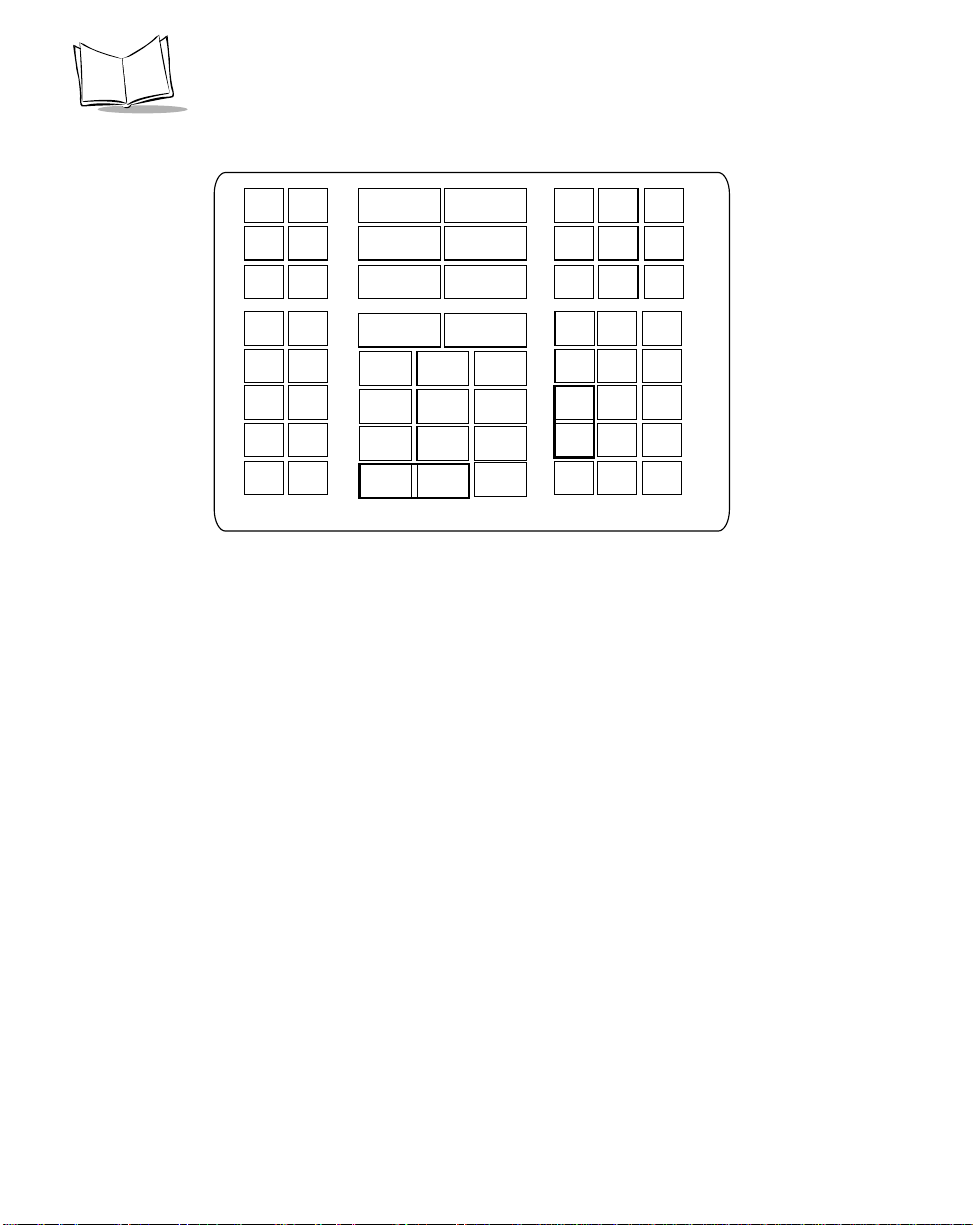
QuickScan QS3000/QS3500 Product Reference Guide
1066
1065
1072
1073
1079 1080
5002
5001
5003
5004
5005 5006
5007
5008
5009
5010
5012
1068
1075
1082
1046
1069
1076
1083 1084
1045
5014
1043
5017
7013
(1043 if double key)
1067
1074
1081
5011
1048
(1048 if double key)
Figure 5-6. NCR 7052 58-KEY
1070
1077
5013
5015
5016
5018
5019
1071
1078
1085
1086
1087
1088
1089
1090
5-14
Page 67

ASCII Character Set
Note:Code 39 Full ASCII interprets the bar code special character
($ + % /) preceding a Code 39 character and assigns an ASCII
character value to the pair. For example, when Code 39 Full ASCII
is enabled and a +B is scanned, it is interpreted as b, %J as ?, and
%V as @. Scanning ABC%I outputs the keystroke equivalent of
ABC >.
Table 5-2. Keyboard Wedge ASCII Character Set
Keyboard Wedge Interfac e
ASCII
Value
1001 $A CTRL A
1002 $B CTRL B
1003 $C CTRL C
1004 $D CTRL D
1005 $E CTRL E
1006 $F CTRL F
1007 $G CTRL G
1008 $H CTRL H
1009 $I CTRL I
1010 $J CTRL J
1011 $K CTRL K
1012 $L CTRL L
1013 $M CTRL M
1014 $N CTRL N
1015 $O CTRL O
1016 $P CTRL P
Full ASCII
Code 39
Encode Char.
Keystroke
1017 $Q CTRL Q
5-15
Page 68

QuickScan QS3000/QS3500 Product Reference Guide
Table 5-2. Keyboard Wedge ASCII Character Set (Continued)
1018 $R CTRL R
1019 $S CTRL S
1020 $T CTRL T
1021 $U CTRL U
1022 $V CTRL V
1023 $W CTRL W
1024 $X CTRL X
1025 $Y CTRL Y
1026 $Z CTRL Z
1032 Space Space
1033 /A !
1034 /B ‘
1035 /C #
1036 /D E
1037 /E %
5-16
1038 /F &
1039 /G ‘
1040 /H (
1041 /I )
1042 /J *
1043 /K +
1044 /L ,
1045 - 1046 . .
1047 / /
1048 0 0
1047 1 1
Page 69

Keyboard Wedge Interfac e
Table 5-2. Keyboard Wedge ASCII Character Set (Continued)
1050 2 2
1051 3 3
1052 4 4
1053 5 5
1054 6 6
1055 7 7
1056 8 8
1057 9 9
1058 /Z :
1059 %F ;
1060 %G <
1061 %H =
1062 %I >
1063 %J ?
1064 %V @
1065 A A
1066 B B
1067 C C
1068 D D
1069 E E
1070 F F
1071 G G
1072 H H
1073 I I
1074 J J
1075 K K
1076 L L
5-17
Page 70

QuickScan QS3000/QS3500 Product Reference Guide
Table 5-2. Keyboard Wedge ASCII Character Set (Continued)
1077 M M
1078 N N
1079 O O
1080 P P
1081 Q Q
1082 R R
1083 S S
1084 T T
1085 U U
1086 V V
1087 W W
1088 X X
1089 Y Y
1090 Z Z
1091 %K [
5-18
1092 %L \
1093 %M ]
1094 %N ^
1095 %O _
1096 %W ‘
1097 +A a
1098 +B b
1099 +C c
1100 +D d
1101 +E e
1102 +F f
1103 +G g
Page 71

Keyboard Wedge Interfac e
Table 5-2. Keyboard Wedge ASCII Character Set (Continued)
1104 +H h
1105 +I i
1106 +J j
1107 +K k
1108 +L l
1109 +M m
1110 +N n
1111 +O o
1112 +P p
1113 +Q q
1114 +R r
1115 +S s
1116 +T t
1117 +U u
1118 +V v
1119 +W w
1120 +X x
1121 +Y y
1122 +Z z
1123 %P {
1124 %Q |
1125 %R }
1126 %S ~
1127 Undefined
1128
5-19
Page 72

QuickScan QS3000/QS3500 Product Reference Guide
Table 5-2. Keyboard Wedge ASCII Character Set (Continued)
ALT Keys Keystroke
2065 ALT A
2066 ALT B
2067 ALT C
2068 ALT D
2069 ALT E
2070 ALT F
2071 ALT G
2072 ALT H
2073 ALT I
2074 ALT J
2075 ALT K
2076 ALT L
2077 ALT M
2078 ALT N
5-20
2079 ALT O
2080 ALT P
2081 ALT Q
2082 ALT R
2083 ALT S
2084 ALT T
2085 ALT U
2086 ALT V
2087 ALT W
2088 ALT X
2089 ALT Y
2090 ALT Z
Page 73

Keyboard Wedge Interfac e
Table 5-2. Keyboard Wedge ASCII Character Set (Continued)
PF Keys Keystrokes
4001 PF 1
4002 PF 2
4003 PF 3
4004 PF 4
4005 PF 5
4006 PF 6
4007 PF 7
4008 PF 8
4009 PF 9
4010 PF 10
4011 PF 11
4012 PF 12
4013 PF 13
4014 PF 14
4015 PF 15
4016 PF 16
4017 PF 17
4018 PF 18
4019 PF 19
4020 PF 20
4021 PF 21
4022 PF 22
4023 PF 23
4024 PF 24
F Keys Keystroke
5001 F1
5-21
Page 74

QuickScan QS3000/QS3500 Product Reference Guide
Table 5-2. Keyboard Wedge ASCII Character Set (Continued)
5002 F2
5003 F3
5004 F4
5005 F5
5006 F6
5007 F7
5008 F8
5009 F9
5010 F10
5011 F11
5012 F12
5013 F13
5014 F14
5015 F15
5016 F16
5-22
5017 F17
5018 F18
5019 F19
5020 F20
5021 F21
5022 F22
5023 F23
5024 F24
5025 F25
5026 F26
5027 F27
5028 F28
Page 75

Keyboard Wedge Interfac e
Table 5-2. Keyboard Wedge ASCII Character Set (Continued)
5029 F29
5030 F30
5031 F31
5032 F32
5033 F33
5034 F34
5035 F35
5036 F36
5037 F37
5038 F38
5039 F39
5040 F40
Numeric
Keypad
6042 *
6043 +
6044 undefined
6045 6046 .
6047 /
6048 0
6049 1
6050 2
6051 3
6052 4
6053 5
6054 6
Keystroke
5-23
Page 76

QuickScan QS3000/QS3500 Product Reference Guide
Table 5-2. Keyboard Wedge ASCII Character Set (Continued)
6055 7
6056 8
6057 9
6058 Enter
6059 Num Lock
6060 00
Extended
Keypad
7001 Break
7002 Delete
7003 Pg Up
7004 End
7005 Pg Dn
7006 Pause
7007 Scroll Lock
7008 Backspace
7009 Tab
7010 Print Screen
7011 Insert
7012 Home
7013 Enter
7014 Escape
7015 Up Arrow
7016 Dn Arrow
Keystroke
5-24
7017 Left Arrow
7018 Right Arrow
Page 77

Chapter 6
RS-232 Interface
Introduction
This chapter covers RS-232 host information for setting up your scanner. The RS-232
interface is used to attach the scanner to point-of-sale devices, host computers, or other
devices with an available RS-232 port (e.g., com port).
If your particular host is not listed in Table 6-2, you need to set the communication
parameters to match your host device. To set communication parameters for hosts not
listed, refer to the documentation for the host device.
Throughout the programming bar code menus, default values are indicated with asterisks
(
*).
* Indicates Default
*Baud Rate 9600
Feature/Option
6-1
Page 78

QuickScan QS3000/QS3500 Product Reference Guide
Connecting an RS-232 Interface
This connection is made directly from the scanner to the host computer.
Serial Port Connector to Host
Power supply cable
Interface cable
Interface cable
Power supply
Figure 6-1. RS-232 Direct Connection
1. Connect the RS-232 interface cable to the bottom of the scanner, as described in
Installing the Interface Cable on page 1- 3.
2. Connect the other end of the interface cable to the serial port on the host.
3. Connect the power supply.
4. Scan appropriate bar codes in this chapter to match your host settings.
RS-232 Default Parameters
Table 6-1 lists the defaults for RS-232 host parameters. If you wish to change any option,
scan the appropriate bar code(s) provided in the Parameter Descriptions section beginning
on page 6-4.
6-2
Page 79

Note:See Appendix A, Standard Default Pa ramete r s for all user
preferences, hosts, symbologies, and miscellaneous default
parameters.
Table 6-1. RS-232 Host Default Table
Parameter Default
RS-232 Host Parameters
RS-232 Interface
Page
Number
RS-232 Host Type Standard RS-232
Baud Rate 9600 6-9
Parity None 6-11
Check Receive Errors Enable 6-13
Hardware Handshaking None 6-15
Software Handshaking None 6-16
Host Serial Response Time-out 2 Sec 6-18
RTS Line State Low RTS 6-19
Stop Bit Select 1 Stop Bit 6-11
ASCII Format 8-Bit 6-12
Beep on <BEL> Disable 6-20
Intercharacter Delay 0 msec 6-21
1
User selection is required to configure this interface and this is the most common selection.
1
6-6
6-3
Page 80

QuickScan QS3000/QS3500 Product Reference Guide
RS-232 Host Parameters
Various RS-232 hosts are set up with their own parameter default settings (Table 6-2).
Selecting the ICL, Fujitsu, Wincor-Nixdorf Mode A, or Wincor-Nixdorf Mode B/OPOS
terminal sets the defaults listed below. These defaults take precedence over standard
defaults and remain selected if the Set Defaults bar code is scanned.
T able 6-2. Terminal Specific RS-232
Wincor-
Parameter
Transmit Code ID No Yes Yes Yes Yes
Data Transmission
Format
Suffix CR/LF (7013) CR (1013) CR (1013) CR (1013) CR (1013)
Baud Rate 9600 9600 9600 9600 9600
Parity None Even None Odd Odd
Hardware Handshaking None RTS/CTS
Software Handshaking None None None None None
Serial Response Time-
out
Stop Bit Select One One One One One
ASCII Format 8-Bit 8-Bit 8-Bit 8-Bit 8-Bit
Beep On <BEL> Disable Disable Disable Disable Disable
RTS Line State Low High Low Low Low = No data
Standard
(Default) ICL Fujitsu
Data as is Data/Suffix Data/Suffix Data/Suffix Data/Suffix
None RTS/CTS
Option 3
2 Sec. 9.9 Sec. 2 Sec. 9.9 Sec. 9.9 Sec.
Nixdorf
Mode A
Option 3
Wincor-
Nixdorf
Mode B/
OPOS
RTS/CTS
Option 3
to send
6-4
Page 81

RS-232 Interface
RS-232 Host Parameters (continued)
Selecting the ICL, Fujitsu, Wincor-Nixdorf Mode A, or Wincor-Nixdorf Mode B/OPOS
terminal enables the transmission of code ID characters listed in Table 6-3 below. These
code ID characters are not programmable and are separate from the Transmit Code ID
feature. The Transmit Code ID feature should not be enabled for these terminals.
Table 6-3. Terminal Specific Code ID Characters
ICL Fujitsu
UPC-A A A A0 A0
UPC-E E E C0 C0
EAN-8 FF FF B B
EAN-13 FFA A
Code 39 C <len> None M M
Codabar N <len> None N N
Code 128 L <len> None K K
I 2 of 5 I <len> None I I
Code 93 None None L L
D 2 of 5 H <len> None H H
UCC/EAN 128 L <len> None P P
MSI None None O O
Bookland EAN FFA A
Trioptic None None None None
Code 11 None None None None
RSS 14 None None None E
RSS Limited None None None E
RSS Expanded None None None E
Wincor-Nixdorf
Mode A
Wincor-Nixdorf
Mode B/OPOS
6-5
Page 82

QuickScan QS3000/QS3500 Product Reference Guide
RS-232 Host Types
Select an RS-232 host by scanning one of the bar codes below.
Standard RS-232
ICL RS-232
Wincor-Nixdorf RS-232 Mode A
1
Wincor-Nixdorf RS-232 Mode B
Note:1User selection is required to configure this interface and this is the
most common selection.
6-6
Page 83

RS-232 Host Types (continued)
OPOS
Fujitsu RS-232
RS-232 Interface
6-7
Page 84

QuickScan QS3000/QS3500 Product Reference Guide
Baud Rate
Baud rate is the number of bits of data transmitted per second. The scanner’s baud rate
setting should match the baud rate setting of the host device. If not, data may not reach the
host device or may reach it in distorted form.
Baud Rate 600
Baud Rate 1200
6-8
Baud Rate 2400
Baud Rate 4800
Page 85

Baud Rate (continued)
*
Baud Rate 9600
Baud Rate 19,200
RS-232 Interface
Baud Rate 38,400
6-9
Page 86

QuickScan QS3000/QS3500 Product Reference Guide
Parity
A parity check bit is the most significant bit of each ASCII coded character. Select the parity
type according to host device requirements.
Select Odd parity and the parity bit value is set to 0 or 1, based on data, to ensure that an
odd number of 1 bits are contained in the coded character.
Odd
Select Even parity and the parity bit value is set to 0 or 1, based on data, to ensure that an
even number of 1 bits are contained in the coded character.
Even
Select Mark parity and the parity bit is always 1.
Mark
6-10
Page 87

RS-232 Interface
Parity (continued)
Select Space parity and the parity bit is always 0.
Space
Select None when no parity bit is required.
*None
Stop Bit Select
The stop bit(s) at the end of each transmitted character marks the end of transmission of
one character and prepares the receiving device for the next character in the serial data
stream. The number of stop bits selected (one or two) depends on the number the receiving
terminal is programmed to accommodate. Set the number of stop bits to match host device
requirements.
*1 Stop Bit
2 Stop Bits
6-11
Page 88

QuickScan QS3000/QS3500 Product Reference Guide
ASCII Format
This parameter allows the scanner to interface with devices requiring a 7-bit or 8-bit ASCII
protocol.
7-Bit
*8-Bit
6-12
Page 89

RS-232 Interface
Check Receive Errors
Select whether or not the parity, framing, and overrun of received characters are checked.
The parity value of received characters is verified against the parity parameter selected
above.
*Check For Received Errors
(Enable)
Do Not Check For Received Errors
(Disable)
6-13
Page 90

QuickScan QS3000/QS3500 Product Reference Guide
Hardware Handshaking
The data interface consists of an RS-232 port designed to operate either with or without the
hardware handshaking lines, Request to Send (RTS), and Clear to Send (CTS).
If Standard RTS/CTS handshaking is not selected, scan data is transmitted as it becomes
available. If Standard RTS/CTS handshaking is selected, scan data is transmitted
according to the following seque nc e:
• The scanner reads the CTS line for activity. If CTS is asserted, the scanner waits
up to 2 seconds for the host to negate the CTS line. If, after 2 seconds (default),
the CTS line is still asserted, the scanner sounds a transmit error, and any scanned
data is lost.
• When the CTS line is negated, the scanner asserts the RTS line and waits up to 2
seconds for the host to assert CTS. When the host asserts CTS, data is
transmitted. If, after 2 seconds (default), the CTS line is not asserted, the scanner
sounds a transmit error, and discards the data.
• When data transmission is complete, the scanner negates RTS 10 msec after
sending the last character.
• The host should respond by negating CTS. The scanner checks for a negated CTS
upon the next transmission of data.
During the transmission of data, the CTS line should be asserted. If CTS is deasserted for
more than 50 ms between characters, the transmission is aborted, the scanner sounds a
transmission error, and the data is discarded.
If the above communications sequence fails, the scanner issues an error indication. In this
case, the data is lost and must be rescanned.
If Hardware Handshaking and Software Handshaking are both enabled, Hardware
Handshaking takes precedence.
Note:The DTR signal is jumpered to the active state.
6-14
Page 91

RS-232 Interface
None
Scan the bar code below if no Hardware Handshaking is desired.
*None
Standard RTS/CTS
Scan the bar code below to select Standard RTS/CTS Hardware Handshaking.
Standard RTS/CTS
RTS/CTS Option 1
When RTS/CTS Option 1 is selected, the scanner asserts RTS before transmitting and
ignores the state of CTS. The scanner de-asserts RTS when the transmission is complete.
RTS/CTS Option 1
RTS/CTS Option 2
When Option 2 is selected, RTS is always high or low (user-programmed logic level).
However, the scanner waits for CTS to be asserted before transmitting data. If CTS is not
asserted within 2 seconds (default), the scanner issues an error indication and discards the
data.
RTS/CTS Option 2
6-15
Page 92

QuickScan QS3000/QS3500 Product Reference Guide
RTS/CTS Option 3
When Option 3 is selected, the scanner asserts RTS prior to any data transmission,
regardless of the state of CTS. The scanner waits up to 2 seconds (default) for CTS to be
asserted. If CTS is not asserted during this time, the scanner issues an error indication and
discards the data. The scanner de-asserts RTS when transmission is complete.
RTS/CTS Option 3
Software Handshaking
This parameter offers control of the data transmission process in addition to, or instead of,
that offered by hardware handshaking. There are five options.
If Software Handshaking and Hardware Handshaking are both enabled, Hardware
Handshaking takes precedence.
None
When this option is selected, data is transmitted immediately.
*None
6-16
Page 93

RS-232 Interface
ACK/NAK
When this option is selected, after transmitting data, the scanner expects either an ACK or
NAK response from the host. When a NAK is received, the scanner transmits the same data
again and waits for either an ACK or NAK. After three unsuccessful attempts to send data
when NAKs are received, the scanner issues an error indication and discards the data.
The scanner waits up to the programmable Host Serial Response Time-out to receive an
ACK or NAK. If the scanner does not get a response in this time, it issues an error indication
and discards the data. There are no retries when a time-out occurs.
ACK/NAK
ENQ
When this option is selected, the scanner waits for an ENQ character from the host before
transmitting data. If an ENQ is not received within the Host Serial Response Time-out, the
scanner issues an error indication and discards the data. The host must transmit an ENQ
character at least every Host Serial Response Time-out to prevent transmission errors.
ACK/NAK with ENQ
This combines the two previous options.
ACK/NAK with ENQ
ENQ
6-17
Page 94

QuickScan QS3000/QS3500 Product Reference Guide
XON/XOFF
An XOFF character turns the scanner transmission off until the scanner receives an XON
character. There are two situations for XON/XOFF:
• XOFF is received before the scanner has data to send. When the scanner has data
to send, it waits up to 2 seconds for an XON character before transmission. If the
XON is not received within this time, the scanner issues an error indication and
discards the data.
• XOFF is received during a transmission. Data transmission then stops after
sending the current byte. When the scanner receives an XON character, it sends
the rest of the data message. The scanner waits indefinitely for the XON.
XON/XOFF
Host Serial Response Time-out
This parameter specifies how long the scanner waits for an ACK, NAK, or CTS before
determining that a transmission error has occurred. This only applies when in one of the
ACK/NAK Software Handshaking modes, or RTS/CTS Hardware Handshaking option.
6-18
*Minimum: 2 Sec
Low: 2.5 Sec
Page 95

Medium: 5 Sec
High: 7.5 Sec
Maximum: 9.9 Sec
RS-232 Interface
RTS Line State
This parameter sets the idle state of the Serial Host RTS line. Scan a bar code below to
select Low RTS or High RTS line state.
*Host: Low RTS
Host: High RTS
6-19
Page 96

QuickScan QS3000/QS3500 Product Reference Guide
Beep on <BEL>
When this parameter is enabled, the scanner issues a beep when a <BEL> character is
detected on the RS-232 serial line. <BEL> is issued to gain a user’s attention to an illegal
entry or other important event.
Beep On <BEL> Character
(Enable)
*Do Not Beep On <BEL> Character
(Disable)
6-20
Page 97

RS-232 Interface
Intercharacter De la y
This parameter specifies the intercharacter delay inserted between character
transmissions.
*Minimum: 0 msec
Low: 25 msec
Medium: 50 msec
High: 75 msec
Maximum: 99 msec
6-21
Page 98

QuickScan QS3000/QS3500 Product Reference Guide
Prefix / Suffix Values
The values in Table 6-4 can be assigned as prefixes or suffixes for ASCII character data
transmission.
Table 6-4. Prefix/Suffix Values
Full ASCII
Prefix/Suffix Value
1000 %U NUL
1001 $A SOH
1002 $B STX
1003 $C ETX
1004 $D EOT
1005 $E ENQ
1006 $F ACK
1007 $G BELL
1008 $H BCKSPC
Code 39 Encode Character ASCII Character
6-22
1009 $I HORIZ TAB
1010 $J LF/NW LN
1011 $K VT
1012 $L FF
1013 $M CR/ENTER
1014 $N SO
1015 $O SI
1016 $P DLE
1017 $Q DC1
1018 $R DC2
1019 $S DC3
1020 $T DC4
1021 $U NAK
Page 99

Prefix/Suffix Value
1022 $V SYN
1023 $W ETB
1024 $X CAN
1025 $Y EM
1026 $Z SUB
1027 %A ESC
1028 %B FS
1029 %C GS
1030 %D RS
1031 %E US
1032 Space Space
1033 /A !
1034 /B "
RS-232 Interface
T able 6-4. Prefix/Suffix Values (Continued)
Full ASCII
Code 39 Encode Character ASCII Character
1035 /C #
1036 /D $
1037 /E %
1038 /F &
1039 /G ‘
1040 /H (
1041 /I )
1042 /J *
1043 /K +
1044 /L ,
1045 -1046 ..
1047 //
6-23
Page 100

QuickScan QS3000/QS3500 Product Reference Guide
Prefix/Suffix Value
1048 00
1049 11
1050 22
1051 33
1052 44
1053 55
1054 66
1057 77
1056 88
1057 99
1058 /Z :
1059 %F ;
1060 %G <
T able 6-4. Prefix/Suffix Values (Continued)
Full ASCII
Code 39 Encode Character ASCII Character
6-24
1061 %H =
1062 %I >
1063 %J ?
1064 %V @
1065 AA
1066 BB
1067 CC
1068 DD
1069 EE
1070 FF
1071 GG
1072 HH
1073 II
 Loading...