


Version 2018/06/27 Art.No.: 8034359 © 2017 PS Automation GmbH
D
Kurz-Betriebsanleitung PSL
GB
Short Operating Instructions PSL
E
Manual de operación resumido PSL

2

3
D
Inhaltsverzeichnis
4
1. Betriebsbedingungen
2. Handbetätigung
3. Armaturenanbau
4. Elektroanschluss
5. Einstellung der Endschalter
6. Inbetriebnahme
7. Zubehör
GB
Table of content
7
1. Operating conditions
2. Manual operation
3. Valve mounting
4. Electric supply
5. Setting of the limit switches
6. Commissioning
7. Accessories
E
Indice
10
1. Condiciones de operación
2. Operatión manual
3. Montaje sobre la válvula
4. Alimentación eléctrica
5. Ajuste de los finales de carrera
6. Puesta en marcha
7. Accesorios
Änderungen vorbehalten!/ Subject to changes!/
Sujeto a modificaciones!

4
D
Es ist sicherzustellen, dass jede Person, die mit der Aufstellung, Inbetriebnahme, Bedienung,
Wartung und Reparatur der Antriebe beauftragt ist, die ausführliche Betriebsanleitung und
besonders das Kapitel „Sicherheit“ gelesen und verstanden hat.
Vorsicht! Lebensgefährliche elektrische Spannung kann anliegen! Sach- oder
Personenschäden sind durch geeignete Maßnahmen und Einhaltung der
Sicherheitsstandards zu vermeiden!
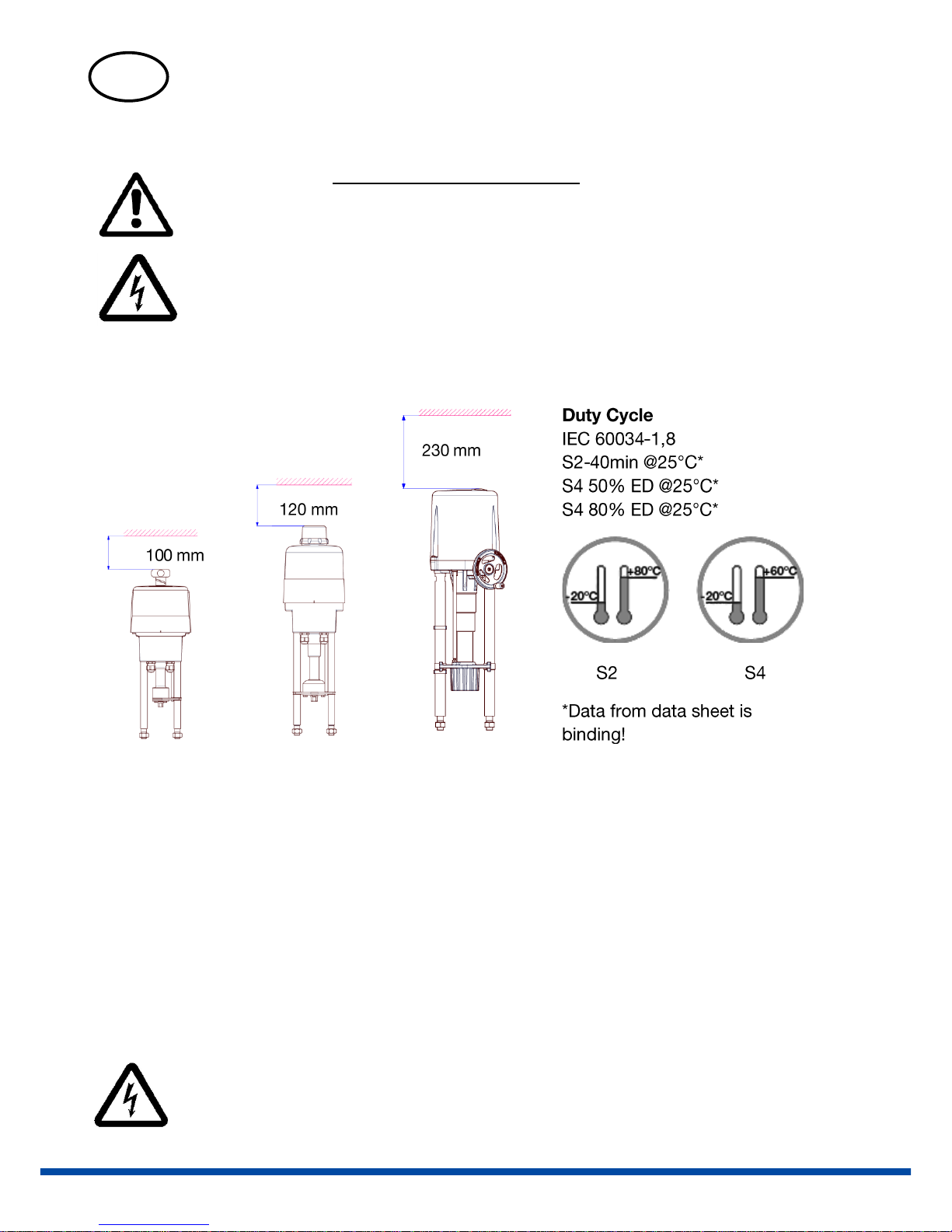
1. Betriebsbedingungen
PSL201-208 PSL214 PSL320-325
Technische Daten siehe Typenschild
2. Handbetätigung
Für Handbetätigung bitte den entsprechenden Aufkleber auf der Antriebshaube beachten!
3. Armaturenanbau
PSL201-214
Bitte beachten Sie die separate Montageanleitung.
PSL320-325
Abhängig vom Ventiltyp.
4. Elektroanschluss
Vor Arbeitsbeginn Netzspannung trennen!
Schaltplan auf Zentralträger!
5
Die Gebäudeinstallation sowie die Überstromschutzeinrichtung und Überspannungsschutzeinrichtungen
müssen entsprechend der Norm DIN IEC 60364-4-41, Schutzklasse I bzw. Schutzklasse III bei 24VAC/24VDC
sowie DIN IEC 60364-4-44 entsprechend der verwendeten Überspannungskategorie des Antriebs
ausgeführt sein.
Alle Netzanschluss- und Steuerleitungen müssen mechanisch durch
geeignete Maßnahmen vor den Anschlussklemmen gegen
unabsichtliches Lösen gesichert werden.
Netzanschluss und Steuerleitungen dürfen nicht zusammen in einer
Leitung geführt werden, es sind stets zwei getrennte Leitungen zu
verwenden!
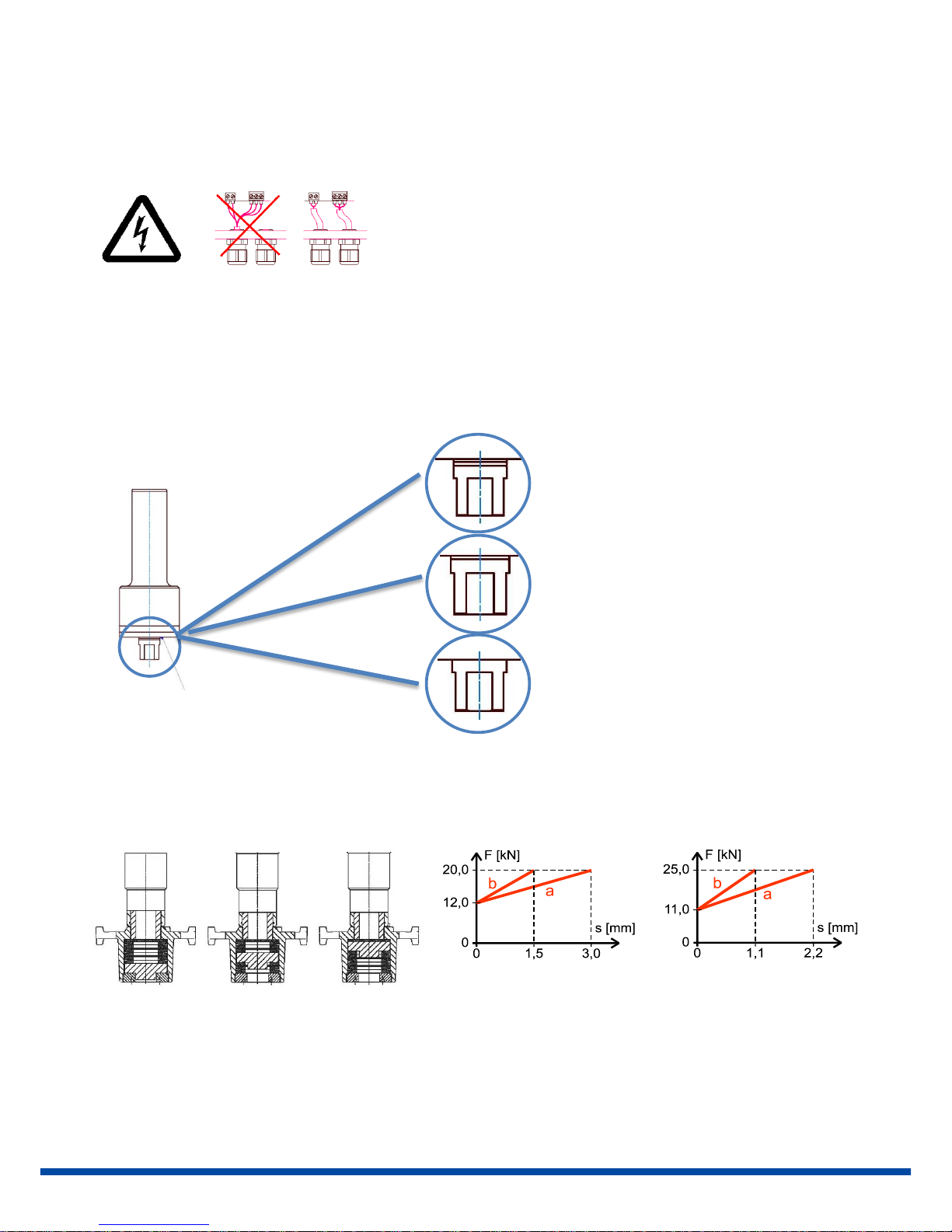
5. Einstellung der Endschalter
Nur bei Lieferung ohne Ventil!
PSL201-214
Nennkraft liegt bei entsprechender
Kerbmarkierung an!
PSL320-325
a b
a PSL320 PSL325
Schaltnocken lösen und verschieben bis Endschalter hörbar klickt.
Oben
Unbelastet
Unten
Kerbmarkierung

6
1 = Schaltnocke Spindelmutter einfahrend
2 = Schaltnocke Spindelmutter ausfahrend
-
6. Inbetriebnahme
Haube schließen und Antrieb per Handrad in die Mitte des Ventilhubes fahren.
Netzspannung einschalten.
Stellsignal für AUF- und ZU- Richtung kurz einschalten und prüfen, ob der Antrieb in die vorgegebene
Richtung positioniert. Gegebenenfalls Stellsignale für AUF / ZU tauschen.
Fahren des Antriebes über die Stellsignale bis zur Abschaltung durch die Endschalter in den jeweiligen
Endlagen. Prüfen, ob die Endlagenabschaltung korrekt ist, gegebenenfalls Endschalter nachjustieren.
7. Zubehör
Für Einbau und Inbetriebnahme des Zubehörs stehen separate Bedienungsanleitungen zur Verfügung.
Zubehör/ Optionen
Versorgungsspannung
230 VAC
1~
115 VAC
1~
24 VAC 1~
400 V 3~
24 VDC
Zusatzwegschalter
2WE • • • •
•
Zusatzwegschalter
Gold
2WE
Gold
• • • • •
Stellungsregler
PSAP
• • • )1
• )2
Stellungsgeber
PSPT
• • • • •
Schaltraum Heizung
HR
• • •
• )3
•
Potentiometer
PD
• • • • •
Wendeschützeinheit
WSM01
•
IP67 Metallhaube
IP
Erhöhung der Schutzart auf IP67
IP68 Metallhaube
IP
Erhöhung der Schutzart auf IP68 (nur gültig für PSL201-214)
• = verfügbar
)1 = PSAP mit externen Relais erforderlich (Version .../R)
)2 = nur mit Wendeschützeinheit möglich
)3 = Versorgungsspannung 24 V oder 115-230 V
2
1
7
GB
Please ensure that the detailed operating instructions and the chapter on "Safety" in
particular have been read and understood by all personnel involved in the installation, startup, operation, maintenance and repair of the actuators.
Caution! Dangerous electrical voltage can be present! Avoid personal or material damages
by observing applicable regulations and safety standards!
1. Operating Conditions
PSL201-208 PSL214 PSL320-325
Please refer to nameplate for technical data
2. Manual Operation
For manual operation, please refer to the individual sticker on the actuator cover.
3. Valve Mounting
PSL201-214
Please refer to the separate mounting instruction.
PSL320-325
Depending on the valve type.
4. Electric Supply
Switch off the mains before starting to work!
Wiring diagram on actuator mainframe!

8
Electric installation as well as over-current and overvoltage protection devices must be conform to the standard DIN
IEC 60364-4-41, protective class I resp. protection class 3 (24VAC/24VDC) and also to the standard DIN IEC 60364-444 according to the applied overvoltage category of the actuator.
Please protect all of the power supply and control cables in front of the
terminals mechanically by using suitable measures against
unintentional loosening. Never install the power supply and the control
cables together in one line but instead please always use two different
lines.
5. Setting of the Limit Switches
Only when supplied without valve!
PSL201-214
Nominal force is applied when respective groove is reached.
PSL320-325
a b
a PSL320 PSL325
Unlock switching cam and move until the switch contact clicks.
Top
Uncompressed
Bottom
Grooves

9
1 = Switching cam retracting spindle nut
2 = Switching cam extending spindle nut
-
6. Commissioning
Close the cover and drive the actuator to the center of the stroke using the handwheel.
Switch on the mains.
Switch the setting signal briefly between OPEN and CLOSE and check that the actuator operates in the
correct direction. If necessary, reverse the setting signal for OPEN / CLOSE.
Drive the actuator, in both directions, using the setting signal until the limit switch cuts-off. Check that
the setting of the limit switch is correct. If necessary re-adjust the limit switches.
7. Accessories
Mounting and commissioning instructions for accessories are available individually.
Accessories/
Options
Supply Voltage
230 VAC
1~
115 VAC
1~
24 VAC 1~
400 V 3~
24 VDC
Position Signal
Switches
2WE
• • • • •
Position Signal
Switches Gold
2WE
Gold
• • • • •
Positioner
PSAP
• • • )1
• )2
Position Transmitter
PSPT
• • • • •
Space Heater
HR
• • •
• )³
•
Potentiometer
PD
• • • • •
Reversing Starter
Contactor
WSM0
1
•
IP67 Metal Cover
IP
Increase of enclosure to IP67
IP68 Metal Cover
IP
Increase of enclosure to IP68 (only valid for PSL201-214)
• = available, for further information see respective datasheet
)1 = PSAP with external relay required
)2 = only to be used with reversing starter contactor
)³ = possible with supply voltage 24 V or 115-230 V
1
2

10
E
Asegurese que todo el personal de puesta en marcha, mantenimiento y de la planta haya
leido detalladamente el manual de operación y mantenimiento. Especialmente el capitulo
de „Seguridad“.
Atención! Puede haber presencia de tensión electrica! Se debe respetar la normativa
vigente de seguridad y de prevención de riesgos laborales!
1. Condiciones de operación
PSL201-208 PSL214 PSL320-325
Consulte la placa de caracteristicas para los datos técnicos.
2. Operación manual
Para la operación manual siga las instrucciones del dibujo situado en la tapa del actuador.
3. Montaje en la válvula
PSL201-214
Consulte el manual de instrucciones adjunto.
PSL320-325
Dependiendo del acoplamiento sobre la válvula.
4. Alimentación eléctrica
Desconecte la alimentación electrica antes de empezar a trabajar!
El esquema electrico se indica en la tapa protectora!
La instalación electrica de las protecciones de sobretensiones y sobreintensidad debe realizarse a acorde a los
estandares DIN IEC 60364-4-41, clase de protección I, clase de protección III (24VAC/24VDC) y también al estandar
DIN IEC 60364-4-44 acorde a la categoria de sobretensión aplicable al actuador.

11
Todos los cables de alimentación y de mando deben protegerse
mecánicamente mediante unas medidas adecuadas para evitar que se
suelten involuntariamente. Nunca instale los cables de alimentación y
mando juntos en una misma linea. Siempre deben ir en 2 lineas
separadas.
5. Ajuste de los finales de carrera
Solo cuando se suministra desmontado de la válvula.
PSL201-214
La fuerza nominal se aplica cuando se llega a la respectiva marca!
PSL320-325
a b a PSL320 PSL325
Desbloquee la leva de acción del final de carrera y desplazela hasta que haga contacto el final de carrera
mecánico.
1 = Leva de ajuste del eje subiendo
2 = Leva de ajuste del eje bajando
Arriba
Posicion reposo
Abajo
Tornillo de bloqueo
Tornillo de
desplazamiento
Marca
1
2
12
6. Puesta en marcha
Cierre la tapa protectora y mueva el actuador a una posición intermedia con el volante
Conecte la alimentación electrica
Envie un comando de ABRIR y CERRAR y compruebe que el actuador gira en el sentido de giro correcto.
En caso de girar al contrario de lo esperado cambie el ajuste de ABRIR y CERRAR.
Mueva el actuador hasta la posición final cerrada y abierta y compruebe que se para por la acción de los
finales de carrera. Reajuste los finales de carrera si fuese necesario.
7. Accesorios
Las instrucciones de montaje y puesta en marcha se entregan indivualmente con cada accesorio.
Accesorios y opciones
Tensión
230 VAC
1~
115 VAC
1~
24 VAC 1~
400 V 3~
24 VDC
2 Finales de carrera
adicionales
2WE
• • • • •
2 Finales de carrera
adicionales chapados
en oro
2WE
Gold
• • • • •
Positionador
PSAP
• • • )1 • )2
Transmisor de
Posición
PSPT
• • • • •
Calentador anticondensación
HR
• • •
• )3 •
Potenciómetro
PD
• • • • •
Contactor reversible
de arranque
WSM01
•
Grado de protección
IP
IP67 con cubierta metálica
Grado de protección
IP
IP68 con cubierta metálica (sólo válido para PSL201-214)
• = disponible, para más información consulte la ficha técnica respectiva
)1 = PSAP con módulo de relé externo requerido
)2 = sólo se debe utilizar con contactor reversible de arranque
)³ = se debe utilizar con tension 24 V o 115-230 V
PS Automation GmbH
Gesellschaft für Antriebstechnik
Philipp-Krämer-Ring 13
D-67098 Bad Dürkheim
Tel.: +49 (0) 63 22 - 94980 – 0
Fax: +49 (0) 63 22 - 94980 – 20
eMail: info@ps-automation.com
www.ps-automation.com
 Loading...