

Version 2019/01/09 Art. No.: 8034352 ©2019 PS Automation GmbH
Inhaltsverzeichnis / Table of content
1. Sicherheit / Safety
2. Einbau / Installation
3. Elektroanschluß / Wiring
4. Inbetriebnahme / Commissioning
5. Sicherheitsfunktion / Safety Function
6. Aktiver Stromausgang / Active Current Feedback
7. Technische Daten / Technical Data
Einbauanleitung PSAP.2A / PSAP.3 für PSL Mod. 4
Installation Instructions PSAP.2A / PSAP.3 for PSL Mod. 4

2
1. Sicherheit / Safety
Vorsicht! Lebensgefährliche elektrische Spannung kann anliegen! Sach- oder Personenschäden sind
durch geeignete Maßnahmen und Einhaltung der Sicherheitsstandards zu vermeiden!
Caution! Dangerous electrical voltage can be present! Avoid personal or material damages by
observing applicable regulations and safety standards!
2. Einbau / Installation
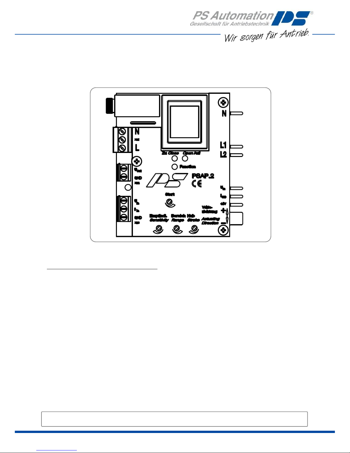
3. Elektroanschluss / Wiring
1. Stellsignal an Klemme X23.
2. Rückmeldesignal an Klemme X22.
3. Spannungsversorgung an Klemme X21.
4. Schutzleiter der Netzversorgung an PE des Antriebsgehäuses
anschließen.
1. Input signal to terminal X23.
2. Feedback signal to terminal X22.
3. Power supply to terminal X21.
4. Connect Protection Earth of the mains supply to the PE of the
actuator housing.
③
Nennspannung von Antrieb und Regler
überprüfen. / Check the nominal voltage of the
positioner and actuator.
Prüfen ob Abstandhalter vorhanden. /
Check whether distance bolt is mounted.
③
③
④
Klemmen festziehen. /
Tighten terminals.
Sicherstellen, dass
Rückmeldepotentiometer
eingebaut ist. /
Check that a feedback
potentiometer is installed.
Zum Einschnappen
auf die Klemmen X22
und X23 drücken -
Biegung der Regler-
Platine vermeiden! /
Press onto blocks X22
and X23 to fit card
into place - avoid
bending of the PSAP-
board!
⑤
①
②
③ ③ ③
③
③
⑥
Kontaktstifte des Reglers PSAP in
Klemmleiste einführen. / Insert contact
pegs of the positioner into the terminals.
③
=
3
4. Inbetriebnahme/ Commissioning
Vorsicht! Lebensgefährliche elektrische Spannung kann anliegen!
Alle Einstellungen mit isoliertem Schraubendreher durchführen!
Benötigtes Werkzeug: Schraubendreher, Messgerät für V, Sollwertgeber (mA oder V).
Caution! Dangerous electrical voltage can be present!
All setting have to be done with an isolated screwdriver!
Needed tools: Screwdriver, measurement instrument for V (0-10), set value source (mA or V).
1. Endschaltereinstellungen des Antriebs überprüfen, ggf. neu einstellen.
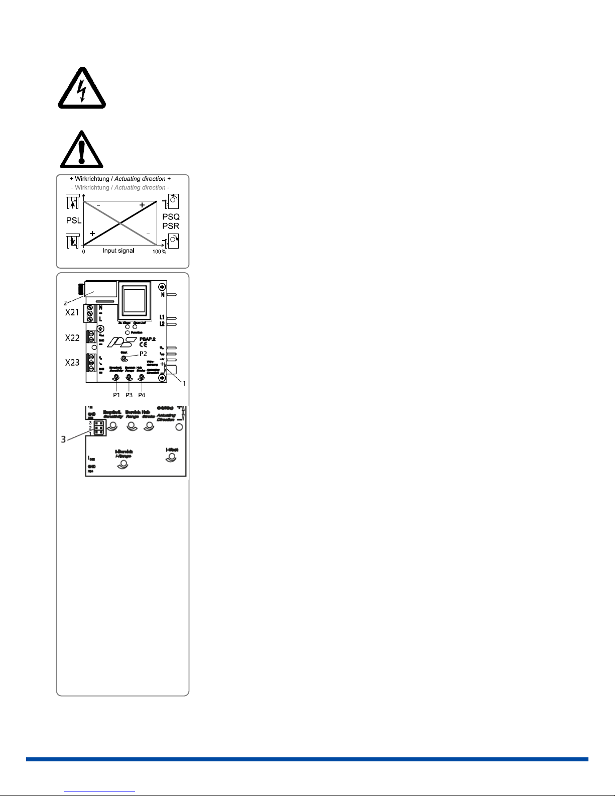
2. Wirkrichtungsschalter (Pos. 1) des Reglers auf die erforderliche Signalzuordnung
einstellen.
3. Empfindlichkeit des Reglers an Potentiometer P1 einstellen (Mittelwert üblich).
4. Potentiometer P2 bis P4 gegen den Uhrzeigersinn an den Anschlag drehen.
5. Messinstrument für 10 VDC an X22 anschließen.
6. Minimales Stellsignal anlegen (0/4 mA bzw. 0/2 V) an X23.
7. Spannungsversorgung an Klemme X21 anlegen und anschließend einschalten, LED
„Function“ leuchtet dauerhaft grün. Antrieb fährt in die entsprechende Endlage und
schaltet über Wegschalter ab.
8. Rückmeldepotentiometer über Rutschkupplung verdrehen, so dass das Messinstrument
an U
out
= 0 V anzeigt.
9. Potentiometer P2 (START) im Uhrzeigersinn drehen, bis beide Laufrichtungs-LEDs
erlöschen.
10. Maximales Stellsignal anlegen (20 mA bzw. 10 V) an X23.
11. Antrieb fährt in die gegenüberliegende Endlage und schaltet über Endschalter ab.
12. Potentiometer P4 (HUB) im Uhrzeigersinn drehen, bis das Messinstrument an U
out
= 10 V
anzeigt.
13. Potentiometer P3 (BEREICH) im Uhrzeigersinn drehen, bis beide Laufrichtungs-LEDs
erlöschen.
14. Stellsignalbereich nochmals durchfahren und prüfen ob der Stellantrieb richtig
positioniert, gegebenenfalls nachjustieren.
15. Bei aktiver Ansteuerung “Open AUF” bzw. „Close ZU“ leuchtet die jeweilige LED.
1. Check the limit switch settings of the actuator, if necessary adjust.
2. Set the direction switch (pos. 1) to the required position.
3. Set the sensitivity of the positioner using potentiometer P1 (usually intermediate value).
4. Turn potentiometers P2, P3, P4 anti-clockwise to the limit.
5. Connect a measuring instrument for 10 VDC to the terminal X22.
6. Set minimum input signal (0/4 mA or 0/2 V) at X23.
7. Connect power supply voltage to terminal X21 and switch on mains supply, the LED
“Function” glows green. The actuator drives to the corresponding end position and stops
due to the position switch.
8. Turn the shaft of the feedback potentiometer via the friction coupling so that the
measuring instrument displays U
out
= 0 V.
9. Turn potentiometer P2 (START) clockwise until both operating LED´s are switched off.
10. Set maximum input signal (20 mA or 10 V) at X23 to the positioner.
11. The actuator drives to the opposite end position and cuts off due to the position switch.
12. Turn potentiometer P4 (STROKE) clockwise until the measuring instrument displays U out
= 10 V.
13. Turn potentiometer P3 (RANGE) clockwise until both operating LED´s are switched off.
14. Check that the actuator positions correctly by driving through the whole input signal
range. If necessary re-adjust.
15. At active signal „Open AUF“ or „Close ZU“ the corresponding LED is on.
1 = Wirkrichtungsschalter
/ direction switch
2 = Sicherung / Fuse
3 = Sicherheitsfunktion
(nur bei PSAP.3) / safety
function (only for PSAP.3)
P1 = Empfindlichkeit /
Sensitivity
P2 = Start
P3 = Bereich / Range
P4 = Hub / Stroke
4
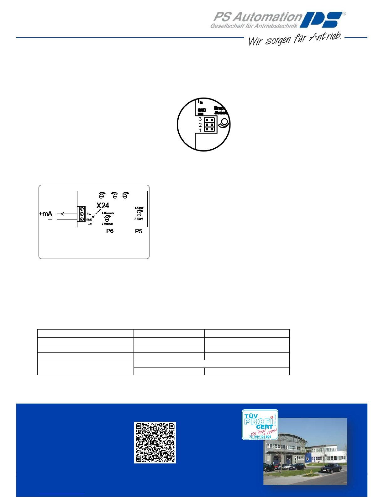
5. Sicherheitsfunktion / Safety function (nur bei PSAP.3 / only at PSAP.3)
Jumperstellung (Pos. 3 auf Seite 3) für Aktion bei Stellsignalausfall. / Jumper setting (key 3 on page 3) to define action at input
signal failure.
1 = Antrieb fährt in Endlage des max. Stellsignals.
2 = Antrieb bleibt stehen.
3 = Antrieb fährt in Endlage des min. Stellsignals.
1 = Actuator drives to position of max. input signal.
2 = Actuator stops.
3 = Actuator drives to position of min. input signal.
6. Aktiver Strom-Ausgang / Active Current Feedback (nur bei PSAP.3 / only at PSAP.3)
1. Inbetriebnahme (4.) muss zuvor durchgeführt worden sein.
2. Messgerät für 20 mA DC an Klemmen X24 anschließen.
3. Antrieb in die Endlage des maximalen Rückmeldewerts fahren.
4. Potentiometer P5 gegen den Uhrzeigersinn an Anschlag drehen.
5. Am Potentiometer P6 anhand des Messgeräts den Signal-
Ausgangsbereich einstellen (16 mA für 4-20 mA Ausgangsignal, 20 mA
für 0-20 mA Ausgangssignal).
6. Den Antrieb in die entgegengesetzte Endlage fahren.
7. Minimales Ausgangssignal (0 mA oder 4 mA) an P5 einstellen.
1. Commissioning as described under 4. must be done first.
2. Connect a measuring instrument for 20 mA DC to terminal block X24.
3. Drive the actuator to the end position that should be displayed with
maximum output signal.
4. Turn potentiometer P5 anti-clockwise until limit is reached.
5. Adjust current range using potentiometer P6 (16 mA for output range 4-
20 mA/20 mA for output range 0-20 mA).
6. Drive actuator to the opposite end position.
7. Adjust minimum output signal (0 mA or 4 mA) using potentiometer P5.
7. Technische Daten / Technical Data
PSAP.2A
PSAP.3
Eingang / Input
0(4)-20 mA / 0(2)-10 V
4-20 mA / 2-10 V
Ausgang / Output
0-10 V
0(4)-20 mA / 0-10 V
Sicherheitsfunktion / Safety Function
Nein / No
Ja / Yes
Bürde / Impedance
I in: 100 Ohm / U in: 50 kOhm
U
out
: > 10 kOhm
I
out
: 300 Ohm / U
out
: > 10 kOhm
PS Automation GmbH
Gesellschaft für Antriebstechnik
Philipp-Krämer-Ring 13
D-67098 Bad Dürkheim
Tel.: +49 (0) 6322 94980-0
E-Mail: info@ps-automation.com
www.ps-automation.com
 Loading...