


Operating Instructions
PS-AMS1x with
Fieldbus-Interface Profibus-DP
Version 2019/01/09 ©2019 PS Automation GmbH
Subject to changes!

2

3
Table of contents
1. Description .................................................................................................................................................................... 4
2. Connecting the Fieldbus ................................................................................................................................................ 4
2.1 Wiring to terminal block ......................................................................................................................................... 4
2.1.1. Termination ..................................................................................................................................................... 5
2.1.2. Fieldbus status LED ......................................................................................................................................... 5
2.2 Connection with Plug & Socket ............................................................................................................................... 5
2.2.1. Termination ..................................................................................................................................................... 5
2.2.2. Fieldbus status LED ......................................................................................................................................... 5
2.3. Slide switch for selecting the communication interface ........................................................................................ 6
3. Fieldbus address ............................................................................................................................................................ 6
4. Process Image ............................................................................................................................................................... 7
4.1. Process Image OUTPUT .......................................................................................................................................... 7
4.1.1. Byte 1 - Set Value High-Byte ........................................................................................................................... 7
4.1.2. Byte 2 - Set Value Low-Byte ............................................................................................................................ 7
4.1.3. Byte 3 - Process Sensor High-Byte .................................................................................................................. 8
4.1.4. Byte 4 - Process Sensor Low-Byte ................................................................................................................... 8
4.1.5. Byte 5 - Command ........................................................................................................................................... 8
4.1.6. Byte 6 - Address .............................................................................................................................................. 8
4.1.7. Byte 7 - Data-High ........................................................................................................................................... 8
4.1.8. Byte 8 - Data-Low ............................................................................................................................................ 8
4.2. Process Image INPUT ............................................................................................................................................. 8
4.2.1. Byte 1 - Actual Value High-Byte ...................................................................................................................... 8
4.2.2. Byte 2 - Actual Value Low-Byte ....................................................................................................................... 8
4.2.3. Byte 3 - Working Condition / Error Code of the Actuator .............................................................................. 8
4.2.4. Byte 4 - Address .............................................................................................................................................. 9
4.2.5. Byte 5 - Data-High ........................................................................................................................................... 9
4.2.6. Byte 6 - Data-Low ............................................................................................................................................ 9
5. Diagnosis ..................................................................................................................................................................... 10
6. Technical Data ............................................................................................................................................................. 10
7. GSD-File ....................................................................................................................................................................... 11
8. Parameter Storage Addresses ..................................................................................................................................... 11
9. Simulation of Profibus-environment........................................................................................................................... 11
10. Hints for Programming .............................................................................................................................................. 11
Annex: Process Image Profibus-DP in PS-AMS ................................................................................................................ 13

4
1. Description
The optional fieldbus-interface Profibus-DP (DPV0, DPV1 and Publisher Support of DPV2) allows operation of the
actuator via Profibus-DP. This interface communicates to the actuator via the standard serial port. The actuator does
then not use analogue set values. Feedback from a process sensor to the optionally available process controller PSIC
integrated in the actuator is digitally transmitted as well. Command level allows on request to read out all
parameters and diagnostics data.
Adjustment of parameterisation of the actuator is not possible via fieldbus.
Note: The actuator has a single communication port. This is used when the optional fieldbus interface is installed.
For parameterisation of the actuator with the communication software PSCS or handheld unit PSC, the position of a
switch on the main board of the actuator PS-AMS1x has to be changed, see chapter 2.3. After that, communication
with PC is possible via the date cable. After parameterisation, the switch has to be placed to position “Fieldbus”
again, to allow communication of the fieldbus module to the actuator.
-> See also Instruction Manual AMS-PSCS
Note: „Digital Set Value“ (in the communication software AMS-PSCS under Operate - Configuration - Set Value &
Feedback) must be activated to control the actuator via the fieldbus interface!
Note: During PC communication there may unreasonable data appear in the (Profibus-based) process image.
2. Connecting the Fieldbus
Caution: When working at or on the actuator’s processor board, proper earthing of the worker has to be ensured. As
a makeshift it will help to firmly touch the actuator housing with bare hands before working on the actuator, to
create an equalisation of potential.
Wiring of the Fieldbus-Line is depending on the version of the PS-AMS-actuator, either to an internal terminal block
on the main board, or to a socket at the outside of the actuator.
2.1 Wiring to terminal block
There are two specific metal cable glands for insertion of the Profibus cables. These allow connection of the shielding
as shown in picture 1.
Figure 1 EMC cable gland with earthing cones
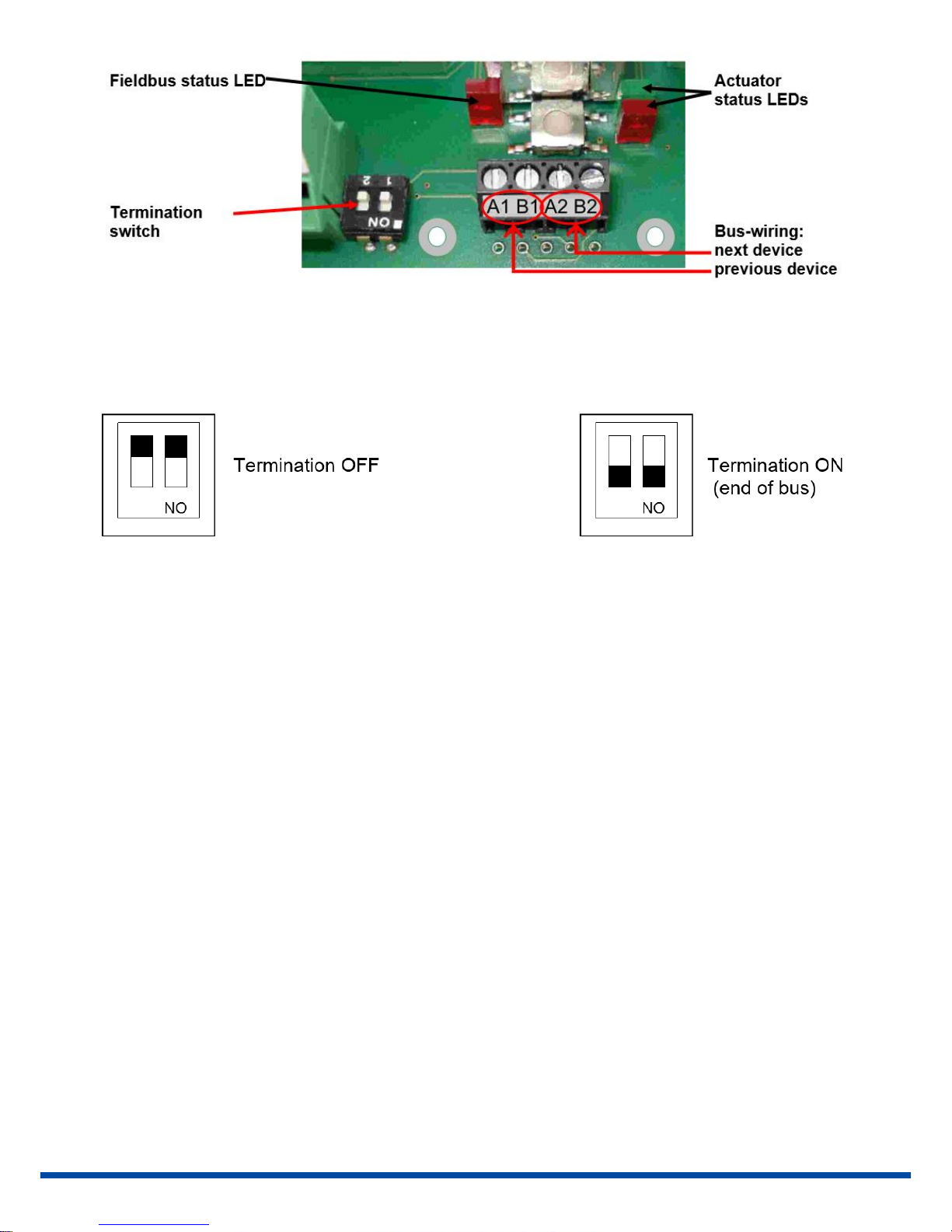
Wiring of the two Profibus cable is made to terminal blocks on the AMS main board. The two wires coming from the
previous device go to terminals A1 and B1. Wiring to a subsequent device can be done from terminals A2 and B2.
5
Figure 2 Terminal block on the main board of an actuator for Profibus DP
2.1.1. Termination
Termination of the bus is possible with the termination switch next to the terminal block, see picture 2. Both
switches have to be put to the same position mandatorily.
2.1.2. Fieldbus status LED
There is one single red LED next to the terminal block for signalling the status of the fieldbus, see picture 2.
LED Off = Mode „data exchange“
LED On = No connection to the fieldbus
2.2 Connection with Plug & Socket
At the outside of the actuator housing a socket is fitted to accept a standard Profibus plug of maker Phoenix Contact.
Appropriate type is VS-09-PROFIBUS-SC, Order No. 16 54 54 9. The two Profibus wires coming from the previous
device go to terminals A1 and B1. Wiring to the following device is made to terminals A2 and B2.
2.2.1. Termination
Termination is made inside the plug, if required.
2.2.2. Fieldbus status LED
There is one single red LED next to the terminal block for signalling the status of the fieldbus, see picture 2.
LED Off = Mode „data exchange“
LED blinking = No connection to the fieldbus

6
2.3. Slide switch for selecting the communication interface
On the main board inside the actuator there is a slide switch for selecting the
interface, see picture 3.
For normal operation, i.e. when the actuator is controlled via the fieldbus, put the
switch to lower position (red arrow).
For adjustment work, parameterisation, etc. the interface has to be put in upper
position to allow PC-communication (yellow arrow).
Caution: After finishing adjustment work, make sure that the switch is in lower
(red) position. In upper (yellow) position the interface does communicate to the
bus, but not to the actuator’s electronic!
yellow = PC-communication
red = fieldbus-communication
3. Fieldbus address
The actuator is supplied with address 0 adjusted. At commissioning the user can modify the address using the two
turn-coding switches, see picture 4. After this modification switch the actuator off for a short period and on again to
adopt the change.
Figure 4 Turn coding switches for adjusting the fieldbus address
Figure 3 Slide switch for selecting the interface

7
Adjustment of addresses 0 to 125 is possible as per the table below.
S302
S301
Profibus-
address
S302
S301
Profibus-
address
S302
S301
Profibus-
address
0 0 0 2 A
42 5 4 84
0 1 1 2 B 43 5 5 85 0 2 2 2 C
44 5 6 86
0 3 3 2 D 45
5 7
87
0 4 4 2 E 46
5 8
88
0 5 5 2 F 47
5 9
89
0 6 6 3 0 48
5 A
90
0 7 7 3 1 49
5 B
91
0 8 8 3 2 50
5 C
92
0 9 9 3 3 51
5 D
93
0 A 10
3 4
52
5 E
94
0 B 11
3 5
53
5 F
95
0 C 12
3 6
54
6 0
96
0 D 13
3 7
55
6 1
97
0 E 14
3 8
56
6 2
98 0 F
15
3 9
57
6 3
99
1 0 16
3 A
58
6 4
100
1 1 17
3 B
59
6 5
101
1 2 18
3 C
60
6 6
102
1 3 19
3 D
61
6 7
103
1 4 20
3 E
62
6 8
104
1 5 21
3 F
63
6 9
105
1 6 22
4 0
64
6 A
106
1 7 23
4 1
65
6 B
107
1 8 24
4 2
66
6 C
108
1 9 25
4 3
67
6 D
109
1 A 26
4 4
68
6 E
110
1 B 27
4 5
69
6 F
111
1 C 28
4 6
70
7 0
112
1 D 29
4 7
71
7 1
113
1 E 30
4 8
72
7 2
114
1 F 31
4 9
73
7 3
115
2 0 32
4 A
74
7 4
116
2 1 33
4 B
75
7 5
117
2 2 34
4 C
76
7 6
118
2 3 35
4 D
77
7 7
119
2 4 36
4 E
78
7 8
120
2 5 37
4 F
79
7 9
121
2 6 38
5 0
80
7 A
122
2 7 39
5 1
81
7 B
123
2 8 40
5 2
82
7 C
124
2 9 41
5 3
83
7 D
125
4. Process Image
See table „Process Image AMS Profibus-DP“ in the annex
4.1. Process Image OUTPUT
The process image OUTPUT shows the details how control of the actuator (as slave) is done.
4.1.1. Byte 1 - Set Value High-Byte
Bit 7 of Byte 1 (MSB) defines the input to be in percent (MSB = 0) or in tenth of percent (MSB = 1).
4.1.2. Byte 2 - Set Value Low-Byte
Input has to be made as per MSB of Byte 1.

8
4.1.3. Byte 3 - Process Sensor High-Byte
Bit 7 of Byte 3 (MSB) defines the input to be in percent (MSB = 0) or in tenth of percent (MSB = 1).
Caution: When using an analogue process sensor, Byte 3 and Byte 4 have to be set to „0xFF“!
4.1.4. Byte 4 - Process Sensor Low-Byte
Input has to be made as per MSB of Byte 3.
Caution: When using an analogue process sensor, Byte 3 and Byte 4 have to be set to „0xFF“!
4.1.5. Byte 5 - Command
Use the command byte to read / write data from / to the memory of the actuator.
0x00 = no action
0x20 = send data for RAM
0x21 = read data from RAM
0x1D = send data for E²PROM
0x1E = read data from E²PROM
Caution: To ensure that a command is sent to the correct address with the correct data, follow this procedure when
writing to the process image:
Write 0x00 to command Byte 5
Write address (Byte 6), Data-High (Byte 7) and Data-Low (Byte 8)
Write the actual command, e.g. 0x1E
As result the command will be sent to the actuator for one time. To send another command, the command byte
0x00 has to be sent again.
Note: At reading of data, these will be available at Byte 5 and Byte 6 of the process image INPUT after 250 msec.
4.1.6. Byte 6 - Address
Address for memory access
4.1.7. Byte 7 - Data-High
High-Byte of data to be written
4.1.8. Byte 8 - Data-Low
Low-Byte of data to be written
4.2. Process Image INPUT
The process image INPUT shows the details of the feedback of the actuator (as slave).
4.2.1. Byte 1 - Actual Value High-Byte
Feedback is scaled in line with the set value, as adjusted under 4.1.1.
4.2.2. Byte 2 - Actual Value Low-Byte
Feedback is scaled in line with the set value, as adjusted under 4.1.1.
4.2.3. Byte 3 - Working Condition / Error Code of the Actuator
The below table lists the messages that can appear during operation. Messages referring to the fieldbus interface
will be covered under „5. Diagnosis“.

9
Error Nr. [dec]
Description of Status
Working condition
0 Normal operation
1
Actuator doing auto-commissioning
2
Actuator not commissioned to the valve
14
Actuator not in AUTO mode
(in conjunction with local control unit
PSC.2)
Peripheral errors
3 Set value error
4
Torque error
5
Fail Safe-action is started
6
Set value error of the process sensor
12
Position passed over
13
Position nor reached
11
Undervoltage at supply
Errors in actuator
7
Mechanical / positioning error
8
Critical / maximum temperature reached
9
Electronics error / CRC
10
Limit of wear reached
Communication
error 32
No communication to actuator possible
Note: Error Nr. 32 may be displayed twice during commissioning of the actuator to the valve: when either end
position is reached and the measured values are stored inside the actuator. During normal operation, this error
signals a malfunction if it is displayed longer than 10 sec.
4.2.4. Byte 4 - Address
Address for memory access
4.2.5. Byte 5 - Data-High
High-Byte of data to be read
4.2.6. Byte 6 - Data-Low
Low-Byte of data to be read
10
5. Diagnosis
In the case of errors, the fieldbus interface of this actuator provides specific diagnosis data. These diagnosis data
refer to the fieldbus interface only.
Error Nr.
[dec]
Description of Error
0
Reserved
1
Error at initialising RS485/232 interface
2
Error at E²PROM
3
Stack error
4
Hardware error of Fieldbus-ASIC
5
Configuration error of gateway (unknown protocol)
6
Reserved
7
RS485/RS232 transmit-buffer overflow
8
RS485/RS232 receive-buffer overflow
9
Time-out while receiving at RS485/RS232 interface
10
Transmission error of RS485/RS232 interface
11
Receiving error of RS485/RS232 interface
12
Address error of RS485/RS232 interface
13
Configuration error by Profibus-master
14
General error of RS485/RS232 interface
15
Internal error
Note: Information about operating condition and error codes are available at Byte 3 of the process image INPUT
only.
6. Technical Data
In the case of errors, the fieldbus interface of this actuator provides specific diagnosis data. These diagnosis data
refer to the fieldbus interface only.
Communication protocol
Profibus DP (DPV0, DPV1,
Publisher Support of DPV2)
Fieldbus baud rate
up to 12 MBaud (Autodetect)
Baud rate / Wire length
kbit/s
Segment length
[m]
9,6
1200 19,2
1200 45,45
1200 93,75
1200 187,5
1000 500
400 1500
200
3000
100
6000
100
12000
100
Cycle time for data refresh
250 ms
Cycle time for data transfer
250 ms
Process image OUTPUT
8 Byte
Process image INPUT
6 Byte

11
7. GSD-File
The GSD-file is the device data sheet describing the Profibus DP slave in detail. Use the file “Configuration File
ProfibusDP V1.3” as provided on our homepage www.ps-automation.com in the section „Downloads“ under „ More
Downloads“.
8. Parameter Storage Addresses
RAM-Parameter
Address
Data high
Data low
Range
Unit
Description
000
x x 0...1000
% / ‰
present digital set value
001
x x 0...1023
digit
present set value
002
x x 0...1023
digit
present feedback
005
x x 0...1000
% / ‰
present digital feedback
Diagnosis data
185
x x 0...65536
starts x 50
Number of motor starts
186
x x 0...65536
starts
Number of motor starts at
excess temperature
187
x x 0...65536
h x 2
Operation time of actuator
188
x x 0...65536
min x 6
Operation time of motor
189
x x 0...65536
min
Operation time of motor at
excess temperature
Basically all data are accessible that are displayed in the communication software PSCS. The required addresses are
available on request.
Note: The current layout does not allow writing parameters to the actuator via the fieldbus.
9. Simulation of Profibus-environment
PS Automation provides a simulation software PSAMS1xProfibusSim_V2_0 for the Profibus-DP-master simulator
BW1131 made by Bihl & Widemann.
1.) Start PSAMS1xProfibusSim_V2_0.exe on the PC
2.) Adjust communication port and Profibus address
3.) Push the button "Open Profibus-DP" in the software
4.) Enter a set value in the range of 0...100%; pushing the button "Write Profibus-DP" will drive the actuator
5.) After testing press the button "Close Profibus-DP"
6.) Disconnect power from the actuator
10. Hints for Programming
To transmit consistent date of a length of 3 or more than 4 bytes in S7 / CPU 315-2, the SFC-calls (SFC14/15) have to
be applied. The maximum number of consistent data is depending on the CPU used. Please refer to the respective
manuals for CPU-data.

12
PS Automation GmbH
Gesellschaft für Antriebstechnik
Philipp-Krämer-Ring 13
D-67098 Bad Dürkheim
Tel.: +49 (0) 6322 94980-0
E-Mail: info@ps-automation.com
www.ps-automation.com
Hong Kong
MaxAuto Company Ltd.
Room 2008, 20/F., CCT Telecom Building
11 Wo Shing Street
Fotan, Shatin, Hong Kong
Phone: <+852> 26 87-50 00
Fax: <+852> 81 01-37 43
E-mail: info@maxonic.com.hk
www.maxonicauto.com
China
Shenzhen Maxonic Automation
Control Co., Ltd.
Maxonic Automation Control Mansion
No. 3 Lang Shan Road, Hi-Tech Industrial Park,
Shenzhen, Guangdong, PRC.
518057
Phone: <+86> 755 86 25 03 88
Fax: <+86> 755 86 25 03 74
E-mail: cg@maxonic.com.cn
www.maxonicauto.com
India
PS Automation India Pvt Ltd.
Srv. No. 25/1, Narhe Industrial Area,
A.P. Narhegaon, Tal. Haveli, Dist.
IND-411041 Pune
Phone: <+ 91> 20 25 47 39 66
Fax : <+ 91> 20 25 47 39 66
E-mail: sales@ps-automation.in
www.ps-automation.in
Great Britain
IMTEX Controls Ltd.
Unit 5A, Valley Industries,
Hadlow Road
GB-Tonbridge, Kent TN11 0AH
Phone: <+44> (0) 17 32-85 03 60
Fax: <+44> (0) 17 32-85 21 33
E-mail: sales@imtex-controls.com
www.imtex-controls.com
Italy
PS Automazione S.r.l.
Via Pennella, 94
I-38057 Pergine Valsugana (TN)
Phone: <+39> 04 61-53 43 67
Fax: <+39> 04 61-50 48 62
E-mail: info@ps-automazione.it
Spain
Sertemo, S.L.
Pol. Ind. Alba - Avda. Generalitat 15
Apartado de Correos, 142
E-43480 Vila-Seca (Tarragona)
Phone: <+34> 9 77 39 11 09
Fax : <+34> 9 77 39 44 80
E-mail: hans@sertemo.com
www.sertemo.com

Annex: Process Image Profibus-DP in PS-AMS
 Loading...