

Page 1

Network Digital Video Recorder
H.264
User manual
Please read instructions thoroughly before operation and retail it
for future reference.
V0.3
Page 2

Notes:
! Do not place objects on this device!
! Do not let any solid or liquid enter the DVR!
! Clean the circuit board, connectors, fans and case with a brush regularly
but remember to turn off the power and pull the plug before cleaning .
! Do not disassemble, maintain the device, or replace parts by yourself.
! Avoid knocking this DVR. Do not drop the device.
Operational Environment
! Place and use the product at a temperature of 0
℃
~ 40
℃
. Avoid direct
sunlight and be away from heat sources.
! Do not install the device in a damp environment;
! Do not expose the device to smoky and dusty environment.
! Keep the device be installed horizontal and in a stable place. Take care to
prevent it from falling.
Page 3

Directory
1 Production Introduction
1.1 Product overview ..................................................................................................... 1
1.2 Main functions ...................................................................................................... 1
2 Open-package check and cable connections
2.1 Open-package check............................................................................................... 1
2.2 Remote control......................................................................................................... 1
3 Basic operation
3.1 Turn on...................................................................................................................... 2
3.2 System login............................................................................................................ 2
3.3 Preview..................................................................................................................... 2
3.4 Desktop shortcut menu............................................................................................ 2
3.4.1 Circulation........................................................................................................ 3
3.4.2 Color setting..................................................................................................... 3
3.4.3 E- zoom........................................................................................................... 3
3.4.4 Audio................................................................................................................ 3
3.4.5 PTZ control............................................................................................................... 3
3.4.6 Playback.......................................................................................................... 4
4 Main menu
4.1 Main menu navigation.............................................................................................. 5
4.2 Conguration management..................................................................................... 6
4.2.1 Basic conguration.......................................................................................... 6
4.2.2 Live conguration............................................................................................ 7
4.2.3 Video conguration.......................................................................................... 8
4.2.4 Video program................................................................................................. 12
4.2.5 Alarm................................................................................................................ 13
4.2.6 Network............................................................................................................ 16
4.2.7 User management.......................................................................................... 19
4.2.8 P.T.Z ................................................................................................................ 20
4.2.9 Advanced conguration.................................................................................. 23
4.3 Data retrieval............................................................................................................ 23
4.3.1Time search...................................................................................................... 23
4.3.2 Event search................................................................................................... 24
4.3.3 File management ............................................................................................ 24
4.3.4 Image............................................................................................................... 24
4.4 Info............................................................................................................................ 25
4.5 View Infor.................................................................................................................. 26
4.5.1 System Info..................................................................................................... 27
4.5.2 Event Info........................................................................................................ 27
4.5.3 System log..................................................................................................... . 27
4.5.4 Network state................................................................................................. 28
4.5.5 Online users................................................................................................... 28
4.6 Disk management................................................................................................... 28
Page 4

4.7 upgrade maintenance............................................................................................. 28
4.8 Logout..................................................................................................................... 29
4.9 System shutdown.................................................................................................... 29
5 Remote monitoring
5.1 Access..................................................................................................................... 29
5.1.1 LAN................................................................................................................ 29
5.1.2WAN................................................................................................................ 31
5.2 Remote eld preview.............................................................................................. 32
Appendix 1. FAQ
.......................................................................................................
33
Appendix 2. Hard disk capability calculation
............................................... 38
Page 5

1
1 Production Introduction
1.1 Product overview
The series DVR is designed specially for security and defence eld and is an outstanding
digital surveillance product. It introduces embedded LINUX operating system which is very
stable. It introduces standard H.264 mp video compressed format and unique temporal
and spatial filtering algorithm which insures the high quality image and low bit rate
synchronous audio and video surveillance. It introduces TCP/IP network technology which
achieves the strong network data transmission capability and remote control capability.
The series DVR can be used individually or online applied as a part of a safety surveillance
network. With the professional network video surveillance software it achieves the strong
network communication ability and telecommunication ability.
The series DVR can be applied in the bank, telecom, electric power system, judicial system,
transportation, intelligent housing, factory, storehouse, water conservancy and so on.
2 Open-package check and cable connections
2.1 Open-package check
When you receive the product, please conrm whether it is consistent with the product
model you ordered and check carefully whether there is any obvious damage of the
product. After opening the casing, check whether the connection between the internal
data wire, power wire, fan power wire and so on and the main board are rm .Please
protect the labels afxed to the oor or rear panel , which is very important to our after-
sales service work. When you contact our company for after-sales service, we need you to
provide the model and serial No. on the label.
2.2 Remote controller operation
The operating steps to control multiple DVRs by remote control:
The default device number of the DVR is zero, you can operate directly without resetting
when using the remote controller to control a single DVR.. But if you use one remote
control to operate multiple DVRs, please refer to the following steps.
Step one: Enter DVR to see the device number: [System configuration]-[Basic
conguration]-[Device Number]. The device number of different DVR can be set the same.
For easy operation, we suggest to set the device number not too large.
Step two: Activate the remote control: Aim the remote control to the DVR you will control,
press the “ADD” button, then input the device number [between 1-65535], and then press
“ENTER” to conrm.
Step three: Cancel the remote control : You can lock the DVR when you press any button
with “ADD” button, or do no action on the buttons, it will be locked after 30 seconds.
Page 6
2
3. Basic Operation
3.1 Turn on
Plug the power supply, the power indicator light will illuminate and the video recorder
turns on, you will hear a beep at this time. After startup, the default setting of the system is
multiple-screen output mode and video recording starting up automatically.
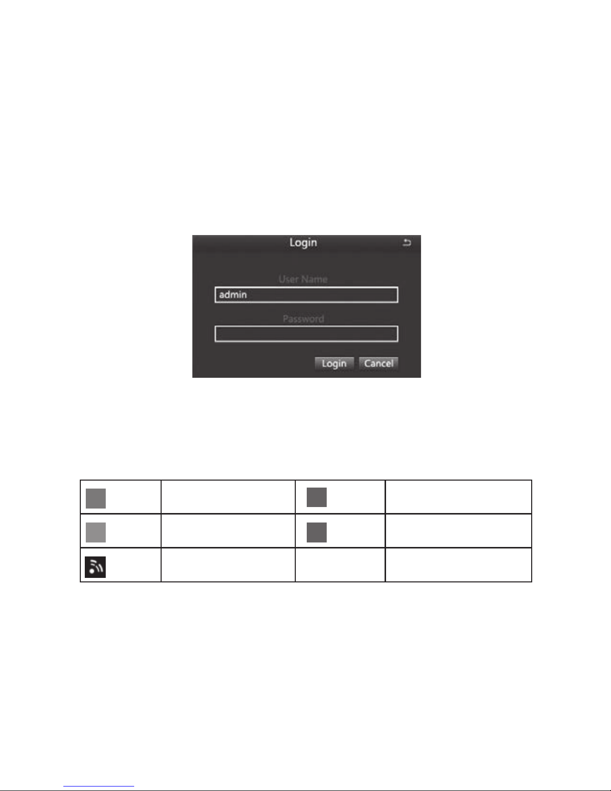
3.2 System login
When the DVR boots up, the user must login and the system provides the corresponding
functions with the user purview.
3.3 Preview
After entering the preview status , double-click the left mouse button to choose the switch
between the windows.
The system date, time and channel name are shown in each viewing window. The
surveillance video and the alarm status are shown in each window.
Table 3.1 Preview page icon
3.4 Desktop shortcut menu
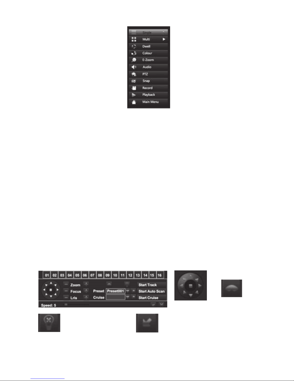
In preview mode you can right click mouse to get a desktop shortcut menu and right
click mouse again to ESC the desktop shortcut menu.
Manual recording or
Trigger recording
Motion detection
recording
Network disconnection
(Green)
(Yellow)
(Red)
(Blue)
Alarm recording
Timing recording
Page 7
3
Picture 3.2 Shortcut Menu
3.4.1 Start Scan
Start Scan means the system will show each live picture in order automatically according
to the order of the video devices in the channel grouping.
Only when the user selects the channel grouping under the display mode[main
menu]>[conguration management]>[live], and it can not show all channels completely
under the current preview, this button is available.
3.4.2 Colour
Set image parameters for all channels. The image parameters include: brightness,
contrast, saturation and hue.
3.4.3 E -Zoom
E-Zoom for big picture of single channel
3.4.4 Audio
Set startup, turn-off and silent mode of audio for the channel, and adjust the volume ..After
select (automatic), it will start up audio of the big picture channel automatically.
3.4.5 PTZ
Control the RS485 device of all channels. It can set address, Baud rate, Protocol, Preset,
trail patrol , track and so on of the RS485 device under [Main menu]>[Configuration
Management]>[PTZ].
Adjust direction
of the PTZ.
Wiper control.
Control the external infrared devices. Function hidden bar, right-click to cancel hidden.
Page 8
4
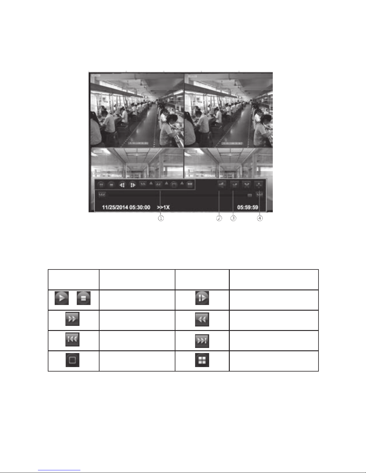
3.4.6 Playback
Play the video les in the hard disk. You can also search the video according to time and
event under [main menu] →[data retrieval] to enter the playback interface.
(1)Playback control (2)Channel audio switch (3)function Hidden key (4)Operate playback
Playback control details as follow:
Table 3.2 Playback control key
Note: Frame by frame play back is achieved using the pause function.
Function
Play/Pause
Fast motion play
Play previous le
Single-screen display
Function
Play according to frame
Playback
Play next le
Multi-screen display
Button
Button
Page 9

5
4 Main menu
4.1 Main menu navigation
Set the system time, date format, time format, language, the
device number, video format, standby time, daylight saving time
Set the channel name, output mode, block area of each channel,
etc
Start up video recording , set up the video stream, position of
channel name, video circulation, snapshot, etc
Set timer recording, motion alarm recording, period of sensor
alarm recording
Set sensor alarm of each channel, motion detection, video loss,
other alarms, alarm output, etc
Set basic network parameters, and set network sub-stream,
email, WIFI and Dynamic Domain Name Service
Modify users, change passwords, add users and delete users
Set the PTZ address, baud rate, protocol, preset, cruise , track, etc.
Restore the factory settings, import and export the device
parameters
Search specied period of time recording , playback the video of
this period
Search motion detection, sensor alarm and all videos, play back
the video of this period
Inquiry and export of motion detection, video loss, sensor alarm
and other events
Search equipment operation log according to time, it can also be
exported
Display information of network settings and dynamic DNS
settings
Show hard disk’s total space, free space, read and write status
and to format. the hard disk
Delete and lock the video les of specied time period
Delete, lock and save the image of specied time period
Display the device name, serial number, version, release date
Display the current network users accessing the device
Upgraded with an external device ( eg: USB)
After log-off , exit system and log in
Main menu Submenu Function
Basic
conguration
Live
conguration
Recording
conguration
Recording
Plan
Alarm
conguration
Network
conguration
User
management
Advanced
conguration
Network
status
Hard disk
management
User log-off
Data retrieval
View
information
Time search
Event search
System Info
Event Info
System log
Online users
Image
P.T.Z
File management
Conguration
management
Upgrade
maintenance
System
shutdown
Page 10
6
4.2 Conguration Management
Set every function parameters for the device, including: basic configuration, live
conguration, recording conguration, recording plan, alarm conguration, network
conguration, user management, PTZ conguration, advanced conguration
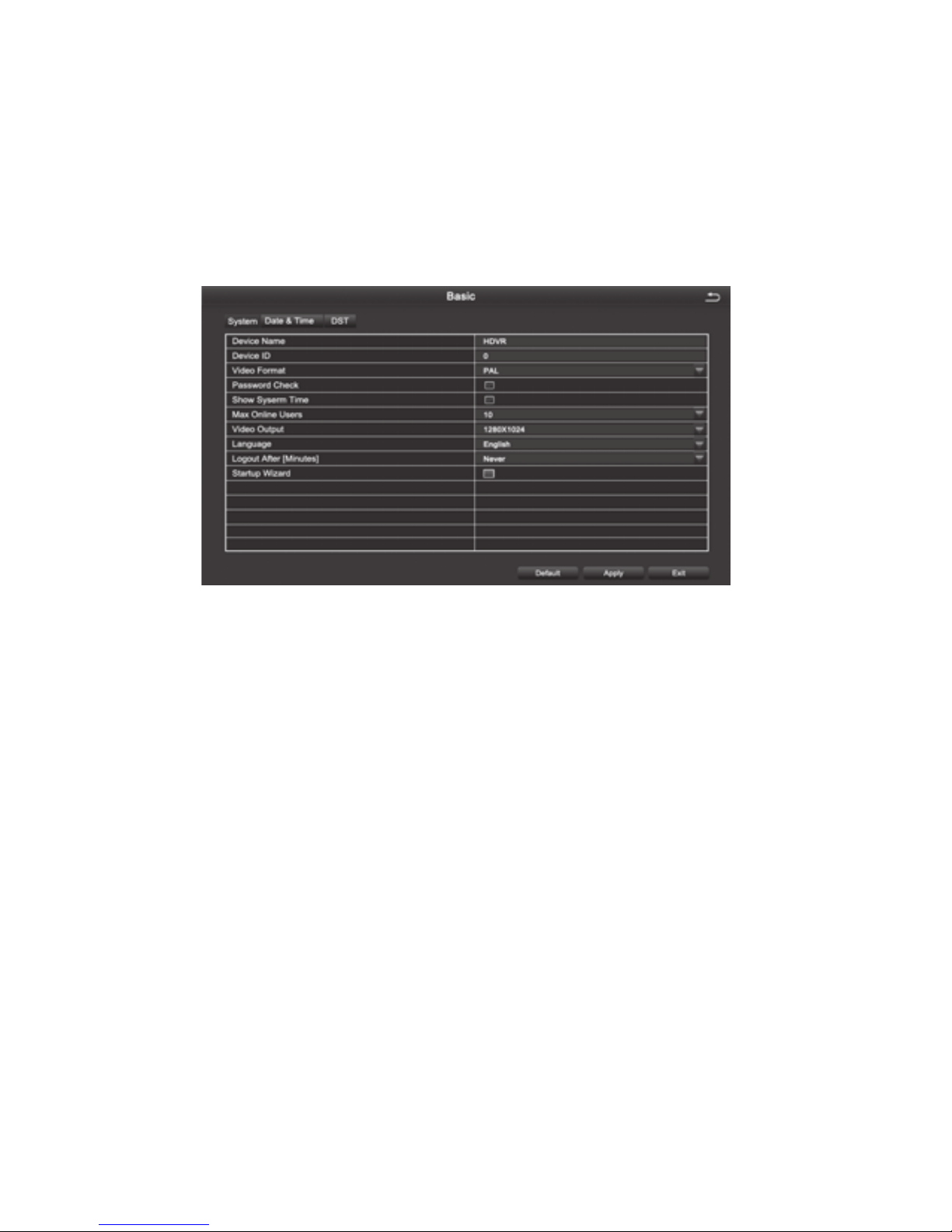
4.2.1 Basic Conguration
Basic conguration includes three sub menus: system, date and time, daylight saving time
Figure 4.10 Basic settings
1.The system
[Device Name] Client or system name displayed by IVSS
[Device ID] used when a remote control controls multiple DVR
[Video Format] Support PAL and NTSC format
[Password Check] Choosing this item means user must enter user name and password in
the system Settings, and have corresponding purview before corresponding operations
[Show System Time] Choose whether to display time in the eld or not
[Max Online Users] Set the number of network users visiting the device
[Video Output] User can select VGA 800 * 600, VGA 1024 * 768, VGA 1280 * 1024, HDMI,
etc. output mode
[Logout After (Minutes)] When there is no action exceeding the set time, the system will
automatically log out
[Startup Wizard ] Whether to display wizard or not when turn on the machine
2.Date & Time
In this interface, set the date format, time format, time zone; you can also adjust the
system time manually
Note: the default time zone of the system is GMT
You can select [Time Synchronization] to correct time. Network time server can be set
3.DST(Day Light Saving)
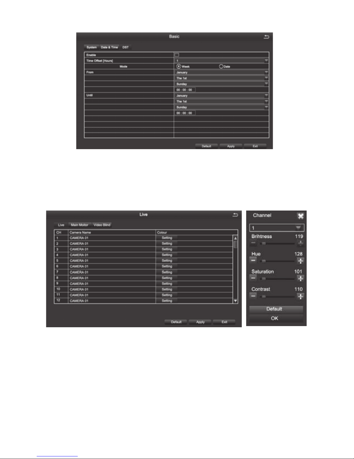
Set the start and end time of daylight saving time by week or date. As Figure 4.11,
Page 11
7
Daylight saving time setting Figure 4.11
4.2.2 Live Conguration
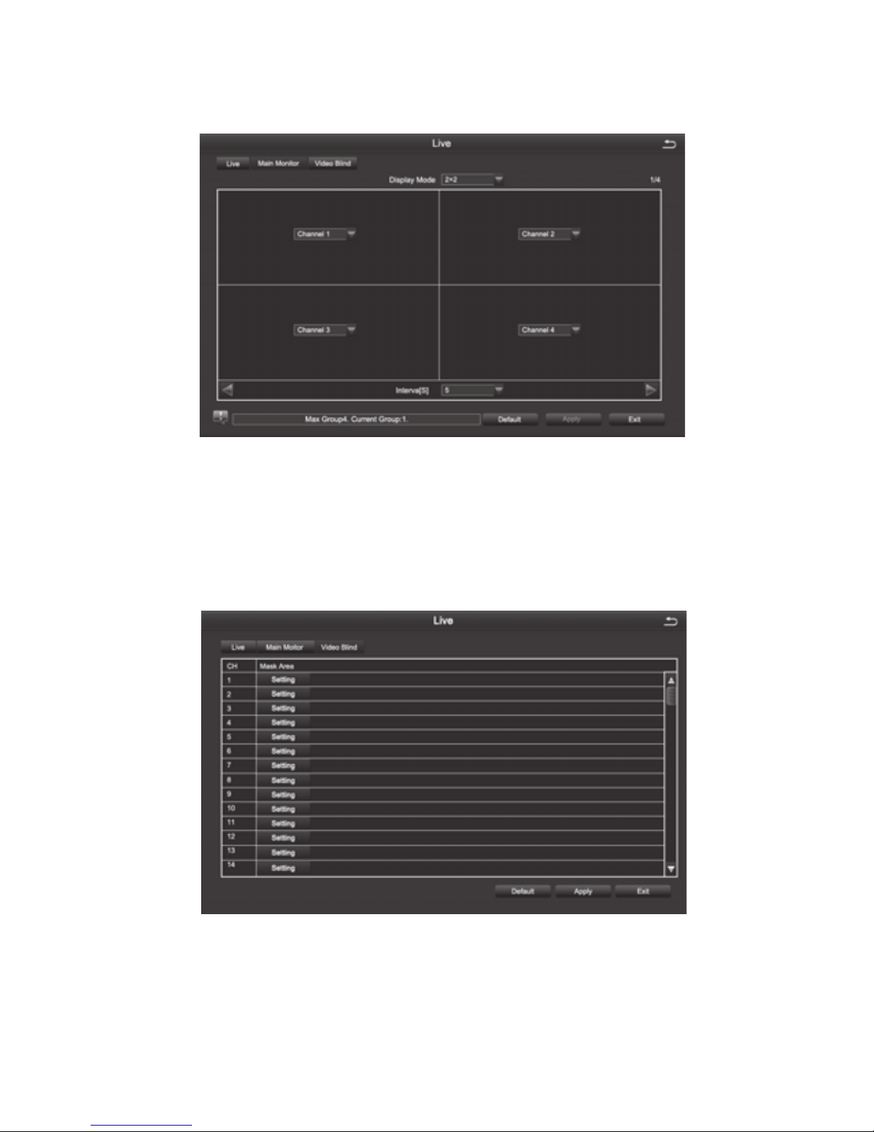
Live conguration includes three submenu: Live, Main Monitor, Video Blind.
1.Live
[Camera Name] Click channel Name, the system will pop up a soft keyboard, users can
change the channel name if necessary. Clicking the “shift “ key to switch input methods
[Colour] Users can adjust the brightness, hue, saturation, and contrast of the
corresponding channel
Page 12
8
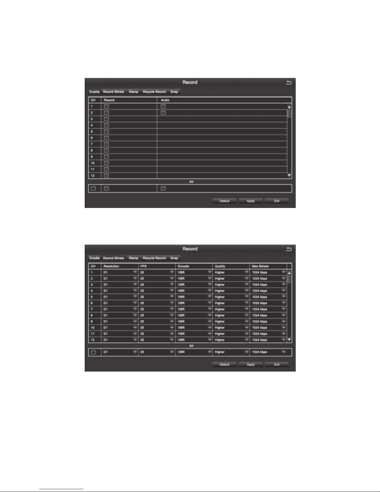
2. Main Monitor
[Interval] The time interval between one channel picture and the next one channel
3. Video Blind
Users can cover up some areas of the live picture, maximum of four areas per channel
[Setting] After entering the live picture , press and hold the left mouse button, drag the
mouse to set the blocked area , then click [apply]to save the settings; Double-click on the
area you want to delete, later changed into a black area, right-click, Exit. then click [apply]
can delete the blocked area
Page 13
9
4.2.3 Recording Conguration.
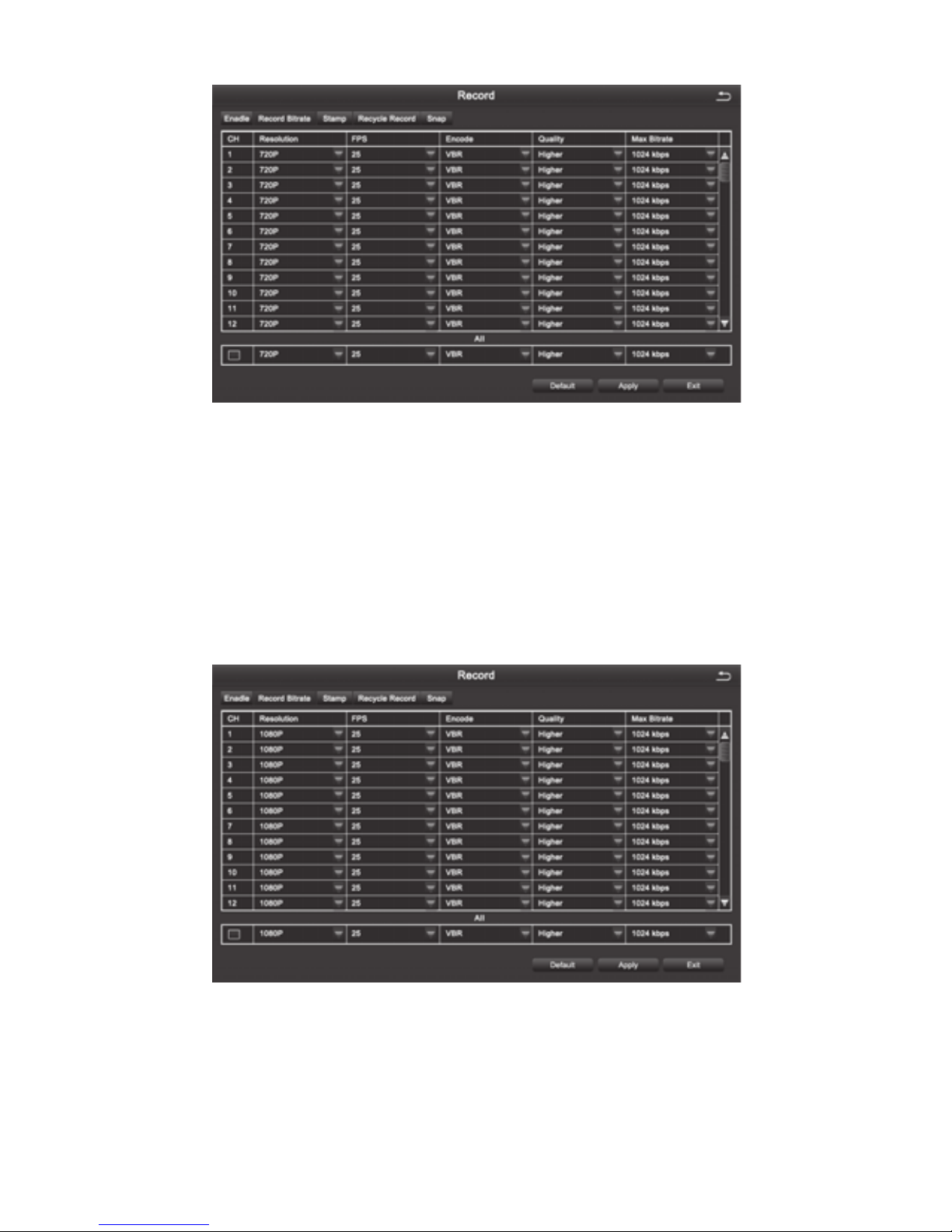
Record configuration includes six submenus: Enable,Record Bitrate,Stamp,Recycle
Record,Snap
1. Enable
2. Record Bitrate
Note: Detailed parameters, to prevail in kind.
[Resolution] 4 channel device supports 4-CH D1; 8 channel device supports 8-CH D1; 16
channel device supports 16-CH D1.
[FPS] Range of choice : 1-30[NTSC] 1-25 (PAL)
[Encode] Support VBR and CBR
[Quality] The higher the quality is, the clearer the video images are
Optional quality levels: Lowest, Lower, Low, Medium, Higher, Highest
[Max Bitrate] Range of Choice : 256kbps~2048kbps
Page 14
10
[Resolution] 4CH device supports both 4CH 720P (AHD Camera) and 4CH 960H(Analog
Camera); 8CH device supports both 8CH 720P(AHD Camera) and 8CH 960H(Analog
Camera).
[FPS] Range of choice : 1-30[NTSC] 1-25 (PAL)
[Encode] Support VBR and CBR
[Quality] The higher the quality is, the clearer the video images are
Optional quality levels: Lowest, Lower, Low, Medium, Higher, Highest
[Max Bitrate] Range of Choice : 256kbps~2048kbps
[Resolution] 4CH device supports both 4CH 1080P (AHD Camera) and 4CH 960H(Analog
Camera); 8CH device supports both 8CH 1080P(AHD Camera) and 8CH 960H(Analog
Camera).
[FPS] Range of choice : 1-30[NTSC] 1-25 (PAL)
[Encode] Support VBR and CBR
Page 15
11
[Quality] The higher the quality is, the clearer the video images are
Optional quality levels: Lowest, Lower, Low, Medium, Higher, Highest
[Max Bitrate] Range of Choice : 256kbps~2048kbps
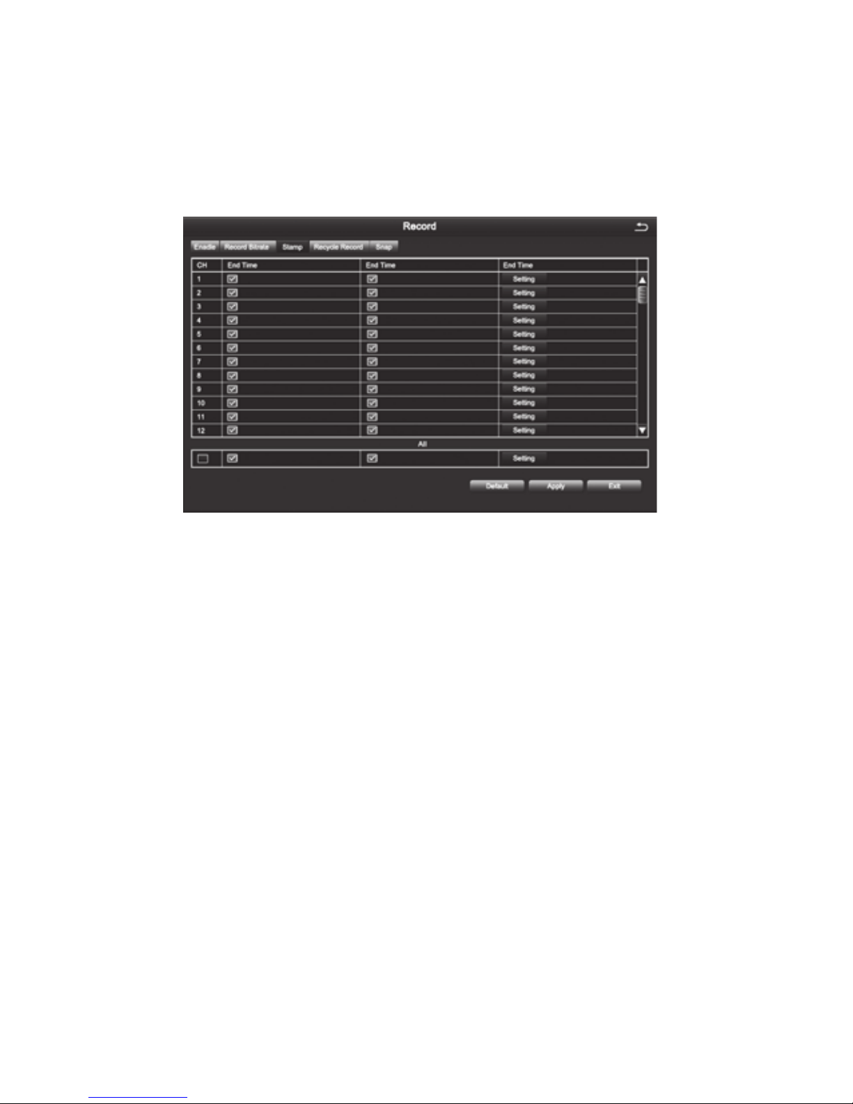
3. Stamp
[Camera Name] Choose whether to display the channel name or not
[Time Stamp] Choose whether to display time on this channel or not
[Position] After clicking this button, Users can use mouse to drag the channel name and
time stamp to any position on the live image
4. Recycle Record
After selecting this item , When the hard disk is full, it will automatically cover the earliest
les and continue recording ; Otherwise, it will automatically stop recording and prompt
"The remaining space is insufcient" on the screen
5. Snap
In this interface, the user can set the resolution, image quality level, time interval of
snapshot and the number of snapshot for one time
Page 16
12
4.2.4 Schedule
Schedule includes three submenus: timing recording, motion alarm recording, and sensor
alarm recording
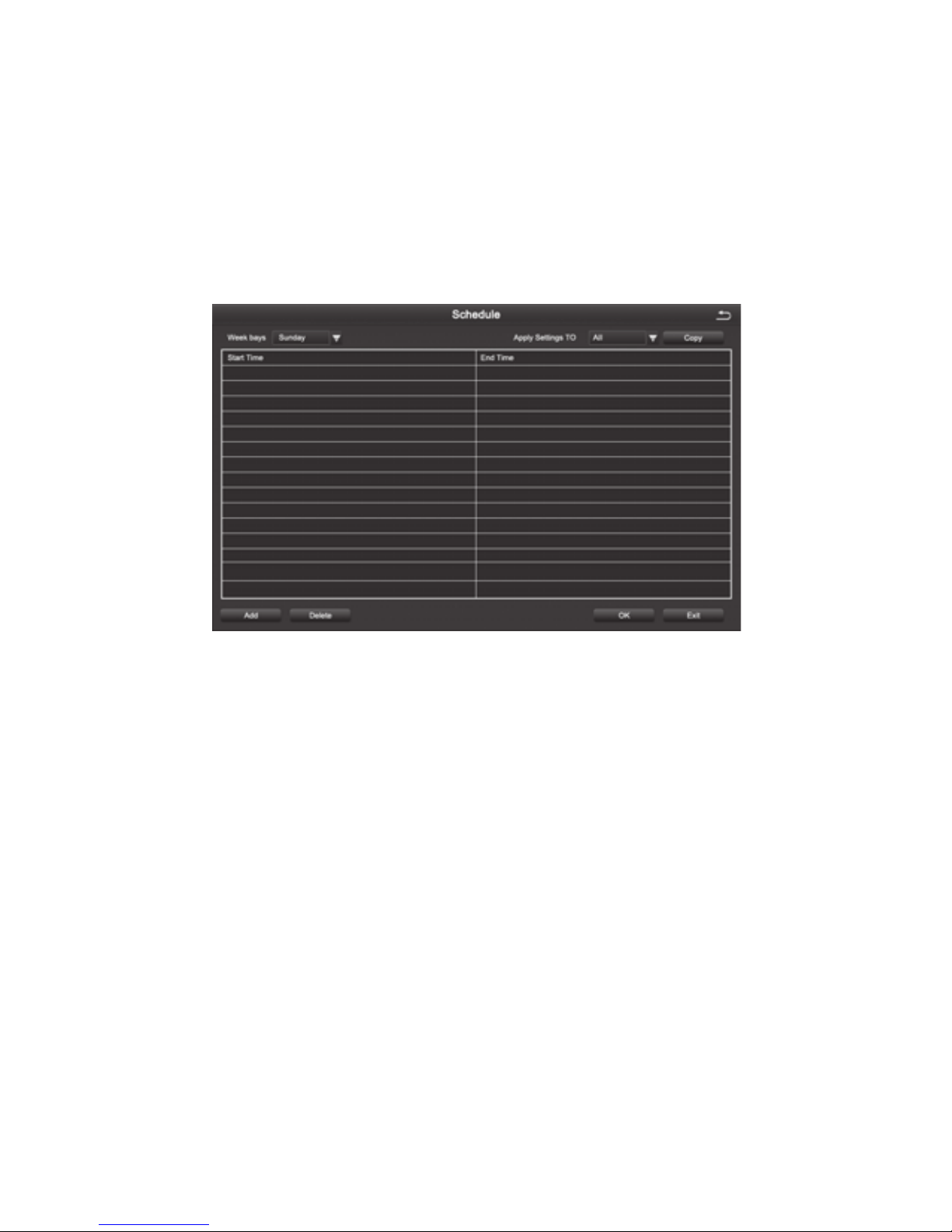
1. Timing Recording
[Copy] Apply the schedule of a channel to the other or all channels
Select the channel: Double click the left mouse button, edit the week plan, as shown in the
picture.
[Add] To add a recording schedule of some day
[Delete] To delete the selected schedule
[Copy] Copy the schedule of a specied date to another date.
2. Motion Alarm Recording
The setting method is the same to the timing recording setting, please refer to the timing
recording settings
Note: The default Schedule for Motion alarm is all selected
3. Sensor Alarm Recording
The setting method is the same to the timing recording setting, please refer to the timing
recording settings
Note: The default schedule for sensor alarm is all selected
Page 17
13
4.2.5 Alarm Conguration
Alarm conguration includes ve submenus: Sensor alarm, motion detection, video loss,
other alarm and alarm output
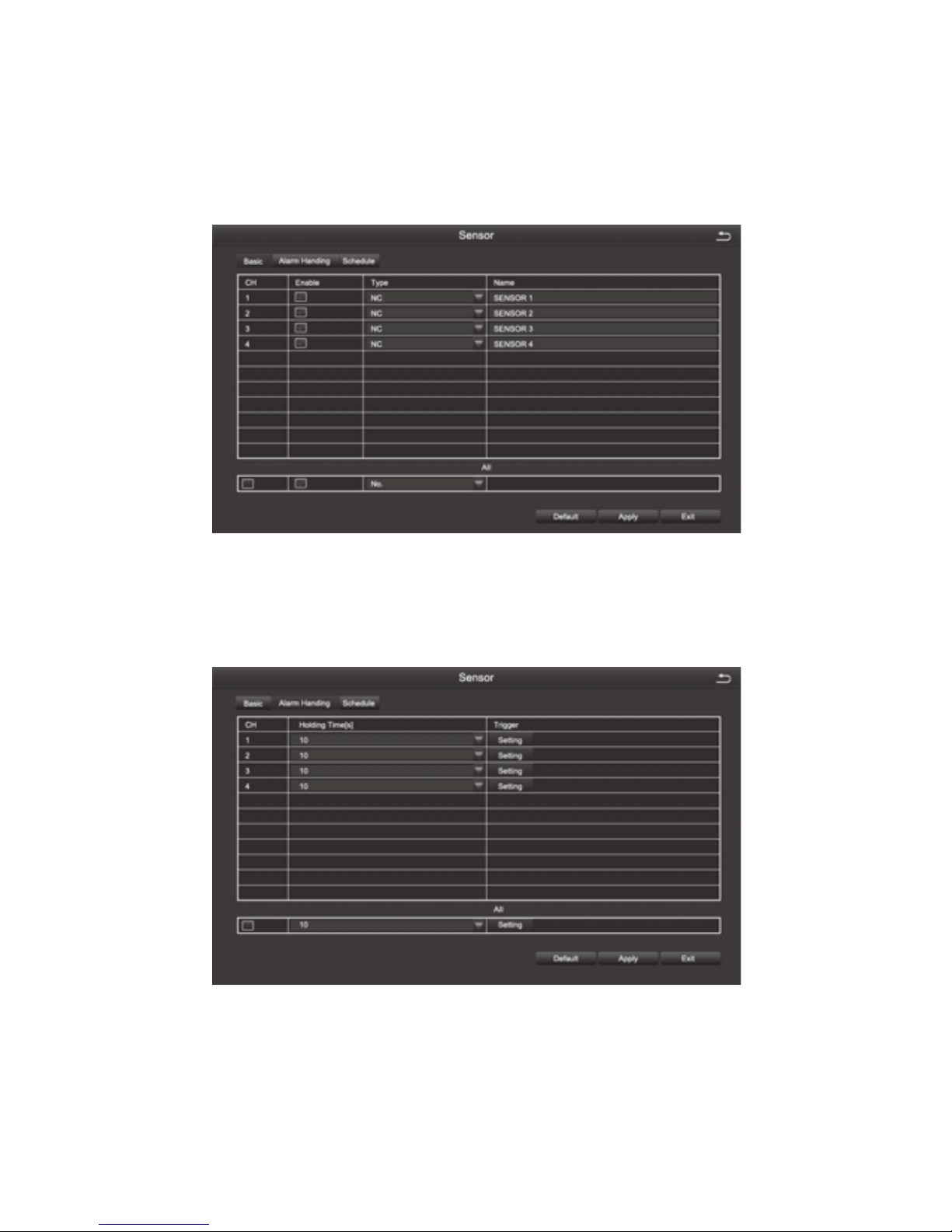
1. Sensor
1-1 Basic
[Enable] To open sensor alarm function of the corresponding channels
[Type] To choose alarm type: Normally open and normally closed
[Name] Set the alarm name.
1-2 Alarm Handling
[Holding Time] To select alarm delay time for the channel , optional time: 5 s, 10 s, 20 s, 30 s,
60 s 120 s, always
[Trigger] After clicking you can set alarm Configuration, trigger recording, PTZ
linkage, etc
Page 18
14
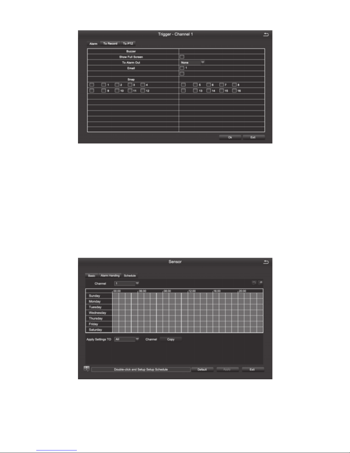
[Buzzer] After selecting the alarm, when an alarm is triggered , the buzzer will alarm
[Show Full Screen] When an alarm is triggered, the alarm channel screen will activate
[To Alarm Out] Select this item, it will trigger an alarm on the specied alarm output
[Email] When an alarm is triggered, the system will send the relevant information to the
user-specied mailbox, such as alarm event, snapshot, device name, device number, etc.
[Snap] When an alarm is triggered, the system will automatically capture the images of the
selected channel and store them to the hard disk.
[To PTZ] To set the action type and serial number of the linkage
1-3, Schedule
The method of setting the schedule of sensor alarm is the same to timing recording. For
the detailed setting steps , pls refer to 4.2.4 [Recording Schedule] [Timing Recording]
Note: The default schedule for sensor alarm is all selected
Page 19
15
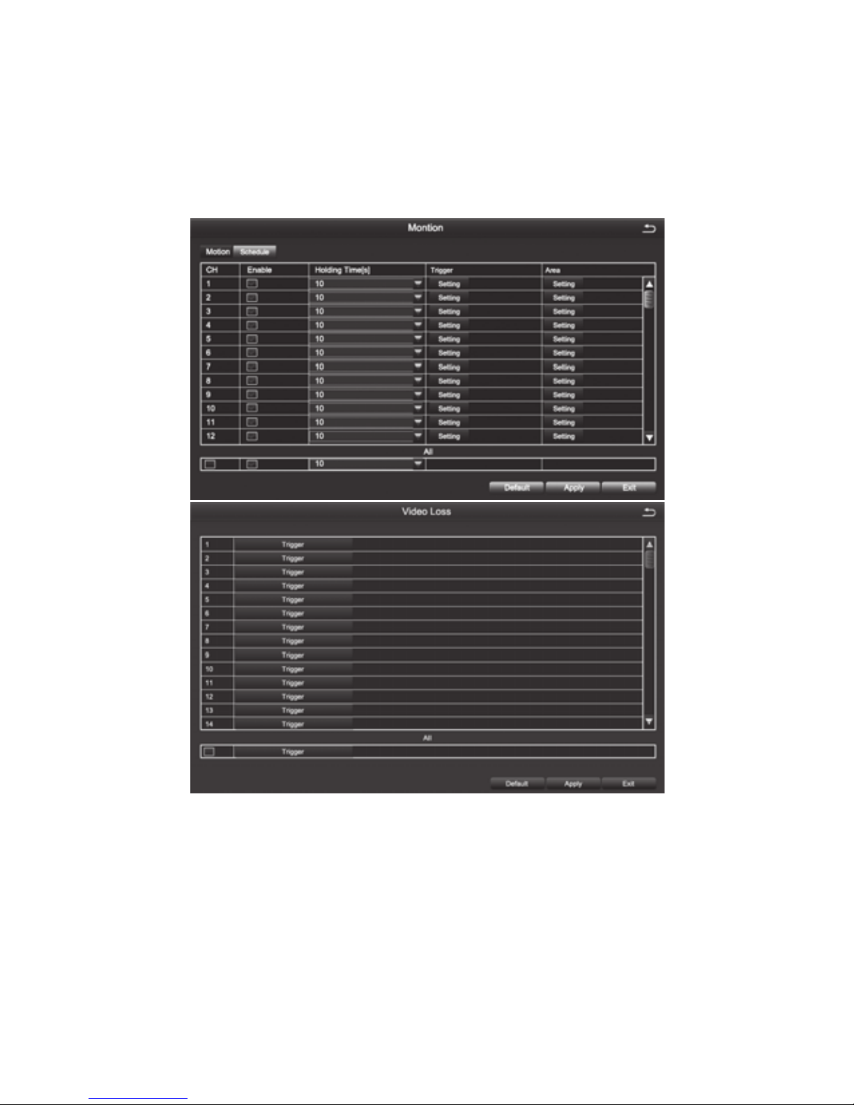
2. Motion Detection
Motion detection includes two submenus: motion detection and schedule
2-1, Motion Detection
By analyzing the video image, when the system detects a mobile signal which reaches a
preset sensitivity, motion detection alarm and the linkage function are initiated
[Enable] After selected, the motion detection function of the corresponding channel will be
opened.
[Holding Time] To select alarm delay time of the channel .Optional time:
5/10/20/30/60/120s always
[Trigger] The setting method is the same to that of sensor alarm, pls refer to 4.2.5
[Alarm Conguration], [Sensor Alarm Processing]
[Area] In this interface, the user can drag the scrollbar to adjust the sensitivity value (1-
8). The default value is 6, the smaller the value is, the higher the sensitivity is. Since the
sensitivity is affected by the color, time (day or night) and etc, so the user should adjust the
value according to the actual situation.
Page 20
16
2-2, Recording Schedule
The setting of Motion Detection Schedule is the same to that of Timing Recording, For the
detailed steps please refer to 4.2.4 - [Recording Schedule] [Timing Recording].
Note: The default schedule of motion detection is all selected
3.Video Loss
The setting of video loss alarm processing is the same to that of sensor alarm processing.
For the detailed steps, please refer to 4.2.5 [Alarm Configuration] [Sensor Alarm
Processing]
4.Other Alarm
[Alarm Type] Including hard disk full, network address conflict, disconnection, HDD
attenuation warning and disk loss
[Buzzer ] When an alarm occurs, the device will emit "didi" two long beeps
[Email] When an alarm is triggered, the system will send the relevant information to the
user-specied mailbox, such as alarm events, snapshot, device name, device number, etc.
[To Alarm Out] To select this item, it will trigger an alarm on the specied alarm output
[Disk Shortage Alarm] When the remaining capacity of the disk reaches the set value, an
alarm will be triggered
4.2.6 Network Conguration
Network Conguration includes ve submenus: Network, Sub-Stream, Email, WiFi Setup,
DDNS
Set all areas to be
detection area
Clear the set
detection areas
Exit
Drag the mouse to test
whether the sensitivity value
and the detection area are
appropriate or not
Save the settings
Page 21
17
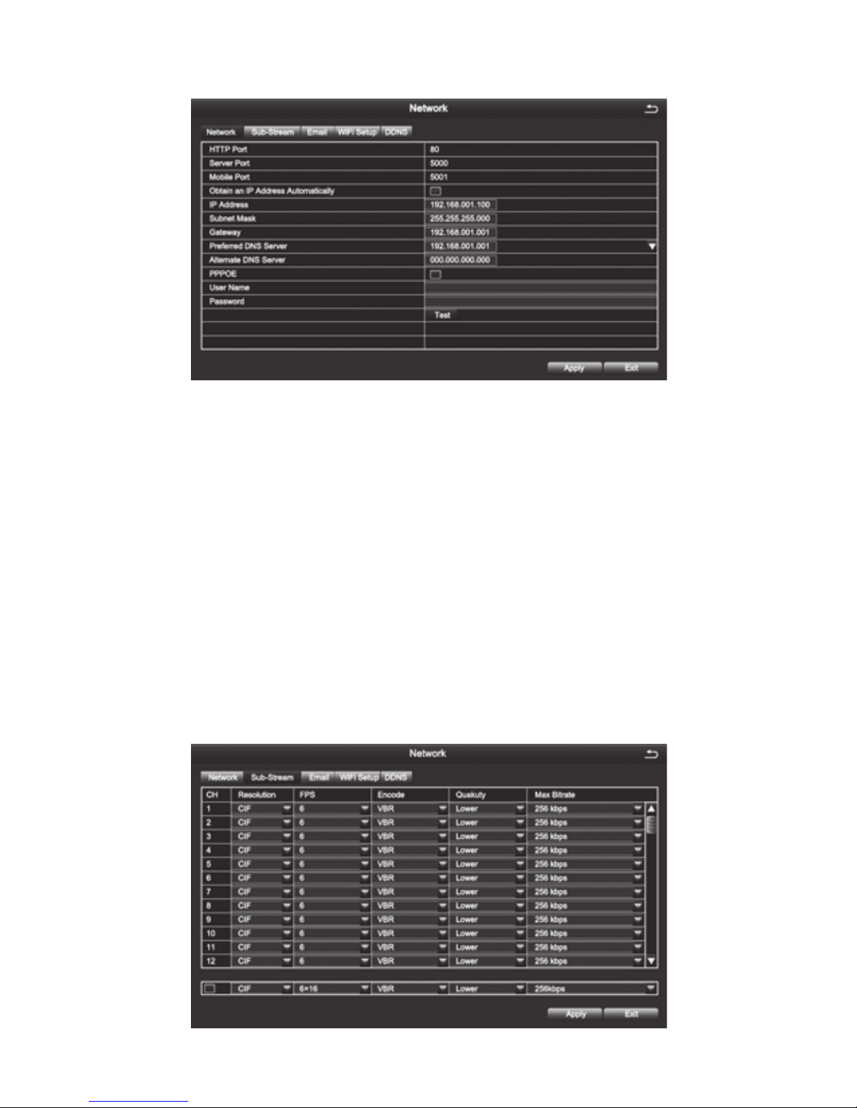
6-1 Network
[HTTP Port] Default value is 80
[Server Port] Default value is 5000
[Mobile Port] Default value is 5001
[Obtain an IP Address Automatically] To obtain the IP function automatically
[IP Address] To set the IP address of the device
[Subnet Mask] To set the subnet mask of the device
[Gateway] To set the default gateway of the device
[Preferred DNS Server] The address is provided by your network operator and must be
lled in when using mobile monitoring.
[Altemate DNS Server] The address is provided by your network operator.
[PPPOE] When enabled, the DVR will automatically establish a network connection
in the form of PPPOE, then the IP address can be seen through [Main Menu]-[View
Information]-[Network Status]
[User Name] Enter the ISP (Internet Service Provider)
[Password] The set password
[Test]Test whether the entered IP address and PPPOE information are valid or not
6-2 Sub-Stream
Page 22
18
[Resolution] Support CIF
[FPS] Range of Choice: 1-30[NTSC]1-25(PAL)
[Encode] Support VBR and CBR
[Quality] Optional: Highest, Higher, Medium, Low, Lower, Lowest
[Max Bitrate] Range of Choice: 32kbps ~ 768kbps
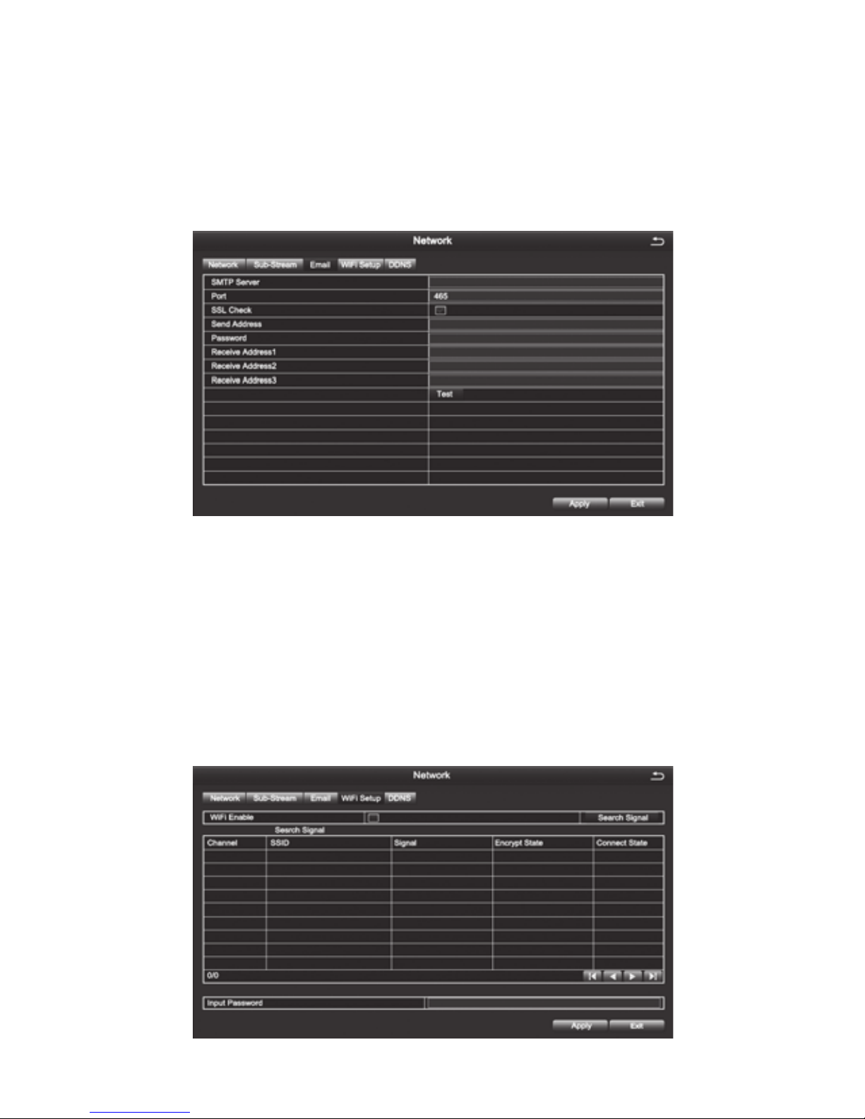
6-3 Email
[SMTP Server] Mail server address can be IP address and domain name (if it is domain
name ,it is required to confirm that the DNS setting is right ,then it can be correctly
resolved) e.g.: smtp.gmail.com
[Port] Mail server port number, the default port is 465
[SSL Check] Provide secure socket layer to login on
[Send Address] E-mail address of the mail server
[Password] The corresponding password of the Sender’s E-mail
[Receive Address] When an alarm is generated ,the system will send email to the set
mailbox , but the number of the set recipient mailbox can be no more than 3
[Test] Test whether the current mailbox conguration is successful or not.
6-4 WiFi Setup
Page 23
19
[Wi Enable] Tick this item to enable WIFI connection.
[Search Signal] Search the WIFI signal nearby after enabling WIFI.
[Input Password] Select the WIFI you have searched , enter the corresponding password;
[Setup] To set dynamic IP or static IP.
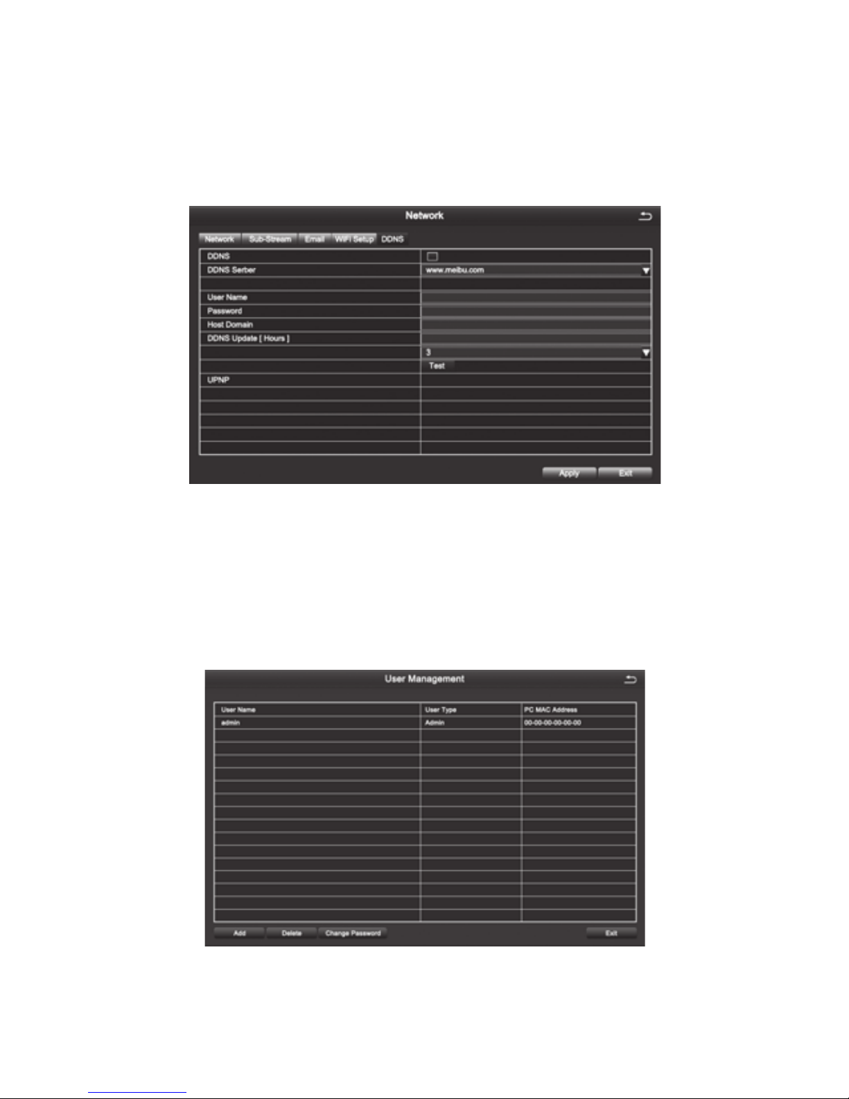
6-5 DDNS
[DDNS Server] DNS service provider URL, options are www. meibu.com and www.no-ip.
com.
[User Name] Account used when registering domain names.
[Password] The corresponding password of registered account.
[Host Domain] Domain name of the DNS server.
Save and exit, you can visit the device directly through IE.
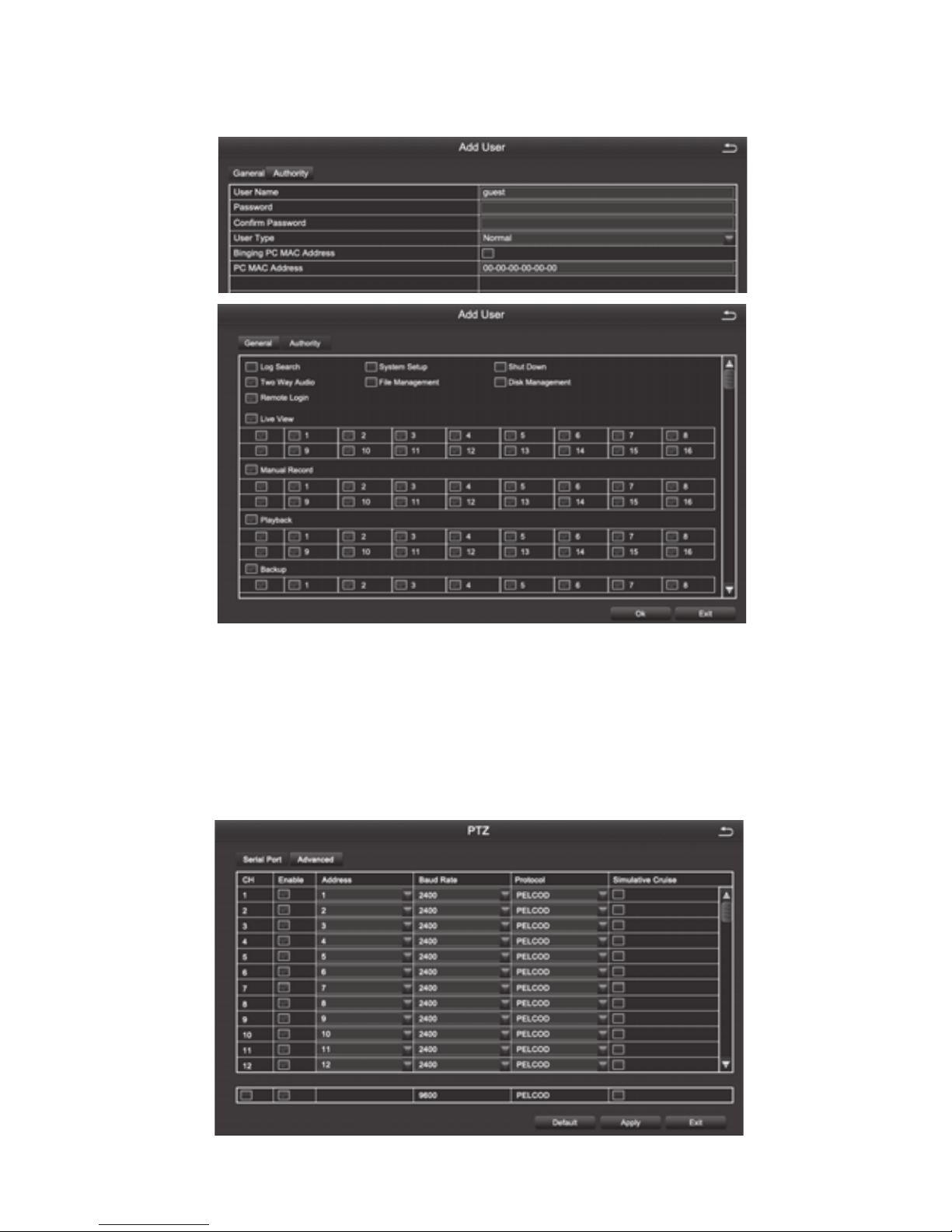
4.2.7 User Management
The default administrator name is admin, there is no password set.
Note: The length of the user name and password is no more than 32 characters
Page 24
20
[Add] Add a user name and set the user's permissions. The following dialog box appears
after clicking:
NOTE: When the computer's physical address is 0, It means that the device does
not bind to a specic computer, and user can use any computer to log on client
to remotely view the DVR; However, once setting a specic computer's physical
address, User can only log on client on the bound computer for visiting DVR.
4.2.8 PTZ
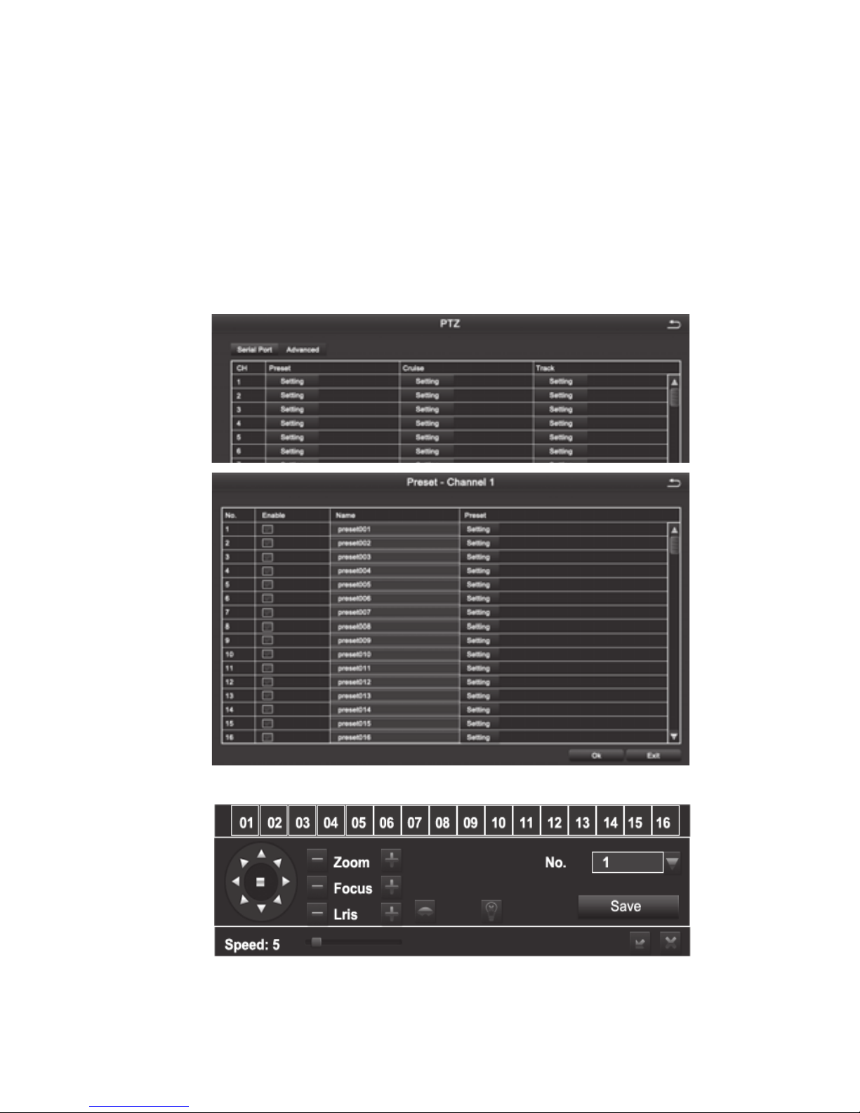
1. Serial Port
Page 25
21
[Address] Address of PTZ device
[Baud Rate] The baud rate of the PTZ device. The options are: 110,300,600,1200,2400,4
800,9600,19200,34800,57600,115200,230400,460800,921600
[Protocol] Communication Protocol of the PTZ device. The options are: PELCOP,
PELCOD, LILIN, MINKING, NEON, STAR, VIDO, DSCP, VISCA, SAMSUNG, RM110, HY,
N-control
[Simulative Cruise] After ticking and adding preset points in the cruise line conguration,
,it can achieve preset cruise regardless of whether the device supports PTZ cruise line
function or not.
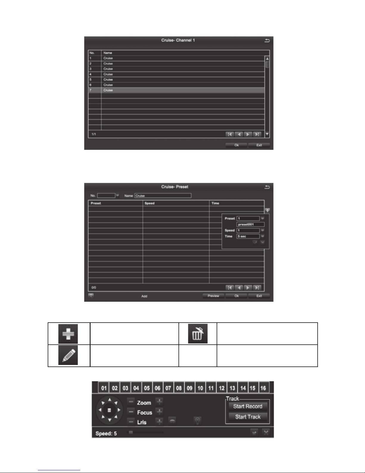
2. Advanced
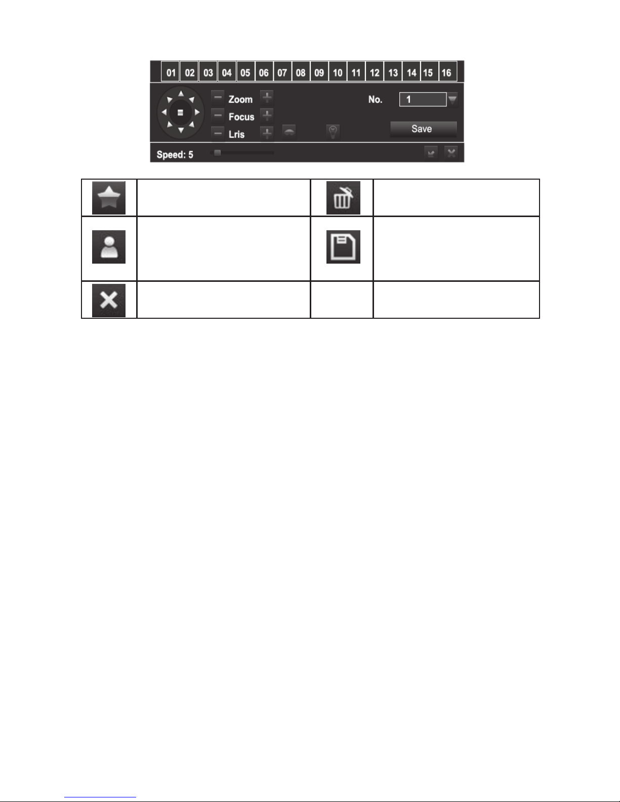
[Preset] Click [Setting] button, pop up the window as picture below.
Users can adjust PTZ to the appropriate location through toolbar button. Click [Save]and
the preset points are setting successfully. You can set maximum 128 preset points
[Cruise ] Click [Setting] button, pop up the window as picture below:
Page 26
22
[Add] Add cruise lines (can add maximum eight cruise lines);
[Setup] Selecting a cruise line and clicking this button, the interface of adding preset points
will appear, as picture below:
Icon Denition:
[Track ]
Add preset point
Modify the selected
preset point
Delete the preset point
Page 27
23
[Start Recording] By controlling the PTZ up, upper left, down, lower right, left, lower left ,
right, upper right, or stop recording track of PTZ.
[Start Track] To execute the recorded tracks.
Note: Each channel can record only one track, and auto-save after recording is completed.
When you call the track, you can directly select the channel to start track.
4.2.9 Advanced Conguration
Advanced setting includes two submenus: Reset, Import/Export
[Reset] Reset all settings to the factory settings status.
[Import/Export] (1)Through “Import/Export”, you can export the parameters to other
devices directly. There is no need to recongure other devices.
(2)The system language can be changed by import language les.
4.3 Data Retrieval
Mainly includes Time Search, Event Search, File Management and Image.
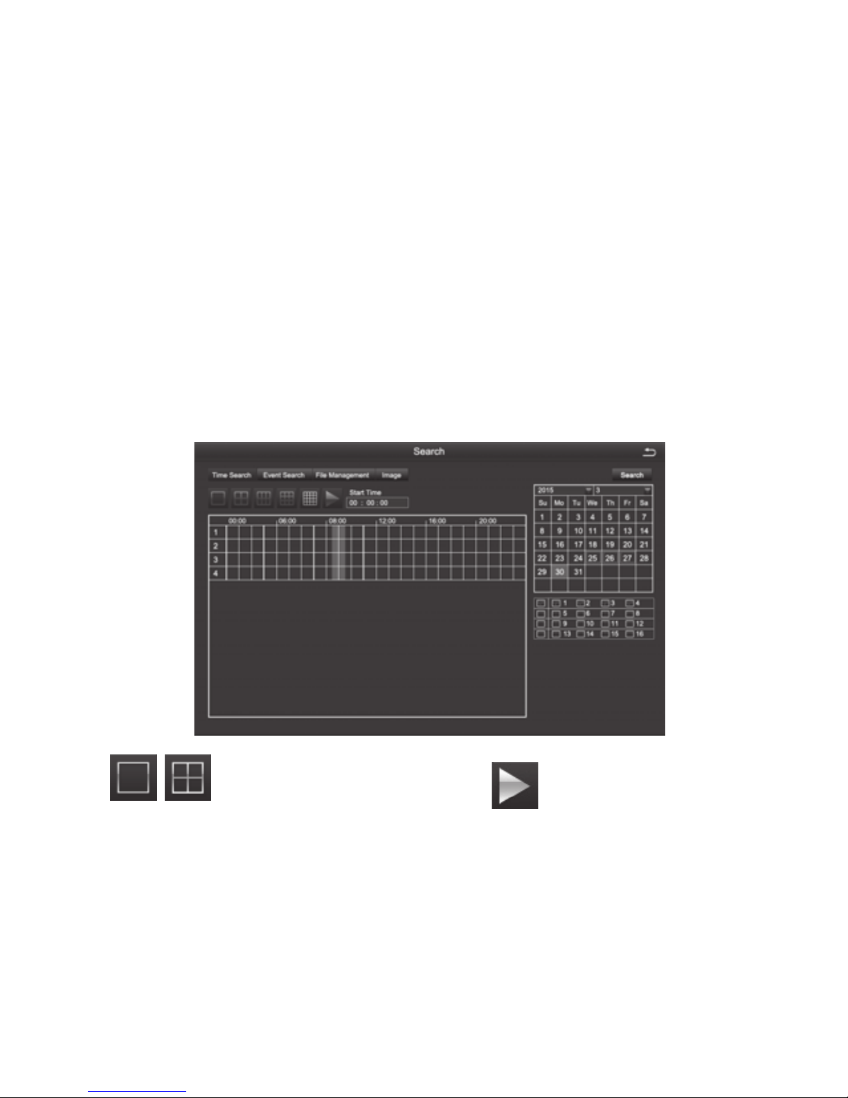
4.3.1 Time Search
Select the channel Start playing
[Search] Search the video le of set channel and time, then click the play button to start
playback.
Note: The highlighted date in the calendar indicates there is video le on that day .
Page 28
24
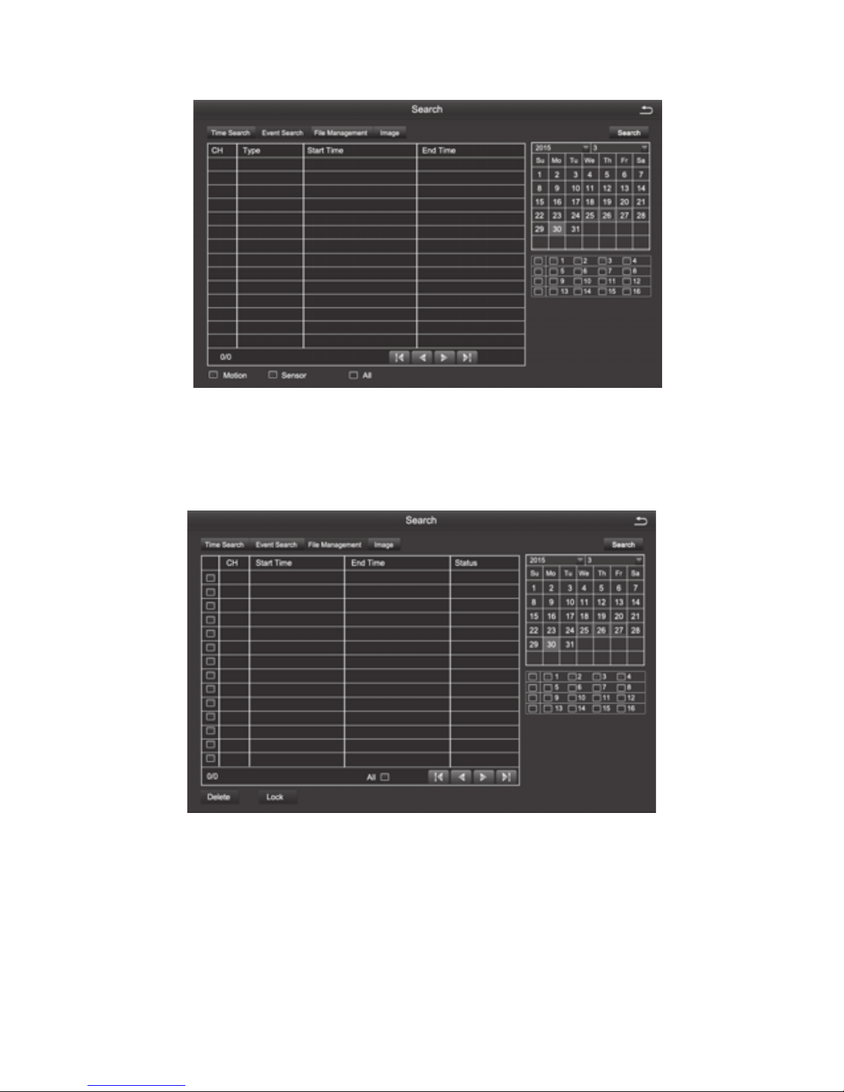
4.3.2 Event Search
[Search] Search the video le of set channel and time, after selecting the le, double click
to start playback.
4.3.3 File Management
[Search] To search the video le of set channel and time
[Lock] When the le is locked ,it can not be deleted or overwritten, but can be deleted
when formatting the disk
[Unlock] To unlock the selected le
[Delete] To delete the selected les
[All] When tick this item, you can do operation of lock, unlock, and deletion to all the les
you have searched.
Page 29
25
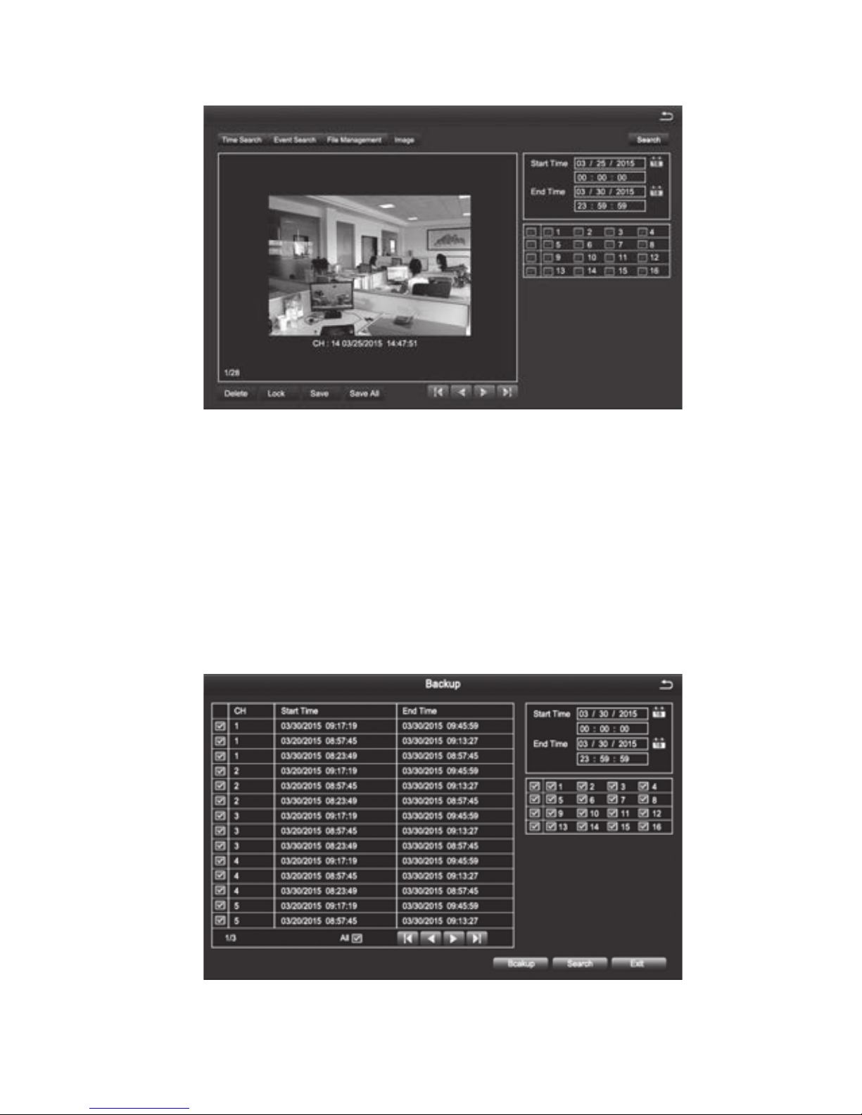
4.3.4 Image
[Search] To search the image le of set channel and time.
[Delete] To delete the currently displayed image.
[Lock] Lock the currently displayed image so that it can not be deleted or overwritten, but it
can be deleted when formatting the disk.
[Save] Save the currently displayed image to a removable storage device.
[Save All] Save all the captured images to a removable storage device.
Note: 1. The default number of storage image is 2000. If it is more than 2000, the
system will automatically overwrite the previously unlocked images.
2. Double-click the image, you can playback the video from the time when the
image was captured.
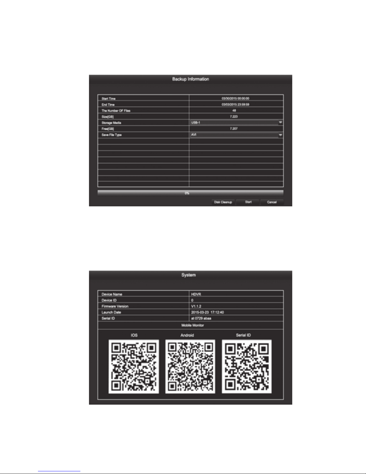
4.4 Backup
By setting, you can backup the video le to the external storage device
Note: You need to install the storage device capable of accommodating the storage
Page 30
26
les before backuping the les.
[Search] To select the les that need backup according to time and channel.
[Backup] Select les in the list and click “backup”, then it will popup a dialog box of backup
information, as shown in gure:
Disk cleanup: to delete all les in the external storage device.
4.5 View Information
Including five submenus: system information, event information, system log, network
status, and online users and other relevant information
4.5.1 System
To display the basic information about this device, including hardware information, software
version number, release date, and phone port number .
Page 31
27
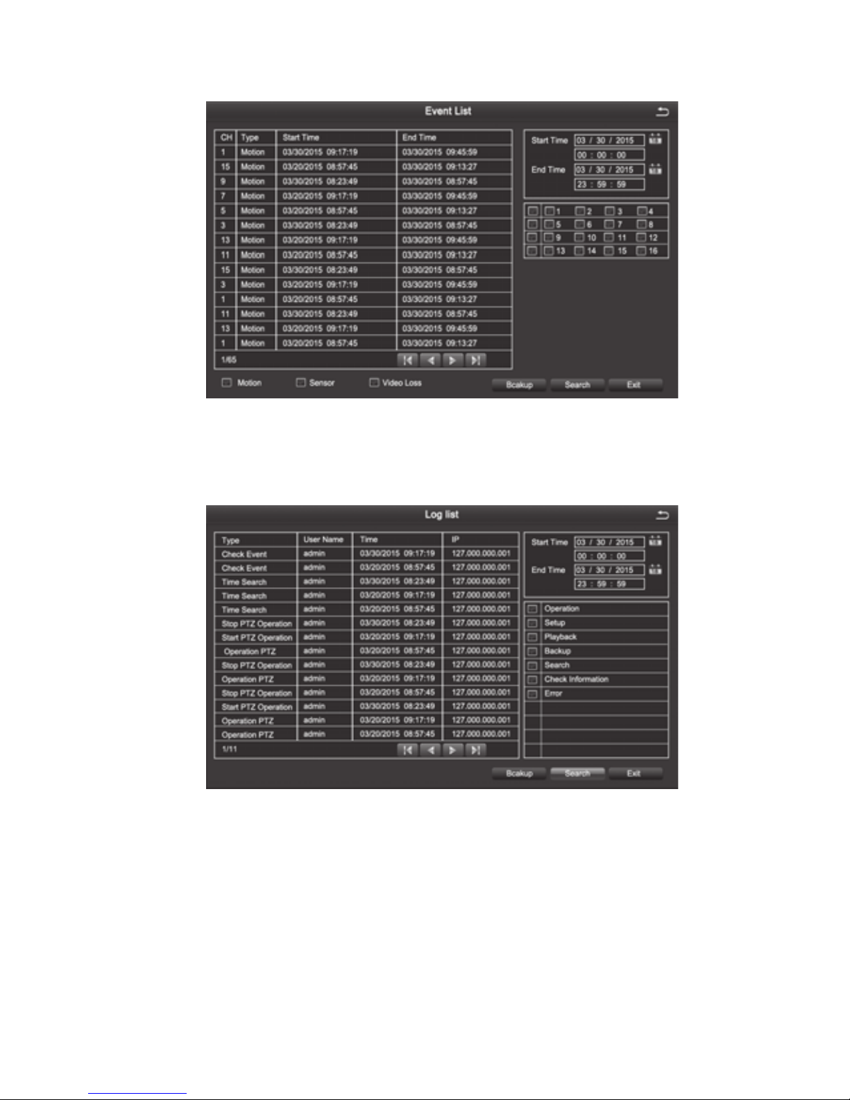
4.5.2 Event list
Users can select the event information of motion detection alarm, sensor alarm, video loss
alarm and so on which users need to inquire about according to time and channel.
4.5.3 Log list
Users can search the operation information of the login user based on time and the
operation type. After formatting the hard disk, the information will be cleared.
Page 32
28
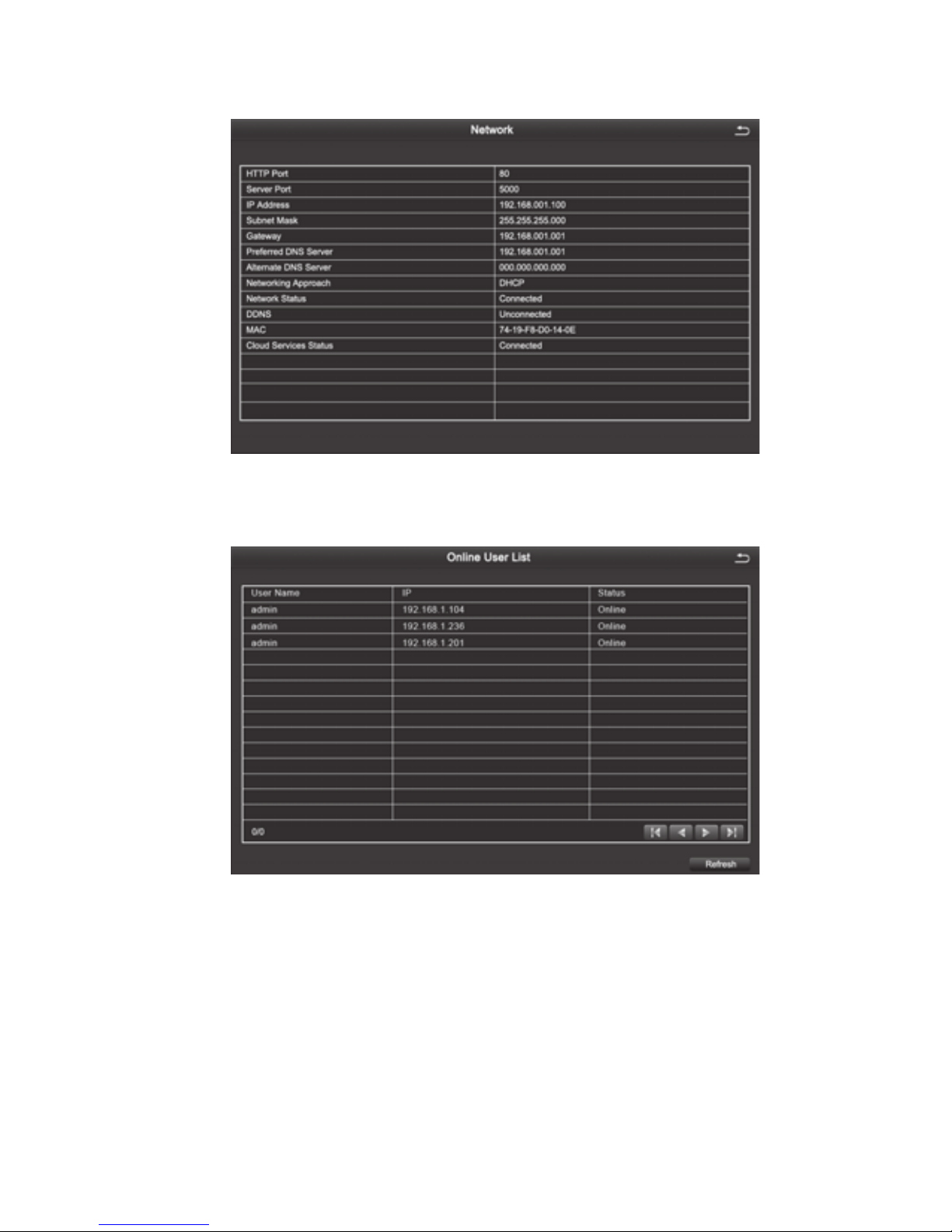
4.5.4 Network
Users can view the related parameters of the network settings.
4.5.5 Online Users list
See the network user information connecting the local DVR.
4.6 Disk Management
[Refresh] To re-check the disk that can be indentied.
[Browse] To check the information of the selected hard disk, including hard disk capacity,
free space, hard disk status, properties, the total number of pictures that can be stored,
stored number of pictures.
[Format] To delete the data on the selected hard disk, including locked les and images.
4.7 Upgrade Maintenance
[Refresh] To check the removable storage devices that can be indentied.
Page 33
29
[Upgrade] Click this button after selecting the upgrade le on mobile storage device, then
the system will start upgrading. The upgrade process takes about 5 minutes.
4.8 Log User off
The system will exit the current logged-on user.
4.9 System Shutdown
To save the data and exit system.
5 Remote Monitoring
5.1Remote Access
Remote Access to DVR needs the Ethernet, usually using LAN and Internet.
5.1.1 LAN
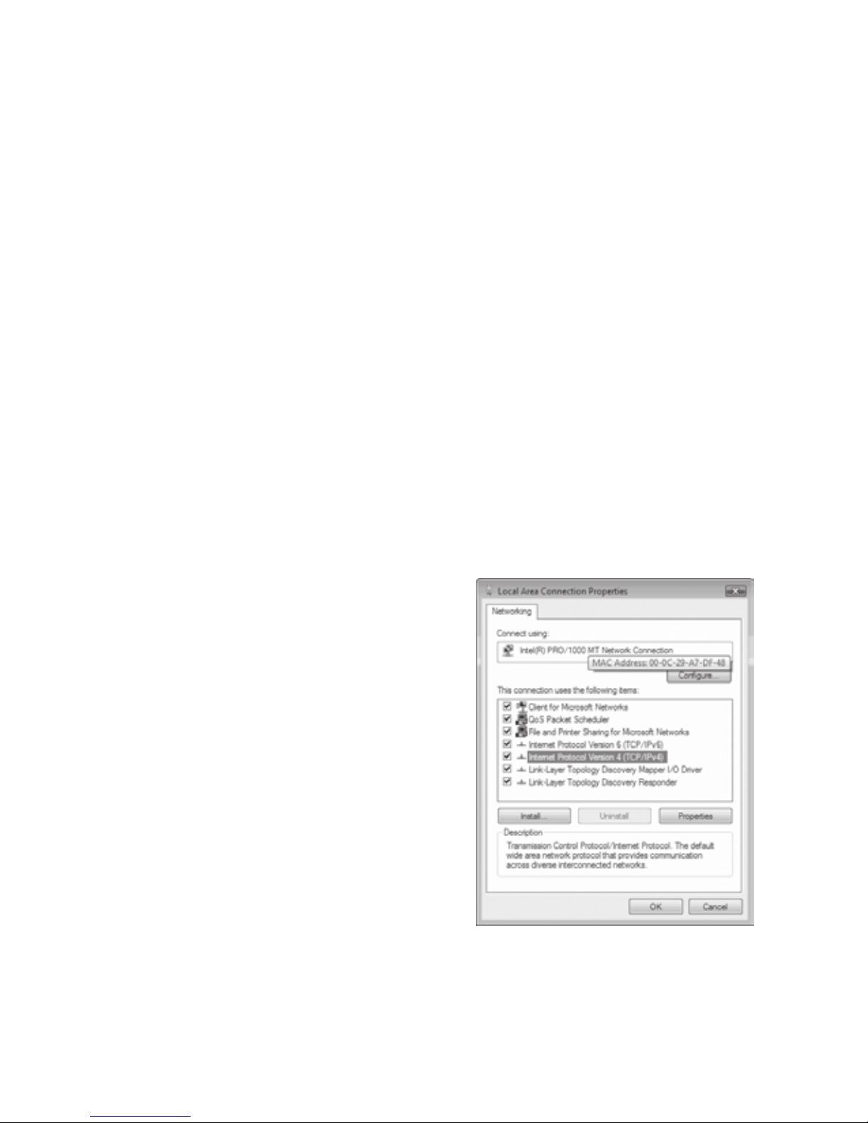
1. Pop up the pull-down menu, click "properties", open the "local connection", and then
double-click the "local connection".
2. Click "properties"
3. Double click the "Internet protocol (TCP/IP)"
4. Obtain the IP address, subnet mask and
gateway
5. Set the corresponding IP address, subnet
mask and gateway of the DVR. Enter the
video recorder‘s [Main Menu] [Conguration
Management] [Network Configuration].
Input the IP address, subnet mask and
gateway. Among them, the subnet mask
and gateway are the same to the Internet
protocol (TCP/IP) parameters. The last one
of the IP addresses must be different while
all the previous gures should be the same
to ensure the same network segment. For
example, IP address: 192.168. 2. X, X can be
any integer between 0-255 except 255 and
1, subnet mask is: 255.255.255.0. Gateway
is: 192. 168. 2. 1.6. After completing the above settings, open the IE browser and input
the IP address set in the DVR network settings, for example, 192.168.1.X, click "enter",
then the network will automatically download controls (The settings property of IE
browser must allow control download. For specic settings pls refer to appendix -1)
Page 34
30
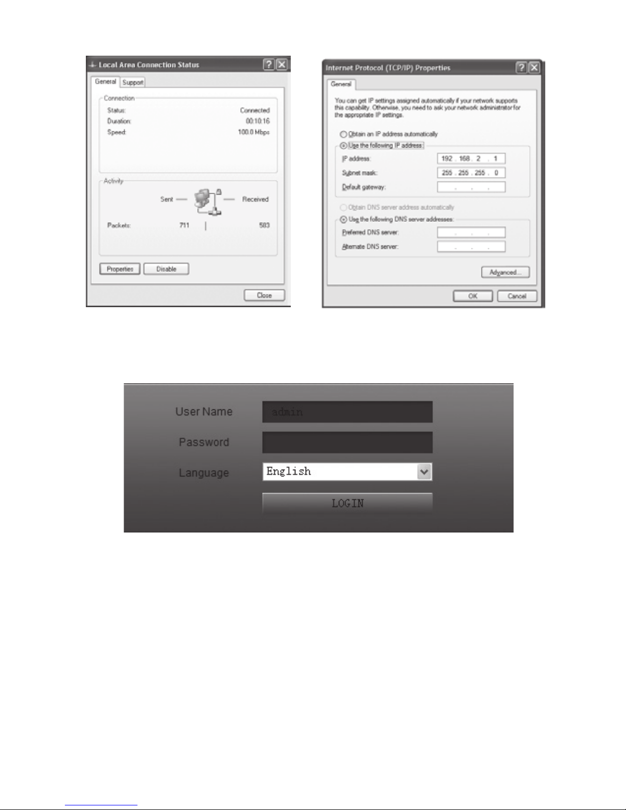
7. After the controls download is completed, pop up login in dialog.
Pic 5-4 log in
Page 35
31
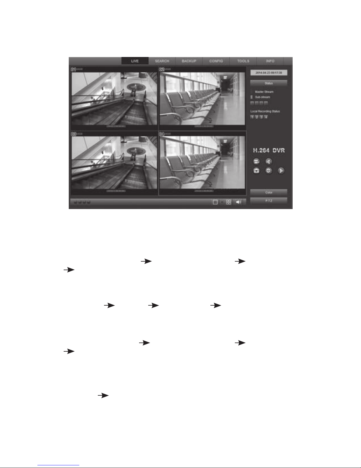
8. Enter username of the device and password In the login window, click "ok" and you can
enter the preview interface as following below.
5.1.2 WAN
1.Connecting DVR by PPPOE
Step 1: Enter DVR Main Menu
Conguration Management Network Conguration
Network, as shown in gure 4-34, tick and select PPPOE directly. It’s no need
to set the DVR's network address, address mask, gateway, just ll in the user name
and password which are provided by telecom operators in the user name and
password elds
Step 2: Enter DVR
main menu Information View Network View to obtain the
IP address and then enter the PC browser interface, input the IP address, for
example,http://210.21.229.138, to enter the control download interface.
2. Connecting DVR through a Router.
Step 1: Enter DVR Main Menu
Conguration Management Network Conguration
Network, as shown in gure 4-34, manually input the IP address, subnet mask
and gateway or tick and select “automatically obtain IP”.
Step 2: When the user conrms LAN can be connected, enter the router to do port
mapping and log in the management interface of the router through the browser. In
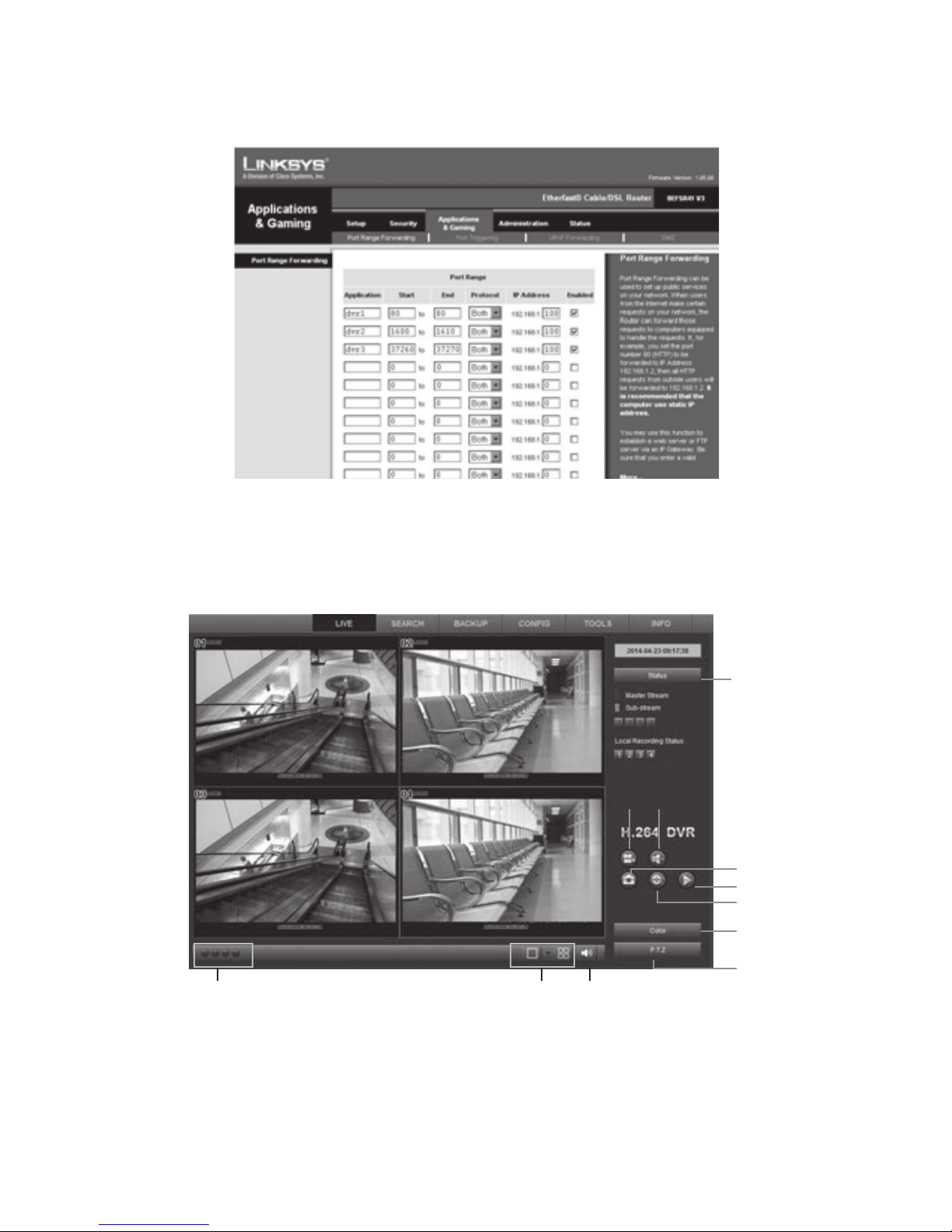
this user manual, let’s take Linksys router as an example, In the router "Applications
& Gaming"
"Port Range Forwarding" map the corresponding DVR's IP address
and port, and each DVR has two corresponding ports. (You can add the LAN
IP address of the DVR to the DMZ host. Different router conguration method is
different, for detail, you can view the router manual).
After mapping the port, you can nd the present WAN IP address in the “running status” of
Page 36
32
the router. You can access DVR via WAN IP address plus http port number directly, such
as http://113.108.119.20, HTTP port number: then enter the control download interface.
5.2 Remote Live Preview
After open the page, the remote preview picture will show as below:
1. Camera Indicator
A green light indicates manual recording or scheduled recording; red light indicates sensor
alarm recording; yellow light indicates motion detection recording; blue light indicates video
loss. For a single channel having several recording mode, the indicating light only displays
the preferred recording mode. The priorities are: Video Loss > Sensor Alarm> Motion
(4)
(7) (8)
(6)
(5)
(9)
(10)
(11)
(3)(2)(1)
Page 37

33
Detection>Schedule Recording= Manual Recording, the 8 lights are respectively represent
8 channels.
2. Screen display mode (synchronization with the congurated device)
3. Volume adjustment 4. Snapshot
5. The Local recording 6. Playback
7. Remote Recording manually 8. Voice Intercom Switch
9. Color Conditioning 10. PTZ control 11. Channel Status
Appendix-1 FAQ
1. After turning on, the DVR can not switch on normally.
Possible reasons:
1. The power supply is not correct.
2. Incorrect power connection.
3. Power supply is defective.
4. A program error has occurred .
5. The hard disk is damaged or something is wrong with the hard disk cables
6. The control panel is damaged.
7. The main board of the DVR is damaged.
2.The DVR reboots automatically or frequently stops working after booting up for a
few minutes
Possible reasons
1. The input voltage is not stable or too low.
2. The hard disk is damaged or the hard disk cables are broken.
3 The power supply is faulty.
4. The front-end video signal is not stable.
5. Poor heat dissipation, too much dust, bad running environment for the DVR.
6. Something is wrong with the hardware of the DVR .
3. Can not detect hard disk after switch on.
Possible reasons
1. The hard disk power supply cable is not connected.
2 . The cables of the hard disk are damaged.
3. The hard disk is damaged.
4. The SATA port of the main board is damaged.
4. No video output in single channel, multiple channels and all channels.
Possible reasons
1. The program is not matched. Please upgrade the program again
2. The image brightness is all 0. Please restore the default setup.
Page 38

34
3. There is no video input signal or the signal is too weak.
4. The hardware of the DVR is damaged.
5. Real-time image problems such as serious distortion of the image color or the
brightness and so on
Possible reasons
2. The DVR is not matched with the impedance of the monitor.
3. The video transmission distance is to long, or the video loss within the cable is too great.
4. The setting of color and brightness for the DVR is wrong.
6. Can not nd video les in local playback.
Possible reasons:
1. Something is wrong with the data cable or the jumper of the hard disk
2. The hard disk is damaged or no video data.
3. Upgraded software has been installed which is not compatible.
4. The video les you want to see are overwritten.
7. Appear blurred screen when see the local video
Possible reasons
1. The video quality is set too low.
2. The program data reads wrongly, may be restored after rebooting the DVR.
3. Something is wrong with the data cable or the jumper of the hard disk.
4. The hard disk is damaged.
5. The hardware of the DVR is damaged.
8. No audio signal in the surveillance window.
Possible reasons
1. Channel not activated for audio recording.
2. The audio cable is damaged.
3. The hardware of the DVR is damaged.
9. There is audio signal in the surveillance window but no audio signal when
playback
Possible reasons
1. The audio option is not chosen.
2. The corresponding channel is not connected with the video. When the image appear
blue screen the playback will be intermittent
10. The time display is wrong.
Possible reasons
1. The setting is wrong.
2. The battery is loose or the battery voltage is too low.
11. DVR can not control the PTZ.
Possible reasons
1. Something wrong with the PTZ camera.
Page 39

35
2. The baud rate, address, protocol settings of the front-end PTZ and device PTZ not
matched
3. RS485 cable is incorrectly connected (reversed)
4. When multiple decoders are connected, the far end of AB cable of the PTZ decoder
must add a 120 ohm resistor to remove reection and aid impedance matching, otherwise
it may make the PTZ control unstable.
12. The motion detection is not working
Possible reasons:
1. The time period is not correct.
2. The wrong motion detection area has been selected.
3. The sensitivity is too low.
13. Can not login via web or client.
Possible reasons
1. ActiveX is held back.
2. Something is wrong with network connection.
3. Network setting problems
14. No Image or poor quality image when previewing image or playback les
Possible reasons
1. Interference on, or poor quality network.
2. The user does not have preview privileges.
3. The device has no image output
15. Something wrong with the USB backup.
Possible reasons
1. The data size is to large. Stop recording and carry out a backup.
2. The data volume exceeds the backup storage capacity and it will cause burning errors
3. The backup device is not compatible.
4. The backup device is damaged.
16. Alarm is not working.
Possible reasons
1. The alarm settings are incorrect.
2. The connection of the alarm is not correct.
3. The alarm input signal is not correct.
17. The remote controller can not control.
Possible reasons
1. The remote control address is not correct.
2. The remote control distance is too far or the angle is too offset.
3. The battery is at.
4. The remote controller or the front panel of the DVR is damaged.
Page 40
36
18. If you forget your password
Please contact the local customer service or call service phone of the head ofce. We will
tell you how to solve the problem according to the device model and the program version.
19. When use IE browsering, the controls can not be downloaded
Please follow the following steps to operate:
1. When IE browser prevent downloading controls, please do the following setting
operation
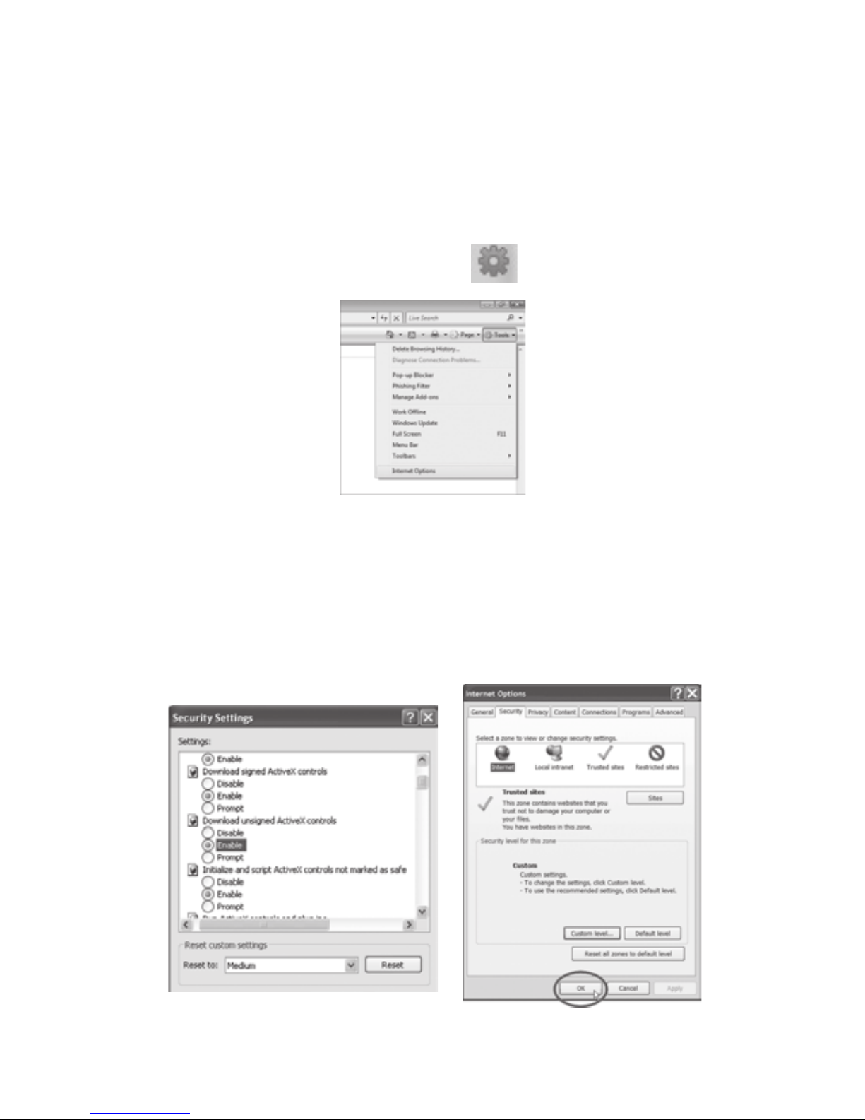
(1) Open the IE browser and click the "tool" button
, pop up the gure below:
(2) Click on the "Internet ",pop up the following figure 8-1 window ,and then select
"security"
(3) Click "custom level" and pop-up the setting window, please refer to the pic"8-2 and
enable all the function of "ActiveX controls and plug-ins" ,and then Click "nish", conrm
the settings.
2. If you want to prevent other plug-ins or virus control, please close the rewall and all
antivirus softwares.
Page 41
37
20. In the operating system of VISTA and Win7, how to solve the problem when
downloading codec control is prevented?
There are two solutions:
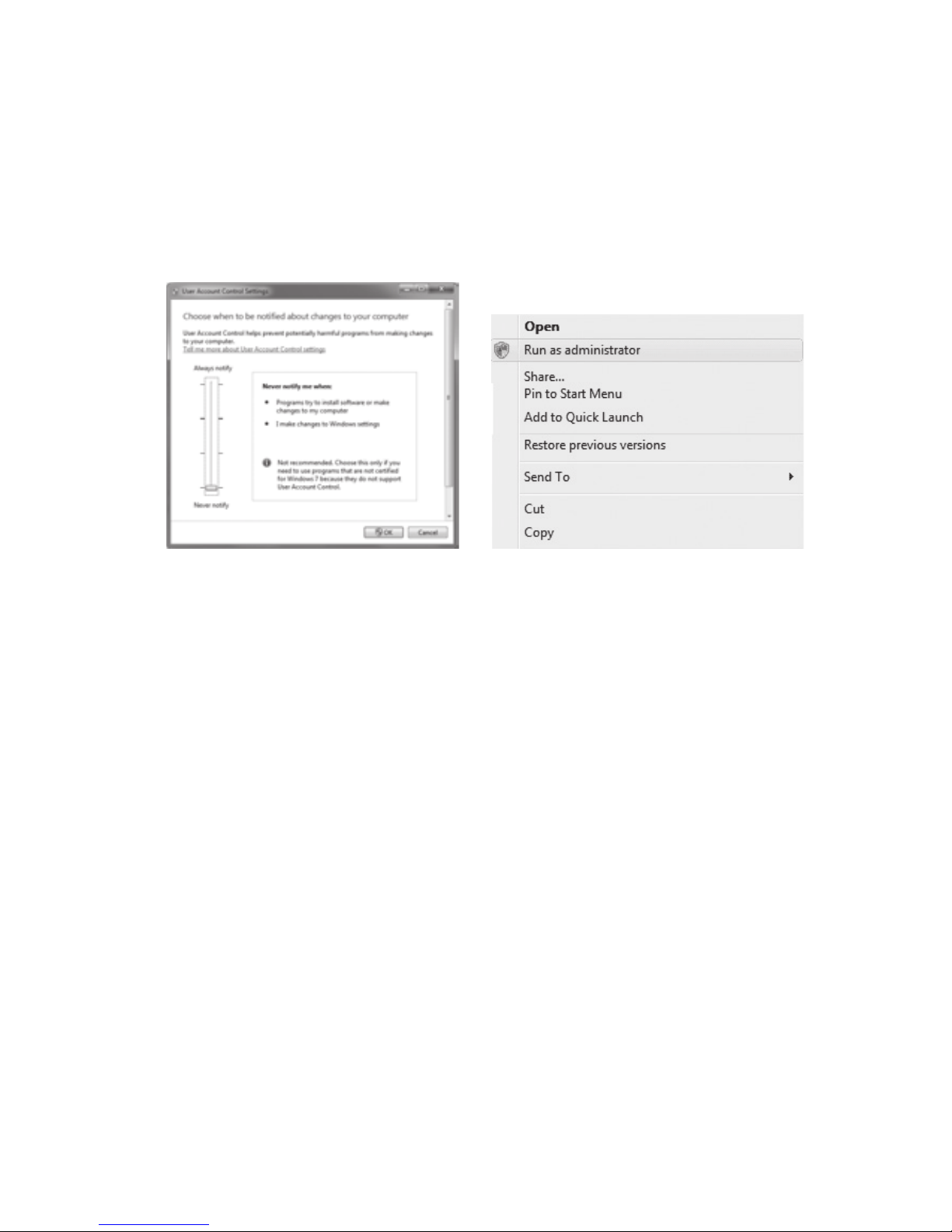
Go to Control Panel \ User Accounts and Family Safety \ User Accounts \ Change User
Account Control Setting Interface (as shown in pic 13-1), just select never notice.
Or you can right-click the IE browser and select "run as an administrator". As shown in pic
13-2:
Pic 13-1 pic13-2
Page 42

38
Appendix 2.Hard Disk Capacity Calculation
Make sure the hard disk is installed and successfully formatted when install the DVR for
the rst time.
1. The capacity of the Hard disk itself
There is no capacity limit of single hard disk for DVR. You can choose 10G or more.. We
recommend hard disk of 500G~2T for better stability.
2. Total Capacity Option
The calculation formula of hard disk capacity is:
Total capacity(M) =channel numbers*time(hour)*occupied capacity for an hour(M/hour)
Similarly, the calculation formula of recording time is:
Recording time(hour)= Total capacity(M)
Occupied Capacity for an hour(M/hour)*the channel numbers
The DVR introduces theH.264 compression technology. Its dynamic range is very large so
the hard disk capacity calculation is based on the stream to count the estimated values of
les created by each channel in an hour.
Example:
For a 500G HDD, real -time CIF recording, it can keep recording for about 25 days. The
occupied space of HDD for single channel is 200M/H, if 4channels real-time CIF recording
for 24hours, the estimated recording days is: 500G/(200M/H*24H*4ch)=26 days
Page 43

Page 44

 Loading...