

Page 1

Prysm LCD Visual Workplace
Assembly Guide
Prysm 98
Prysm 86
Prysm 85
Prysm 85 Dual
Prysm 84
Prysm 75
Prysm 65
Prysm 65 Core
December 2017
520-00072-00 Rev 12
Page 2

NOTICE
Copyright © 2017, Prysm Inc.
All information contained herein is the property of Prysm, Inc. No part of this publication may be reproduced, stored in a retrieval system, or
transmitted, in any form or by any means, electronic, mechanical, photocopying, or otherwise, without the prior written consent of the
publisher. Any software referred to herein is furnished under license and may only be used or copied in accordance with the terms of such
license. Printed documents are not controlled, therefore identifying the document's most current revision is the holder's responsibility.
TRADEMARK ACKNOWLEDGMENT
Prysm and the Prysm Logo are registered trademarks of Prysm, Inc. Prysm, Inc. disclaims any proprietary interest in brands and product
names used in this document that are trademarked by another entity.
PATENTS
Prysm products discussed in this documentation are protected by patents issued and pending in the US and other countries. Please see
www.prysm.com/patents for additional information.
WARRANTY
The information contained herein is subject to change without notice. The only warranties for Prysm products and services are set forth in the
express warranty statements accompanying the applicable customer agreement. Nothing herein should be construed as constituting an
additional warranty. This document is provided solely for general informational purposes. Prysm shall not be liable for technical or editorial
errors or omissions contained herein. Video wall display characteristics may vary from the tile display characteristics specified herein based
upon factors including, but not limited to, the size of the video wall and display configuration settings.
ABOUT PRYSM
Prysm is defining a new way of work. One where applications, content, video conferencing and the Web can all be easily combined into a
visual workspace where teams can create, edit and share. These interactive workspaces are stored in the cloud and available on any sized
screen. Prysm’s Visual Workplace solutions span from executive briefing center to home office — and every size workplace in between.
Today, Prysm powers 20 percent of the Fortune 500 and our customers are leaders in all industries including technology, energy, finance,
healthcare, media and universities. To define your company’s new way of work, visit prysm.com.
PRYSM, Inc.
180 Baytech Drive, Suite 200
San Jose, CA 95134
1.877.99.PRYSM
+1.408.586.1100
PRYSM.com
[email protected]
24x7 support: 1.877.44.PRYSM
Page 3

Contents
Preface . . . . . . . . . . . . . . . . . . . . . . . . . . . . . . . . . . . . . . . . . . . . . . . . . . . . . . . . . . . . . . . . . . . . . . . . . . . . . . . . . . . . . . . . . . . 4
Definitions . . . . . . . . . . . . . . . . . . . . . . . . . . . . . . . . . . . . . . . . . . . . . . . . . . . . . . . . . . . . . . . . . . . . . . . . . . . . . . . . . . . . . 6
1. Required Tools . . . . . . . . . . . . . . . . . . . . . . . . . . . . . . . . . . . . . . . . . . . . . . . . . . . . . . . . . . . . . . . . . . . . . . . . . . . . . . . . . . . 7
2. Overview of Prysm LCD Visual Workplace Components . . . . . . . . . . . . . . . . . . . . . . . . . . . . . . . . . . . . . . . . . . . . . . . . . . . 8
2.1 Parts of the Prysm LCD Visual Workplace Stand . . . . . . . . . . . . . . . . . . . . . . . . . . . . . . . . . . . . . . . . . . . . . . . . . . . . 9
2.2 Product Component Diagrams . . . . . . . . . . . . . . . . . . . . . . . . . . . . . . . . . . . . . . . . . . . . . . . . . . . . . . . . . . . . . . . . . . 17
3. Assembly Procedures . . . . . . . . . . . . . . . . . . . . . . . . . . . . . . . . . . . . . . . . . . . . . . . . . . . . . . . . . . . . . . . . . . . . . . . . . . . . . 24
3.1 Assemble the Stand . . . . . . . . . . . . . . . . . . . . . . . . . . . . . . . . . . . . . . . . . . . . . . . . . . . . . . . . . . . . . . . . . . . . . . . . . . 25
3.2 Install the Display Support Assembly . . . . . . . . . . . . . . . . . . . . . . . . . . . . . . . . . . . . . . . . . . . . . . . . . . . . . . . . . . . . . 28
3.3 Install the Camera Support . . . . . . . . . . . . . . . . . . . . . . . . . . . . . . . . . . . . . . . . . . . . . . . . . . . . . . . . . . . . . . . . . . . . . 31
3.4 Install the System Cabinet . . . . . . . . . . . . . . . . . . . . . . . . . . . . . . . . . . . . . . . . . . . . . . . . . . . . . . . . . . . . . . . . . . . . . . 33
3.5 Set up the System Components . . . . . . . . . . . . . . . . . . . . . . . . . . . . . . . . . . . . . . . . . . . . . . . . . . . . . . . . . . . . . . . . . 35
3.6 Install the Display . . . . . . . . . . . . . . . . . . . . . . . . . . . . . . . . . . . . . . . . . . . . . . . . . . . . . . . . . . . . . . . . . . . . . . . . . . . . 37
3.7 Install the Keyboard Shelf . . . . . . . . . . . . . . . . . . . . . . . . . . . . . . . . . . . . . . . . . . . . . . . . . . . . . . . . . . . . . . . . . . . . . . 41
3.8 Apply the Labels . . . . . . . . . . . . . . . . . . . . . . . . . . . . . . . . . . . . . . . . . . . . . . . . . . . . . . . . . . . . . . . . . . . . . . . . . . . . . 43
4. Cabling Procedures . . . . . . . . . . . . . . . . . . . . . . . . . . . . . . . . . . . . . . . . . . . . . . . . . . . . . . . . . . . . . . . . . . . . . . . . . . . . . . . 45
4.1 Cable the Prysm 98 . . . . . . . . . . . . . . . . . . . . . . . . . . . . . . . . . . . . . . . . . . . . . . . . . . . . . . . . . . . . . . . . . . . . . . . . . . . 46
4.2 Cable the Prysm 86, 85, 84, 75, 65, and 65 Core . . . . . . . . . . . . . . . . . . . . . . . . . . . . . . . . . . . . . . . . . . . . . . . . . . . . 53
4.3 Cable the Prysm 85 Dual . . . . . . . . . . . . . . . . . . . . . . . . . . . . . . . . . . . . . . . . . . . . . . . . . . . . . . . . . . . . . . . . . . . . . . 66
5. Startup Configuration . . . . . . . . . . . . . . . . . . . . . . . . . . . . . . . . . . . . . . . . . . . . . . . . . . . . . . . . . . . . . . . . . . . . . . . . . . . . . . 80
Page 4

Prysm LCD Visual Workplace Assembly Guide 520-00072-00 Rev 12
4Copyright © 2017, Prysm Inc. All rights reserved. Confidential and proprietary.
Preface
Purpose
This procedure describes how to assemble and cable the stand and display.Prysm LCD Visual Workplace
Scope
This document covers the hardware setup of the stand components for the following products:Prysm LCD Visual Workplace
Prysm 98 Visual Workplace
Prysm 86 Visual Workplace
Prysm 85 Visual Workplace
Prysm 85 Dual Visual Workplace
Prysm 84
Prysm 75
Prysm 65 Visual Workplace
Prysm 65 Core Visual Workplace
Related Documents
Title Document Number
Prysm Visual Workplace Core Firmware Update Procedure 230-00467-00
Application Appliance Installation Guide 520-00064-00
Prysm Application Suite End User Guide 520-00044-00
Wall Mount Recommendations for Prysm LCDs 551-00061-00
Prysm QuadLynk Installation Guide 520-00106-00
Prysm LCD Visual Workplace User Guide 520-00049-00
Safety
Assembly and testing of the Prysm LCD Visual Workplace stand and components should be done only by Prysm-certified technicians or
FAEs familiar with the process.
NOTICE OF NAME CHANGES
At publication of this document, Prysm Products are undergoing name changes. This guide refers to some documents that still
have the old product names, such as and .Cascade Synthesis
IMPORTANT
Ensure you have the latest version of document, go to: this
Kaybus: or .https://prysm.kaybus.com/ http://www.prysm.com/resources
Page 5

Prysm LCD Visual Workplace Assembly Guide 520-00072-00 Rev 12
5Copyright © 2017, Prysm Inc. All rights reserved. Confidential and proprietary.
Revision History
Revision Number Date Change Description Author
Rev 01 October 2015 Initial Release DY
Rev 02 November 2015 Info added for .Prysm 85 Dual
Minor changes made throughout.
DY
Rev 03 December 2015 Added Addendum with IIC install instructions for and a couple of other minorPrysm 65 Core
notes.
DY
Rev 04 February 2016 Changed title to "Prysm LCD Visual Workplace Solution Assembly Guide".
Simplified Related Documents section. Moved Addendums into proper places in text. Added
product detail drawings for major components. Added full cabling diagrams for all products.
Moderately revised document structure for new cabling section. Modified numerous drawings for
clarity. Added information for the 98" display.
DY
Rev 05 March 2016 Added clarifications to ambiguous instructions. Added a couple of graphics. Corrected minor
errors to text and graphics.
DY
Rev 06 August 2016 Added USB extender cable for Keyboard & Mouse dongle. Replaced Prysm Application
Appliance reference with new designation; updated pictures of Application Appliance. Added
warnings on pages 12 and 16-19 about ensuring plastic film on the display unit is removed.
Added step to that effect on page 35.
DR
Rev 07 March 2017 Change of some kit part numbers, some screw part numbers, and the stand part number.
Changed name of product to Prysm Visual Workplace. Some minor clean-up to SI metric
standards.
DR
Rev 08 May 2017 Added a Warning that the casters and feet must be locked in place by tightening the top locking
nut.
Changed Prysm logo on cover to updated version.
DY
Rev 09 June 2017 Changed inclusion of the IIC to be optional, not standard.
Replaced graphic showing power cables to correct part number (771-00331-00 to
771-00311-00).
DY
Rev 10 August 2017 Replaced 65" display image with Avocor 65" 4K display showing different ports, speakers, etc.
Replaced keyboard and mouse with keyboard with trackpad.
Added warning about tightening the casters and the locking nut.
DY
Rev 11 December 2017 Added information for the Prysm 86 4K Display. Added refs to QuadLynk. DY
Rev 12 December 2017 Added information for the Prysm 75 and Prysm 84 4K Display. DY
Page 6

Prysm LCD Visual Workplace Assembly Guide 520-00072-00 Rev 12
6Copyright © 2017, Prysm Inc. All rights reserved. Confidential and proprietary.
Definitions
Term Definition
AA Prysm Application Appliance.
Application
Suite
End-user software that enables collaboration on Prysm video walls and displays. (As of this writing, this name is changing
over to Application Suite.)
Arena Product Life Cycle Management (PLM) database for parts and related documents. The supplier accesses the latest part and
document information through Arena. URL is .https://app.bom.com
Badge Prysm-branded identification tag placed near the front of each Prysm Application Appliance and Prysm LCD Display.
BOM Bill of Materials. Compliance document signed by the supplier to certify that the product was built and configured to Prysm
specifications.
Confluence Team collaboration software written in Java and used primarily in corporatedeveloped and marketed by Atlassian. It is
environments.
Egnyte Prysm file server that stores the latest Prysm Application Appliance software. Prysm Application Appliance Specification
documents are also available on Egnyte. URL is .https://prysm.egnyte.com
IIC Interactive Input Controller kit consisting of a Crestron HD Amplifier, a ViewHD HDMI Splitter Amplifier, and an Adderlink
ipeps Controller for control of an in-room PC from the display.
Live
Sources
Video input devices connected to the Prysm Application Appliance for display in the Prysm Application Suite.
Kaybus Primary repository for documentation for field use. URL is .https://prysm.kaybus.com
PN Part Number. 10-digit Prysm Arena part number for tracking documents and parts. 10-digit numbers in parentheses
designate the part number for the item mentioned immediately before.
PO Purchase Order. Document that initiates and describes the products that the Supplier manufactures for Prysm.
Project In Prysm Application Suite, a named collection of files and associated authorized users.
QuadLynk A device that allows the sharing of video sources such as laptops, cameras, media players, and video teleconferencing
systems over a network.
UI User Interface.
Web
Admin
Graphical User Interface (GUI) that allows developers, engineers, installers, and End-Users access to the Prysm Application
Suite to define, configure, commission, and provision a system through a web-based interface.
Workspace A named work area in Application Suite where media objects (files, videos, etc.) can be presented. The point of collaboration
between local and remote users.
Page 7

Prysm LCD Visual Workplace Assembly Guide 520-00072-00 Rev 12
7Copyright © 2017, Prysm Inc. All rights reserved. Confidential and proprietary.
1. Required Tools
The following tools are necessary to assemble the Prysm LCD Visual Workplace stands:
Tool Sizes Description
Utility knife or boxcutter To cut strapping on cartons
Phillips screw driver #2
Open end wrenches 17 mm
20 mm
Box end will not work.
Socket wrench with sockets 10 mm
13 mm (or 1/2")
Hex wrenches 4 mm
5 mm
6 mm
Comes with stand
Comes with stand
Measuring tape 6 ft or more Inches
Small square Optional
Padding Blanket or other soft material
on which to assemble parts
Labels or paper tape To label cable ends
Page 8

Prysm LCD Visual Workplace Assembly Guide 520-00072-00 Rev 12
8Copyright © 2017, Prysm Inc. All rights reserved. Confidential and proprietary.
2. Overview of Prysm LCD Visual Workplace Components
The following subsections describe the different parts of the stand, and the controls and ports of the electricalPrysm LCD Visual Workplace
components and LCD displays. The subsections are:
2.1 Parts of the Prysm LCD Visual Workplace Stand
2.2 Product Component Diagrams
NOTE
If you are mounting an LCD display on a wall rather than a Prysm Visual Workplace stand, see the Technical Bulletin Wall Mount
(551-00061-00).Recommendations for Prysm 65, 86, 85, and 98 LCDs
Page 9
Prysm LCD Visual Workplace Assembly Guide 520-00072-00 Rev 12
9Copyright © 2017, Prysm Inc. All rights reserved. Confidential and proprietary.
2.1 Parts of the Prysm LCD Visual Workplace Stand
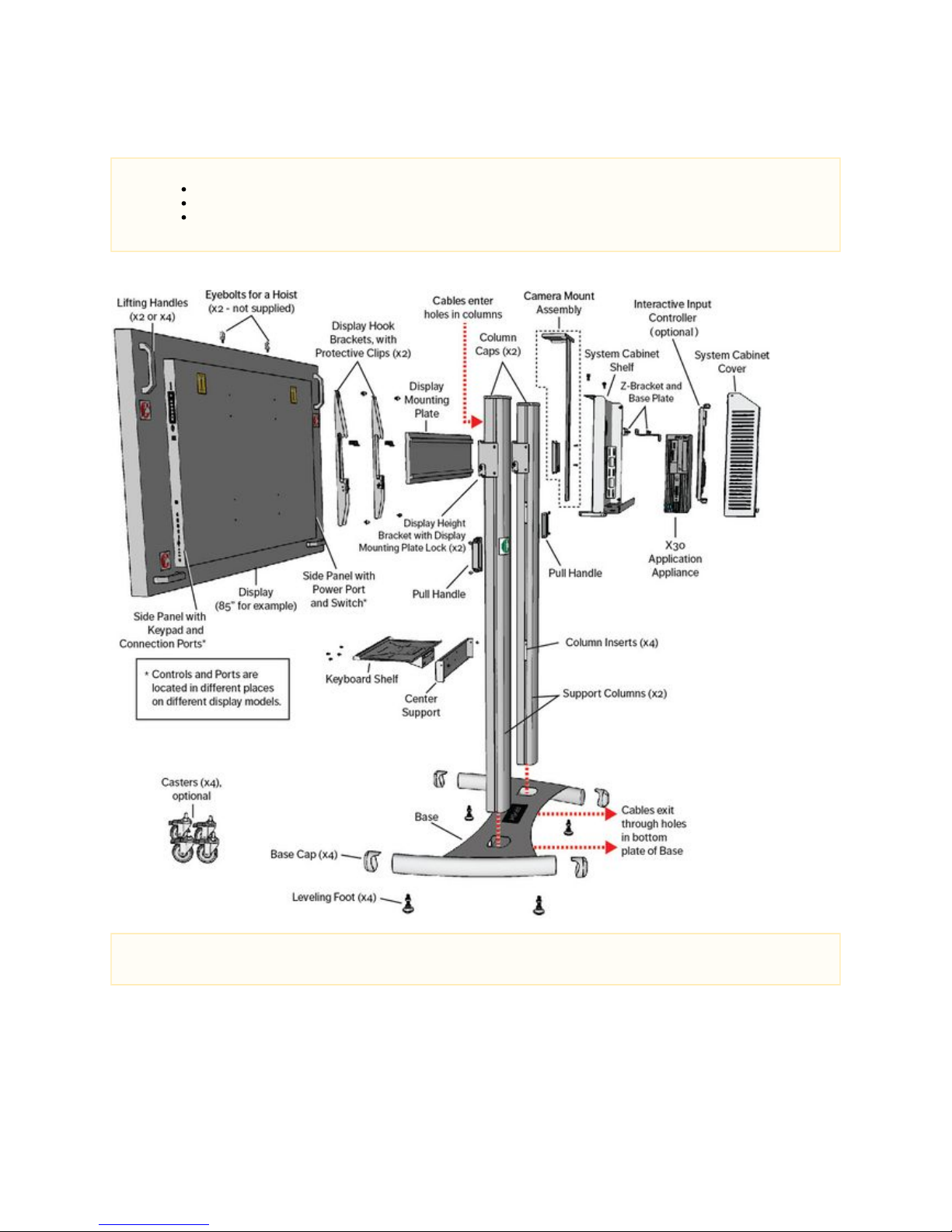
This following illustration refers to the main parts of a Prysm 86, Prysm 85, Prysm 85 Dual, Prysm 65, and Prysm 65 Core LCD Visual
Workplace stand.
NOTES
The Prysm 98 is a wall-mount display and does not come with a stand.
The Prysm 98 does not come standard with an Interactive Input Controller.
The Open Me First carton contains replacements for several stand parts. Ensure that these parts are replaced for optimal
configuration.
NOTE
To see the exact location of ports on a specific display model, see .2.2 Product Component Diagrams
Page 10
Prysm LCD Visual Workplace Assembly Guide 520-00072-00 Rev 12
10Copyright © 2017, Prysm Inc. All rights reserved. Confidential and proprietary.
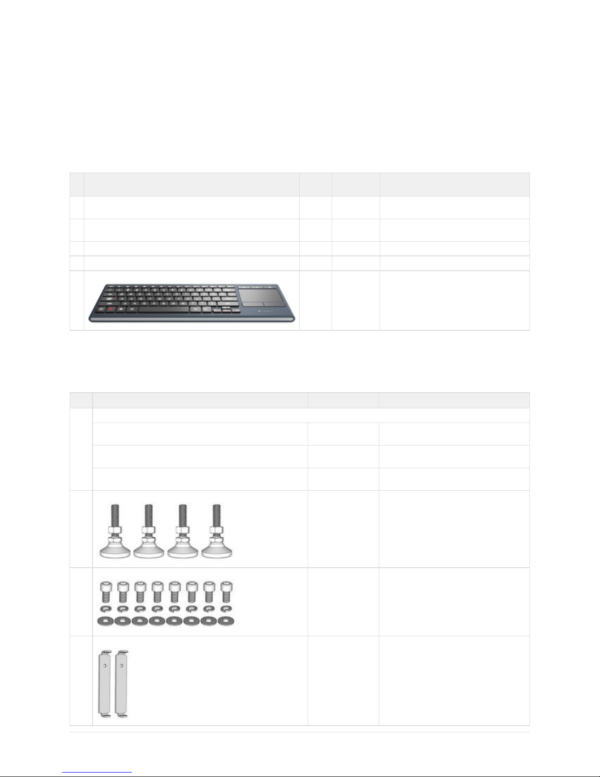
2.1.1 Parts Lists
The following tables show the basic components of the Prysm LCD Visual Workplace stand and their part numbers, broken down by shipping
carton. You will have received only the cartons that apply to the ordered Prysm product.
Prysm 98 "Open Me First" carton
Part #: 050-00361-00
Prysm 98 only. Wall-mount only.Applies to:
# Item Length Part
Number
Notes
1 Prysm LCD Visual Workplace Assembly Guide N/A 520-00072-00 This document, used to assemble the Prysm
stand.
1 Prysm Application Suite Quick Guide N/A 520-00066-00 Laminated sheet to be given to the customer as
a reference.
1 USB 2.0 A-Male to Serial (RS-232) cable 10 ft 771-00245-00
1 DisplayPort, Male-to-Male cable, with latches 6 ft 771-00308-00
1 Wireless Keyboard with Trackpad N/A 781-00222-00
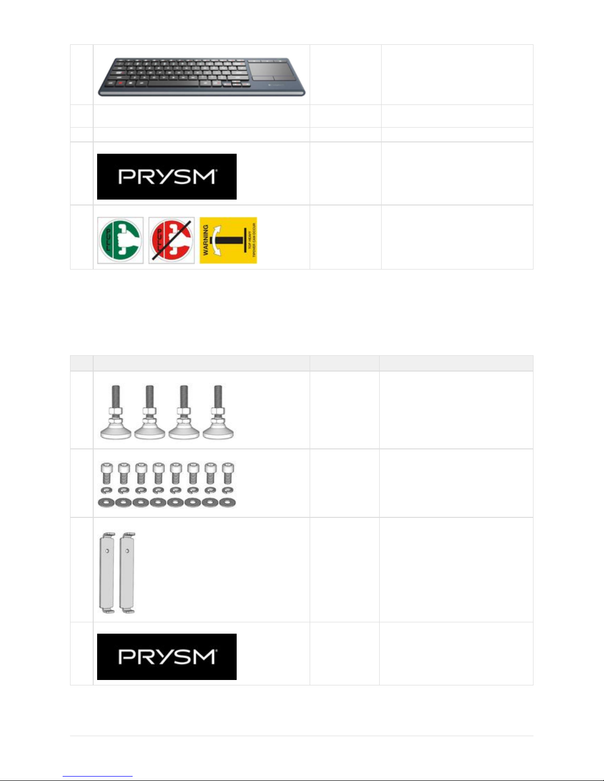
Prysm 86, Prysm 85, or Prysm 65 "Open Me First" Carton
Kit Part #: 050-00352-00
Prysm 85, Prysm 85 Dual, Prysm 65, and Prysm 65 Core.Applies to:
# Item Part Number Notes
1 ea. Documentation:
READ ME FIRST 520-00075-00 Single sheet, to be read before assembling the
stand.
Prysm LCD Visual Workplace Assembly Guide 520-00072-00 This document, used to assemble the stand and
display.
Prysm Application Suite Quick Guide 520-00066-00 Laminated sheet to be given to the customer as
a reference.
4 Leveling Feet 773-01358-00 To replace casters at customer request.
8 ea. Display Fastening Hardware
773-00888-16 - M8
hex cap screws
773-00190-00 - lock
washers
773-00738-00 - flat
washers
To fasten Display Hook Brackets to display.
2 Column Slot Inserts
773-01359-00 In addition to the two already installed in the
stand.
Page 11
Prysm LCD Visual Workplace Assembly Guide 520-00072-00 Rev 12
11Copyright © 2017, Prysm Inc. All rights reserved. Confidential and proprietary.
1 Wireless Keyboard with Trackpad 781-00222-00
1 USB 3.0 Type A Male to Female Extension Cable, 6 ft. 771-00340-00 To extend the USB port on the Application
Appliance for the Keyboard dongle.
1 3M 1 inch Dual lock Velcro Tape 776-00151-00 To adhere the dongle on the edge of the display.
1 Prysm Label 110-04886-00 To apply to the base of the stand.
1
sheet
Warning Labels
110-04899-00 To apply to specific places on the stand.
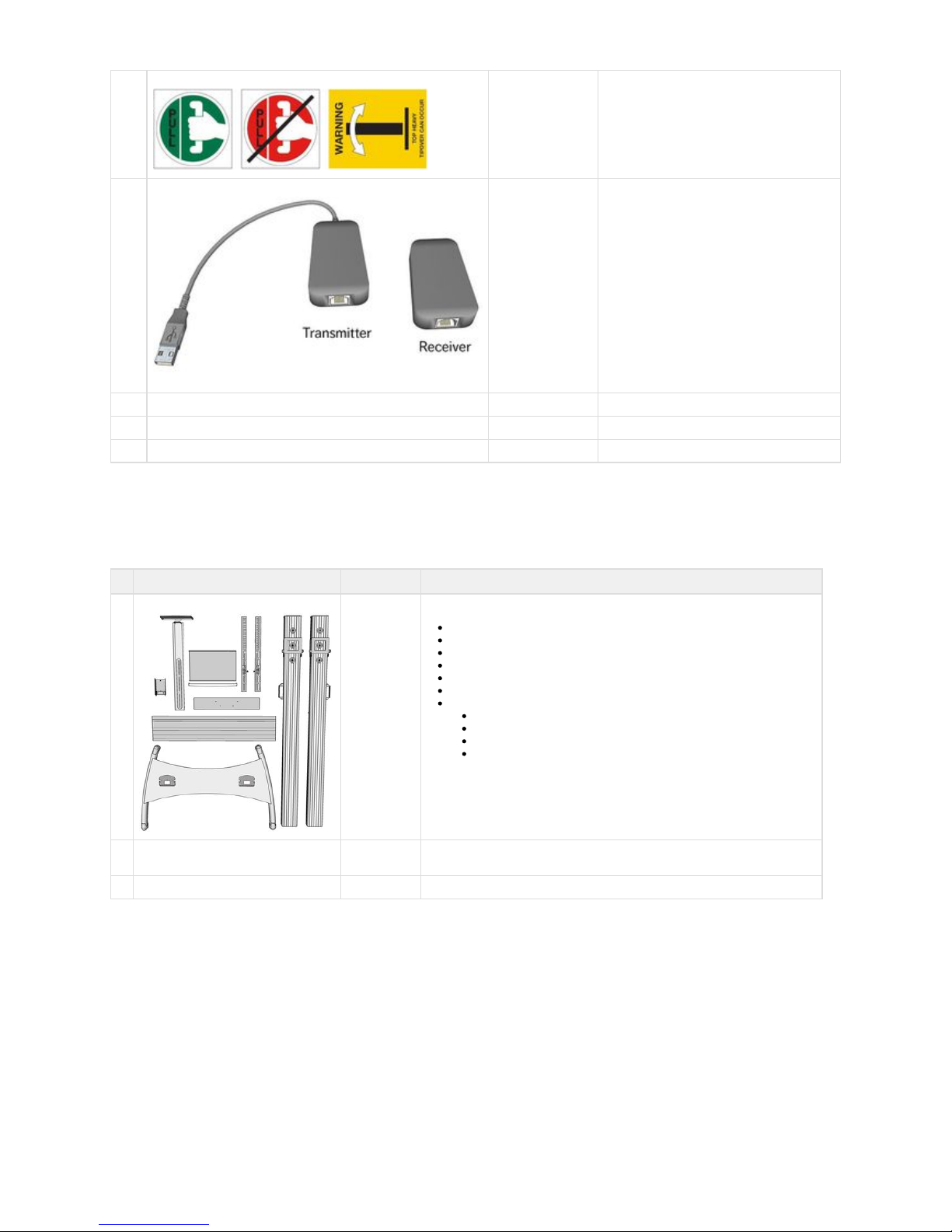
Prysm 85 Dual LCD and Cart Kit Carton
050-00355-00Kit Part #:
Prysm 85 Dual (038-00030-00) for the Secondary Stand and displayApplies to:
# Item Part Number Notes
4 Leveling Feet 773-01358-00 To replace casters on Secondary Stand at
customer request.
8 ea. Display Fastening Hardware
773-00888-16 - M8
hex cap screws
773-00190-00 - lock
washers
773-00738-00 - flat
washers
To fasten Display Hook Brackets to Secondary
Display.
2 Column Slot Inserts
773-01359-00 In addition to the two already installed in the
Secondary Stand.
1 Prysm Label 110-04886-00 To apply to the Base of the Secondary Stand.
Page 12
Prysm LCD Visual Workplace Assembly Guide 520-00072-00 Rev 12
12Copyright © 2017, Prysm Inc. All rights reserved. Confidential and proprietary.
1
sheet
Warning Labels
110-04899-00 To apply to specific places on the Secondary
Stand.
1 USB Over UTP Extender (2 parts)
771-00319-00 This two-part extender will be fitted on either end
of the following CAT5e cable.
NOTE: The Extender that comes with the kit may
differ from the one shown here.
1 CAT5e cable, 25 ft 771-00323-00
1 DisplayPort cable, 25 ft 771-00322-00
1 AC Power, NEMA 5-15P to IEC C13, UNIV, 125V, 13A, 20 ft 771-00311-00
Prysm LCD Stand Carton
Kit Part #: 032-00017-01
Prysm 85, Prysm 85 Dual, Prysm 65, and Prysm 65 Core. Does not come with the Prysm 98.Applies to: Prysm 86,
# Item Part Number Notes
1 Prysm Visual Workplace Stand
032-00017-01 Stand parts include:
1 Base with 4 Casters
2 Support Columns
2 Display Hook Brackets
1 Display Mounting Plate
1 Camera Support Bar
1 Camera Support Connector
1 inner carton containing:
1 Keyboard Shelf
1 Wrist Rest
1 Camera Support Platform
1 Center Support
2 Polybags of fastening hardware
and tools
N/A Keep only the long screws in A2 section and the two hex wrenches from B2 section.
1 Assembly Guide N/A Discard. Use this Assembly Guide from the READ ME FIRST carton.
Page 13
Prysm LCD Visual Workplace Assembly Guide 520-00072-00 Rev 12
13Copyright © 2017, Prysm Inc. All rights reserved. Confidential and proprietary.
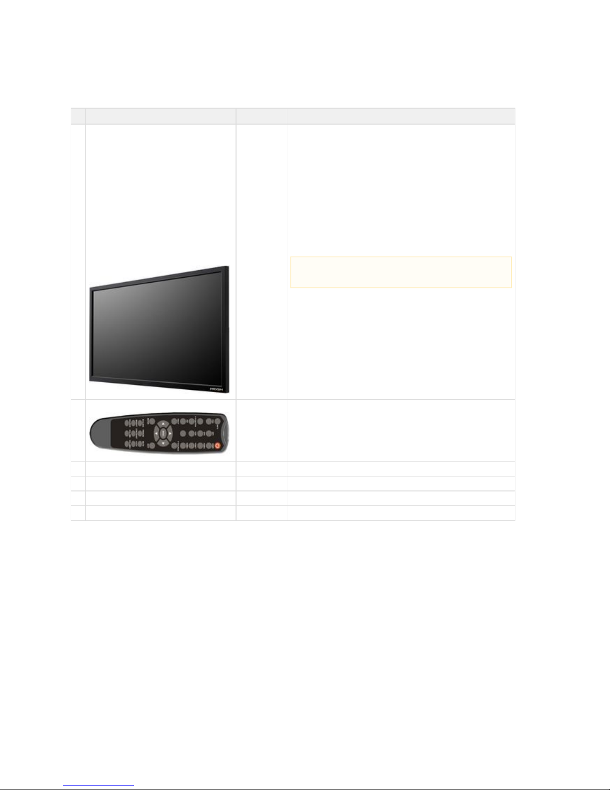
Prysm LCD Display Carton(s)
See individual display part numbers in table.Kit Part #:
Prysm 98, Prysm 86, Prysm 85, Prysm 85 Dual, Prysm 65, and Prysm 65 CoreApplies to:
# Item Part Number Notes
1
1
1
2
1
1
1
1
Prysm 98" display, or
Prysm 86" display, or
Prysm 85" display, or
Prysm 85" displays (Prysm 85 Dual), or
Prysm 84" display, or
Prysm 75" display, or
Prysm 65" display, or
Prysm 65" Core display
030-00060-00
030-00076-00
030-00043-00
030-00043-00
030-00087-00
030-00210-00
030-00042-00
030-00054-00
The Prysm 98 display is a wall-mount 4K display and is not
installed on a stand.
The Prysm 86 comes with a single display.4K
The Prysm 85 comes with a single 4K display.
The Prysm 85 Dual comes with two 4K displays.
The Prysm 84 comes with a single 4K display.
The Prysm 75 comes with a single 4K display.
The Prysm 65 comes with a single 4K display.
The Prysm 65 Core comes with a single 2K display.
1 IR Remote Control (with batteries)
N/A
1 IR Extender cable N/A
1 USB Type A to Type B cable, 6 ft N/A
1 HDMI cable, 6 ft N/A Not used
1 Power cable, 6 ft N/A Only used for the Prysm 98.
NOTE:
Ensure that the plastic covering on the display unit is removed.
Page 14
Prysm LCD Visual Workplace Assembly Guide 520-00072-00 Rev 12
14Copyright © 2017, Prysm Inc. All rights reserved. Confidential and proprietary.
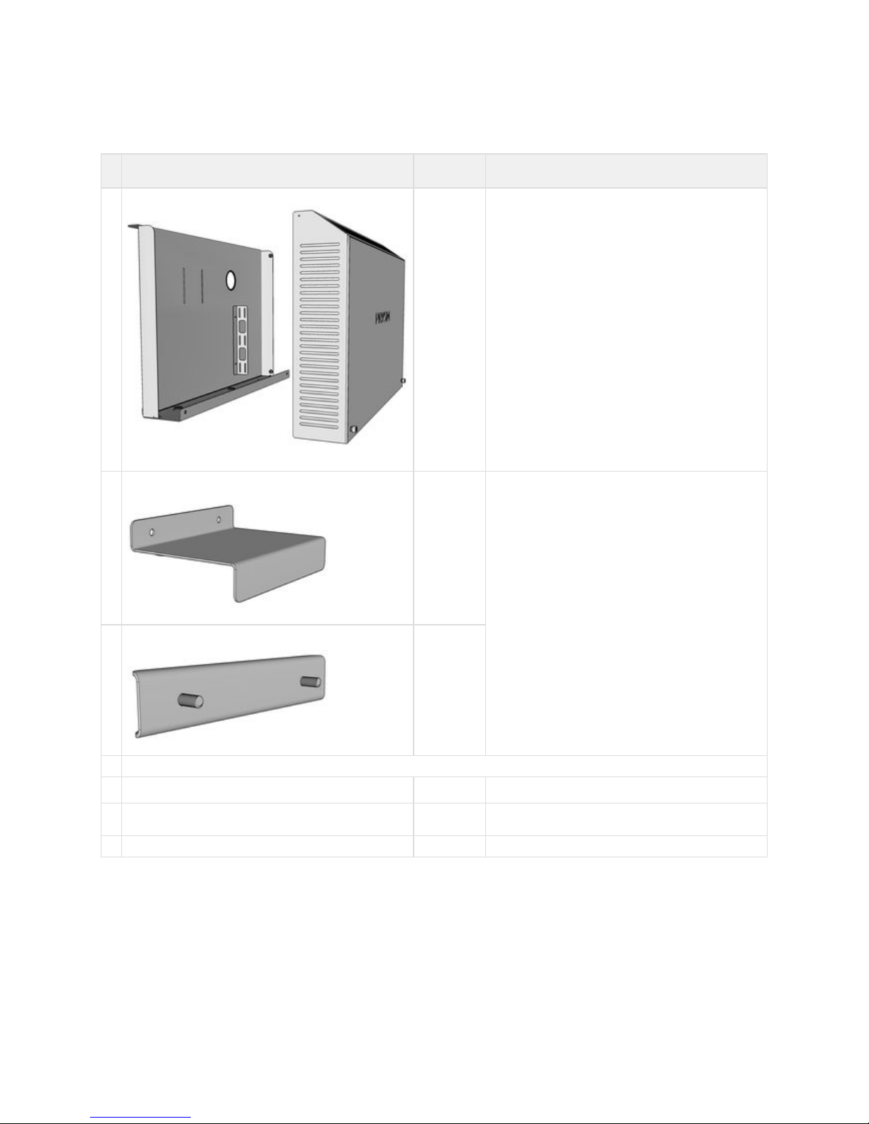
System Cabinet Carton
050-00330-01Kit Part #:
Applies to: Prysm 86, Prysm 85, Prysm 85 Dual, Prysm 65, and Prysm 65 Core
# Item Part
Number
Notes
1 System Cabinet Shelf and Cover
020-01669-00
020-01670-00
To be mounted on the rear of the Prysm stand.
1 Z-Bracket
020-01705-00 Two parts used in combination to hold the X30 in place.
1 Z-Bracket Base Plate
020-01676-00
1 Polybag containing fastening hardware:
2 5/16" flange bolts with 1/2" hex cap
773-01918-00 To attach the System Cabinet to the stand.
2 M6 flanged socket cap screws 773-01267-00 To attach the base of the cabinet to the stand's support
columns.
4 M6 locknuts 773-01206-00 To secure the X30 and IIC into the System Cabinet.
Page 15
Prysm LCD Visual Workplace Assembly Guide 520-00072-00 Rev 12
15Copyright © 2017, Prysm Inc. All rights reserved. Confidential and proprietary.
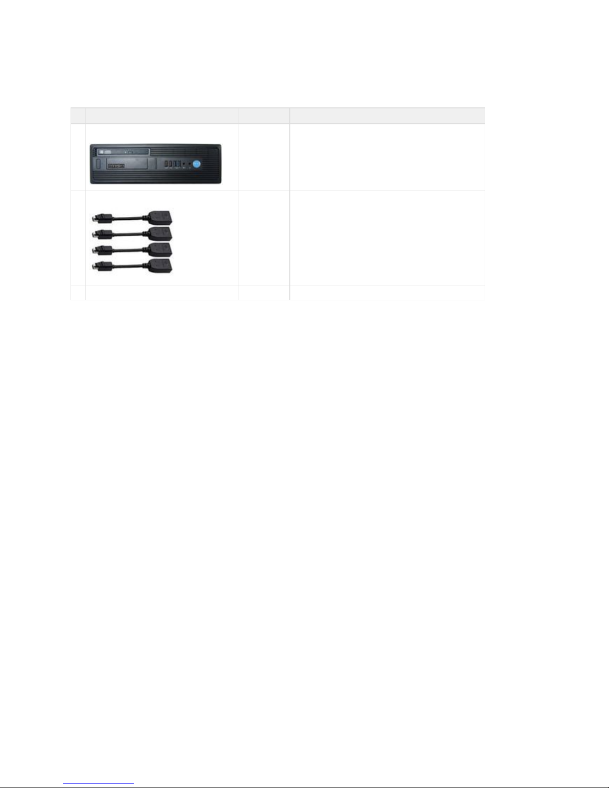
X30 Application Appliance Carton
Kit Part #: 055-00032-00
Prysm 98, Prysm 86, Prysm 85, Prysm 85 Dual, Prysm 65, and Prysm 65 Core.Applies to:
# Item Part Number Notes
1 X30 Application Appliance 055-00032-00 To be installed in the System Cabinet.
4 Locking Mini-DisplayPort to DisplayPort Adapters 781-00178-00 Used to adapt DisplayPort cables to the Mini-DisplayPort ports.
1 Power cable N/A 6 ft. Only used for the Prysm 98.
Page 16
Prysm LCD Visual Workplace Assembly Guide 520-00072-00 Rev 12
16Copyright © 2017, Prysm Inc. All rights reserved. Confidential and proprietary.
Cable Kit Carton
Kit Part #: 050-00348-00
Applies to: Prysm 86, Prysm 85, Prysm 85 Dual, Prysm 65, and Prysm 65 Core
# Cable Length Part
Number
Notes
1 AC Power, 3-Way Splitter Cable, Universal, from C14 to 3x C13,
250V
3 ft 771-00312-00
1 AC Power, NEMA 5-15P to IEC C13, UNIV, 125V, 13A 20 ft 771-00311-00
1 USB 2.0 A-Male to Serial (RS-232) 10 ft 771-00245-00
1 USB 2.0 A-Male to B-Male w/Ferrite 20 ft 771-00305-00 Replaces the 12 ft USB cable in the IIC.
4 HDMI, Male-to-Male, CL2-Rated 20 ft 771-00307-00 One of these replaces the 12 ft HDMI cable in the
IIC.
1 HDMI, Male-to-Male 2 ft 771-00306-00
1 DisplayPort, Male-to-Male with latches 6 ft 771-00308-00
1 CAT6, Male-to-Male RJ45 2 ft 771-00309-00
1 CAT6, Male-to-Male RJ45 20 ft 771-00310-00
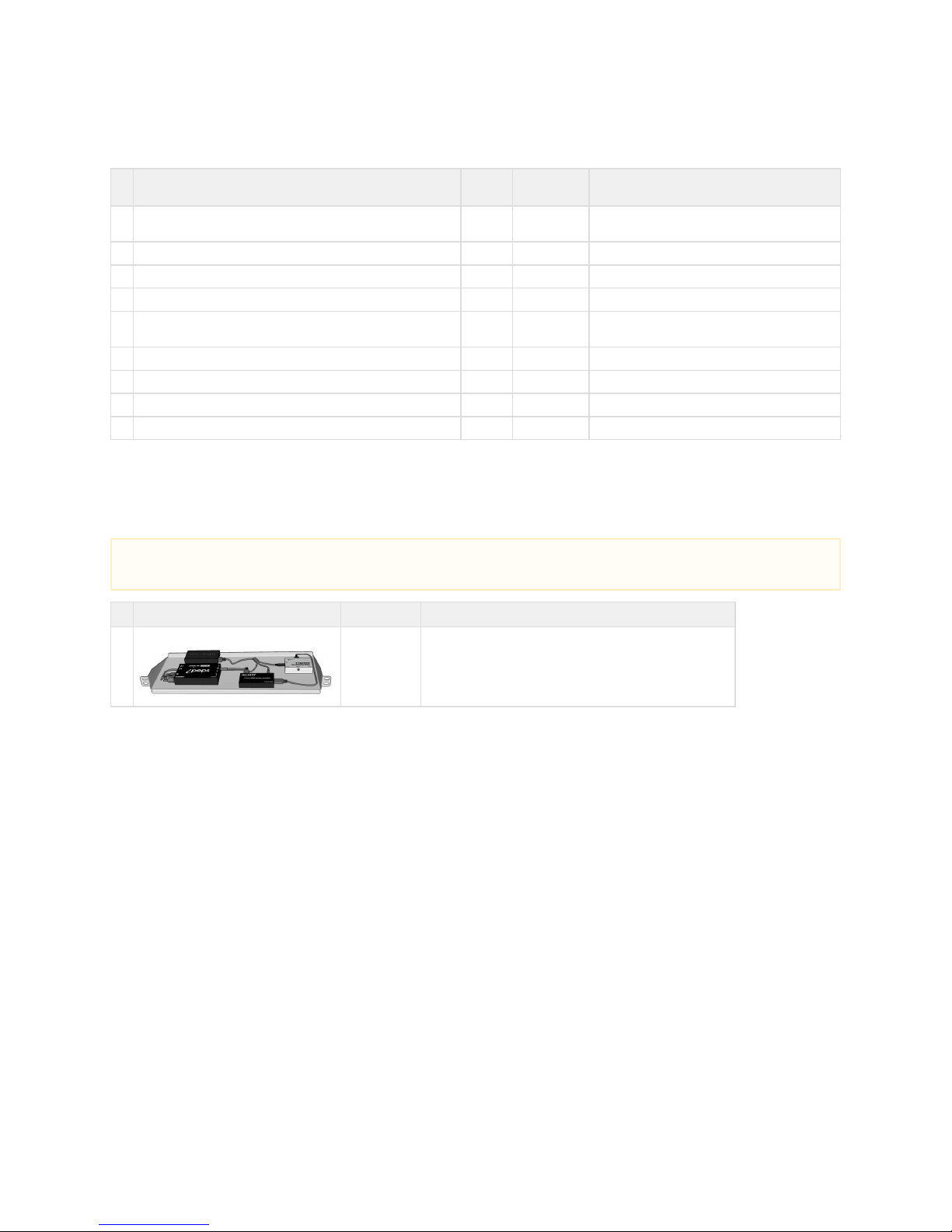
Optional: Interactive Input Controller Carton
Kit Part #: 055-00005-01
Prysm 86, Prysm 85, Prysm 85 Dual, and Prysm 65Applies to:
# Item Part Number Notes
1 Interactive Input Controller
055-00005-01 To be installed in the System Cabinet.
The two coiled cables that come with the IIC will be replaced with
cables from the Cable Kit.
NOTE
The IIC is an optional component and may or may not have been included in the customer order.
Page 17
Prysm LCD Visual Workplace Assembly Guide 520-00072-00 Rev 12
17Copyright © 2017, Prysm Inc. All rights reserved. Confidential and proprietary.
2.2 Product Component Diagrams
Jump to > 2.1 Parts of the Prysm LCD Visual Workplace Stand
2.2.1 Prysm 98 Display
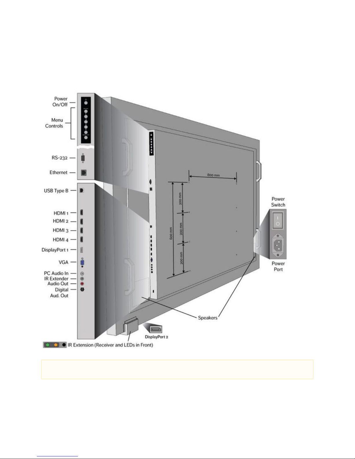
This shows the rear of the Prysm 98 display with the ports, controls, speaker areas, and 8 VESA mounting holes:
Note
Ensure that the plastic covering on the display unit is removed.
Page 18
Prysm LCD Visual Workplace Assembly Guide 520-00072-00 Rev 12
18Copyright © 2017, Prysm Inc. All rights reserved. Confidential and proprietary.
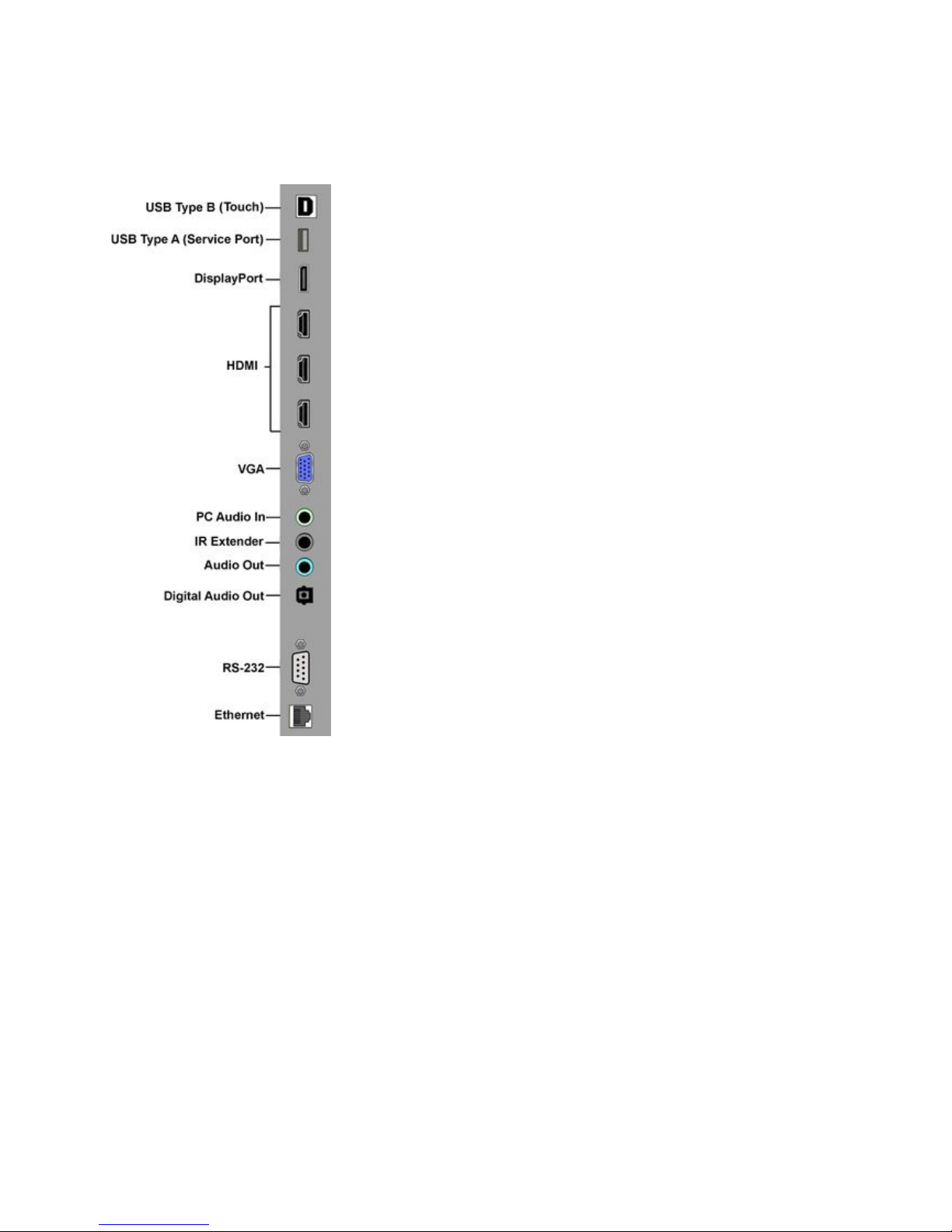
2.2.3 Prysm 86 Display
Similar to the Prysm 85 Display but with a rearrangement of the ports and controls. The port arrangement is shown in the following figure.
(The keypad is below the ports but is the same as the Prysm 85.)
Page 19
Prysm LCD Visual Workplace Assembly Guide 520-00072-00 Rev 12
19Copyright © 2017, Prysm Inc. All rights reserved. Confidential and proprietary.
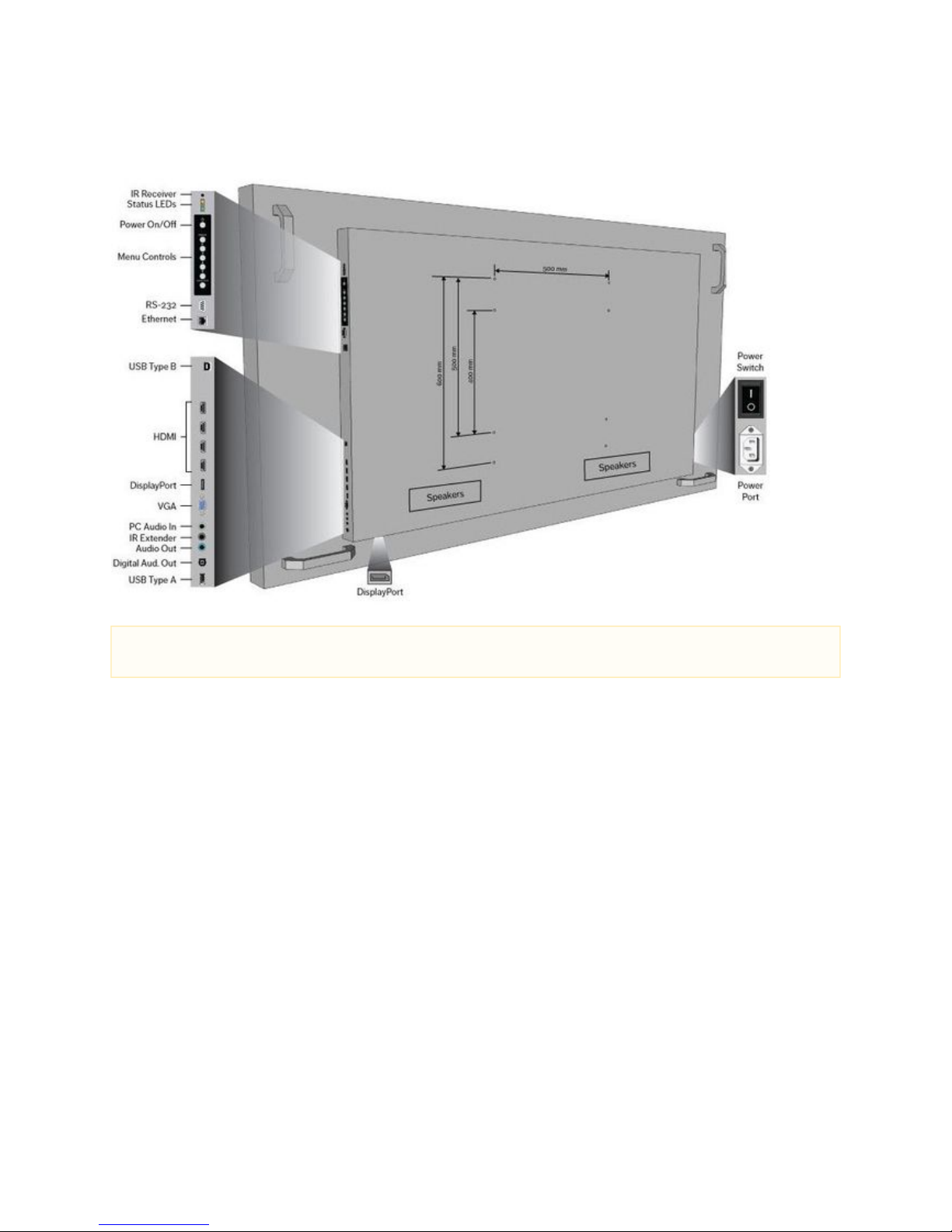
2.2.2 Prysm 85 Display
This shows the rear of the Prysm 85 display with the ports, controls, speaker areas, and 8 VESA mounting holes:
2.2.4 Prysm 84 Display
For a basic diagram of the Prysm 84 and the port locations, see the following image for the Prysm 65.
2.2.4 Prysm 75 Display
For a basic diagram of the Prysm 75 and the port locations, see the following image for the Prysm 65.
Note
Ensure that the plastic covering on the display unit is removed.
Page 20
Prysm LCD Visual Workplace Assembly Guide 520-00072-00 Rev 12
20Copyright © 2017, Prysm Inc. All rights reserved. Confidential and proprietary.
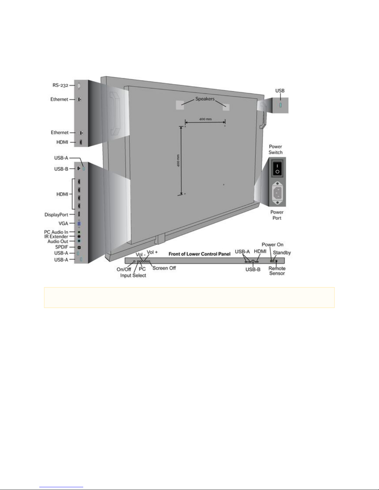
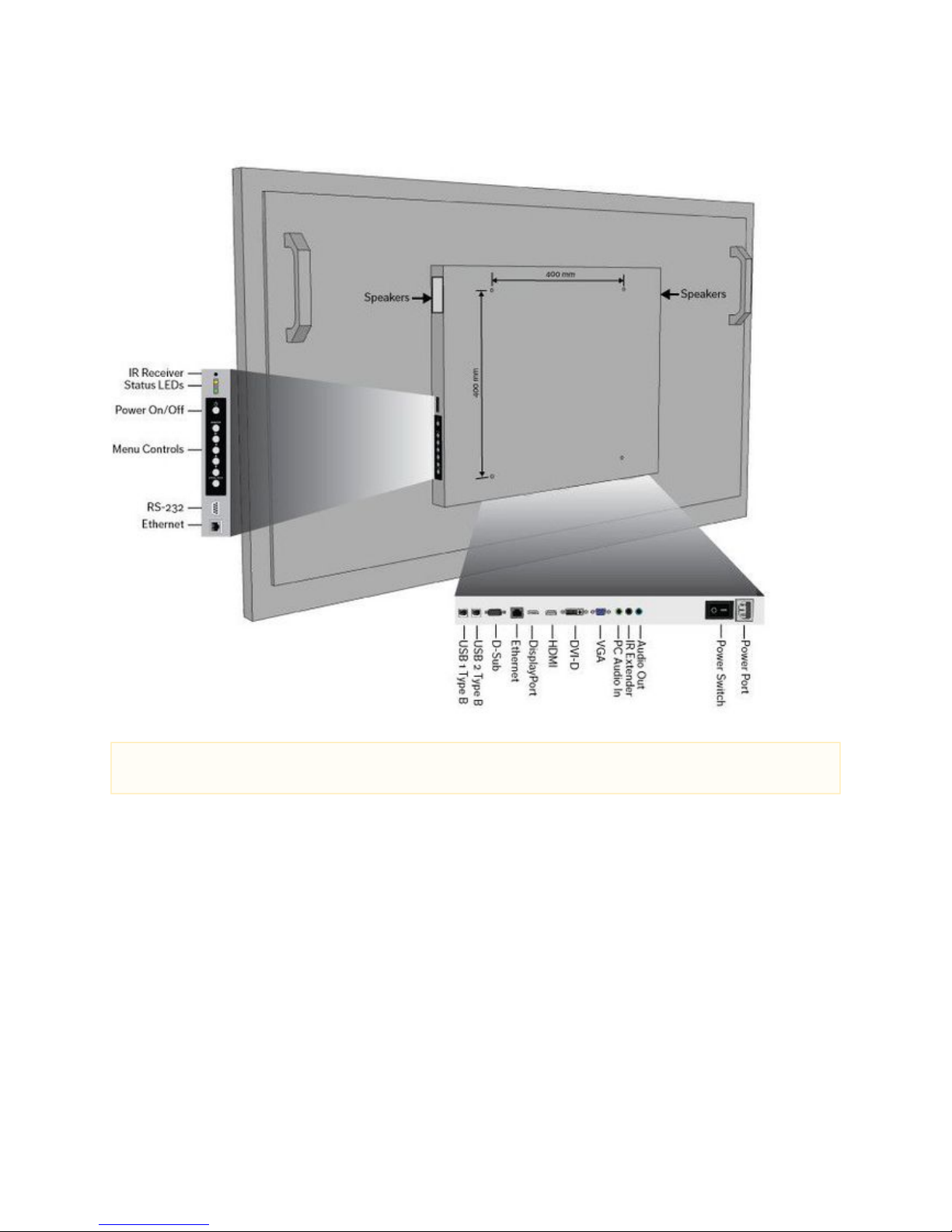
2.2.4 Prysm 65 Display
This shows the rear of the Prysm 65 display with the , and 4 VESA mounting holes. It also shows the controlsports, controls, speaker areas
and ports on the control panel on the lower front of the display:
NOTE:
Ensure that the plastic covering on the display unit is removed.
Page 21
Prysm LCD Visual Workplace Assembly Guide 520-00072-00 Rev 12
21Copyright © 2017, Prysm Inc. All rights reserved. Confidential and proprietary.
2.2.5 Prysm 65 Core Display
This shows the rear of the Prysm 65 Core display with the , and 4 VESA mounting holes:ports, controls, speaker areas
Note
Ensure that the plastic covering on the display unit is removed.
Page 22
Prysm LCD Visual Workplace Assembly Guide 520-00072-00 Rev 12
22Copyright © 2017, Prysm Inc. All rights reserved. Confidential and proprietary.
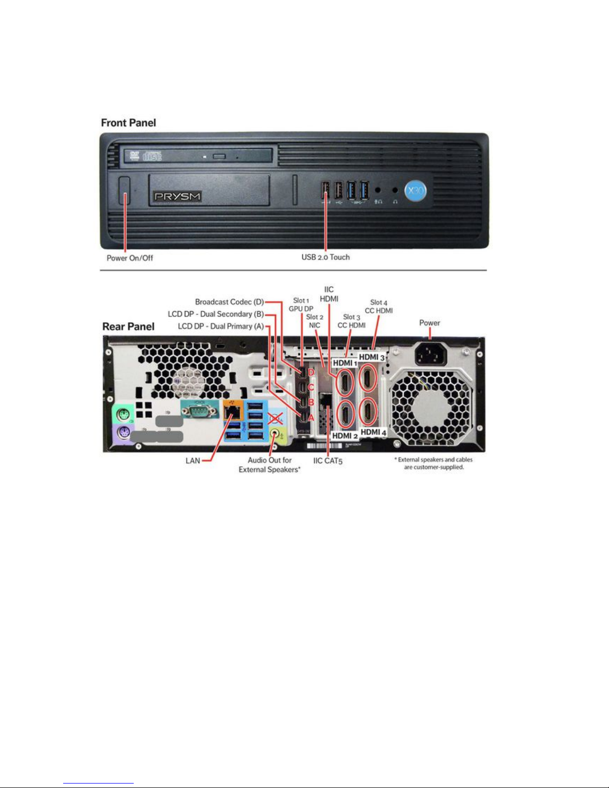
2.2.6 Prysm X30 Application Appliance
The following image shows the front and rear panels of the Prysm X30 Application Appliance with the ports:
Page 23
Prysm LCD Visual Workplace Assembly Guide 520-00072-00 Rev 12
23Copyright © 2017, Prysm Inc. All rights reserved. Confidential and proprietary.
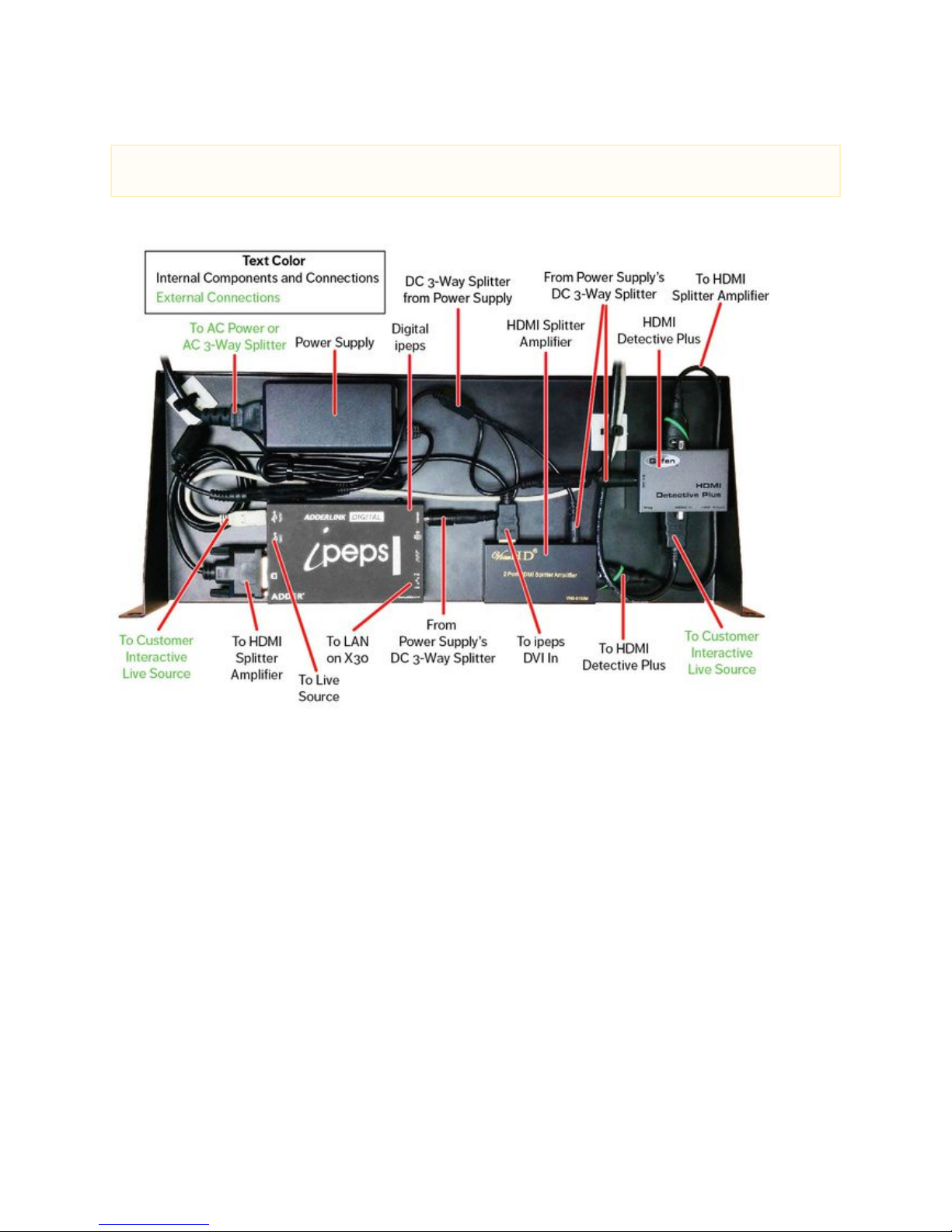
2.2.7 Optional: Interactive Input Controller
The following image shows the Interactive Input Controller, the different components, and the used ports:
NOTE
The IIC is an optional component and may or may not have been included in the customer order.
Page 24

Prysm LCD Visual Workplace Assembly Guide 520-00072-00 Rev 12
24Copyright © 2017, Prysm Inc. All rights reserved. Confidential and proprietary.
3. Assembly Procedures
The following subsections describe the full assembly of all of the Prysm LCD Visual Workplace products. This includes the assembly of the
stand, the installation of the electronic components, installation of the display, and cable connections.
The steps to assemble the components of the Prysm Visual Workplace products are:
3.1 Assemble the Stand
3.2 Install the Display Support Assembly
3.3 Install the Camera Support
3.4 Install the System Cabinet
3.5 Set up the System Components
3.6 Install the Display
3.7 Install the Keyboard Shelf
3.8 Apply the Labels
NOTE
The Prysm 98 does not come with a stand or Interactive Input Controller (IIC). There are no instructions in this guide for mounting
the display, but the cabling diagram for the display, and the X30 Application Appliance, can be found in the separate product
sections of .4. Cabling Procedures
Page 25
Prysm LCD Visual Workplace Assembly Guide 520-00072-00 Rev 12
25Copyright © 2017, Prysm Inc. All rights reserved. Confidential and proprietary.
1.
2.
3.
a.
b.
3.1 Assemble the Stand
Jump to > 2.1 Parts of the Prysm LCD Visual Workplace Stand
# of Installers
Minimum of two
Tools
Utility knife or boxcutter
17 mm and 20 mm open end wrenches
6 mm hex wrench (comes with stand in polybag)
#2 Phillips screw driver
Parts from Stand carton
1 Stand Base with Casters
2 Support Columns
2 Center Support (for Keyboard Tray)
Parts from Open Me First carton
4 Leveling Feet 773-01358-00
2 Extra Column Slot Inserts 773-01359-00
Hardware
8 M8 x 25 mm Hex Cap screws From Stand carton
(A2 section of polybag)
3.1.1 Instructions
Cut strapping on the Prysm LCD Visual Workplace stand (032-000017-01) carton and open the carton.
Remove bags of hardware. Save only the long M8 screws and the two hex wrenches.
Replace the four Casters on the Base with the Leveling Feet.
Use a 17 mm open end wrench to remove the Casters.
Use a 20 mm open end wrench to install the Leveling Feet.
NOTE
There are two stands for the Prysm 85 Dual product. Assemble both stands following these instructions. Cabling for the Prysm 85
Dual has only a few extra cables, described in .Step 4.3 Cable the Prysm 85 Dual
NOTE
The Prysm 98 is wall-mounted and does not come with a stand. Ignore all stand and cabinet installation procedures and move
directly to the cabling instructions in .4.1 Cable the Prysm 98
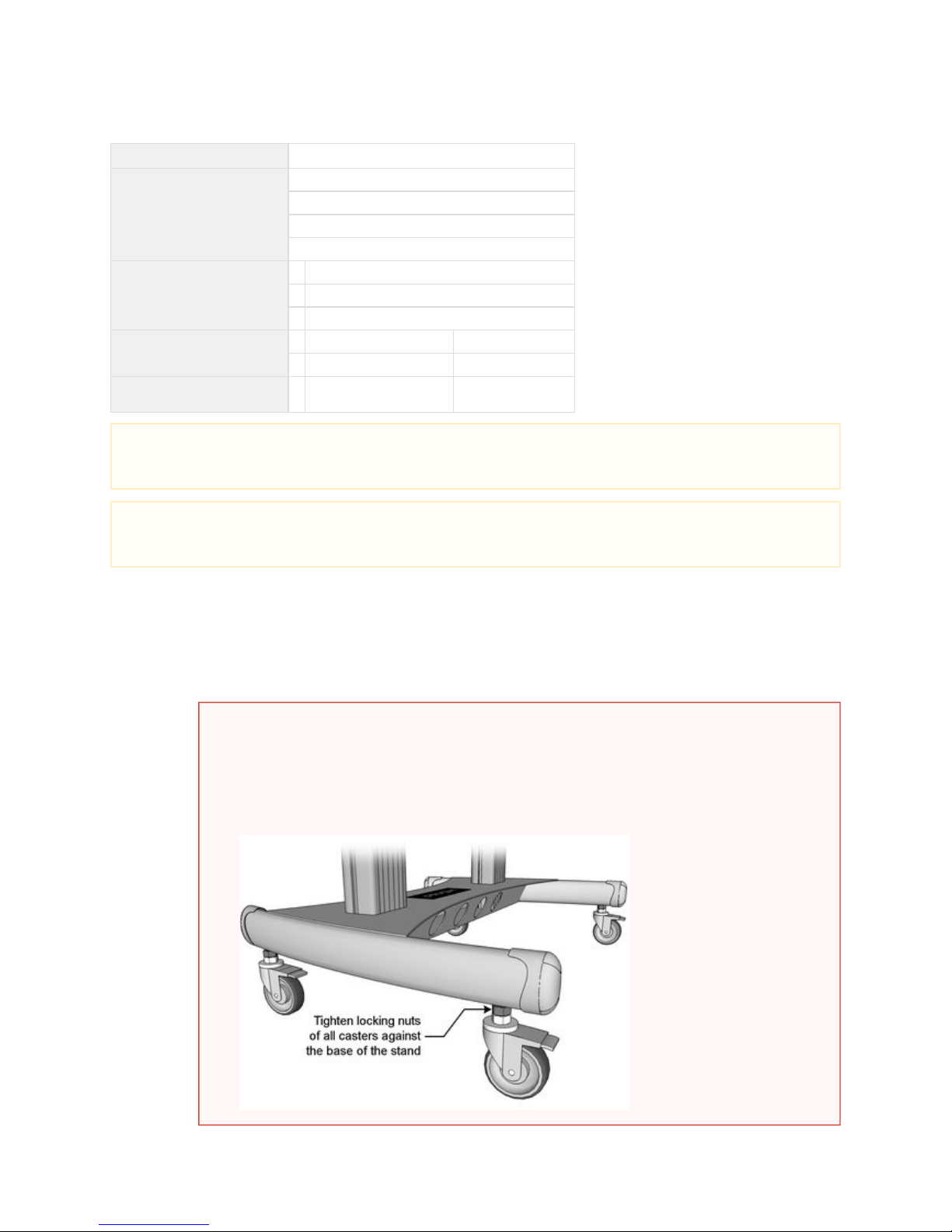
WARNING
This assembly guide emphasizes the use of adjustable feet over the use of casters, but some customers want
the display stand to be easily moveable and request that the casters be used. There is a safety issue if the
casters are not tightened securely to the base of the display stand. The threaded rods can bend and the display
stand can tip over.
To make sure this doesn't happen, use a 17mm open end wrench to tighten the upper nuts (lock nuts) on the
threaded rod of the casters to the base of the display stand. No part of the threaded rod should show.
Page 26
Prysm LCD Visual Workplace Assembly Guide 520-00072-00 Rev 12
26Copyright © 2017, Prysm Inc. All rights reserved. Confidential and proprietary.
4.
5.
6.
7.
8.
a.
b.
To install the Support Columns to the Base, tip Base onto one of the long sides with one installer holding it upright.
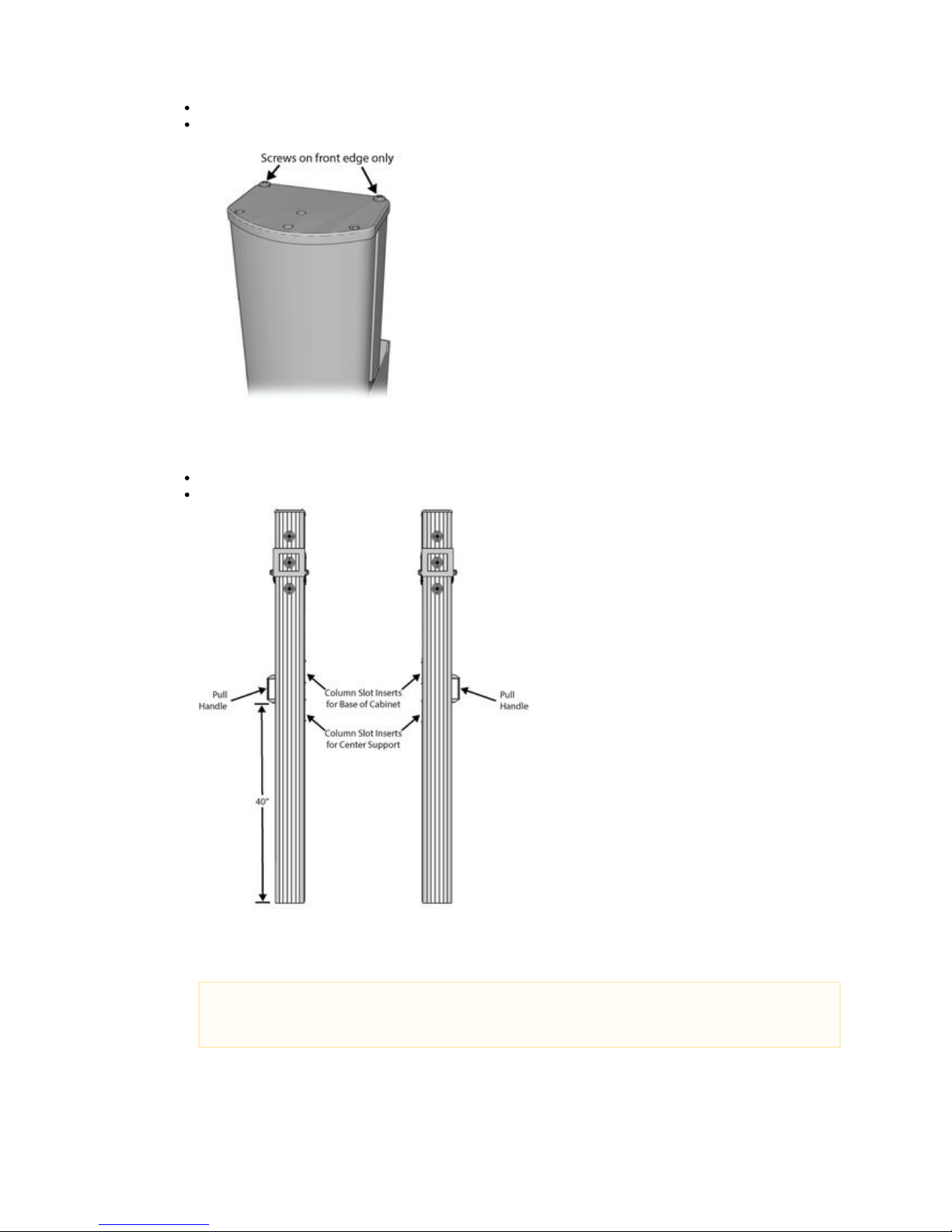
Make sure the Cap at the top of each Support Column is held in place by two screws.
Make sure the screws are on the front (grommet) side of each column.
Leave the holes on the rounded edge empty.
Make sure the Pull Handles are positioned so the lower edges are 40 inches up from the bottom edge of the columns. If not, loosen
the screws on the handles so you can slide them in the slot. Move them into position and tighten the screws with a #2just enough
Phillips screwdriver.
For each column, slide one Column Slot Insert up from the bottom of the inner slot, just under the pre-installed insert.
Make sure the tabs face out from the slot and the hole is at the top.
There should now be two Column Slot Inserts in each Support Column as shown below:
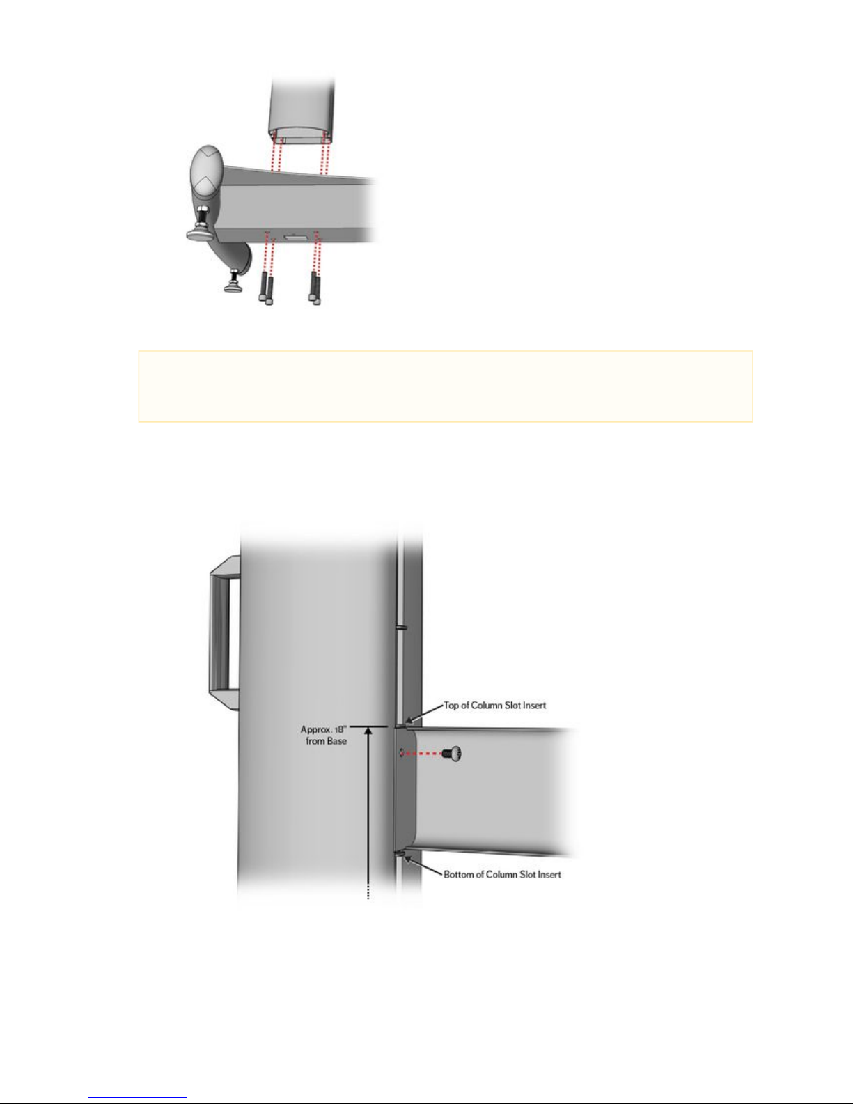
Install one of the Support Columns by fitting the lower end into one of the holes in the Base so that the Handle is on the outside.
Use a 6 mm hex wrench (from B2 section of polybag) to connect the columns to the Base with four M8 hex cap screws
(from A2 section of polybag).
Make sure the column is square to the base and the four screws are very tight.
NOTE
At this point, take note of the holes in the Base at the bottom of the columns. This is where cables will be fed out
of the stand.
Page 27
Prysm LCD Visual Workplace Assembly Guide 520-00072-00 Rev 12
27Copyright © 2017, Prysm Inc. All rights reserved. Confidential and proprietary.
9.
10.
11.
a.
b.
c.
d.
e.
f.
Install the other Support Column in the same way.
Lift the stand into the upright position.
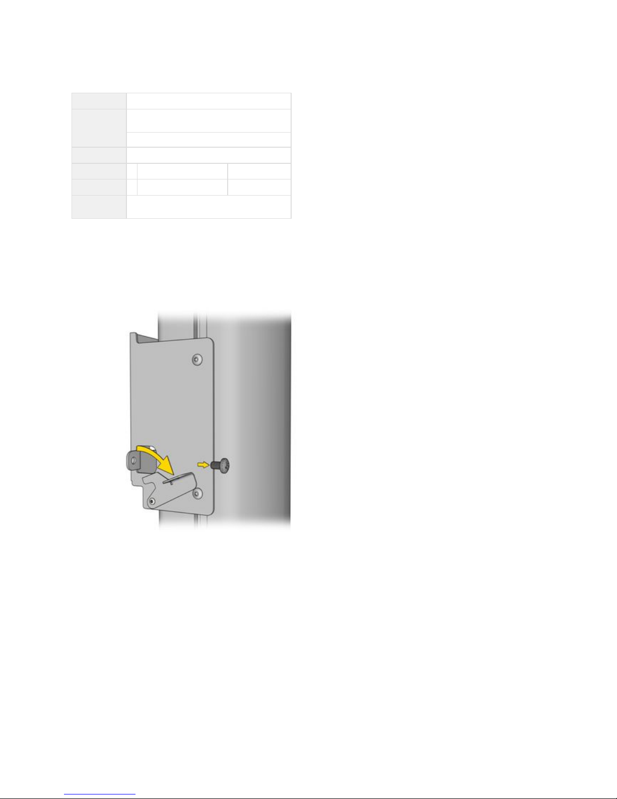
Install the Center Support onto the two Column Slot Inserts with the open side facing the back of the stand, as follows:lower
Remove the screws that came pre-attached to two of the Column Slot Inserts.
Position the two lower Column Slot Inserts level to each other, so the tops are about 18 inches from the Base. (Can be
repositioned later, after the display is installed.)
Slip one end of the Support Column between the tabs on an Insert.
Fit the other end between the tabs of the opposite Insert.
Hold the Center Support loosely in place with the two screws taken from the upper Column Slot Inserts.
Square the Center Support to the columns and tighten the screws with a #2 Phillips screw driver.
NOTE
The Center Support spans the two Support Columns giving added rigidity to the stand. Do not leave out this part. It can
also be used as the support for the keyboard tray, if the customer wants it. If not, the Center Support can be moved to be
just up behind the lower edge of the display, out of view.
Page 28
Prysm LCD Visual Workplace Assembly Guide 520-00072-00 Rev 12
28Copyright © 2017, Prysm Inc. All rights reserved. Confidential and proprietary.
1.
3.2 Install the Display Support Assembly
Jump to > 2.1 Parts of the Prysm LCD Visual Workplace Stand
# of Installers
One
Tools
5 mm hex wrench
(From Stand carton in polybag)
#2 Phillips screw driver
Parts
Display Stand as currently assembled
1 Camera Support Connector From Stand carton
1 Display Support Plate From Stand carton
Hardware
Screws pre-installed in the
Camera Support Connector
3.2.1 Instructions
Install the Display Support Plate as follows:
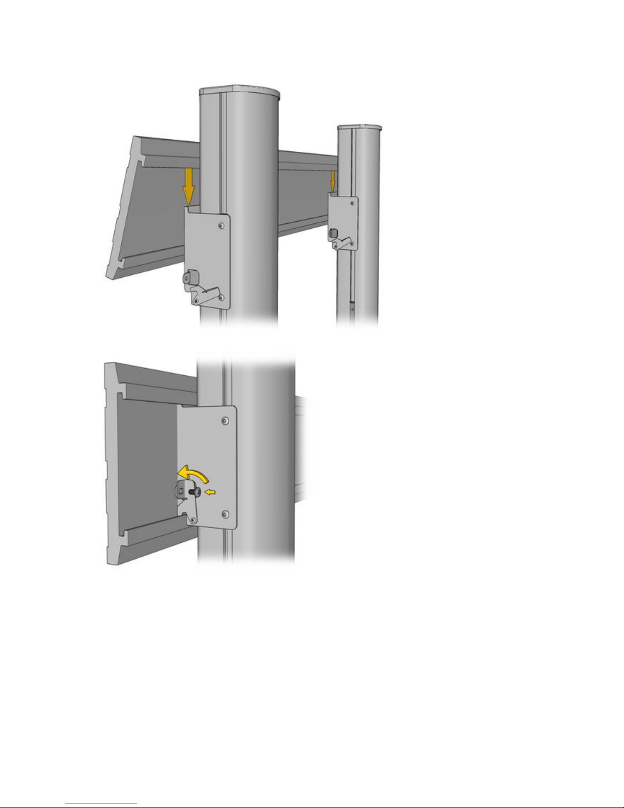
With a #2 Phillips screw driver, remove the screws from all four Display Support Plate Locks on the Display Height Brackets and tilt
the locks back. Save the screws to replace later.
Page 29
Prysm LCD Visual Workplace Assembly Guide 520-00072-00 Rev 12
29Copyright © 2017, Prysm Inc. All rights reserved. Confidential and proprietary.
2.
3.
4.
Center the Display Support Plate with the two Display Height Brackets before you snap it into position.
Once the plate is centered, press down hard on the top edge until it snaps onto the Display Height Brackets.
Rotate each Display Support Plate Lock back into position and reinstall the screws with a #2 screw driver.
Page 30
Prysm LCD Visual Workplace Assembly Guide 520-00072-00 Rev 12
30Copyright © 2017, Prysm Inc. All rights reserved. Confidential and proprietary.
5.
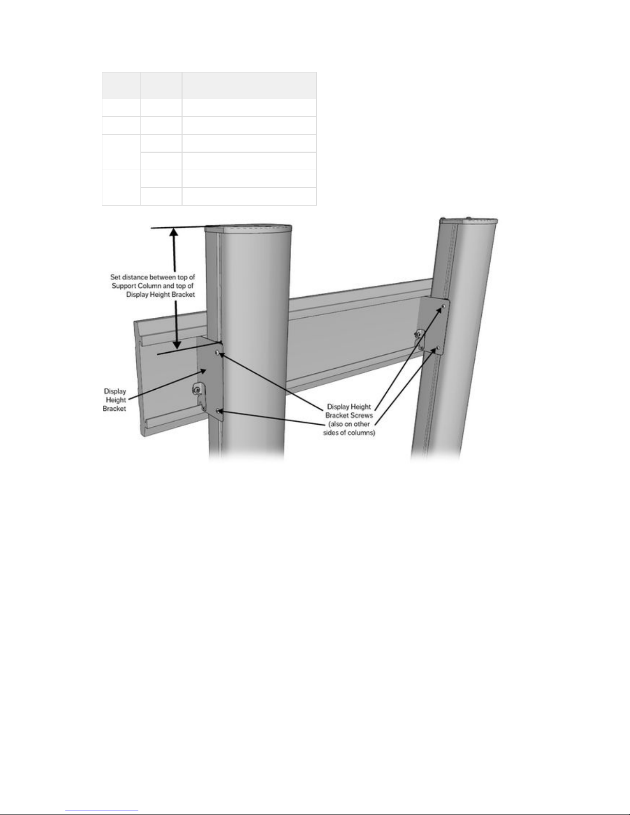
6.
With a 5 mm hex wrench, loosen all 8 screws on the Display Height Brackets and set the distance between the tops of the Support
Columns and the tops of the Display Height Brackets as follows:
Display
Size
Feet or
Casters
Set the Display Height Bracket
To Support Column Cap Distance
86" Feet Try 9" and adjust as necessary
Casters Try 12" and adjust as necessary
85" Feet 13"
Casters 10"
65" Feet 12"
Casters 15"
Tighten screws on Display Height Brackets.
Page 31
Prysm LCD Visual Workplace Assembly Guide 520-00072-00 Rev 12
31Copyright © 2017, Prysm Inc. All rights reserved. Confidential and proprietary.
1.
a.
b.
c.
d.
e.
f.
g.
h.
3.3 Install the Camera Support
Jump to > 2.1 Parts of the Prysm LCD Visual Workplace Stand
# of Installers
One or two
Tools
#2 Phillips screw driver
Parts
Display Stand as currently assembled
1 Camera Support Platform From Stand carton
1 Camera Support Bar From Stand carton
Screws attached
1 Camera Support Connector From Stand carton (two parts)
Screws attached
3.3.1 Instructions
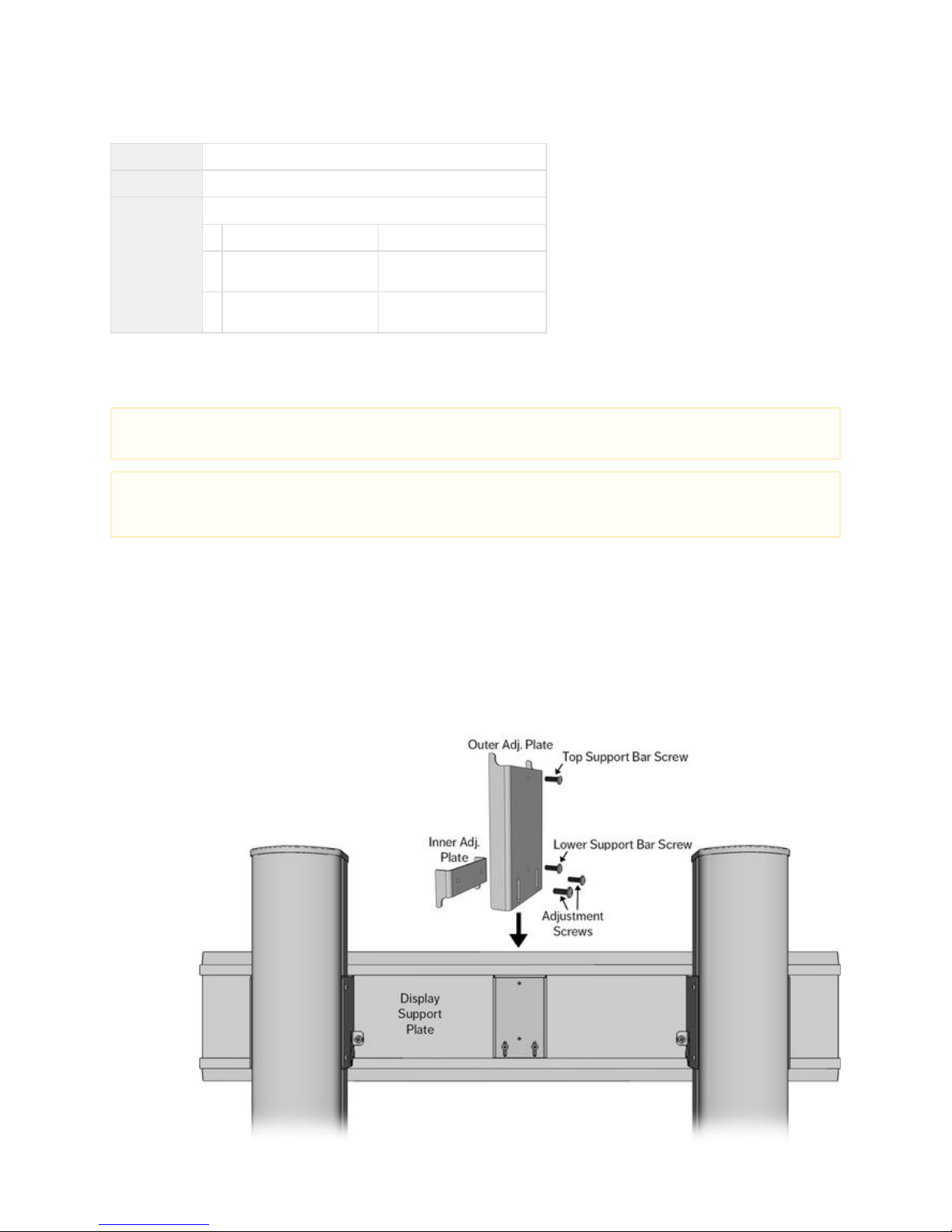
To install the Camera Support Connector to the rear of the Display Mounting Plate:
With a #2 Phillips screw driver, remove the Top Support Bar Screw and set aside for installing the Support Bar.
Unscrew the Lower Support Bar Screw until just before the screw comes out.
Slightly loosen the left and right Adjustment Screws (in slotted holes) that attach the two plates to each other so they will
slide apart.
Fit the plates into the rear of the Display Support Plate so that the top of the outer plate fits into the upper groove of the
support plate and the bottom of the inner plate fits into the lower groove of the support plate.
Making sure the connector is centered, hold the outer plate up into the upper groove so that the two plates are fully
separated.
Instead of tightening the two adjustment screws (which will make the Inner Adjustment Plate rise up slightly), screw in the
Lower Support Bar Screw over the top of the Inner Adjustment Plate.
Tighten the Adjustment Screws all the way.
Remove the Lower Support Bar Screw and set aside with the Upper Support Bar Screw.
NOTE
The Camera Support assembly should be installed before the System Cabinet is installed.
IMPORTANT
The Camera Support Connector must be installed in a specific way so that the lower of the two center screws does not run up
against the Inner Adjustment Plate. Follow these instructions exactly, using the illustration as a guide to the part names.
Page 32
Prysm LCD Visual Workplace Assembly Guide 520-00072-00 Rev 12
32Copyright © 2017, Prysm Inc. All rights reserved. Confidential and proprietary.
2.
a.
b.
c.
3.
a.
b.
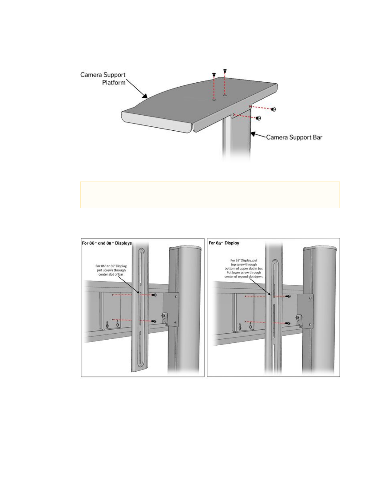
To assemble the Camera Support:
Use a #2 Phillips screw driver to remove the 4 screws from the top part of the Camera Support Bar.
Place the Camera Support Platform on top of the bar.
Reinsert and tighten the screws.
To install the Camera Support:
Place the Camera Support Bar against the Camera Support Connector plate so that the slots in the bar align with the
vertically-aligned screw holes in the connector plate, as shown:
Replace and tighten the screws removed earlier from the plate.
NOTE
The height setting for the Camera Mount depends on the size of the display. Use the following settings based on
screw placement within the slots of the support bar.
Page 33
Prysm LCD Visual Workplace Assembly Guide 520-00072-00 Rev 12
33Copyright © 2017, Prysm Inc. All rights reserved. Confidential and proprietary.
1.
3.4 Install the System Cabinet
Jump to > 2.1 Parts of the Prysm LCD Visual Workplace Stand
# of Installers
Two
Tools
Socket wrench with 13 mm (or ½") socket
4 mm hex wrench
#2 Phillips screw driver
Parts
Display stand as currently assembled
1
System Cabinet (Cabinet Shelf and Cover)
050-00330-01 From Cabinet carton
Hardware
2
Self-tapping / " flange bolts with ½" hex cap
5
16
From Cabinet carton773-01918-00
2 M6 flanged socket cap screws 773-01267-00 From Cabinet carton
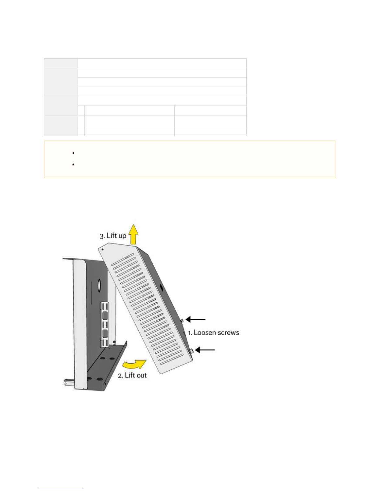
3.4.1 Instructions
Remove the cover from the System Cabinet shelf by unscrewing the two captive screws at the base of the cover, then lifting out
and up.
NOTES
For the Prysm 85 Dual with two stands, you will install a System Cabinet and all contained components only on the
Primary Stand.
The Prysm 98 does not come with a stand. For the Prysm 98, ignore all stand and cabinet installation procedures and
move directly to the cabling instructions in 4.1 Cable the Prysm 98.
Page 34
Prysm LCD Visual Workplace Assembly Guide 520-00072-00 Rev 12
34Copyright © 2017, Prysm Inc. All rights reserved. Confidential and proprietary.
2.
3.
4.
5.
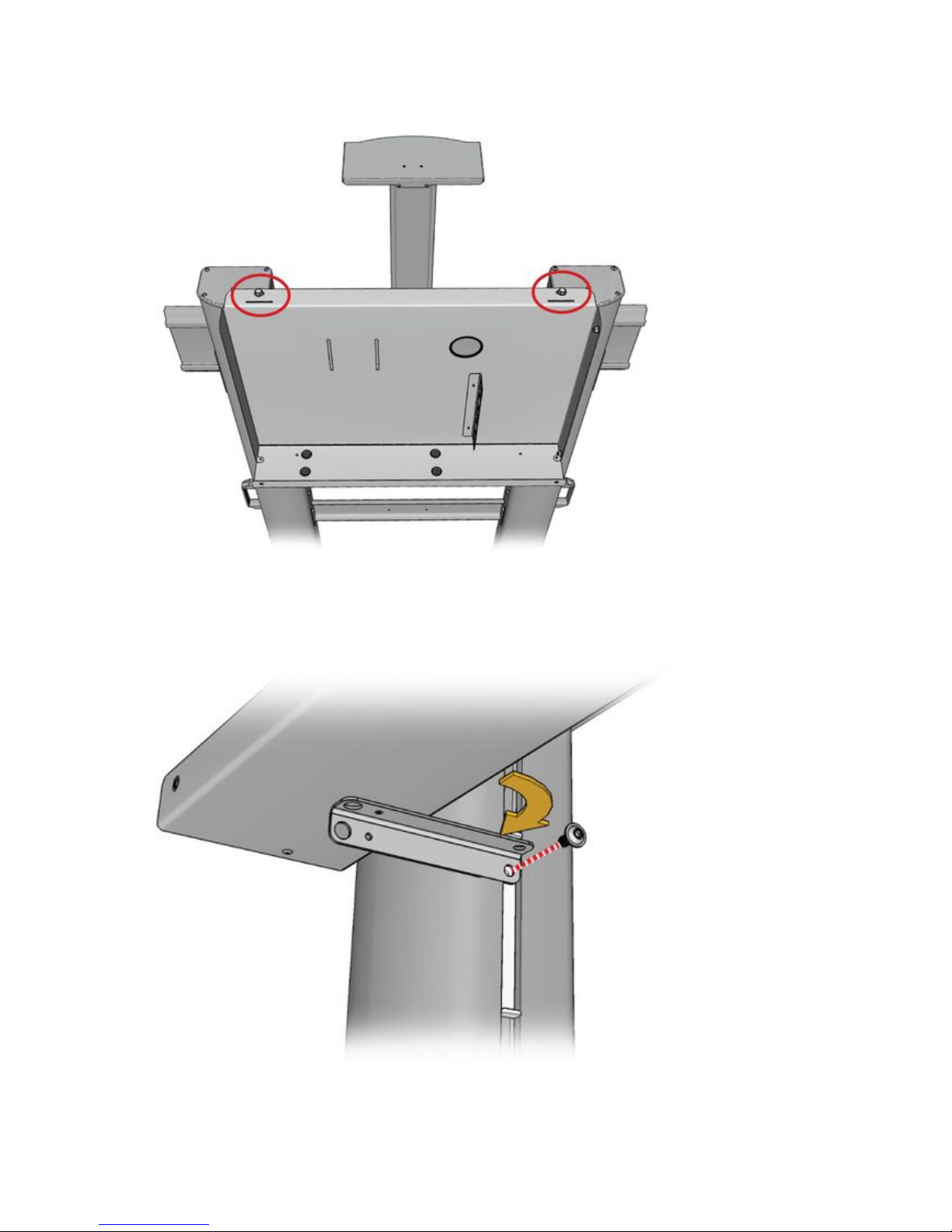
Lift the Cabinet Shelf onto the rear of the stand and hang the lip at the top edge over the two Support Column caps. Align the holes
in each end of the lip with the corner holes in the
Column Caps. With one person holding the cabinet in place, the other person can install a self-tapping 5/16" flange bolts with ½" cap
into the top of each hole using a 13 mm or ½” socket wrench.
Pivot one of the two out from beneath the cabinet and align the hole with the hole at the top of the Support Brackets upper-most
Column Slot Insert.
Connect the to the Column Slot Insert with one of the M6 flanged socket cap screws using a 4 mm hex wrench.Support Brackets
Tighten the screw until the does not move in the slot. Column Slot Insert
Repeat this procedure with the Support Bracket on the other side.
Page 35
Prysm LCD Visual Workplace Assembly Guide 520-00072-00 Rev 12
35Copyright © 2017, Prysm Inc. All rights reserved. Confidential and proprietary.
1.
2.
3.
4.
3.5 Set up the System Components
Jump to > 2.1 Parts of the Prysm LCD Visual Workplace Stand
# of Installers
One
Tools
10 mm socket wrench
Parts
Display stand as currently assembled
1 System Cabinet
with Z-Bracket and Z-Bracket Base Plate
050-00330-01
1 Prysm Application ApplianceX30 055-00032-00
From Prysm ApplicationX30
Appliance carton
1 Interactive Input Controller
(not offered with the Prysm 98 or Prysm 65 core)
055-00005-01
From Interactive Input
Controller carton
Hardware
4 utsM6 lockn 773-01267-00
From X30 Prysm Application
Appliance carton
3.5.1 Instructions
If the cabinet cover is in place, remove it by unscrewing the two captive screws at the base of the cover, then lifting out and up.
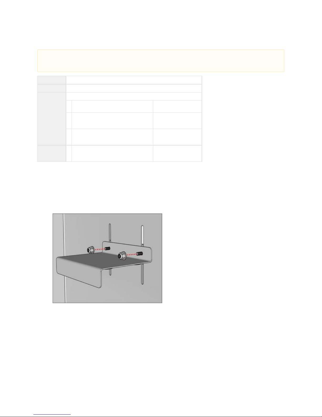
Reaching up between the display and the cabinet, feed the threaded posts of the Z-Bracket Base Plate through the two slots in the
cabinet so the posts appear inside the cabinet.
Fit the Z-Bracket to the posts on the inside of the cabinet so that the flange points downward (posts at top).
Holding the base plate from the other side of the cabinet, fit the two posts inside the cabinet with two loosely M6 locknuts, as shown:
NOTE
The height setting for the Camera Mount depends on the size of the display. Use the following settings based on screw placement
within the slots of the support bar.
Page 36
Prysm LCD Visual Workplace Assembly Guide 520-00072-00 Rev 12
36Copyright © 2017, Prysm Inc. All rights reserved. Confidential and proprietary.
5.
6.
7.
8.
9.
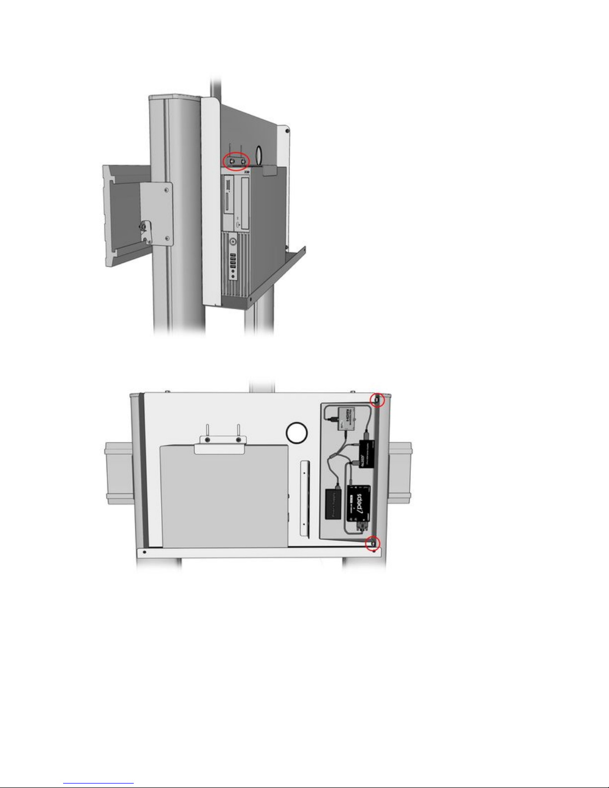
Install the Prysm Application Appliance by setting it in the cabinet with the front panel facing to the left and the top facingX30
you. Center the X30 over the 4 rubber pads on the bottom of the shelf.
Slide the Z-Bracket down over the X30, and tighten the Nylock nuts with a 10 mm socket wrench.
If the customer order includes an Interactive Input Controller (does not come standard), install by fitting the tray into the right side of
cabinet so that two of the mounting holes go over the threaded posts on the side of the cabinet.the
Screw two onto the threaded posts and tighten with a 10 mm socket wrench. M6 locknuts
Reinstall the cover on the Cabinet Shelf.
Page 37
Prysm LCD Visual Workplace Assembly Guide 520-00072-00 Rev 12
37Copyright © 2017, Prysm Inc. All rights reserved. Confidential and proprietary.
1.
2.
3.
4.
5.
6.
3.6 Install the Display
Jump to > 2.1 Parts of the Prysm LCD Visual Workplace Stand
# of Installers to set up the display
One
# of Installers to lift the display
Minimum of four
Tools
6 mm hex wrench
#2 Phillips screw driver
Parts
Display stand as currently assembled
1 Display (one of the following:) 86" - 030-00076-00
85" - 030-00043-00
(There are two 85" displays with the Prysm 85 dual)
65" - 030-00042-00
65" Core - 030-00054-00
2 Display Hook Brackets Comes with stand
Hardware
8
8
8
Hook Bracket Attachment Hardware:
M8 hex cap screws
flat washers
lock washers
From the Open Me First carton
773-00888-16
773-00738-00
773-00190-00
3.6.1 Instructions
Make sure the display height setting has been made to the Stand (see ).3.2 Install the Display Support Assembly
Cut the strapping on the display carton, remove the white plastic tabs near the bottom of the box, and lift off the top of the box.
Leave the display upright in the lower section of the box.
Untape the plastic bag, and pull it down around the display.
Remove any plastic film taped to the back of the display.
Remove all of the screws and washers from the VESA holes and discard them.
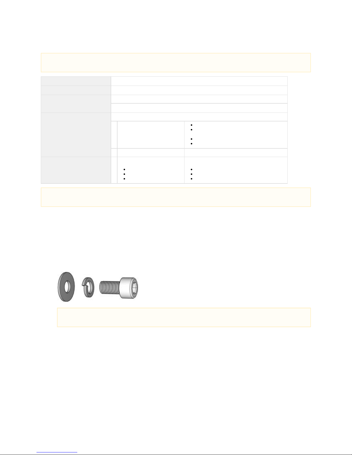
For each M8 hex cap screw used, first slip a lock washer, then a flat washer, onto the screw shaft.
IMPORTANT
The following instructions do not apply to the Prysm 98 which is a wall-mounted display.
NOTE
There are two displays for the Prysm 85 Dual product. Install a display on each stand following these instructions.
NOTE
You will use 4 to 6 screw sets for the 86" and 85" display and 4 screw sets for the 65" displays.
Page 38
Prysm LCD Visual Workplace Assembly Guide 520-00072-00 Rev 12
38Copyright © 2017, Prysm Inc. All rights reserved. Confidential and proprietary.
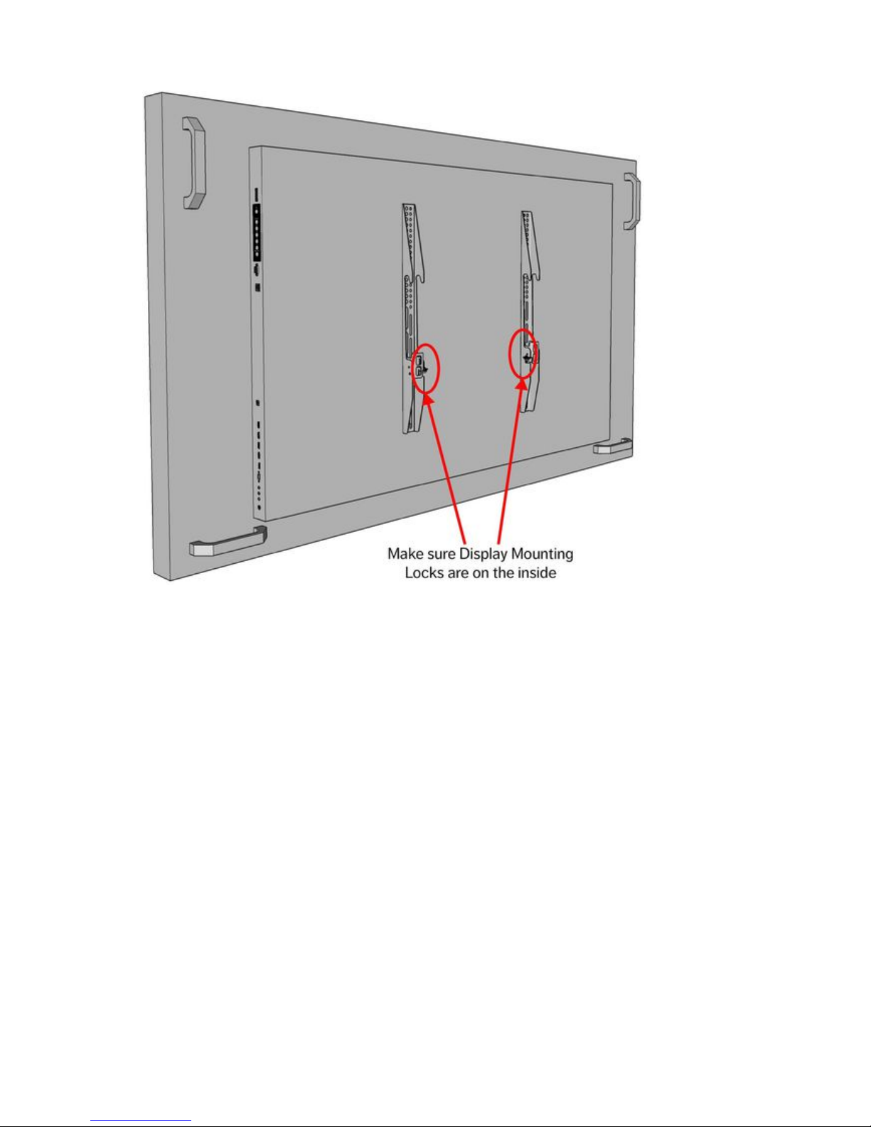
7. Orient the Display Hook Brackets on the rear of the display so that the holes (not slots) are at the top and the Display Mounting Plate
Locks are on the inside.
Page 39
Prysm LCD Visual Workplace Assembly Guide 520-00072-00 Rev 12
39Copyright © 2017, Prysm Inc. All rights reserved. Confidential and proprietary.
8.
a.
b.
c.
9.
a.
b.
c.
10.
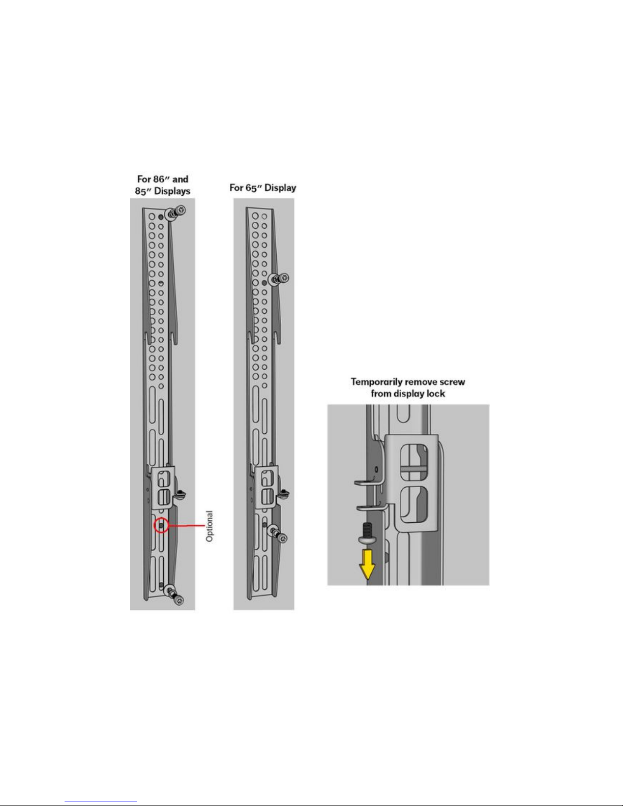
Install the Display Hook Brackets - 86" and 85" display:
Using a 6 mm hex wrench, install a screw (with spring and flat washers) through the smaller top hole in the bracket and
mount it into the top VESA hole in the display.
Install another screw through the lowest thin slot of the bracket into the lowest VESA hole in the display.
(For extra security, you can install a third screw through the second thin slot from the bottom of the bracket into the second
VESA hole up in the display.)
Tighten the screws.
Install the Display Hook Brackets 65" and 65" Core display: -
Using a 6 mm hex wrench, install a screw (with spring and flat washers) through the smaller eighth hole down in the bracket
and into the top VESA hole in the display.
Install another screw through the second thin slot from the bottom into the lowest VESA hole in the display.
Tighten the screws.
With a #2 Phillips screw driver, remove the screw on the Display Lock on both Display Hook Brackets, as shown above. Keep the
screws to reinstall later.
Page 40
Prysm LCD Visual Workplace Assembly Guide 520-00072-00 Rev 12
40Copyright © 2017, Prysm Inc. All rights reserved. Confidential and proprietary.
11.
12.
13.
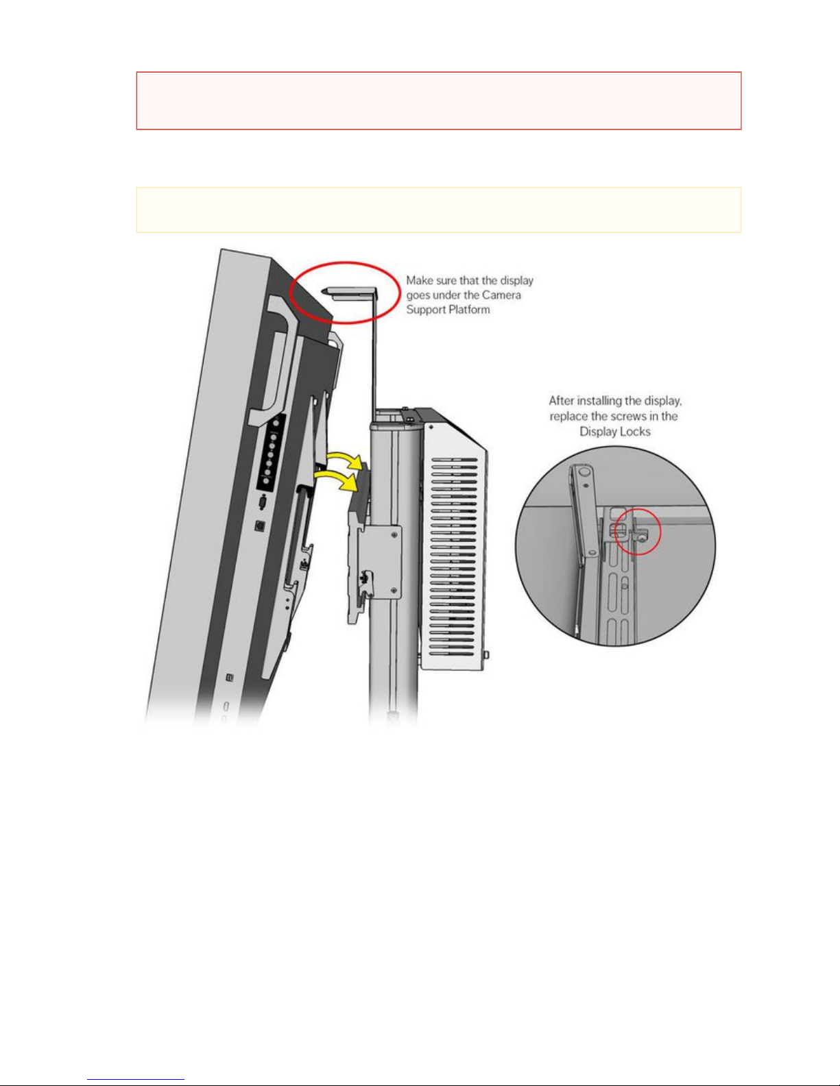
Lift the display up to the Display Support Plate on the Prysm stand and hook the hooks over the top edge of the plate. Center the
display on the plate.
With a #2 Phillips screw driver, lock the display onto the Display Support Plate by lifting up the Display Mounting Plate Locks on
each Display Hook Bracket and replacing the screws removed earlier. Tighten screws.
At this point, the keyboard shelf can be repositioned so that the surface of the shelf is about 10 inches below the lowest edge of the
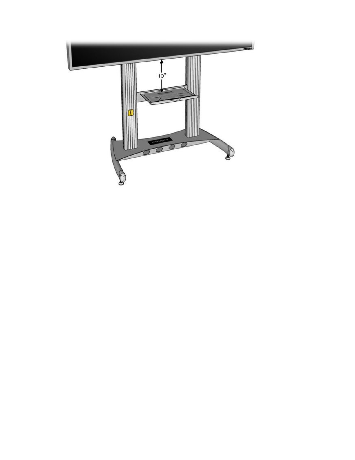
display. To do this, loosen the two screws holding the Center Support, move to desired height, and retighten the screws.
CAUTION
Be aware of the Camera Mount when installing the display. Ensure that the top edge of the display does not hit the
Camera Platform.
NOTE
Make sure the plastic hook covers that are snapped onto the hooks do not come off while installing the display.
Page 41
Prysm LCD Visual Workplace Assembly Guide 520-00072-00 Rev 12
41Copyright © 2017, Prysm Inc. All rights reserved. Confidential and proprietary.
1.
2.
3.
4.
3.7 Install the Keyboard Shelf
Jump to > 2.1 Parts of the Prysm LCD Visual Workplace Stand
# of Installers
One
Tools
#2 Phillips screw driver
Parts
1 Keyboard Shelf From Stand carton
with attached screws
1 Plastic Wrist Rest From Stand carton
3.7.1 Instructions
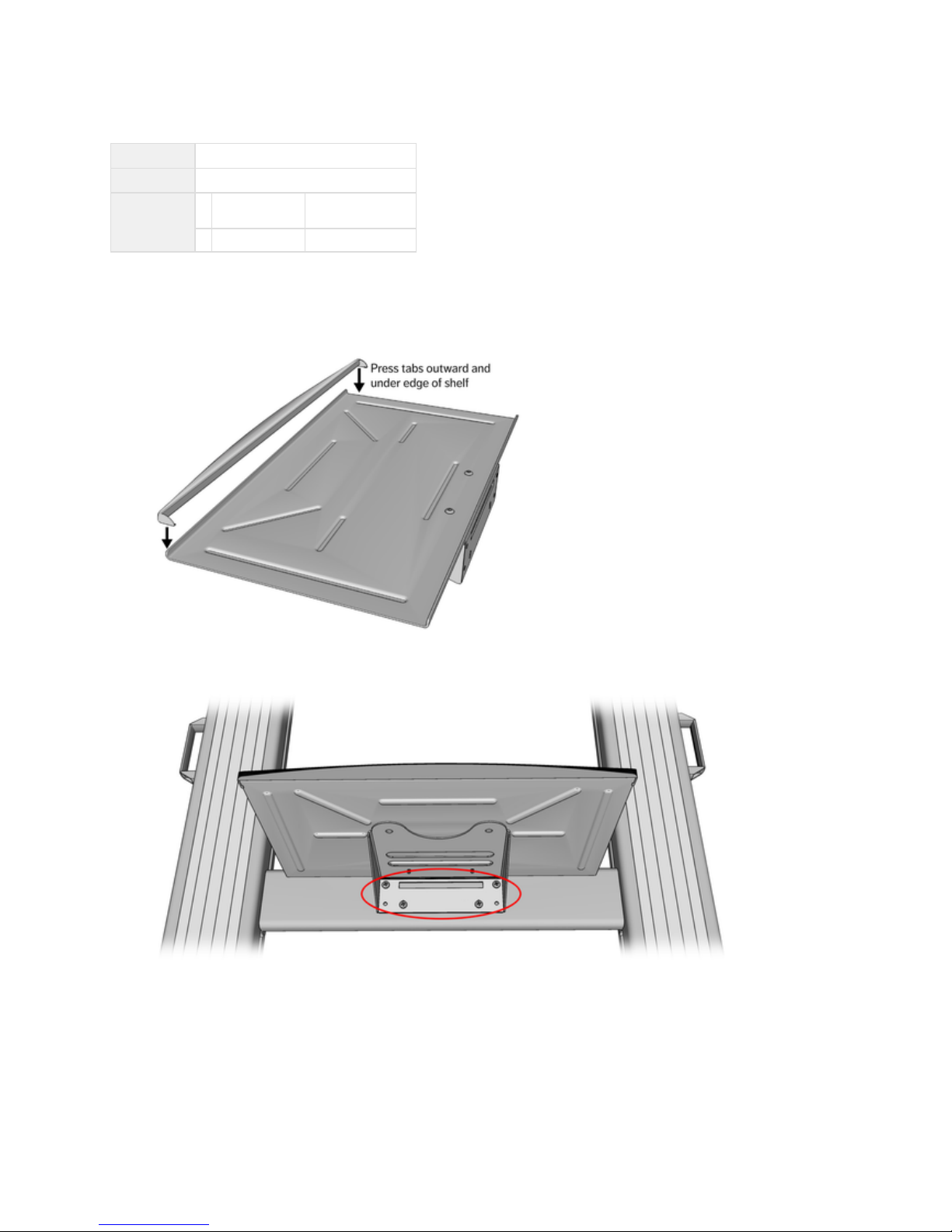
Connect the plastic Wrist Rest to the Keyboard Shelf by pressing it over the front lip of the shelf, then spread the tabs on either side
and snap them around the edge of the shelf. This takes a little effort to get it locked into place.
With a #2 Phillips screw driver, remove the four screws from the connector plate of the Keyboard Shelf.
At the front of the stand, hold the Keyboard Shelf up against the Center Support.
Fasten the shelf with the four screws through the holes in the underside of the shelf into the holes in the Center Support.
Page 42
Prysm LCD Visual Workplace Assembly Guide 520-00072-00 Rev 12
42Copyright © 2017, Prysm Inc. All rights reserved. Confidential and proprietary.
5. If you need to adjust the height of the keyboard shelf (recommended 10" down from the lowest edge of the display), loosen the two
screws of the Center Support, slide the assembly up or down, then re-tighten the screws.
Page 43
Prysm LCD Visual Workplace Assembly Guide 520-00072-00 Rev 12
43Copyright © 2017, Prysm Inc. All rights reserved. Confidential and proprietary.
1.
2.
3.8 Apply the Labels
Jump to > 2.1 Parts of the Prysm LCD Visual Workplace Stand
# of
Installers
One
Parts
Labels 110-4899-00
From the carton (050-00352-00).Open Me First
If for the Prysm 85 Dual, you will also need the labels from the cartonPrysm 85 Dual LCD and Cart Kit
(050-00355-00).
3.8.1 Instructions
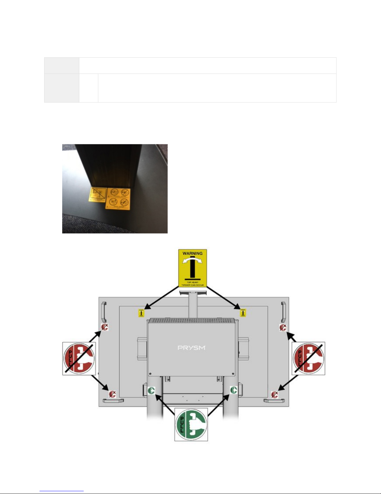
Peel off the yellow warning labels from the Base of the stand.
Apply the Prysm labels to the rear of the Prysm Visual Workplace stand as shown below:
Page 44
Prysm LCD Visual Workplace Assembly Guide 520-00072-00 Rev 12
44Copyright © 2017, Prysm Inc. All rights reserved. Confidential and proprietary.
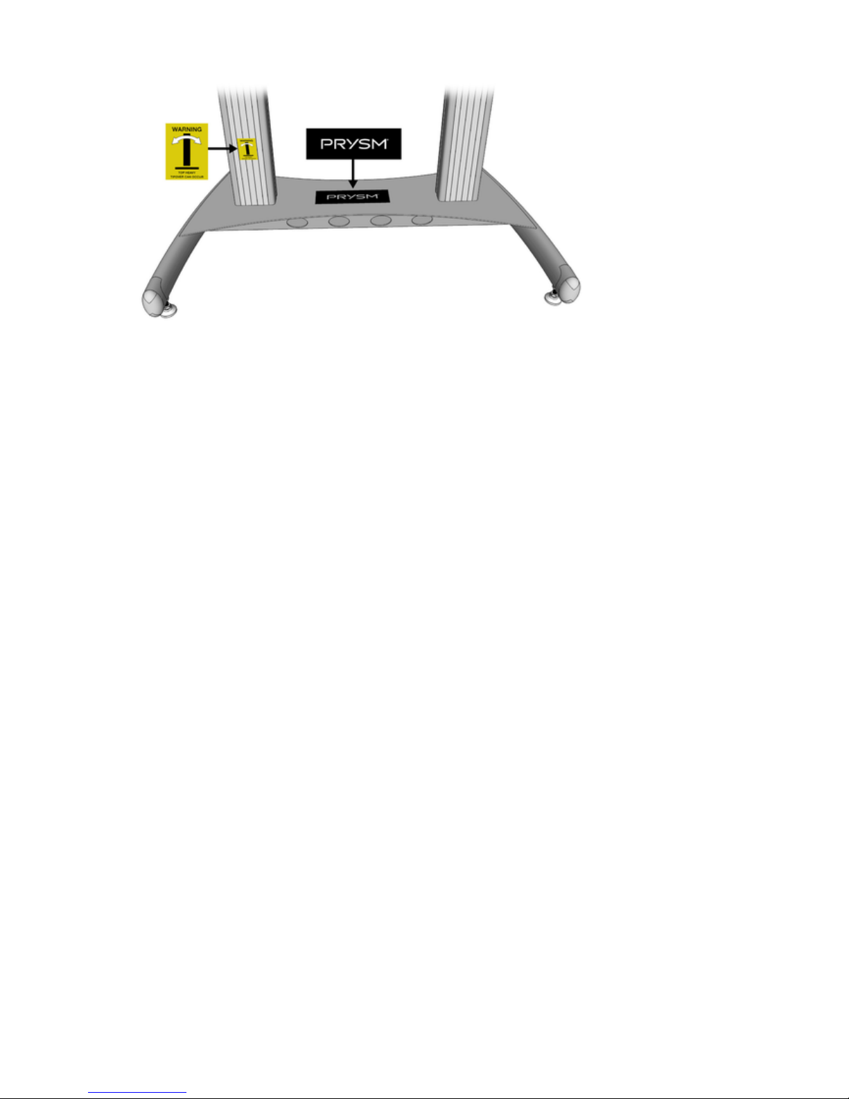
3. Apply the labels to the front of the left column and to the base of the as shown below:Prysm Visual Workplace stand
Page 45

Prysm LCD Visual Workplace Assembly Guide 520-00072-00 Rev 12
45Copyright © 2017, Prysm Inc. All rights reserved. Confidential and proprietary.
4. Cabling Procedures
The following sections have procedures to install cabling on the different Prysm LCD Visual Workplace products.
Select the section from the three listed below that corresponds to the product you are installing.
4.1 Cable the Prysm 98
4.2 Cable the Prysm 86, 85, 84, 75, 65, and 65 Core
4.3 Cable the Prysm 85 Dual
Page 46
Prysm LCD Visual Workplace Assembly Guide 520-00072-00 Rev 12
46Copyright © 2017, Prysm Inc. All rights reserved. Confidential and proprietary.
4.1 Cable the Prysm 98
Jump to > 2.1 Parts of the Prysm LCD Visual Workplace Stand
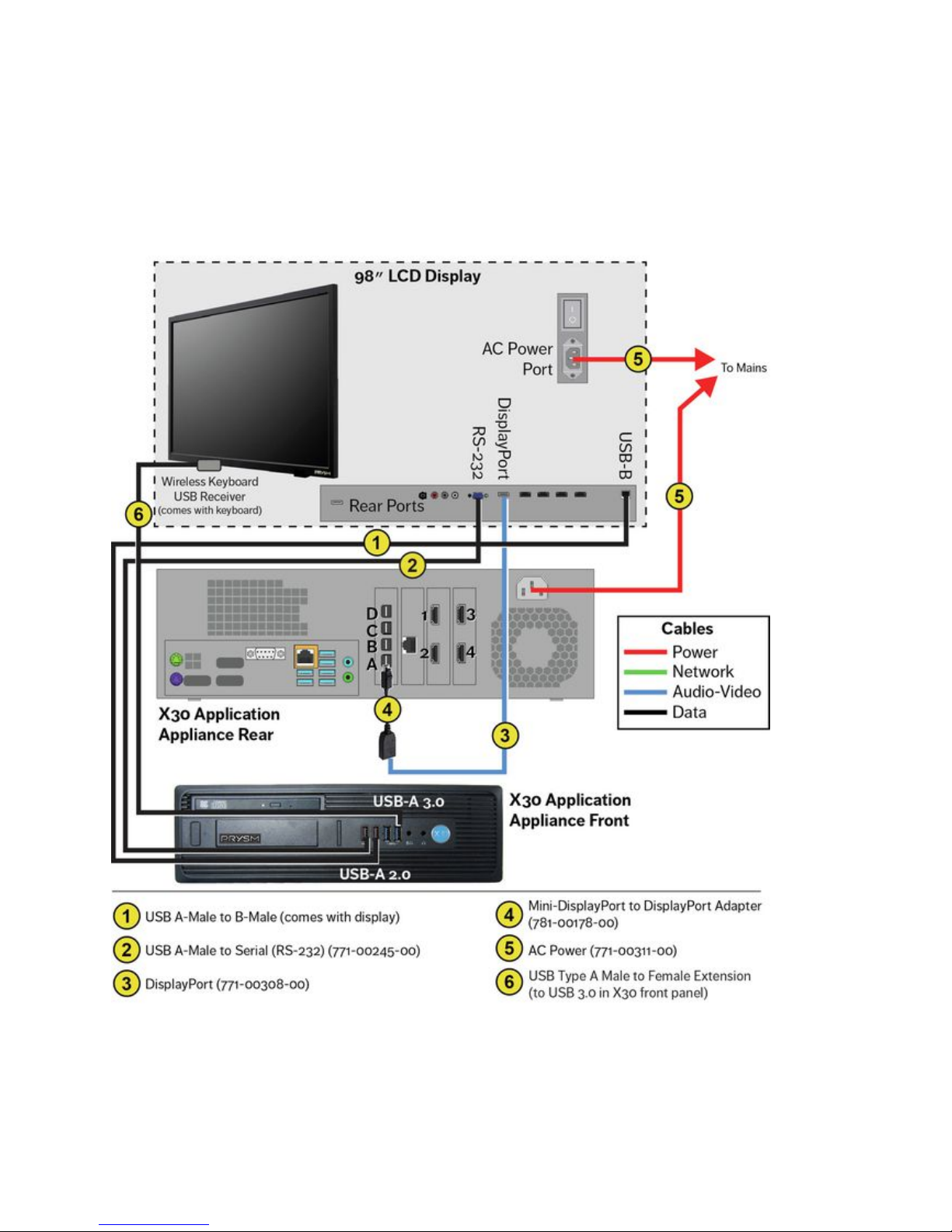
The following diagram shows the complete cabling for the Prysm LCD 98 Visual Workplace. Cables are color-coded by type and the numbers
on each cable are explained in the legend at the bottom of the diagram.
Prysm 98 Cabling Diagram
Page 47

Prysm LCD Visual Workplace Assembly Guide 520-00072-00 Rev 12
47Copyright © 2017, Prysm Inc. All rights reserved. Confidential and proprietary.
Parts List
# of Installers
Two
Parts
Display stand as currently assembled with System Cabinet.
Cables from the
Cable Kit
1 USB 2.0 A-Male to Serial (RS-232), 10 ft 771-00245-00
To be installed, but not connected to the rear of the X30 until needed.
1 DisplayPort, Male-to-Male, w/Latches, 6 ft 771-00308-00
Adapter from
X30 carton
4 Locking MDP to DP Adapters (only one
needed)
781-00178-00
1 Power, 6 ft N/A
Cables from
the
display carton
1 HDMI, 6 ft (not used) N/A
1 USB 2.0 A-Male to B-Male, 6 ft N/A
1 IR Extender ( )not used N/A - The Prysm 98 display has a receiver built into the lower front of the
display.
1 Power, 6 ft N/A
Hardware
1 Prysm Visual Workplace stand as currently assembled
Labels or pieces of paper tape to use as labels For labeling the free ends
of specific cables
Page 48
Prysm LCD Visual Workplace Assembly Guide 520-00072-00 Rev 12
48Copyright © 2017, Prysm Inc. All rights reserved. Confidential and proprietary.
1.
a.
b.
Cabling Instructions
Network Cables
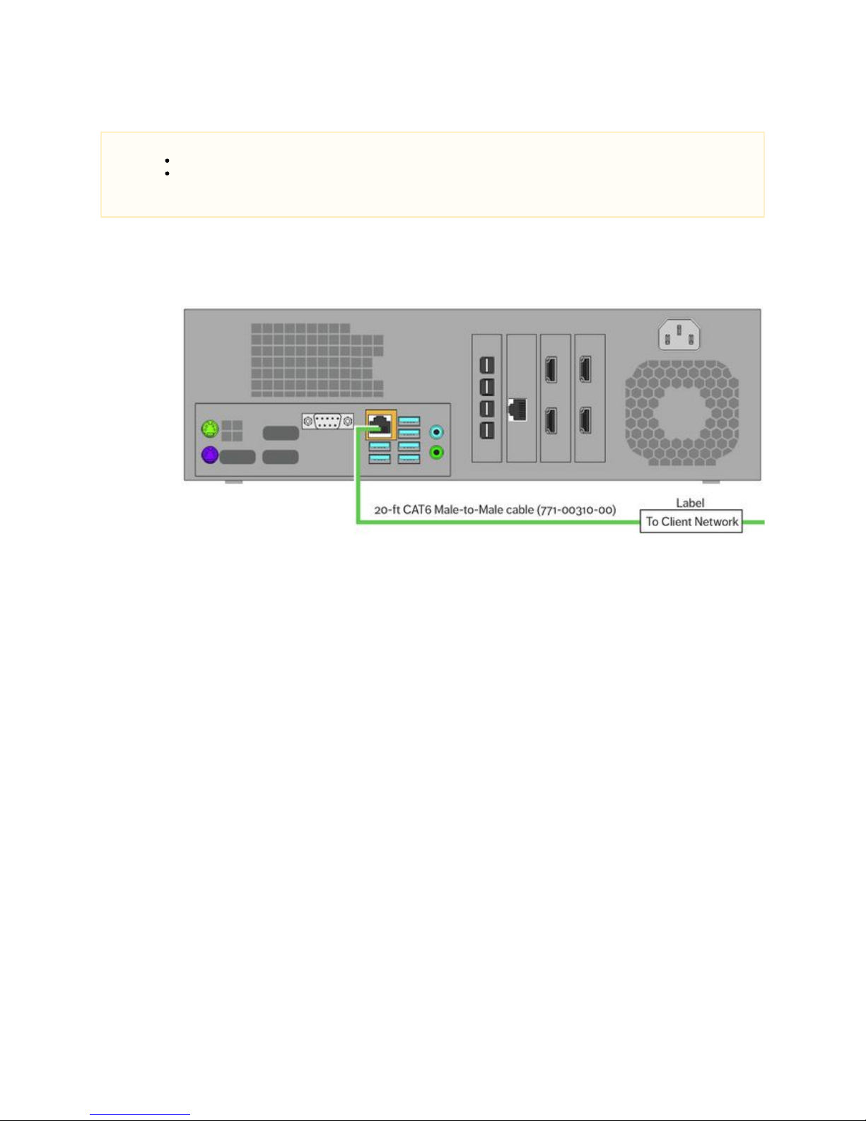
Connect the 20-foot CAT6 Male-to-Male cable (771-00310-00) as shown here:
Connect one end to the LAN port of the main board of the X30.
Mark the free end of this cable with a label to indicate that it will be connected to the client network.
NOTES
It is a good practice to label the free ends of the cables that will be routed to a specific source.
An Interactive Input Controller does not come standard with the Prysm 98. he IIC can be purchased separatelyHowever, t
and added to the system. If you are installing a system that has an IIC, following the IIC-specific instructions in 4.2 Cable
.the Prysm 86, 85, 84, 75, 65, and 65 Core
Page 49
Prysm LCD Visual Workplace Assembly Guide 520-00072-00 Rev 12
49Copyright © 2017, Prysm Inc. All rights reserved. Confidential and proprietary.
1.
a.
b.
c.
Control Cables
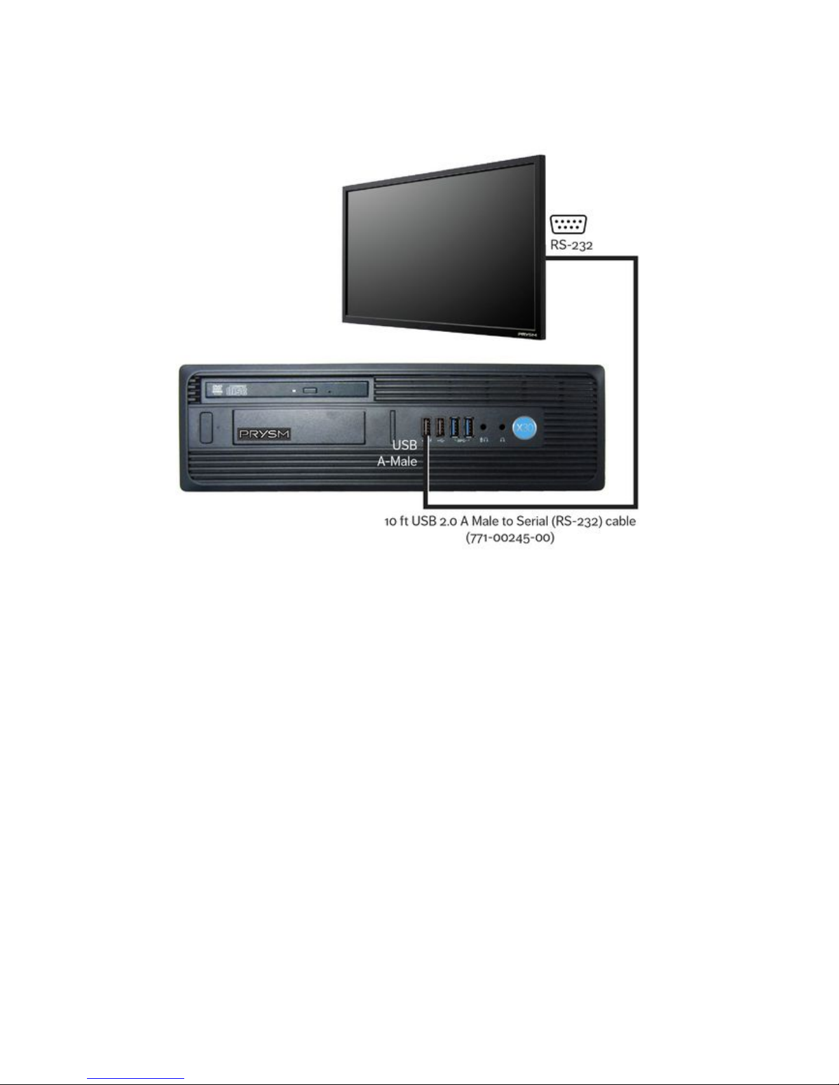
Connect the 10-foot USB 2.0 A Male to Serial (RS-232) cable ( as shown here:771-00245-00)
Connect the USB connector to any USB port on the rear panel of the X30.
Route the Serial end through the cabinet's grommet hole.
Connect the Serial (RS-232) connector to the RS-232 port on the display.
Page 50
Prysm LCD Visual Workplace Assembly Guide 520-00072-00 Rev 12
50Copyright © 2017, Prysm Inc. All rights reserved. Confidential and proprietary.
2.
a.
b.
c.
1.
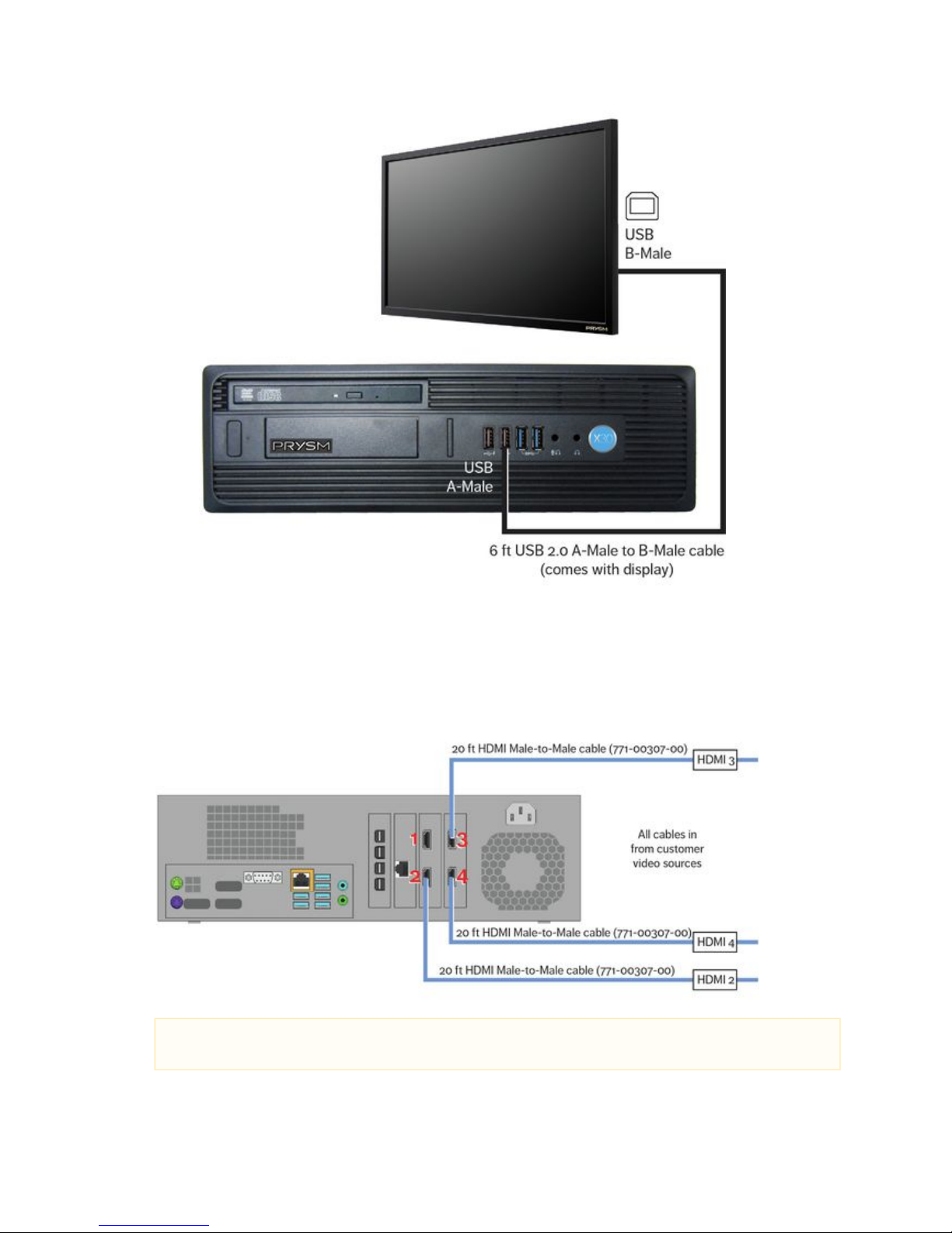
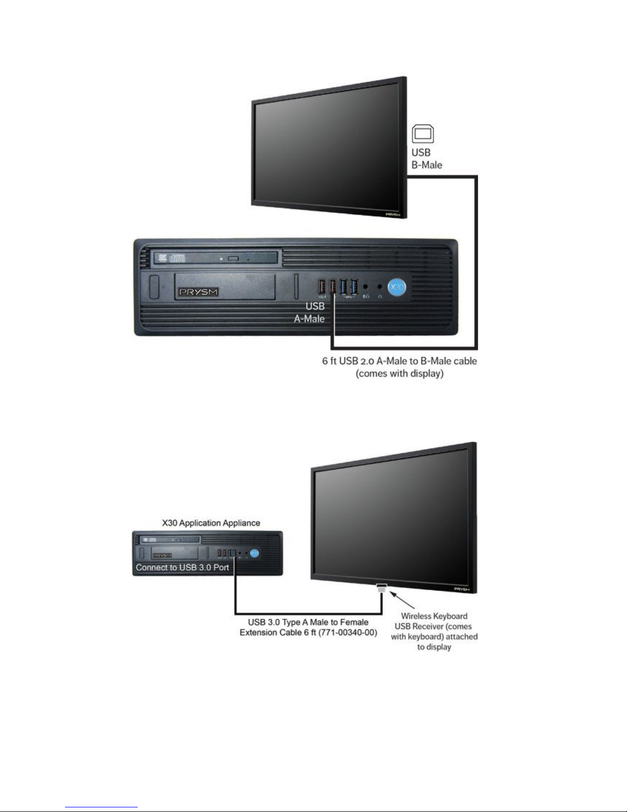
Connect the 6-foot USB 2.0 A-Male to B-Male cable ( ) as shown here:comes with display
Connect the USB A-Male connector to USB port on the rear panel of the X30.any
Route the USB-B end through the cabinet's grommet hole.
Connect the USB B-Male connector to the USB B-type port on the display.
Audio-Video Cables
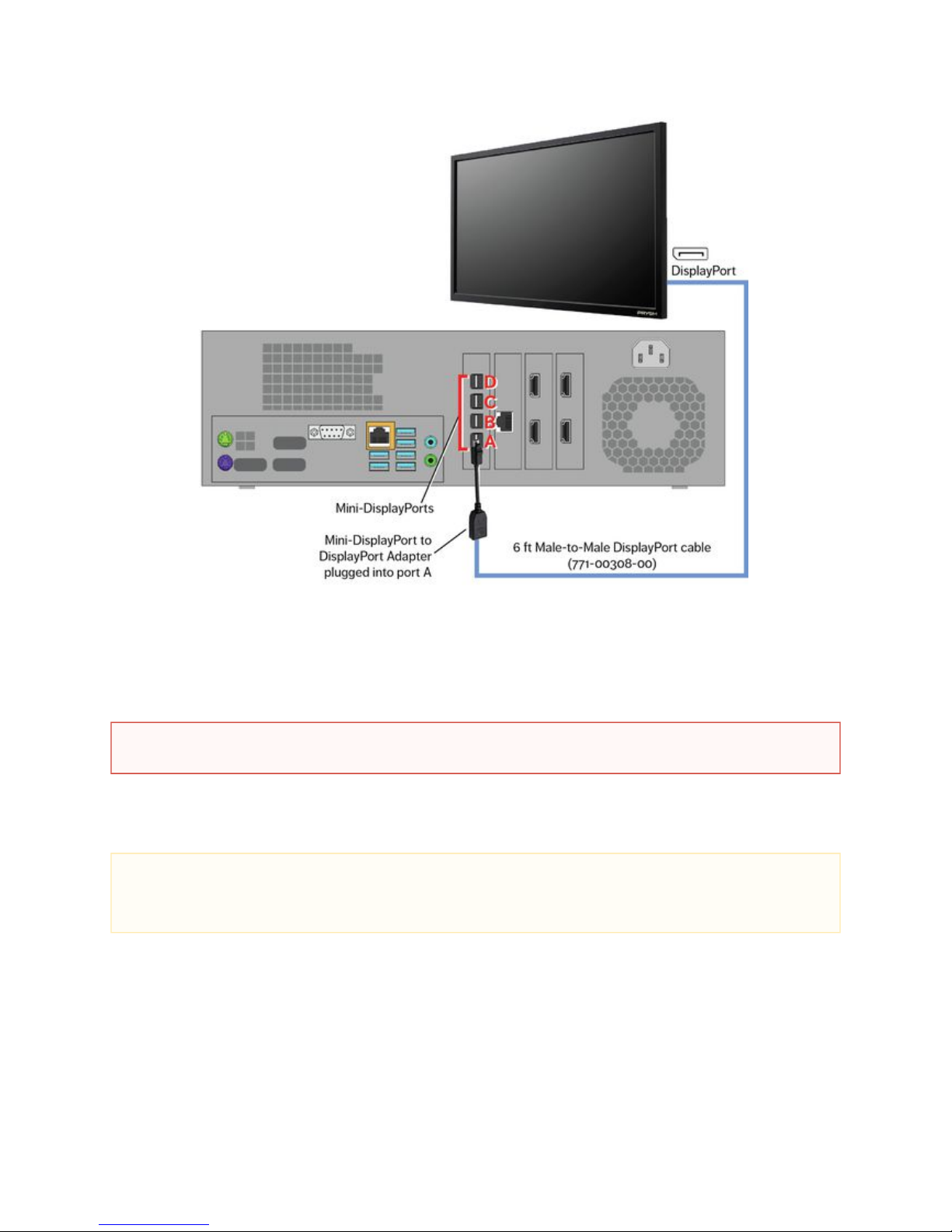
Connect the unlabeled end of each cable to the appropriate HDMI port on the rear of the X30 as shown here:
NOTE
The labeled ends of these HDMI cables will eventually go out to the live video sources.
Page 51
Prysm LCD Visual Workplace Assembly Guide 520-00072-00 Rev 12
51Copyright © 2017, Prysm Inc. All rights reserved. Confidential and proprietary.
2.
a.
b.
c.
d.
1.
2.
Connect the 6-foot Male-to-Male DisplayPort cable (771-00308-00) as shown in the illustration below:
Connect one end of the DisplayPort cable to a DisplayPort connection on the display.
Route the other end into the cabinet through the cable access hole.
Connect the large end of a L (781-00178-00, comes with X30)ocking Mini-DisplayPort to DisplayPort Adapter into the free
end of the DisplayPort cable.
Connect the small end of the adapter to the Mini-DisplayPort, Port A, in the rear of the X30.
Power Cables
Connect the C13 connector of the 6 ft cable directly to the Power In port near the On/Off switch of the that came with the display
display.
Connect the C13 connector of the 6 ft cable to the Power In port on the rear of thethat came with the X30 Application Appliance
Application Appliance.
WARNING
Make sure no electronic components or power cables of the Prysm Visual Workplace stand are connected to mains power.
NOTE
The Prysm LCD Visual Workplace systems accept voltages between 100v and 240v. However, the power cables that comes with
this product have 5-15P type plugs used for 110v receptacles. If the customer site does not have this voltage or these types of
receptacles, the customer must supply adapters for the supplied cables, or replacement cables.
Page 52

Prysm LCD Visual Workplace Assembly Guide 520-00072-00 Rev 12
52Copyright © 2017, Prysm Inc. All rights reserved. Confidential and proprietary.
Cable Routing
Connect each cable at it's appropriate destination, including the power cables.
Disable USB to Serial
Once all cables are routed, disconnect the USB end of the USB to RS-232 cable from the rear of the X30. It is not to be(771-00245-00)
connected until it is necessary to update the firmware of the display.
The cabling is complete. Proceed to .5. Startup Configuration
Page 53

Prysm LCD Visual Workplace Assembly Guide 520-00072-00 Rev 12
53Copyright © 2017, Prysm Inc. All rights reserved. Confidential and proprietary.
4.2 Cable the Prysm 86, 85, 84, 75, 65, and 65 Core
Jump to > 2.1 Parts of the Prysm LCD Visual Workplace Stand
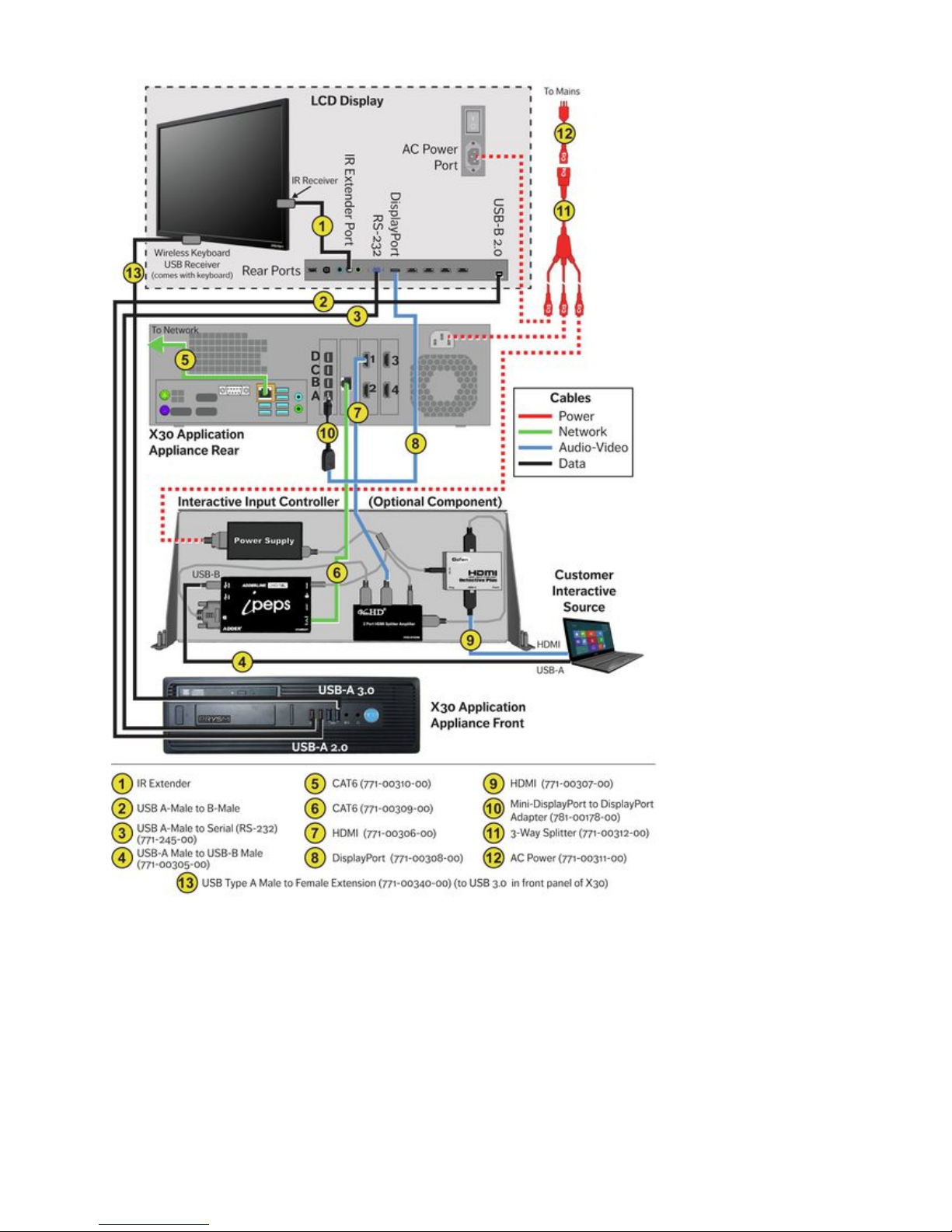
The following diagram shows the complete cabling for the Visual Workplace. Prysm LED 86, 85, 65, and 65 Core Cables are color-coded by
type and the numbers on each cable are explained in the legend at the bottom of the diagram.
Prysm 86, 85, 84, 75, 65, and 65 Core Cabling Diagram
The Prysm 86, Prysm 85, Prysm 65, and Prysm 65 Core connect to a Prysm X30 Application Appliance and (if included in the customer
order) an Interactive Input Controller.
Note
For specific ports and where they are located on the rear panel of a specific display, see the connection layouts in the Product
section.Component Diagrams
Page 54
Prysm LCD Visual Workplace Assembly Guide 520-00072-00 Rev 12
54Copyright © 2017, Prysm Inc. All rights reserved. Confidential and proprietary.
Page 55
Prysm LCD Visual Workplace Assembly Guide 520-00072-00 Rev 12
55Copyright © 2017, Prysm Inc. All rights reserved. Confidential and proprietary.
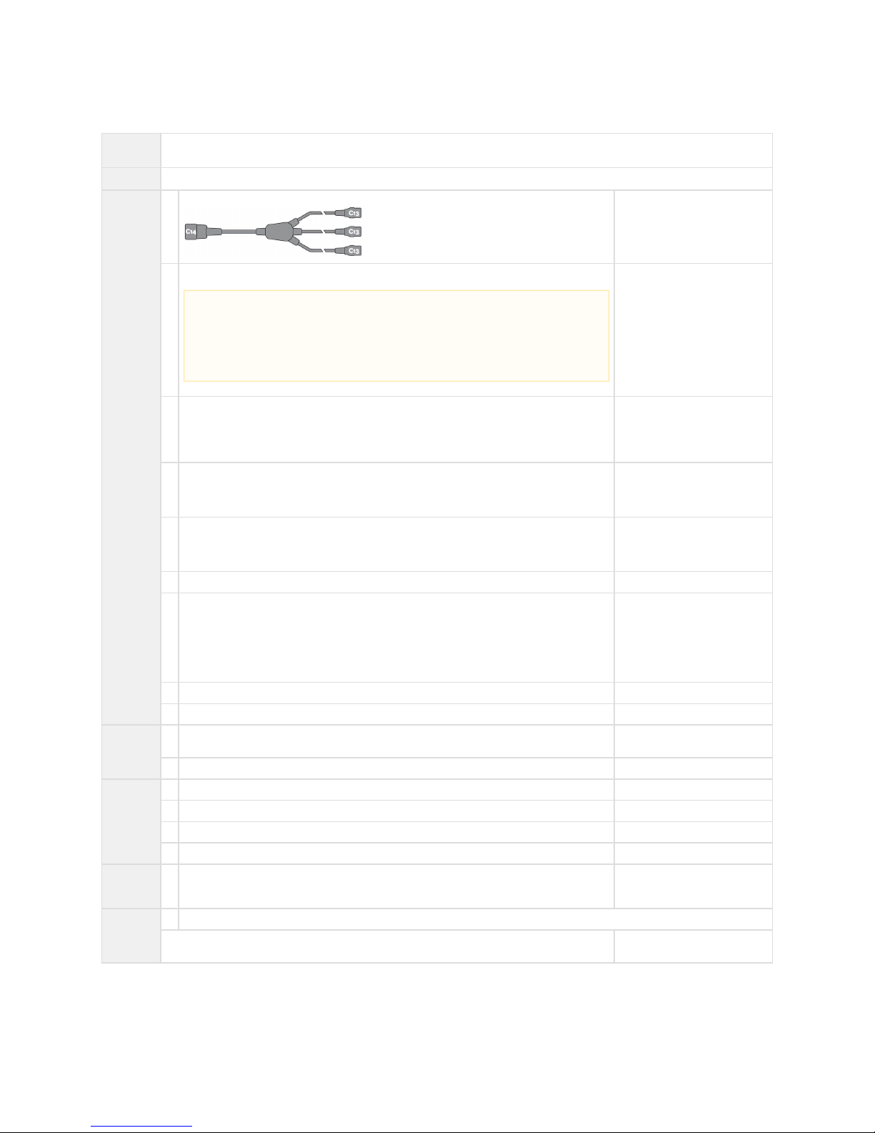
Parts List
# of
Installers
Two
Parts
Display stand as currently assembled with System Cabinet.
From the
Cable Kit
1 AC 3-Way Splitter, 1 C14 end to 3 C13 ends 771-00312-00
1 AC Power Cable, NEMA 5-15P to IEC C13, UNIV, 125V, 13A, 20 ft 771-00311-00
1 USB 2.0 A-Male to Serial (RS-232) Cable, 10 ft 771-00245-00
To be installed, but not connected
to the rear of the X30 until
needed.
1 USB 2.0 A-Male to B-Male Cable, w/ Ferrite, 20 ft 771-00305-00
Replaces the 12 ft USB cable in
the optional IIC
4 HDMI, Male-to-Male Cable, CL2-Rated, 20 ft 771-00307-00
One of these replaces the 12 ft
HDMI cable in the optional IIC
1 HDMI, Male-to-Male, 2 ft 771-00306-00
1 DisplayPort, Male-to-Male, w/Latches, 6 ft 771-00308-00
If you are assembling a Prysm 85
Dual, replace this cable with the
25 ft DisplayPort cable in the
Prysm 85 Dual carton
(771-00322-00).
1 CAT6, Male-to-Male, RJ45, 2 ft 771-00309-00
1 CAT6, Male-to-Male, RJ45, 20 ft 771-00310-00
From
X30
carton
4 Locking MDP to DP Adapters (only need one for this setup) 781-00178-00
Comes with X30
1 Power Cable, 6 ft (not used) N/A
From the
display
carton
1 HDMI Cable, 6 ft (not used) N/A
1 USB 2.0 A-Male to B-Male Cable, 6 ft N/A
1 IR Extender Cable N/A
1 Power Cable, 6 ft ( )not used N/A
From the
Misc.
Parts Kit
1 USB 3.0 Type A Male to Female Extension Cable, 6 ft. 771-00340-00
Hardware
1 Prysm Visual Workplace stand as currently assembled
Labels or pieces of paper tape to use as labels For labeling the free ends
of specific cables
Note
The Prysm LCD Visual Workplace systems accept voltages between 100v and 240v.
However, the 20 ft power cable that comes with this product (771-00311-00) has a
5-15P type plug used for 110v receptacles. If the customer site does not have this type
of power or receptacle, the customer must supply an adapter for the supplied cable, or a
replacement cable.
Page 56
Prysm LCD Visual Workplace Assembly Guide 520-00072-00 Rev 12
56Copyright © 2017, Prysm Inc. All rights reserved. Confidential and proprietary.
1.
a.
b.
Cabling Instructions
Network Cables
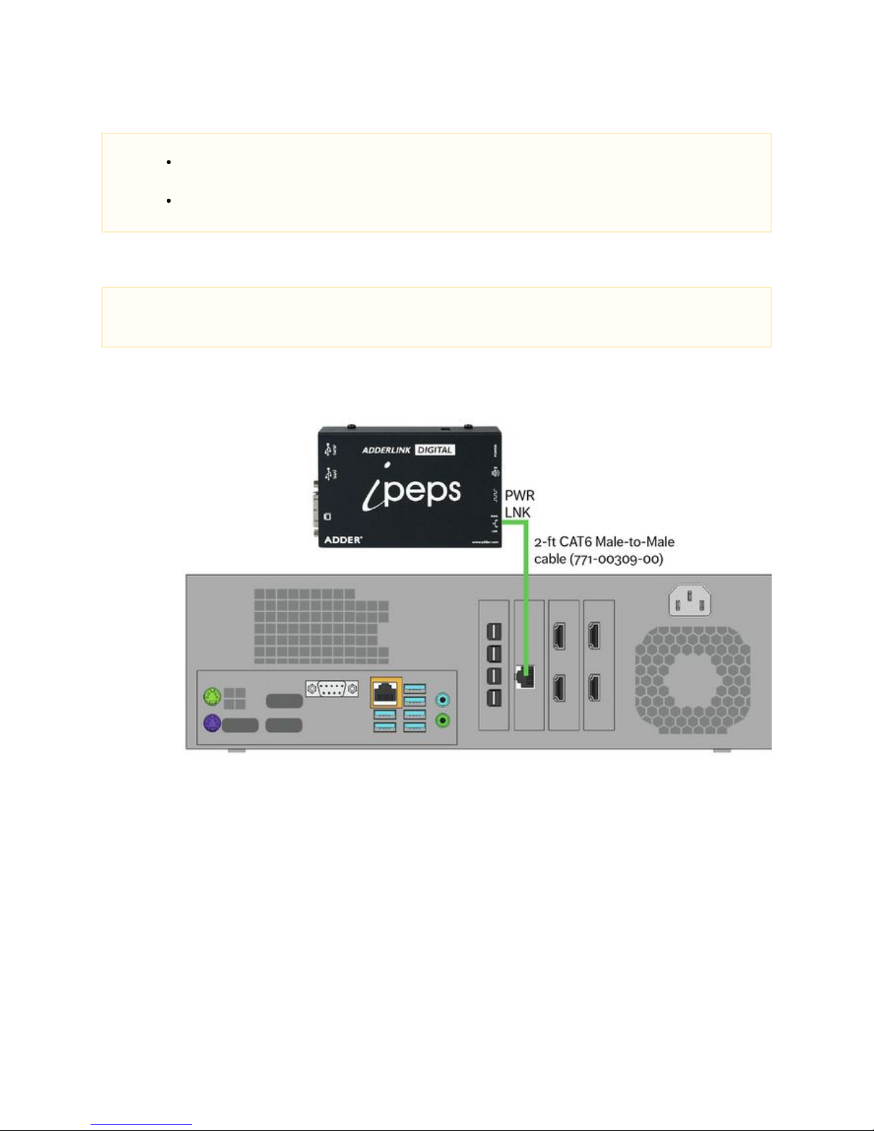
Connect the 2-foot CAT6 Male-to-Male cable (771-00309-00) as shown here:
Connect one end to the LAN port on the Network Card on the Prysm X30 Application Appliance between the two HDMI
cards.
Connect the other end to the PWR-LNK port on the Adderlink ipeps unit of the IIC.
Notes
There will be cables exiting the System Cabinet that will be routed down one of the stand's Support Columns. There will be
other cables that will exit the cabinet to connect directly to the display. Ensure that the cables that go to the display are not
bundled with the other cables.
It is a good practice to label the free ends of the cables that will be routed down a Support Column and out to a specific
source.
Note
The following connection is for the optional Interactive Input Controller. If customer order does not include an IIC,
proceed to step 2.
Page 57
Prysm LCD Visual Workplace Assembly Guide 520-00072-00 Rev 12
57Copyright © 2017, Prysm Inc. All rights reserved. Confidential and proprietary.
2.
a.
b.
1.
a.
b.
c.
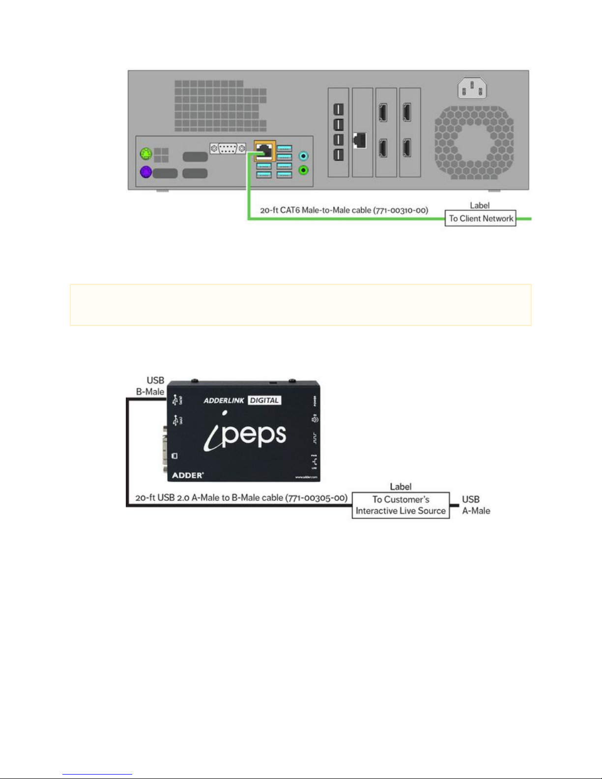
Connect the 20-foot CAT6 Male-to-Male cable (771-00310-00) as shown here:
Connect one end to the LAN port of the main board of the X30.
Mark the free end of this cable with a label to indicate that it will be connected to the client network.
Control Cables
Connect the as shown in the illustration below:20-foot USB 2.0 A-Male to B-Male cable (771-00305-00)
Remove the 12-foot USB 2.0 A-Male to B-Male cable from the IIC by disconnecting it from the K/M port on the ipeps unit.
In place of the removed cable, connect the 20-foot USB 2.0 A-Male to B-Male cable (771-00305-00).
Mark the free end of this cable with a label indicating that it will be connected to the customer's Interactive Live Source (such
as a laptop).
Note
The following connection is for the optional Interactive Input Controller. If customer order , does not include an IIC
proceed to step 3.
Page 58
Prysm LCD Visual Workplace Assembly Guide 520-00072-00 Rev 12
58Copyright © 2017, Prysm Inc. All rights reserved. Confidential and proprietary.
2.
a.
b.
c.
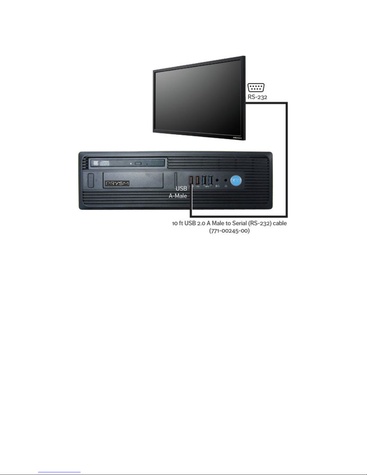
Connect the 10-foot USB 2.0 A Male to Serial (RS-232) cable ( as shown here:771-00245-00)
Connect the USB connector to any USB port on the rear panel of the X30.
Route the Serial end through the cabinet's grommet hole.
Connect the Serial (RS-232) connector to the RS-232 port on the display.
Page 59
Prysm LCD Visual Workplace Assembly Guide 520-00072-00 Rev 12
59Copyright © 2017, Prysm Inc. All rights reserved. Confidential and proprietary.
3.
a.
b.
c.
d.
e.
Connect the USB 3.0 Type A Male to Female Extension (771-00340-00) as shown here:
Connect the USB 3.0 Type A Male to Female Extension to the USB port on the front of the X30 Application Appliance.
Route the cable from the Application Appliance through the cabinet and down towards the bottom of the display.
Connect the wireless keyboard receiver to the end of the USB Extension.
Apply a section of the Velcro Tape (773-00151-00) to the bottom of the display and the USB Extension cable end with the
receiver.
Attach the USB Extension cable with the receiver to the bottom of the display.
Page 60
Prysm LCD Visual Workplace Assembly Guide 520-00072-00 Rev 12
60Copyright © 2017, Prysm Inc. All rights reserved. Confidential and proprietary.
4.
a.
b.
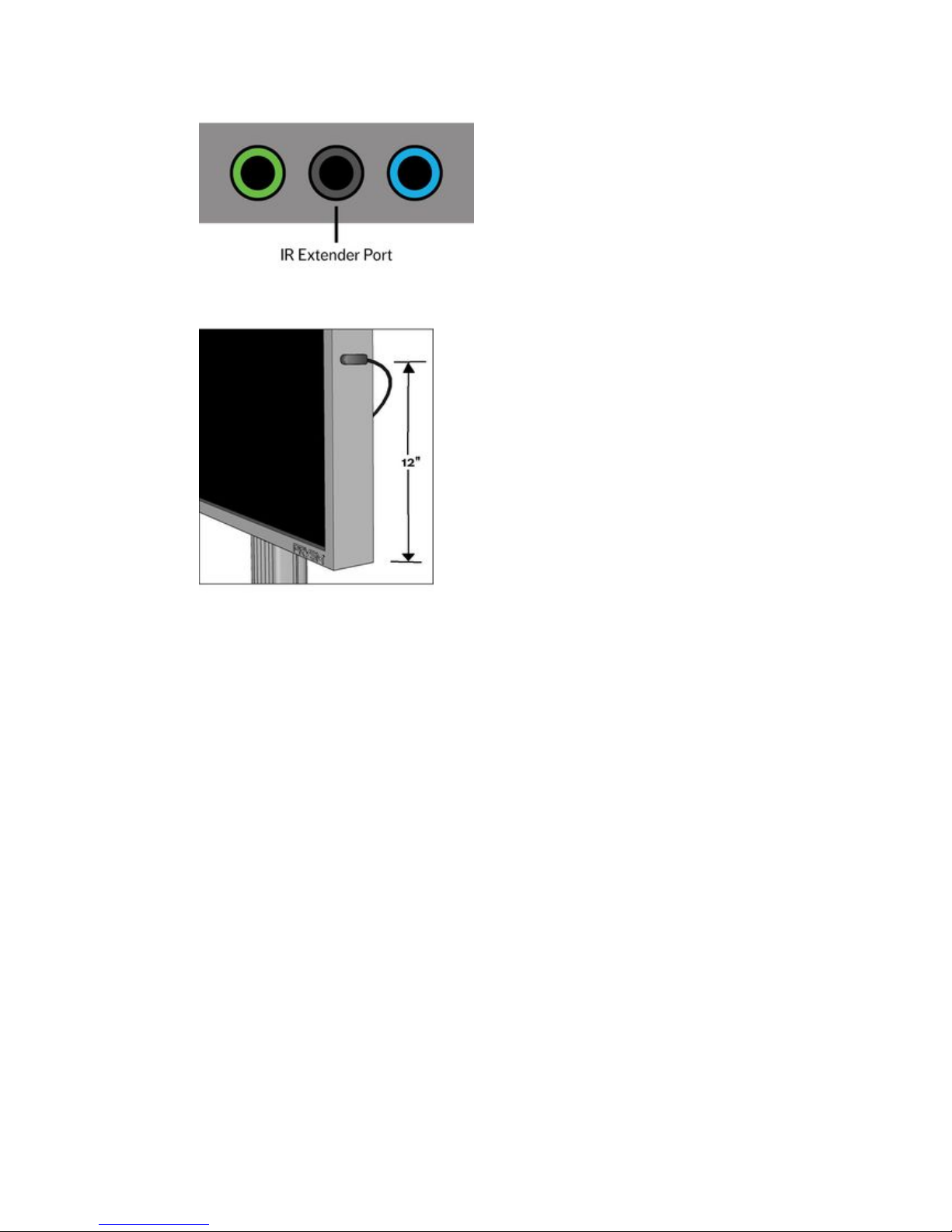
Connect the IR Extender Cable (comes with display) as shown here:
Connect the IR Extender Cable jack to the round black port on the display.
The IR Receiver must be attached to the right side edge of the display as viewed facing the display. Peel the tape off the
double stick material on the IR Receiver and stick the receiver 12" up from the base, making sure the rounded end of the
receiver is facing outward (toward the viewer).
Page 61
Prysm LCD Visual Workplace Assembly Guide 520-00072-00 Rev 12
61Copyright © 2017, Prysm Inc. All rights reserved. Confidential and proprietary.
1.
a.
b.
2.
a.
b.
c.
Audio-Video Cables
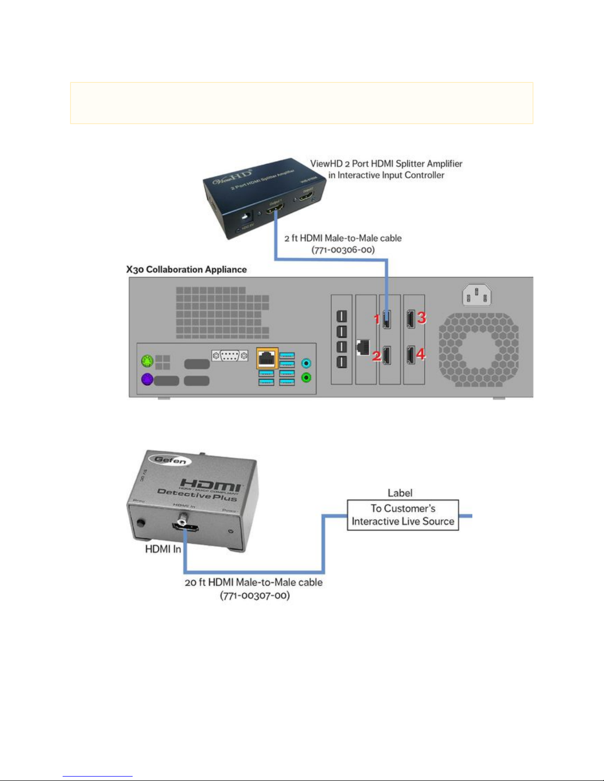
Connect the 2-foot HDMI Male-to-Male cable (771-00306-00) as shown here:
Connect one end to the HDMI In port (HDMI 1) on the X30:
Connect the other end to the Output 1 port on the ViewHD HDMI Splitter Amplifier on the IIC shelf.
Replace the 12-foot HDMI Male-to-Male cable on the IIC as shown here:
Disconnect the cable from the HDMI In port of the HDMI Detective Plus unit.
In its place, connect the 20-foot HDMI Male-to-Male cable (771-00307-00).
Mark the free end of this cable with a label to indicate that it will connect to the customer's Interactive Live Source (such as a
laptop).
Note
The following two connections are for the optional Interactive Input Controller. If customer order , does not include an IIC
proceed to step 3.
Page 62
Prysm LCD Visual Workplace Assembly Guide 520-00072-00 Rev 12
62Copyright © 2017, Prysm Inc. All rights reserved. Confidential and proprietary.
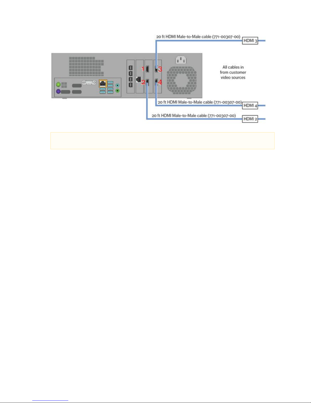
3. Connect the unlabeled end of each cable to the appropriate HDMI port on the rear of the X30 as shown here:
Note
The labeled ends of these HDMI cables will eventually go out to the live video sources.
Page 63
Prysm LCD Visual Workplace Assembly Guide 520-00072-00 Rev 12
63Copyright © 2017, Prysm Inc. All rights reserved. Confidential and proprietary.
4.
a.
b.
c.
d.
1.
2.
3.
4.
5.
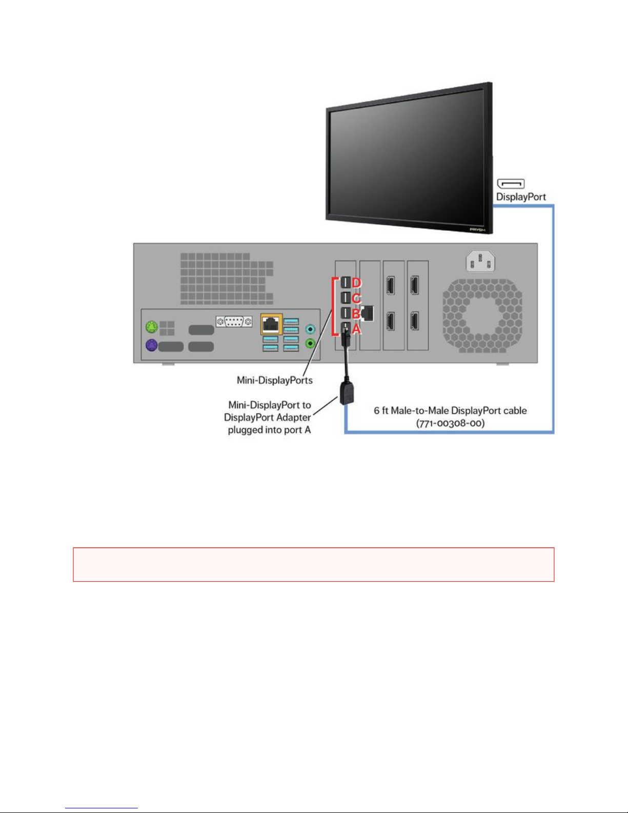
Connect the 6-foot Male-to-Male DisplayPort cable (771-00308-00) as shown in the illustration below:
Connect one end of the DisplayPort cable to a DisplayPort connection on the display.
Route the other end into the cabinet through the cable access hole.
Connect the large end of a L (781-00178-00, comes with X30)ocking Mini-DisplayPort to DisplayPort Adapter into the free
end of the DisplayPort cable.
Connect the small end of the adapter to the Mini-DisplayPort, Port A, in the rear of the X30.
Power Cables
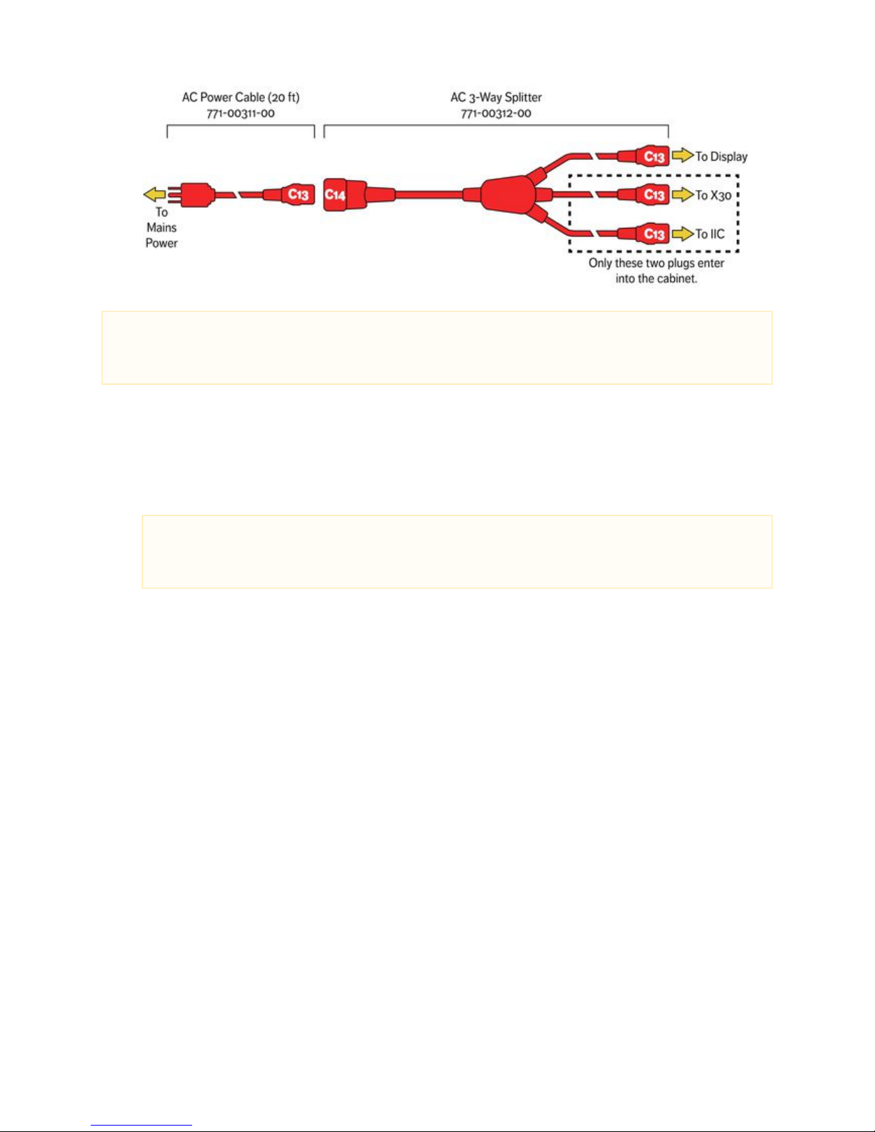
Holding the end of the C13 connectors, feed an connector and theAC 3-Way Splitter Cable (771-00312-00) with the three outer
center connector though the cable access hole the cabinet. Leave the third C13 connector end and the C4 end of theinto outer
cable of the cabinet.outside
Connect the C13 connector cable outside of the cabinet directly to the Power In port near the On/Off switch of the display.
Inside the cabinet, connect the center C13 connector cable from the AC 3-Way Splitter Cable to the Power In port of the X30.
If IIC included: Remove the power cable connected to the Power Supply in the Interactive Input Controller. This will not be needed.
If IIC included: Connect the other C13 connector cable from the AC 3-Way Splitter Cable to the Power Supply on the Interactive
Input Controller.
WARNING
Make sure no electronic components or power cables of the Prysm Visual Workplace stand are connected to Mains power.
Page 64
Prysm LCD Visual Workplace Assembly Guide 520-00072-00 Rev 12
64Copyright © 2017, Prysm Inc. All rights reserved. Confidential and proprietary.
6.
1.
2.
3.
Connect the C14 end of the AC 3-Way Splitter Cable to the 20 ft AC extension cable (771-00311-00).
Cable Routing
Gather all cables that are to be routed out to sources.
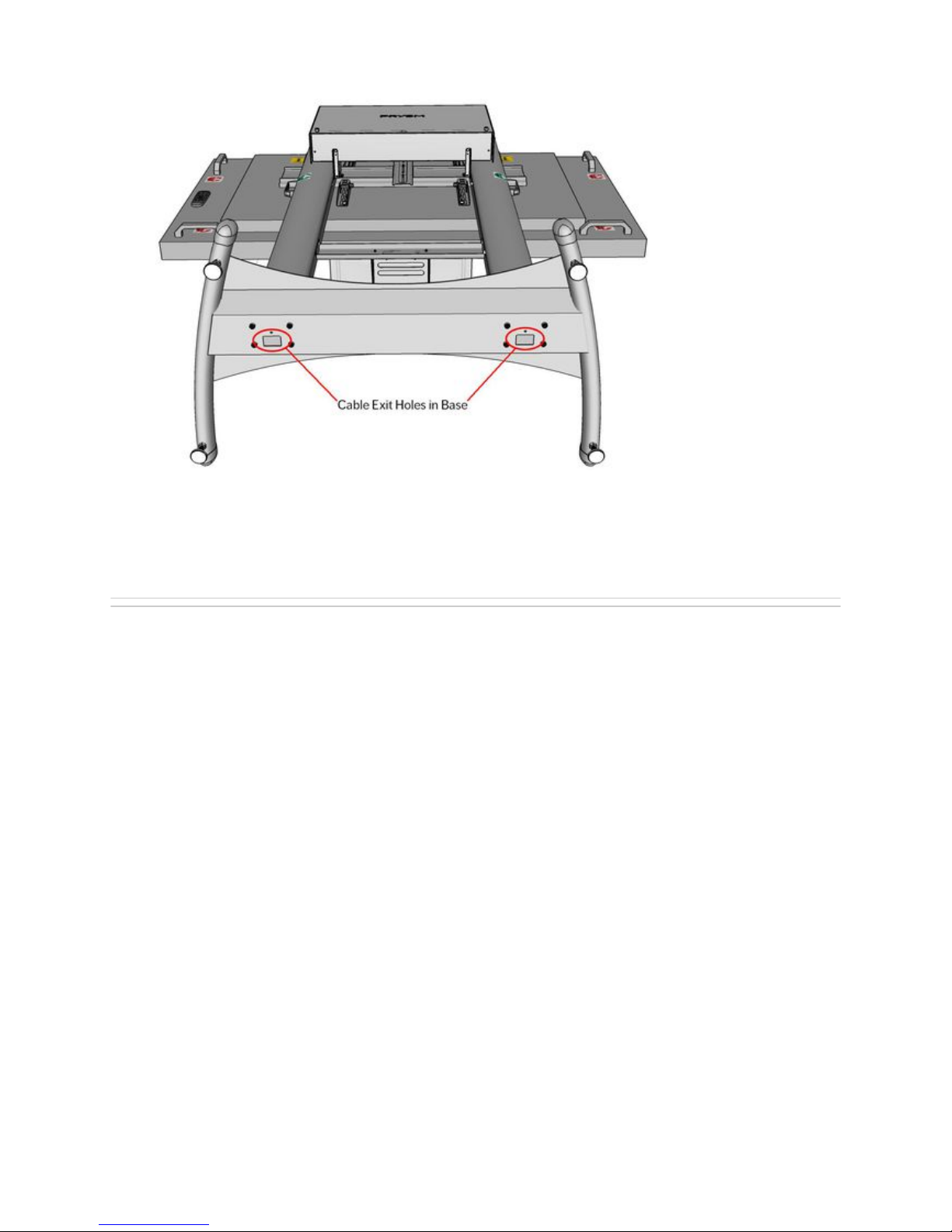
Feed the cables installed previously in the cabinet out through the cable access hole in the back of the cabinet shelf.
To feed the cables down one of the columns, gather the ends so that none of the connectors is next to each other. If the connectors
are bunched up they won't go through the column's grommet hole.
Note
The Prysm Visual Workplace systems accept voltages between 100v and 240v. However, the 20 ft power cable that comes with
this product (771-00311-00) has a 5-15P type plug used for 110v receptacles. If the customer site does not have this type of power
or receptacle, the customer must supply an adapter for the supplied cable, or a replacement cable.
Note
The plastic grommets in the Support Columns have a tendency to push through and get lost in the columns. It is best to
remove the grommet on the hole into which you will be feeding the cables. Also, take care not to damage cables by
dragging them against the rough edge of the grommet holes.
Page 65
Prysm LCD Visual Workplace Assembly Guide 520-00072-00 Rev 12
65Copyright © 2017, Prysm Inc. All rights reserved. Confidential and proprietary.
4.
5.
Using two people, have one person feed the cables down the hole while the other person pulls the cables down from the column
hole . Carefully pull them all the way through.on the underside of the stand base
Once all cables are through, connect each cable at it's appropriate destination, including the power cable.
Disable USB to Serial
Once all cables are routed, disconnect the USB end of the USB to RS-232 cable from the rear of the X30. It is not to be(771-00245-00)
connected until it is necessary to update the firmware of the display.
The cabling is complete. Proceed to 5. Startup Configuration.
Page 66

Prysm LCD Visual Workplace Assembly Guide 520-00072-00 Rev 12
66Copyright © 2017, Prysm Inc. All rights reserved. Confidential and proprietary.
4.3 Cable the Prysm 85 Dual
Jump to > 2.1 Parts of the Prysm LCD Visual Workplace Stand
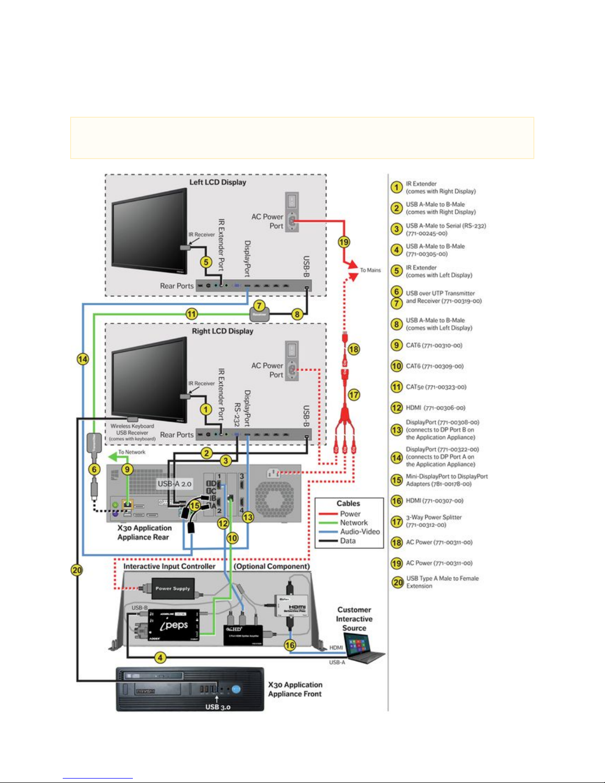
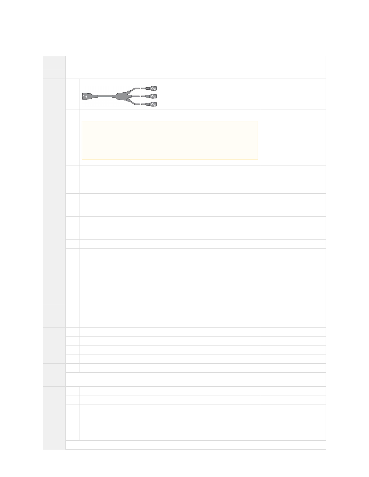
The following diagram shows the complete cabling for the Prysm LED 85 Dual Visual Workplace.
Cables are color-coded by type, as shown in the first diagram. The numbers on each cable or part refer to descriptions in the table below the
diagram.
NOTE
The two displays are called the Left and Right displays, determined by standing facing the front screens of the displays.
Page 67
Prysm LCD Visual Workplace Assembly Guide 520-00072-00 Rev 12
67Copyright © 2017, Prysm Inc. All rights reserved. Confidential and proprietary.
Prysm 85 Dual Cabling Diagram
The Prysm 85 Dual has two displays that share a Prysm X30 Application Appliance and (if included in the customer order) an Interactive
Input Controller.
NOTE
Make sure you connect the DisplayPort cables as follows: Connect DisplayPort A to the DisplayPort on the Left display and
DisplayPort B to the DisplayPort on the Right display. This is shown in the 13 and 14.following diagram as cables
Page 68
Prysm LCD Visual Workplace Assembly Guide 520-00072-00 Rev 12
68Copyright © 2017, Prysm Inc. All rights reserved. Confidential and proprietary.
Parts List
# of
Installers
Two
Parts
Display stand as currently assembled with System Cabinet.
Cables
from the
Cable Kit
1 AC 3-Way Splitter, 1 C14 end to 3 C13 ends 771-00312-00
1 AC Power, NEMA 5-15P to IEC C13, UNIV, 125V, 13A, 20 ft 771-00311-00
1 USB 2.0 A-Male to Serial (RS-232), 10 ft 771-00245-00
To be installed, but not connected
to the rear of the X30 until
needed.
1 USB 2.0 A-Male to B-Male, w/ Ferrite, 20 ft 771-00305-00
Replaces the 12 ft USB cable in
the optional IIC.
4 HDMI, Male-to-Male, CL2-Rated, 20 ft 771-00307-00
One of these replaces the 12 ft
HDMI cable in the optional IIC.
1 HDMI, Male-to-Male, 2 ft 771-00306-00
1 DisplayPort, Male-to-Male, w/Latches, 6 ft 771-00308-00
If you are assembling a Prysm 85
Dual, replace this cable with the
25 ft DisplayPort cable in the
Prysm 85 Dual carton
(771-00322-00).
1 CAT6, Male-to-Male, RJ45, 2 ft 771-00309-00
1 CAT6, Male-to-Male, RJ45, 20 ft 771-00310-00
Adapter
from
X30
Carton
4 Locking MDP to DP Adapters (only need one for this setup) 781-00178-00
From X30 carton
Cables
from the
Display
Carton
1 HDMI, 6 ft (not used) N/A
1 USB 2.0 A-Male to B-Male, 6 ft N/A
1 IR Extender N/A
1 Power, 6 ft N/A
Hardware
1 Prysm Visual Workplace stand as currently assembled
Labels or pieces of paper tape to use as labels For labeling the free ends of
specific cables
Parts
and
Cables
from
Prysm 85
Dual LCD
and
Cart Kit
carton
4 Leveling Feet (if requested) 773-01358-00
2 Extra Column Slot Inserts 773-01359-00
8
8
8
Hook Bracket Attachment Hardware:
M8 hex cap screws
Flat washers
Lock washers
773-00888-16
773-00738-00
773-00190-00
NOTE
The Prysm LCD Visual Workplace systems accept voltages between 100v and 240v.
However, the 20 ft power cable that comes with this product (771-00311-00) has a
5-15P type plug used for 110v receptacles. If the customer site does not have this
type of power or receptacle, the customer must supply an adapter for the supplied
cable, or a replacement cable.
Page 69
Prysm LCD Visual Workplace Assembly Guide 520-00072-00 Rev 12
69Copyright © 2017, Prysm Inc. All rights reserved. Confidential and proprietary.
1.
2.
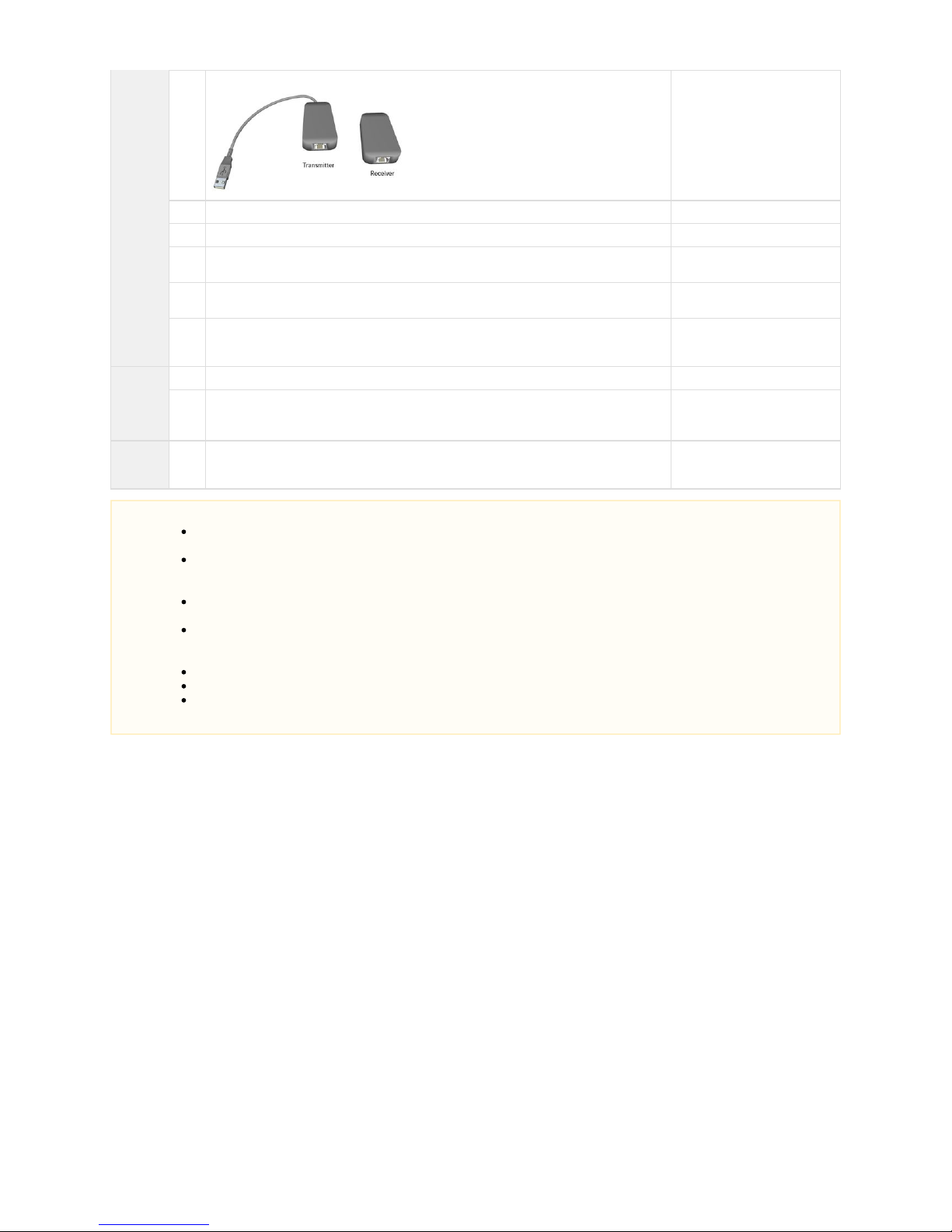
1 USB over UTP Extender (2 parts) 771-00319-00
NOTE: The Extender that comes
with the kit may differ from the
one shown here.
1 CAT5e Ethernet cable, 25 ft 771-00323-00
1 DisplayPort, Male-to-Male, 25 ft 771-00322-00
1 Prysm Label 110-04886-00
To apply to the Base of the stand.
1 USB 2.0 A-Male to B-Male, 6 ft
From the Display carton.
1
sheet
Labels 110-04899-00
To apply to several places on the
Right Stand.
Cables
from the
Right
Display
carton
1 USB 2.0 A-Male to B-Male, 6 ft From the Display carton.
1 IR Extender Cable
From the
Misc.
Parts Kit
1 USB 3.0 Type A Male to Female Extension Cable, 6 ft. 771-00340-00
Cabling Instructions
Assemble the Left Stand and the Right Stand, including the displays, next to each other following the instructions in Section 3.
. For the Right Stand, you will need the extra fastening hardware that comes in the Prysm 85 Dual LCD andAssembly Procedures
Cart carton.
Install the System Cabinet with the X30 only on the Left Stand.
NOTES
The Prysm 85 Dual consists of two Prysm 85 stands and displays. The two displays share a single System Cabinet (that
will contain the X30 and IIC) installed on the Left Stand, linked to the Right Stand with cables.
There will be cables exiting the System Cabinet that will be routed down one of the stand's Support Columns. There will be
other cables that will exit the cabinet to connect directly to the display. Ensure that the cables that go to the display are not
bundled with the other cables.
It is a good practice to label the free ends of the cables that will be routed down a Support Column and out to a specific
source.
The Prysm 85 Dual comes with an extra carton called the Prysm 85 Dual LCD and Cart (050-00355-00) that is essentially
an OPEN ME SECOND carton. It contains parts for the Right Stand and cables to interconnect the components of the two
stands.
A remote control comes with each display. It is important to keep both remotes for display setup.
Make sure you connect an IR Receiver cable (comes with each display) for both displays.
For the purposes of these instructions only, the display stand with the Collaboration System Cabinet is called the Left
and the other stand is called the .Stand Right Stand
Page 70
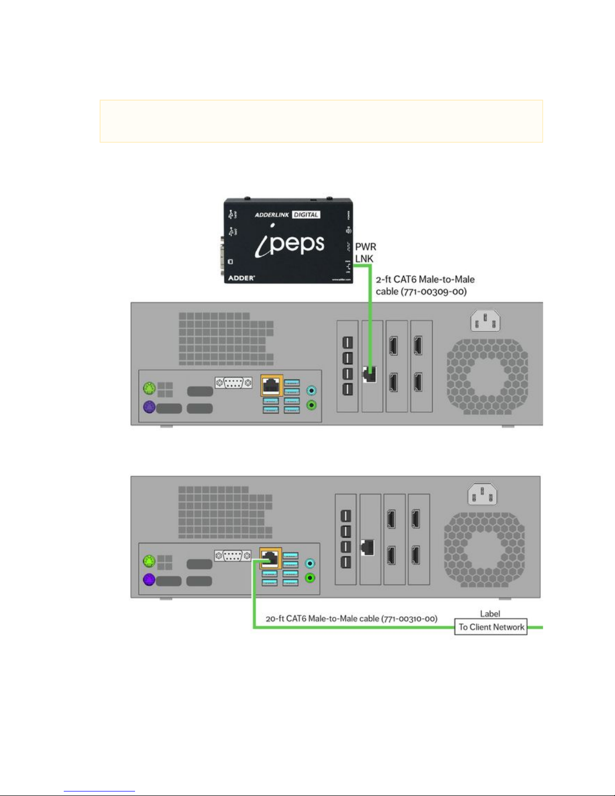
Prysm LCD Visual Workplace Assembly Guide 520-00072-00 Rev 12
70Copyright © 2017, Prysm Inc. All rights reserved. Confidential and proprietary.
1.
2.
a.
b.
3.
a.
b.
Network Cables
Remove the cover from the System Cabinet on the Left Stand.
Connect the 2-foot CAT6 Male-to-Male cable (771-00309-00) as shown here:
Connect one end to the LAN port on the Network Card on the Prysm X30 Application Appliance between the two HDMI
cards.
Connect the other end to the PWR-LNK port on the Adderlink ipeps unit of the IIC.
Connect the 20-foot CAT6 Male-to-Male cable (771-00310-00) as shown here:
Connect one end to the LAN port of the main board of the X30.
Mark the free end of this cable with a label to indicate that it will be connected to the client network.
Note
The following connection is for the optional Interactive Input Controller. If customer order , does not include an IIC
proceed to step 3.
Page 71
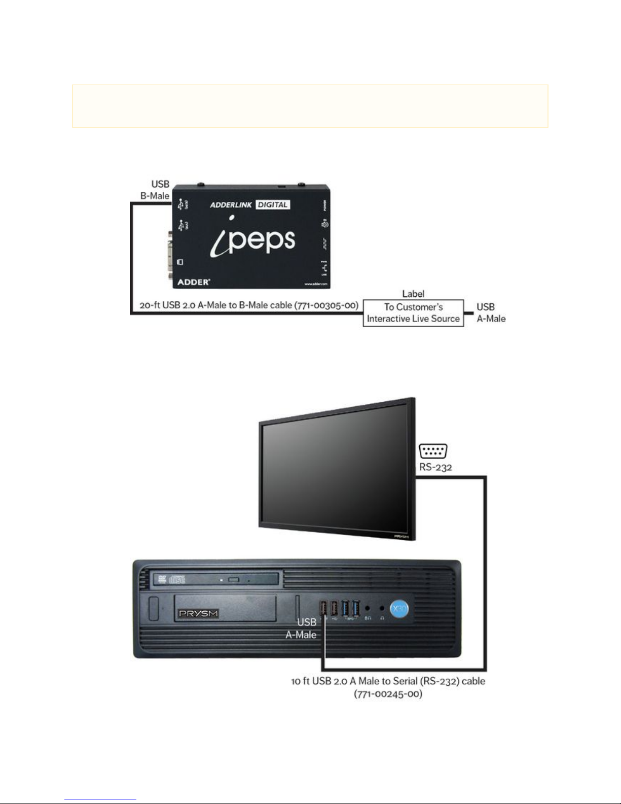
Prysm LCD Visual Workplace Assembly Guide 520-00072-00 Rev 12
71Copyright © 2017, Prysm Inc. All rights reserved. Confidential and proprietary.
1.
a.
b.
c.
2.
a.
b.
c.
Control Cables
Connect the as shown in the illustration below:20-foot USB 2.0 A-Male to B-Male cable (771-00305-00)
Remove the 12-foot USB 2.0 A-Male to B-Male cable from the IIC by disconnecting it from the K/M port on the ipeps unit.
In place of the removed cable, connect the 20-foot USB 2.0 A-Male to B-Male cable (771-00305-00).
Mark the free end of this cable with a label indicating that it will be connected to the customer's Interactive Live Source (such
as a laptop).
Connect the 10-foot USB 2.0 A Male to Serial (RS-232) cable ( as shown here:771-00245-00)
Connect the USB connector to any USB port on the rear panel of the X30.
Route the Serial end through the Left cabinet's grommet hole.
Connect the Serial (RS-232) connector to the RS-232 port on the Right Display.
Note
The following connection is for the optional Interactive Input Controller. If customer order does not include an IIC,
proceed to step 2.
Page 72
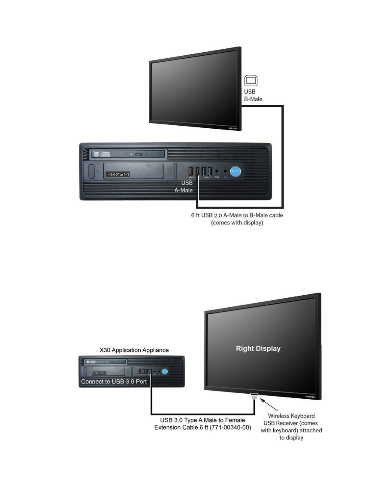
Prysm LCD Visual Workplace Assembly Guide 520-00072-00 Rev 12
72Copyright © 2017, Prysm Inc. All rights reserved. Confidential and proprietary.
3.
a.
b.
c.
4.
a.
b.
c.
d.
e.
Connect the 6-foot USB 2.0 A-Male to B-Male cable ( ) as shown here:comes with display
Connect the USB A-Male connector to USB port on the rear panel of the X30.any
Route the USB-B end through the Left cabinet's grommet hole.
Connect the USB B-Male connector to the USB B-type port on the Right display.
Connect the USB 3.0 Type A Male to Female Extension (771-00340-00) as shown here:
Connect the USB 3.0 Type A Male to Female Extension to the USB port on the front of the Application Appliance.
Route the cable from the Application Appliance through the cabinet and down towards the bottom of the right LCD display.
Connect the wireless keyboard receiver to the end of the USB Extension.
Apply a section of the Velcro Tape (773-00151-00) to the bottom of the right LCD display and the USB Extension cable end
with the receiver.
Attach the USB Extension cable with the receiver to the bottom of the right LCD display.
Page 73
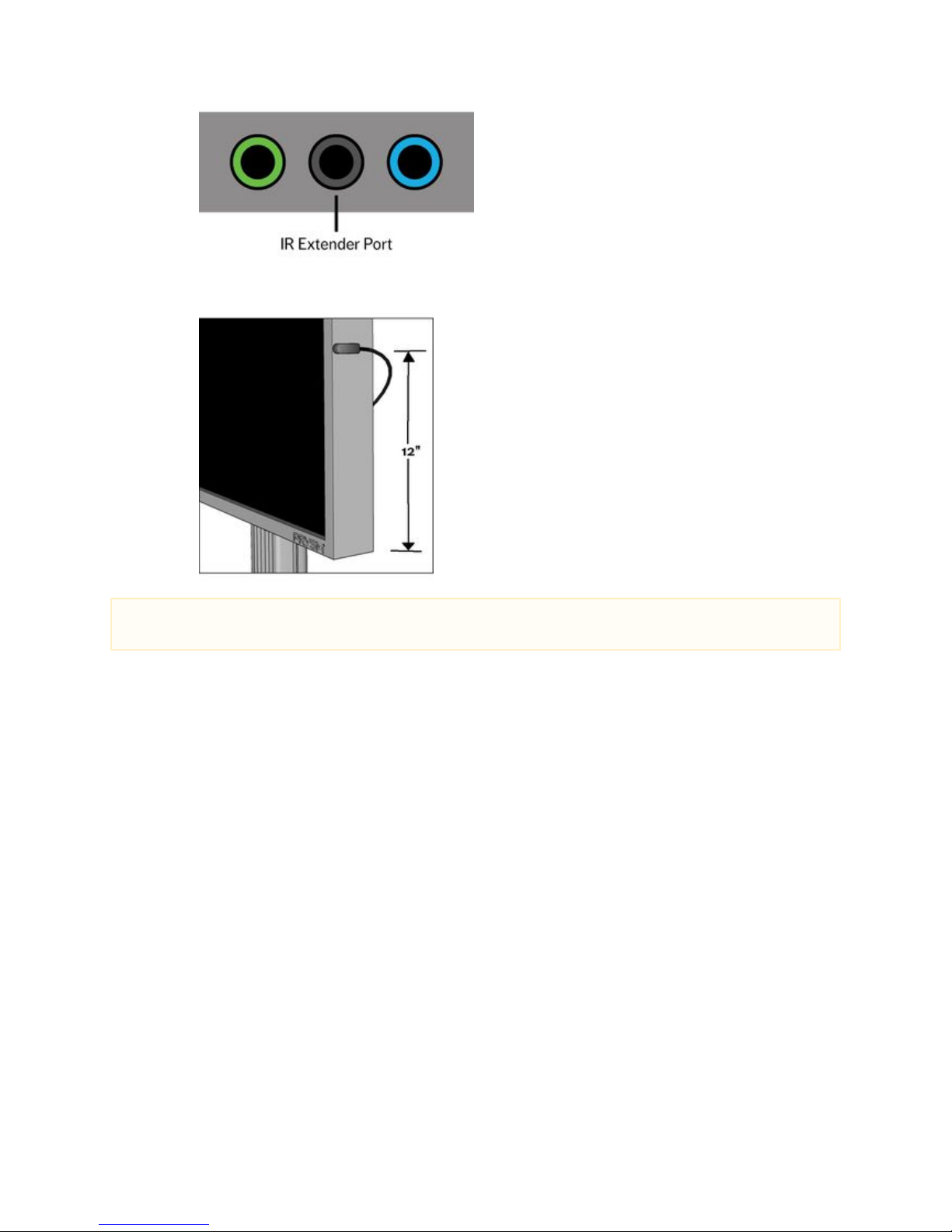
Prysm LCD Visual Workplace Assembly Guide 520-00072-00 Rev 12
73Copyright © 2017, Prysm Inc. All rights reserved. Confidential and proprietary.
5.
a.
b.
Find the two IR Extender Cables. One comes with each display. For each display, connect an IR Extender Cable as shown here:
On the display, connect the IR Extender Cable jack to the round black port.
Connect the IR Receiver to the right side edge of the display as viewed facing the display. Peel the tape off the double stick
material on the IR Receiver and stick the receiver 12" up from the base, making sure the rounded end of the receiver is
facing outward (toward the viewer). For proper reception, do not place the IR Receiver anywhere else on the display.
Important
Make sure you set up the IR Extender for both displays.
Page 74
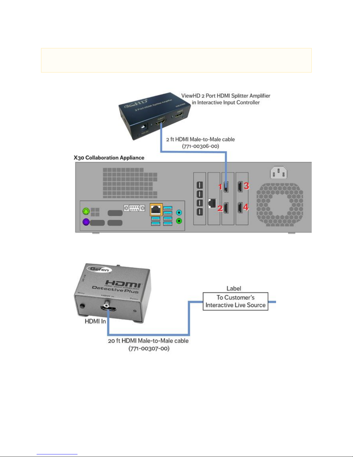
Prysm LCD Visual Workplace Assembly Guide 520-00072-00 Rev 12
74Copyright © 2017, Prysm Inc. All rights reserved. Confidential and proprietary.
1.
a.
b.
2.
a.
b.
c.
Audio-Video Cables
Connect the 2-foot HDMI Male-to-Male cable (771-00306-00) as shown here:
Connect one end to the HDMI In port (HDMI 1) on the X30:
Connect the other end to the Output 1 port on the ViewHD HDMI Splitter Amplifier on the IIC shelf.
Replace the 12-foot HDMI Male-to-Male cable on the IIC as shown here:
Disconnect the cable from the HDMI In port of the HDMI Detective Plus unit.
In it's place, connect the 20-foot HDMI Male-to-Male cable (771-00307-00).
Mark the free end of this cable with a label to indicate that it will connect to the customer's Interactive Live Source (such as a
laptop).
Note
The following two connections are for the optional Interactive Input Controller. If customer order does not include an IIC,
proceed to step 3.
Page 75
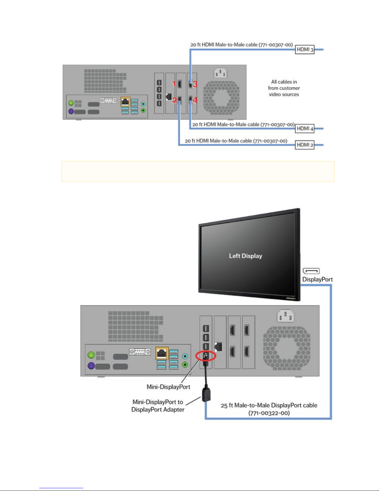
Prysm LCD Visual Workplace Assembly Guide 520-00072-00 Rev 12
75Copyright © 2017, Prysm Inc. All rights reserved. Confidential and proprietary.
3.
4.
a.
b.
c.
d.
Connect the unlabeled end of each cable to the appropriate HDMI port on the rear of the X30 as shown here:
Connect the 25-foot Male-to-Male DisplayPort cable (771- -00) as shown in the illustration below: 00322
Connect one end of the DisplayPort cable to a DisplayPort connection on the Left display.
Route the other end into the cabinet through the cable access hole.
Connect the large end of a L (781-00178-00, comes with X30)ocking Mini-DisplayPort to DisplayPort Adapter into the free
end of the DisplayPort cable.
Connect the small end of the adapter to the Mini-DisplayPort, Port A, in the rear of the X30.
NOTE
The labeled ends of these HDMI cables will eventually go out to the live video sources.
Page 76
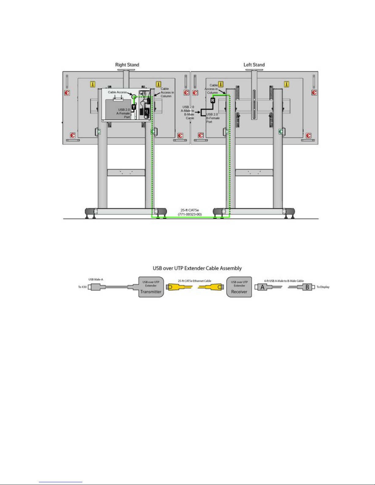
Prysm LCD Visual Workplace Assembly Guide 520-00072-00 Rev 12
76Copyright © 2017, Prysm Inc. All rights reserved. Confidential and proprietary.
d.
1.
a.
b.
c.
d.
e.
f.
USB over UTP Cable
Create and install the USB over UTP Cable Assembly as follows:
Route the 25-foot CAT5e Ethernet cable (771-00323-00) through the Support Columns of the two stands as shown in the
following illustration.
Connect the Left-Stand-end of the CAT5e Ethernet cable to the RJ45 connector on the Transmitter (T) of the USB over UTP
Extender (771-00319-00).
Connect the USB Male-A end of the Extender to a USB 2.0 A-Female port on the rear panel of the X30. (Do use a bluenot
USB 3.0 port.)
Connect the Right-Stand-end of the CAT5e cable to the Receiver (R) of the Extender.
Connect the A-Male end of a 6-foot USB A-Male to B-Male cable (from one of the display cartons) to the Receiver (R) part
of the Extender.
Connect the B-Male end of the USB cable to the USB B-Female port on the display of the Right Stand.
Page 77
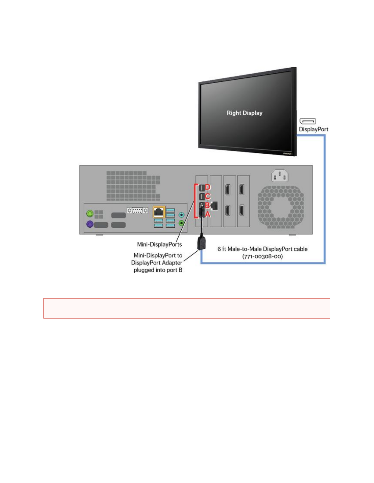
Prysm LCD Visual Workplace Assembly Guide 520-00072-00 Rev 12
77Copyright © 2017, Prysm Inc. All rights reserved. Confidential and proprietary.
2.
a.
b.
c.
d.
e.
1.
2.
3.
4.
5.
Connect the 25-foot DisplayPort cable (771-00322-00) between the x30 and the Right display as shown in the illustration below:
Connect one end of the DisplayPort cable to a DisplayPort connection on the Right display.
Route the other end of the cable down the column following the same path as the previously installed CAT5e cable.
Route the other end into the cabinet on the Left Stand through the cable access hole.
Connect the large end of a L (781-00178-00, comes with X30)ocking Mini-DisplayPort to DisplayPort Adapter into the free
end of the DisplayPort cable.
Connect the small end of the adapter to the Mini-DisplayPort, Port B, in the rear of the X30.
Power Cables
Left Stand
Holding the end of the C13 connectors, feed an outer connector and theAC 3-Way Splitter Cable (771-00312-00) with the three
center connector though the cable access hole the cabinet. Leave the third C13 connector cable outside of the cabinet.into
Connect the C13 connector cable outside of the cabinet directly to the Power In connector near the On/Off switch of the display.
Inside the cabinet, connect the center C13 connector cable from the AC 3-Way Splitter Cable to the Power In port of the X30.
For Optional IIC: Remove the power cable connected to the Power Supply in the Interactive Input Controller. This will not be needed.
For Optional IIC: Connect the other C13 connector cable from the AC 3-Way Splitter Cable to the Power Supply on the Interactive
Input Controller.
WARNING
Make sure no electronic components or power cables of the Prysm Visual Workplace stand are connected to mains power.
Page 78
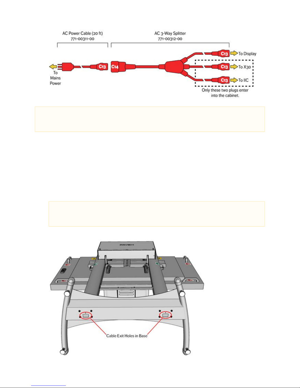
Prysm LCD Visual Workplace Assembly Guide 520-00072-00 Rev 12
78Copyright © 2017, Prysm Inc. All rights reserved. Confidential and proprietary.
6.
1.
2.
1.
2.
3.
4.
5.
Connect the C14 end of the AC 3-Way Splitter Cable to the 20 ft AC extension cable (771-00311-00).
Right Stand
Connect the C13 connector of the 2nd power cable (771-00311-00) directly to the Power In connector near the On/Off switch of the
display.
Feed the other end of the cable into a grommet hole in one of the columns and down through the base.
Cable Routing
Gather all cables that are to be routed out to sources.
Feed the cables installed previously in the cabinet out through the cable access hole in the back of the cabinet shelf.
To feed the cables down one of the columns of the Left Stand, gather the ends so that none of the connectors is next to each other.
If the connectors are bunched up they won't go through the column's grommet hole.
Using two people, have one person feed the cables down the hole while the other person pulls the cables down from the column
hole on the underside of the stand base. Carefully pull them all the way through.
Once all cables are through, connect each cable at it's appropriate destination, including the power cable.
NOTE
The Prysm Visual Workplace systems accept voltages between 100v and 240v. However, the 20 ft power cable that comes with
this product (771-00311-00) has a 5-15P type plug used for 110v receptacles. If the customer site does not have this type of power
or receptacle, the customer must supply an adapter for the supplied cable, or a replacement cable.
NOTE
The plastic grommets in the Support Columns have a tendency to push through and get lost in the columns. It is best to
remove the grommet on the hole into which you will be feeding the cables. Also, take care not to damage cables by
dragging them against the rough edge of the grommet holes.
Page 79

Prysm LCD Visual Workplace Assembly Guide 520-00072-00 Rev 12
79Copyright © 2017, Prysm Inc. All rights reserved. Confidential and proprietary.
Disable USB to Serial
Once all cables are routed, disconnect the USB end of the USB to RS-232 cable from the rear of the X30. It is not to be(771-00245-00)
connected until it is necessary to update the firmware of the display.
The cabling is complete. Proceed to 5. Startup Configuration.
Page 80
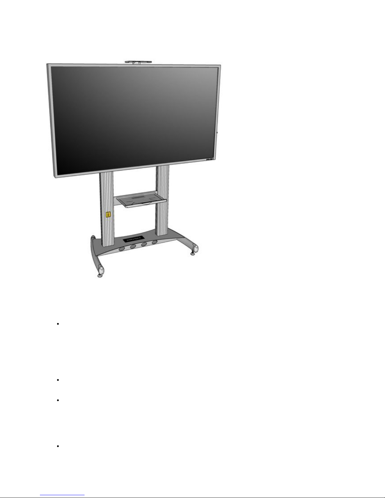
Prysm LCD Visual Workplace Assembly Guide 520-00072-00 Rev 12
80Copyright © 2017, Prysm Inc. All rights reserved. Confidential and proprietary.
5. Startup Configuration
The Prysm LCD Visual Workplace stand assembly is complete.
Verify and/or Update Display Firmware
To ensure that the display has the most current firmware installed and to install it, refer to:
Prysm 98, 85, 65, and 65 Core Firmware Update Procedure (230-00467-00).
Lock the On Screen Display (OSD)
After verifying or updating the Display Firmware the OSD should be locked to prevent tampering of display settings.
To lock the remote control and keypad:
Press , , , , , and on the remote control or keypad.Enter Enter Exit Exit Enter Exit
To unlock the remote control and keypad:
Press , , , , , and on the remote control or keypad.Enter Enter Exit Exit Enter Exit
System Configuration and Testing
The next steps involve For these procedures, refer to:software configuration and testing.
stallation GuideApplication Appliance In (520-00064-00)
 Loading...