

Page 1

Microcontroller-controlled temperature difference controller for solar thermal systems
Operating manual
Sunny Scout 1328
Page 2
2
Content
1 Application area / device features 3
1.1 Application area 3
1.2 Device features 3
2 Safety instructions 3
3 Mounting the device 4
3.1 Opening the device 4
3.2 Wall mounting 4
3.3 Connections 4
3.4 Temperature sensor connection 4
4 Short descriptions and device operation 5
4.1 Display layout 5
4.2 Operating the device 5
5
Menu structure 6
5.1 "Info" menu 6
5.4 "Basic Setup" menu 6
6 System diagram 7
7 Controller functions 8
7.1 General controller functions 8
7.1.1 Temperature dierence
8
7.1.2 Thermostat 8
7.1.3 RPM control
8
7.2 Protective functions 8
7.2.1 Anti-freeze protection (Jumper=on) 8
7.2.3 System protection 8
7.2.3 Pump blocking protection 8
8 System monitoring 9
8.1 Sensor monitoring 9
8.2 Flow monitoring 9
9 Troubleshooting 9
9.1 Faults with error messages 9
9.2 Faults without error messages 10
10 Specications 11
11 Resistance table PT1000 11
12 Warranty conditions 12
13 Declaration of conformity 12
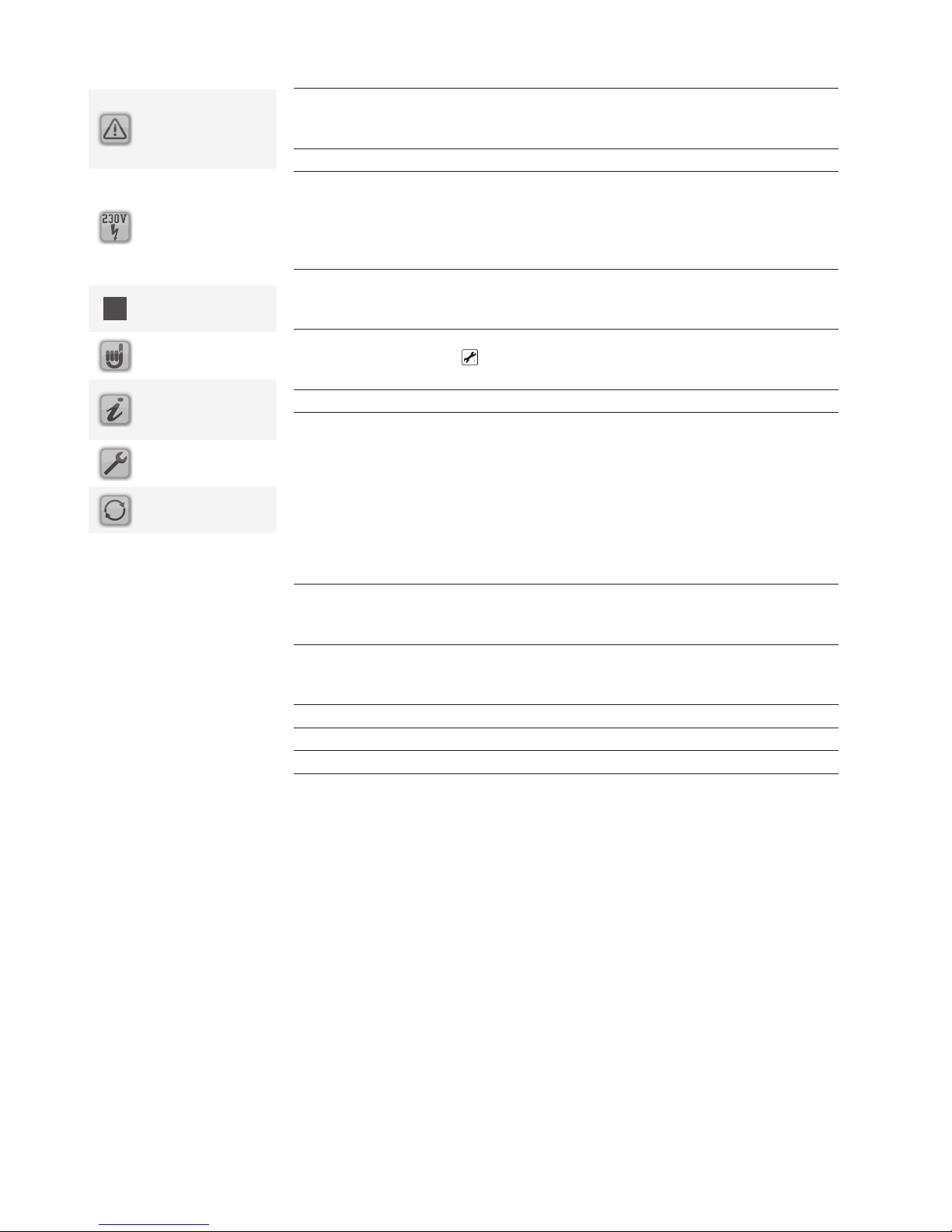
Explanation of the
graphic symbols
Attention!
Symbol indicates
possible dangers
and errors
Attention 230V~
voltage!
Symbol indicates
risks posed by
lethally high voltages.
List
Please note!
Information for
handling / special
features
Implementation /
procedure
Test /
check
Page 3

3
1 Application area / device features
1.1 Application area
The Sunny Scout 1328 controllers are high-performance microprocessor-controlled
units for controlling the functions of solar thermal systems. The Sunny Scout 1328
controls solar power systems equipped with one collector and one storage tank.
The controllers are designed for use in dry rooms as well as residential, business
and commercial applications. Prior to commissioning the device, make sure to
verify that the intended use complies with the applicable regulations.
1.2 Device features
The Sunny Scout 1328 controller is equipped with the following features:
Operating menu with graphic symbols ◼
Automatic display of the temperature values ◼
No manual operation needed ◼
Extensive functions for system monitoring that display symbols to indicate er- ◼
rors and faults. Additionaly LED indicators.
Storage of all values even during a prolonged mains power supply outage ◼
Various protective functions, such as system protection, collector protection, ◼
anti-freeze and ow monitoring
Available accessories:
Temperature sensor PT1000 ◼
Sensor connection box ◼
Immersion sleeves ◼
2 Safety instructions
Always completely disconnect the device from the operating voltage before ◼
performing installation or wiring work on the electrical equipment.
Never mix up the connections of the protective low voltage areas (sensors) with
the 230V connections. Otherwise, the device will be destroyed. The device and
the connected sensors may carry deadly voltages.
Solar power systems can reach high temperatures. Such temperatures pose a ◼
risk of burns! Exercise caution when installing the temperature sensors!
Mount the Sunny Scout 1328 controller in a position where it will not be sub�ect-Sunny Scout 1328 controller in a position where it will not be sub�ect- controller in a position where it will not be sub�ect- ◼
ed to excessive operating temperatures (> 50°C) by any external heat sources.
For safety reasons, the system may only remain in manual operation for testing
purposes. In this operating mode, the system does not monitor for maximum
temperatures and sensor functions. If there is any recognisable damage to the
controller, cables or the connected pumps and valves, the system must not be
started.
All installation and wiring
work must only be carried
out on the controller when the
device is disconnected from the
power supply.
The Sunny Scout 1328 must only
be connected and commissioned
by qualified personnel. In doing
so, the applicable safety regulations must be observed.
Page 4
4
3 Mounting the device
3.1 Opening the device
Prior to opening the device, make sure to disconnect the mains voltage and ensure
that it cannot be switched back on again.
3.2 Wall mounting
Secure the controller on the wall. Tighten all screws only as tight as necessary to
prevent damage to the lower part of the housing.
3.3 Connections
The following points must be followed for the 230V connections:
◼ In case of a xed mains connection, there must be a switch installed outside
the controller that can disconnect the device from the mains power supply. This
switch is not required if the mains supply is connected using a cable and an
earthed mains plug.
The controllers are designed to operate using a 230V/50Hz. The pumps and ◼
valves to be connected must be designed for this voltage!
All protective conductors must be connected to terminals marked with PE. ◼
The neutral conductor terminals (N) are electrically connected and are not ◼
switched!
The switching output (A1) is electronic 230V~ N/O contact. If potential-free ◼
contacts are required, the appropriate corresponding accessories are available.
3.4 Temperature sensor connection
The Sunny Scout 1328 devices use PT1000 precision platinum temperature sensors.
Mounting / wiring the temperature sensors:
◼ Mount the sensors on the collector and the storage tank. Ensure proper heat
transfer and use heat-conducting paste if necessary.
Cross-sections for cable extensions (shielded): ◼
- up to 15m 2 x 0.5mm2,
- up to 50m 2 x 0.75mm2.
The shield is connected to the earth (PE)
Connect the temperature sensors according to the system diagram. The polarity ◼
of both conductors for the temperature sensors is irrelevant.
◼ Sensor cables must be laid separately from 230V wires.
Sensor connection boxes equipped with surge protection should be used for ◼
collector sensors and cable extensions.
The controller must only
be installed in dry and
non-explosive areas. Mounting
the controller on an inflammable
surface is prohibited
Page 5
5
4 Short descriptions and device operation
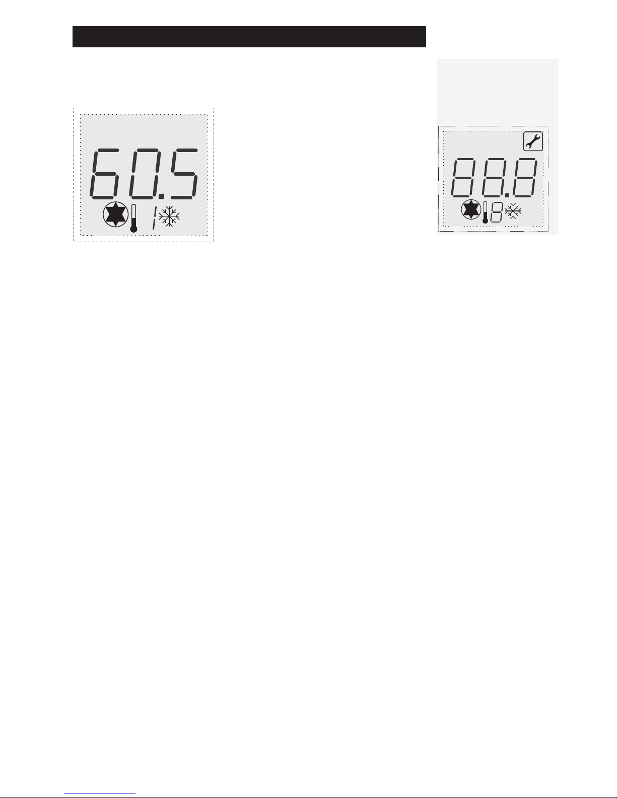
4.1 Display layout
During actual operation, these symbols are only displayed for selection once
depending on the menu position.
Active menu in the menu levels ◂
Allocation of the current display ◂
Current measured values, times or control- ◂
ler states: here 60,5C°.
Measuring point ◂
Controller state/messages ◂
4.2 Operating the device
The controller is equipped with a micro button that can be operated through a
small hole in the right side of the housing using a suitable tool.
Briey pressing the button switches the controller from the “Info” menu to the
“Basic Setup” menu. Here, you can scroll through and select the variables and information by pressing the button once.
To change the selected variable, the button must be pressed for approximately 2
seconds until the value ashes. This value is increased up to the end of the range by
pressing the button again. Afterwards, the value �umps to the smallest value that
can also be increased again.
To store a value, the button must be pressed again for approximately 2 seconds.
Display symbols
All possible display symbols are
shown below.
stopstart
dTminmax
X
Page 6
6
5
Menu structure
5.1 "Info" menu
The following measured values are displayed automatic in the Info menu:
Display
e.g.
Meaning Can be reset
75 °C
Displays current collector temperature
No
52 °C
Displays current storage tank temperature
No
5.4 "Basic Setup" menu
The hydraulic diagrams and additional functions are displayed in the Basic Setup
menu. Settings must only be changed by a specialised technician.
Display
e.g.
Meaning Value range
Factory
setting
Current
setting
max
65 °C
Storage tank:
Maximum permissible temperature
15 – 95°C 60°C
dT max
7 K
Storage tank:
Switch-on dierence
3 – 40K 10K
dT min
3 K
Storage tank:
Switch-o dierence
2 – 35K 5K
Tmin
Absolute treshold - Minimum
temperature at which temp.
dierence is analysed
5..90 10°C
on
Manually switching on / o the
switching output A1 (pump 1)
0 = o
1 = on
0
RES
Reset the values to the factory
setting
V1.1 Software release
Menü „Info“
Settings and changes in
this menu must only be
carried out by a specialised
technician. Incorrect settings can
damage or adversely affect the
function of the solar power system.
Page 7
7
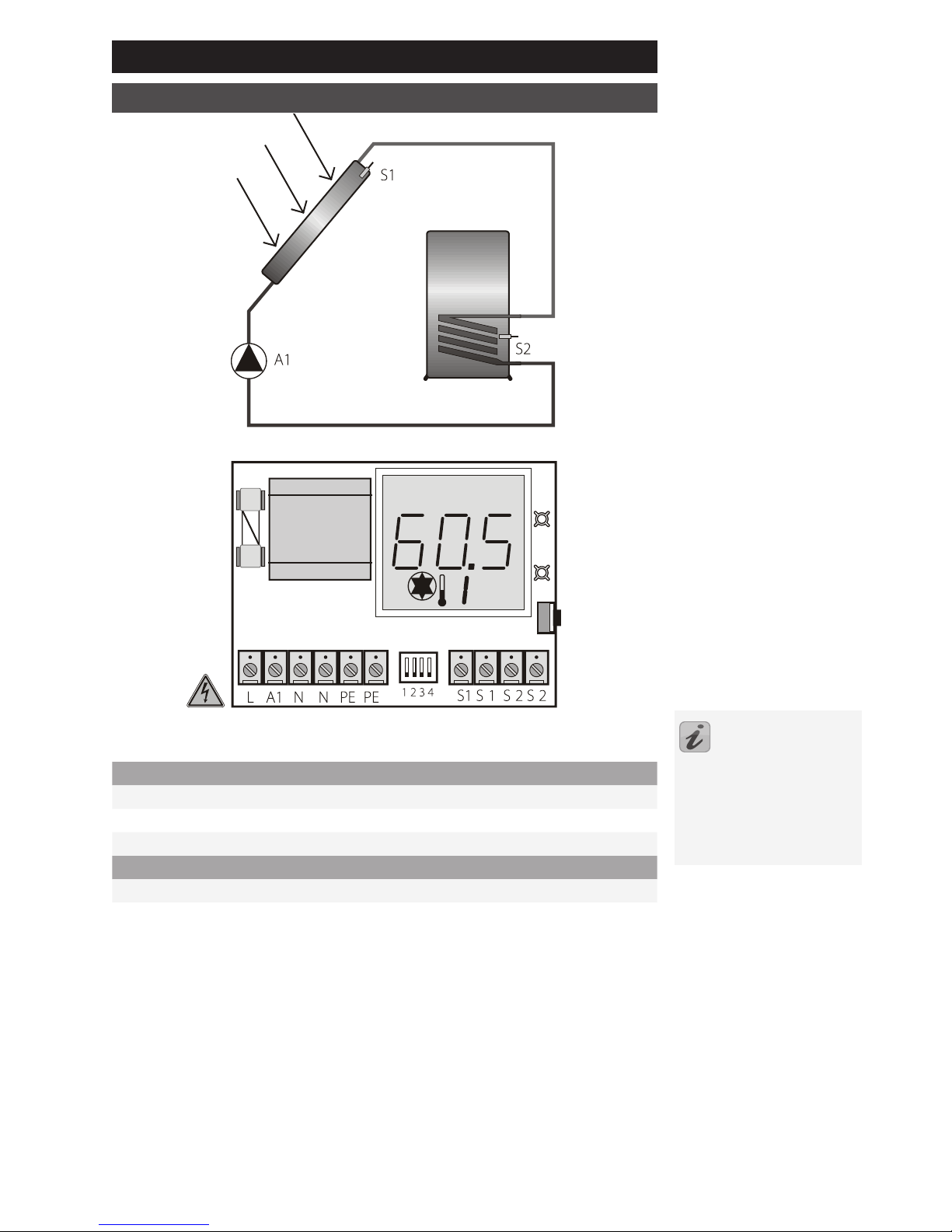
6 System diagram
1 collector, 1 storage tank
230V connections
L Mains phase
N Neutral conductor - mains and outputs
A1 Solar circuit pump (switching output 1)
Sensor connections
S1 Collector sensor
S2 Lower storage tank
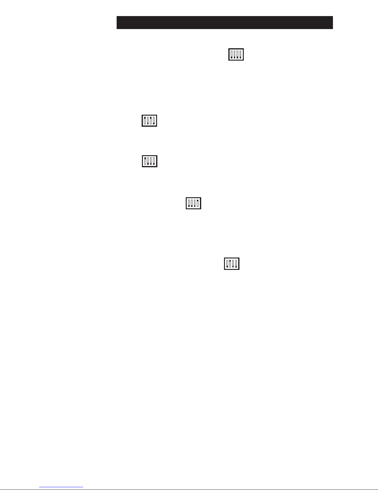
Switch positions:
Temp. diff. controller: all=off
Heating: 1=on
Cooling: 1 and 3=on
Anti-freeze: 2=on
RPM-control: 4=on
Page 8
8
7 Controller functions
7.1 General controller functions
7.1.1 Temperature dierence
The controller compares the temperatures of the various measuring points and optimally charges the storage tank. If the collector temperature exceeds the storage
tank temperature, the solar circuit pump is switched on. Monitoring and protection
functions ensure safe operation.
7.1.2 Thermostat
- Cooling
If the measured temperature exceeds the target value, output A1 is switched on
until the measured temperature falls below the target value - hysteresis (e.g. 60°C
- 10K).
- Heating :
If the measured temperature falls below the target value, output A1 is switched on
until the measured temperature reaches the target value + hysteresis (e.g. 60°C +
10K).
7.1.3 RPM control
The output A1 can be operated using an RPM control.
Minimum - 30 %
7.2 Protective functions
The controller is equipped with the following protective functions.
7.2.1 Anti-freeze protection
This function must be activated if the water or glycol mixture can freeze. If the temperature of the collector sensor drops below 5°C, the solar circuit pump is activated
and heats the solar circuit using the heat exchanger in the storage tank.
7.2.3 System protection
If the collector temperature exceeds 130°C, the solar circuit pump is switched o to
protect the system components.
If the collector temperature drops below 120°C, the solar circuit pump is switched
on. This function is always activated.
7.2.3 Pump blocking protection
If the solar power system is out of commission for an extended period of time due
to poor weather, for example, the solar circuit pump may “seize”. To prevent this, the
controller switches the pump on for 30 seconds after 10 days.
Page 9
9
8 System monitoring
8.1 Sensor monitoring
The connected sensors and sensor cables are monitored for interruptions and
short-circuits. Errors are indicated by the symbol. You can nd the error source
by scrolling up or down the Info menu.
8.2 Flow monitoring
The controller is programmed to display a message if the ow is interrupted, e.g.
pump fault or if vapour is in the system. This message, however, does not switch o
the pump.
9 Troubleshooting
System faults are distinguished into two general categories:
Faults that are automatically detected by the controller and therefore can be ◼
displayed using error messages
Faults that the controller cannot detect ◼
9.1 Faults with error messages
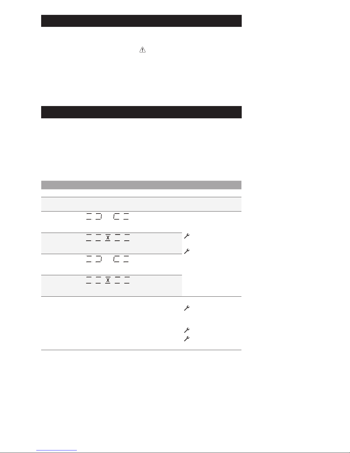
LED‘s Display Meaning Measures
LED green is on Power on ◼ -
LED green
ashes
Pump is ON ◼ -
LED red ashes:
1 x
Collector sensor ◼
cable is interrupted
Check wiring /
replace it
Check sensor
resistance and
replace sensor if
necessary
LED red ashes
2 x
Short-circuit in ◼
the collector
sensor cable
LED red ashes:
3 x
Storage sensor ◼
cable is interrupted
LED red ashes:
4 x
Short-circuit in ◼
the storage sensor cable
LED red is on no ow ◼
Error in the ◼
pump connection
Pump defective ◼
Air in the system ◼
Check cable
Replace pump
Deaerate the
system
Page 10
10
9.2 Faults without error messages
Faults and malfunctions that cannot be displayed as well as possible causes and
their error source can be identied using the following table. If you cannot remedy
the fault using the description below, contact the supplier or installer.
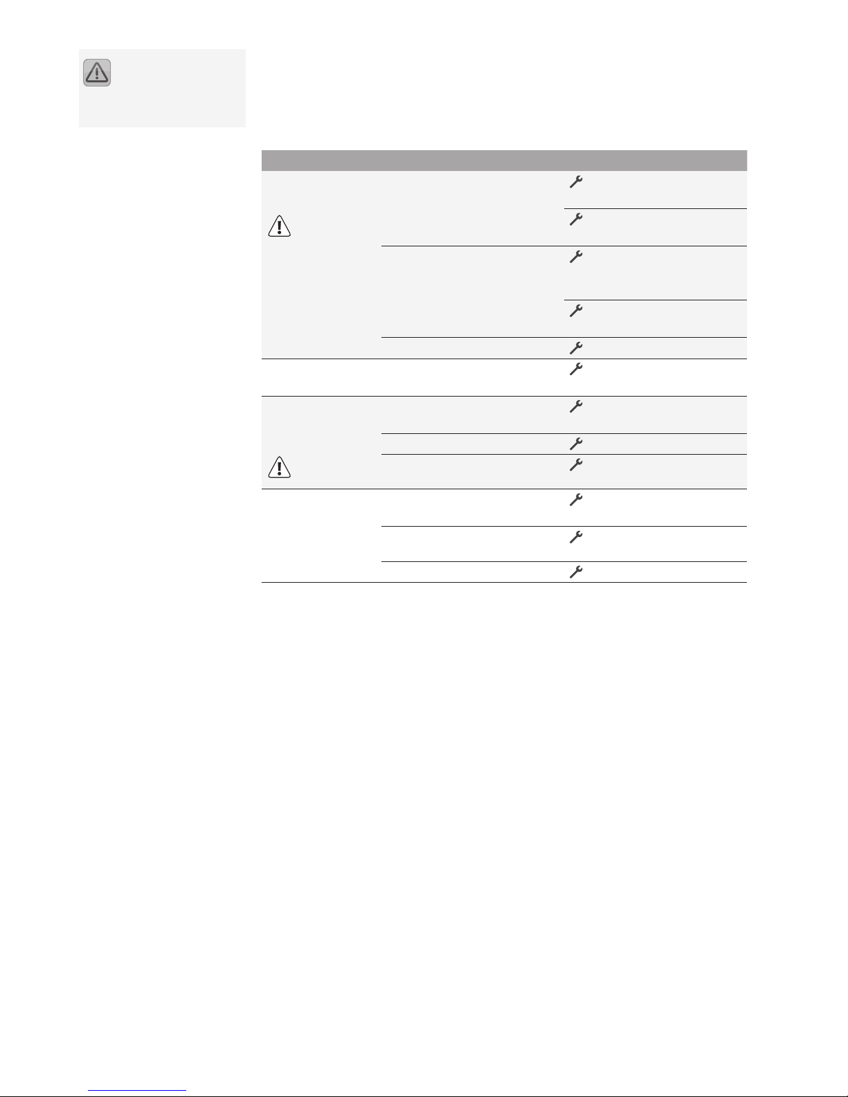
Problem Possible causes Measures
Display does not
function
230V mains voltage not ◼
available
Switch on or connect
controller
Check the connection's
main fuse
Defective fuse inside the ◼
device
Check the fuse*,
replace with a new type
2A/T, if necessary.
Check the 230V compo- Check the 230V compo-Check the 230V compo-
nents for short-circuits
Defect device ◼
Contact the supplier
Output is not
switched on
Switch-on condition is not ◼
fullled.
Wait until switch-on
condition is satised.
"Pump" symbol
rotates, but the
pump is not on
Connection to the pump ◼
interrupted.
Check the cable leading
to the pump
Pump is blocked. ◼
Free the pump
No voltage present at the ◼
switching output.
Contact the supplier.
Temperature
display strongly
uctuates at short
intervals
Sensor cables are installed ◼
near the 230V cables
Relocate sensor cables,
shield sensor cables
Long sensor cables ex- ◼
tended without shielding
Shield sensor cables
Defect device ◼
Contact the supplier
Faults that affect the
230V/A mains power
supply must only be remedied by
a specialist!
Page 11

11
10 Specications
Housing
Material
100% recyclable ABS housing for wall mounting
Dimensions W x H x D in mm,
weight
95 x 75 x 50;
approx. 130 g
Protection class
IP20 according to DIN 40050, IEC 529, VDE
0470, EN 60529
Electrical specications
Operating voltage AC 230 Volts, 50Hz, -10 – +15%
Radio interference level N according to VDE 0875
Max. cable cross-section
230V connections
2.5 mm² ne-wire/single wire
Temperature sensor
measuring range
PT1000, 1 kΩ at 0°C
-30°C .. +250°C
Rated impulse voltage
4 kV according to EN 60730/DIN, VDE 0631, IEC
60664/IEC
Output Voltage
Power - switching output
230V~
1A / approx. 230VAfor cos φ = 0,7-1,0
Fuse protection
Fine-wire fuse 5 x 20mm, 2A/T
(2 amperes, delayed-action fuse)
Miscellaneous
Operating temperature 0 – 50°C
Storage temperature -10 – +65°C
Humidity max. 60 %
11 Resistance table PT1000
The temperature sensors can be checked for proper function using the following
temperature resistance table and an ohmmeter:
Temperature
in °C
Resistance
in Ohm
Temperature
in °C
Resistance
in Ohm
-30 882 60 1232
-20 921 70 1271
-10 960 80 1309
0 1000 90 1347
10 1039 100 1385
20 1077 120 1461
30 1116 140 1535
40 1155 200 1758
50 1194
Subject to change in
accordance with technical
advances!
Page 12

12
12 Warranty conditions
The Sunny Scout 1328 controllers are carefully produced and tested on an auto-Sunny Scout 1328 controllers are carefully produced and tested on an auto- controllers are carefully produced and tested on an automatic testing station. If any failures occur, rst check if there are any operation /
setting or system errors. Furthermore, check the pump and temperature sensor
connections.
PROZEDA GmbH provides a 2-year warranty starting at the date of purchase and
according to the following conditions.
a) The warranty comes into eect if the purchased good exhibits a material or
quality defect. If the defect is caused by improper handling, by exceeding the
permitted values stated in the specications, improper wiring, invalid technical
modications to the device performed by the buyer or by an another company
other than PROZEDA GmbH, the warranty shall be void.
b) The warranty requires a written notice that describes the defect in detail as well
as a copy of the customer invoice.
PROZEDA GmbH can choose to full the guarantee, at its own discretion, by one
of the following measures
- Repair (reconditioning) or
- Delivery of a fully functional replacement product
The device shall be repaired within 1 month after PROZEDA GmbH has received
it.
If the device is not repaired within the two repairs attempts, the buyer is entitled to delivery of a fully functional replacement product.
If a replacement product is delivered, a new warranty that corresponds to these
conditions shall come into eect.
c) Any further warranty (redhibitory action, reduction of price) is excluded.
Warranty claims may only be submitted by the customer and are non-transferable.
If a defect occurs during the warranty period, please contact the supplier / installer.
When returning the device for warranty service, please make sure to send a description of the error and, if possible, the system diagram along with the wiring diagram.
13 Declaration of conformity
We, Prozeda GmbH, declare under our sole responsibility that the Sunny Scout type
1328 product complies with the following standards:
DIRECTIVE 2004/108/EC OF THE EUROPEAN PARLIAMENT AND OF THE COUNCIL
of 15 12.2004 on the approximation of the laws of the Member States relating to
electromagnetic compatibility and repealing Directive 89/336/EEC
Law on the electromagnetic compatibility of equipment (EMC) of 26 February 2008
DIRECTIVE 2006/95/EC OF THE EUROPEAN PARLIAMENT AND OF THE COUNCIL of
12 December 2006 on the approximation of the laws of the Member States concerning electrical equipment for use within certain voltage limits
DIN EN 61326-1, VDE 0843-20-1:2006-10 Electrical measurement, control and laboratory use - EMC requirements - Part 1: General requirements (IEC 61326-1:2005);
German version EN 61326 -1:2006
DIN EN 61326-2-2, VDE 0843-20-2-2:2006-10 Electrical measurement, control and
laboratory use - EMC requirements - Part 2-2: Particular requirements - Test, operating conditions and performance requirements for portable test, measurement and
monitoring equipment for use in low voltage power supply systems (IEC 61326-22:2005); German version EN 61326-2-2:2006
Operating manual for Sunny Scout 1328 04/2009
 Loading...