

Page 1

Heating circuit and solar controller
grandis 650 HK
Menus and controller functions
English version of original German installation and operating instructions
Version: 1.2
January 2016
Page 2

This manual is designed to help you use the controller properly, safely and economically.
This manual represents only a part of the installation and operating instructions.
Read the document before making any settings on the controller. Installation and
operating instructions.
Target group
This manual is addressed to all persons who carry out any of the following tasks:
• Installing the controller
• Connecting the controller
• Putting the controller into operation
• Setting the controller
• Maintaining the solar power system
• Eliminating faults on the controller and the solar power system
• Disposing of the controller
These persons must have the following knowledge and skills:
• Knowledge about establishing electrical connections
• Knowledge about the hydraulic operation of solar power systems
• Knowledge of the applicable regulations at the point of use and the ability to apply
them
These persons must have read and understood the contents of this manual.
Availability
This manual is part of the controller. Always keep it in an easily accessible location. Include
this manual with the controller should the controller change hands.
If this manual gets lost or becomes unusable, you can contact the manufacturer for a new
copy.
Page 3
DANGER
WARNI
NG
CAUTION
ATTENTION
Style conventions used in the text
Specific style conventions are assigned to different elements in the manual. This makes it
easy to recognise the type of text concerned:
Standard text,
"Menu", "Menu item", "Button designations",
• lists and
actions.
Notes accompanied by this symbol contain information about how to operate the
controller economically.
Style conventions for hazard warnings
This manual makes reference to the following categories of hazard warnings:
Information or instructions accompanied by the word DANGER provide a
warning about a hazardous situation that will lead to fatal or serious
injuries.
Style conventions for warnings of damage to property or
the environment
Information or instructions accompanied by the word WARNING provide a
warning about a hazardous situation that may possibly lead to fatal or
serious injuries.
Information or instructions accompanied by the word CAUTION provide a
warning about a situation that can lead to minor or moderate injuries.
Information and instructions of this kind provide a warning about a
situation that can lead to damage to property or the environment.
Page 4

Table of contents
1 Displaying and changing the values in the menus ................................................. 6
1.1 Displaying values in the "Info" menu ............................................................................................. 6
1.2 Displaying and changing values in the "Program" menu ...................................................... 13
1.3 Controlling switching outputs in the "Manual mode" menu ............................................... 19
1.4 Displaying and changing values in the "Basic settings" menu ............................................ 20
2 "Heating circuit" function ...................................................................................... 28
2.1 Mixed heating circuit ........................................................................................................................ 28
2.2 Unmixed heating circuit .................................................................................................................. 29
2.3 Switching the heating circuit pumps off and on ...................................................................... 30
2.4 Hot water .............................................................................................................................................. 30
2.5 Putting the heating circuits into operation ............................................................................... 31
2.6 Screed heating .................................................................................................................................... 31
2.7 Room sensor (RS) ................................................................................................................................ 32
3 “Solar” function...................................................................................................... 33
3.1 Setting the charging method ......................................................................................................... 33
3.2 Setting the "Storage tank priority" function .............................................................................. 33
3.3 Setting the "Parallel charging" function ...................................................................................... 34
3.4 Setting the pump control system ................................................................................................. 35
3.5 Setting the "Tube collector" function .......................................................................................... 37
3.6 Bypass function / external heat exchanger ................................................................................ 37
4 Setting protective functions .................................................................................. 38
4.1 Setting the "Collector protection" function ............................................................................... 38
4.2 "Storage tank protection" function .............................................................................................. 38
4.3 "System protection" function ......................................................................................................... 39
4.4 "Pump protection" function............................................................................................................ 39
4.5 "Heat exchanger protection" function ........................................................................................ 39
4.6 Setting the "Recooling" function ................................................................................................... 39
4.7 Setting the "Drain-back" function ................................................................................................. 40
4.8 Setting the "Anti-freeze" function ................................................................................................. 41
5 Measuring the energy yield ................................................................................... 41
5.1 DFG (flow sensor) ............................................................................................................................... 42
5.2 VFS (vortex flow sensor) ................................................................................................................... 42
5.3 DFA (flow indicator)........................................................................................................................... 42
6 Setting multi-function controllers (MFC) .............................................................. 43
6.1 Setting the "Cooling" function ....................................................................................................... 43
6.2 Setting the "Heating" function ....................................................................................................... 44
6.3 Setting the "Temperature difference controller" function .................................................... 44
6.4 Setting the "Threshold value switch" function ......................................................................... 45
Page 5

Setting the "Return line boost" function .................................................................................... 45
6.5
6.6 Setting the "Wood-fired boiler" function ................................................................................... 45
6.7 Setting the "Circulation" function ................................................................................................. 45
6.8 Setting the "Alarm" function .......................................................................................................... 46
6.9 Setting the "Timer" function ........................................................................................................... 46
6.10 Setting the "HW reheating" function ........................................................................................... 46
6.11 Setting the "Temperature range" function ................................................................................ 47
6.12 Setting the "Modulation" function ............................................................................................... 47
6.13 Setting the "Cascade" function ...................................................................................................... 47
6.14 Setting the "Yield" function ............................................................................................................ 48
6.15 Setting the "Mixer" function (only MFC 1) .................................................................................. 48
6.16 Setting the "Valve" function (only MFC 2) .................................................................................. 49
6.17 Setting the "Storage tank cooling" function (only MFC 3) .................................................... 49
6.18 Setting the logical link ...................................................................................................................... 50
Page 6
Displaying and changing the values in the menus
6
1 Displaying and changing the values in the
menus
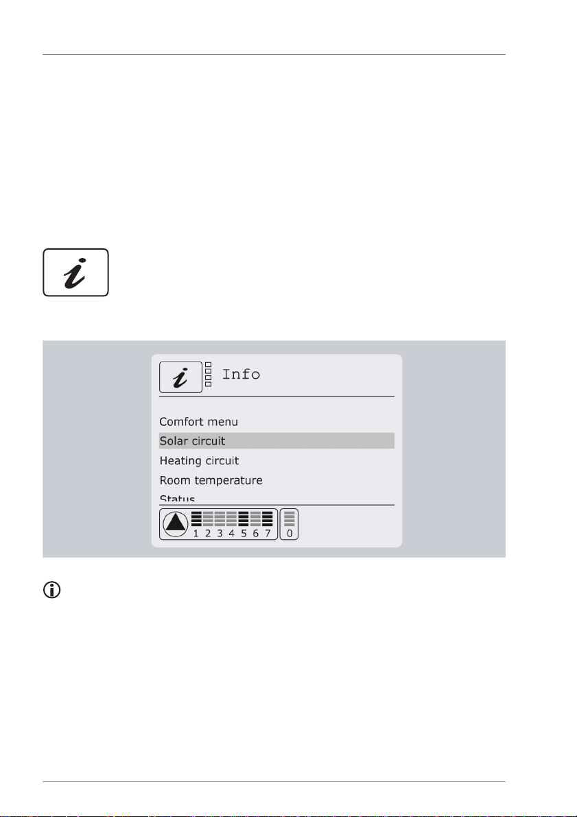
This chapter provides an overview of the menus and menu items. Menu items for the first
menu level are displayed in bold. Menu items for the second menu level are displayed
beneath in standard text.
1.1 Displaying values in the "Info" menu
The "Info" menu allows you to display measurement and output values and status
messages.
Depending on which additional functions have been activated, not all values will
necessarily be displayed.
Page 7
Displaying and changing the values in the menus
7
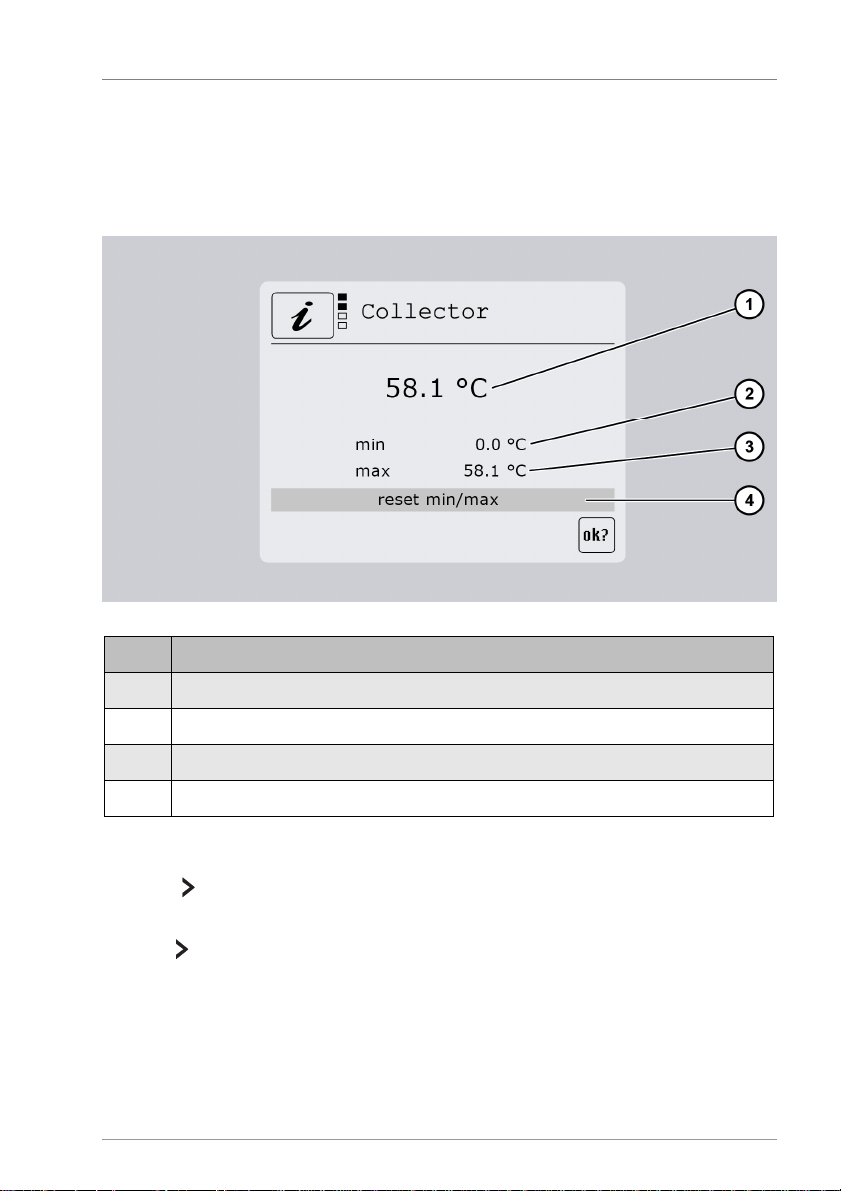
Pos. Description
1 Current measured value
2 Display of the minimum value reached
so far
3 Display of the maximum value reached so far
4 Reset the minimum and maximum values to the current measurement value
Solar circuit
This menu allows you to display measurement values in the solar circuit and to reset them
to the current measurement value. In this case the terminal designation precedes the
designation for the sensor (e. g. S01: Collector). Whenever you activate a menu item, the
"Measurement value" display screen will be displayed.
To reset a value, proceed as follows:
Select .
The OK symbol will be displayed.
Press to confirm.
The value will be reset.
Page 8

Displaying and changing the values in the menus
8
Item Description
1 Room temperatures 1 to 3 for each heating circuit. Room actuators are shown as a
switch symbol.
2 Assignment to the activated heating circuits
Heating circuit
In this menu you can view the measured values (1 and 2) in the heating circuits. In this
case the terminal designation precedes the sensor designation (e.g. S10: Outdoor
temperature). When you activate a menu item, the min and max values previously
obtained will appear and you can reset to the current measured value.
Room temperature
This menu is visible only when you have activated at least one room user terminal (navo
400), room sensor or room actuator.
Page 9
Displaying and changing the values in the menus
9
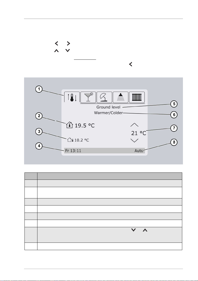
Item Description
1 Active menu (here: "Warmer/Colder" menu)
2 Room temperature. This stands for the current temperature in the room where the room
user terminal is located.
It appears only when navo 400 is connect
ed.
3 Outdoor temperature
4 Day and time
5 Heating circuit designation (here: heating circuit on "Ground level")
6 Menu designation (here: "Warmer/Colder" menu)
7 Target temperature. This can be changed with the button
or .
correction will appear in the range
-
10 to +10.
8 Current operating status (here: "Auto")
"Comfort" menu
In this menu you can enter changes. Select heating functions are clearly presented and
the parameters can be changed quickly and conveniently.
Use the buttons or to select the required menu.
Use the buttons or to increase or decrease the value in steps.
The change will be adopted immediately.
The "Comfort" menu can be closed by pressing the button in the "Warmer/Colder"
menu (far left) and confirming the prompt.
If a room thermostat or sensor is set as the room sensor, the warmer/colder supply line
Page 10
Displaying and changing the values in the menus
10
"Comfort" menu
Symbol
Description
"Warmer/Colder" menu
"Party" menu
"Holiday" menu
"Hot water" menu
"Heating circuits" menu
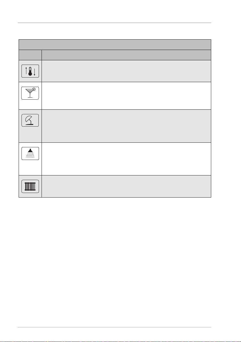
The following menu symbols appear in the top part of the display:
Here you can increase or reduce the room temperature. The supply line temperature
of the related heating circuit (5) will then be corrected by the value set here.
Here you can enter the number of hours for which the heating system will adopt or
remain in the "Manual day" operating mode. This applies only for the selected heating
circuit (5).
Here you can enter the number of days on which you will be absent. The heating
circuit will adopt the "Manual night" mode for the number of days selected here. Then
the heating circuit will return to the previously set operating mode. This applies only
for the selected heating circuit (5).
Here you can increase or reduce the temperature of the hot water. This applies for all
heating circuits.
Reducing the temperature can save energy when only little or no hot water is
required. Increasing the temperature is useful when you need more hot water.
Here you can change the heating circuit if more heating circuits are provided and
activated.
The "Comfort" menu can be set as the idle screen (standard screen) at:
• Program/Idle screen/Comfort menu.
MFC 1-6
This menu allows you to display and reset measurement values of the multi-function
controller. In this case the terminal designation precedes the designation for the sensor
(e.g. S1: Source). As in the "Solar circuit" menu item, you can also reset the minimum and
maximum values here.
Page 11
Displaying and changing the values in the menus
11
Menu item
Description
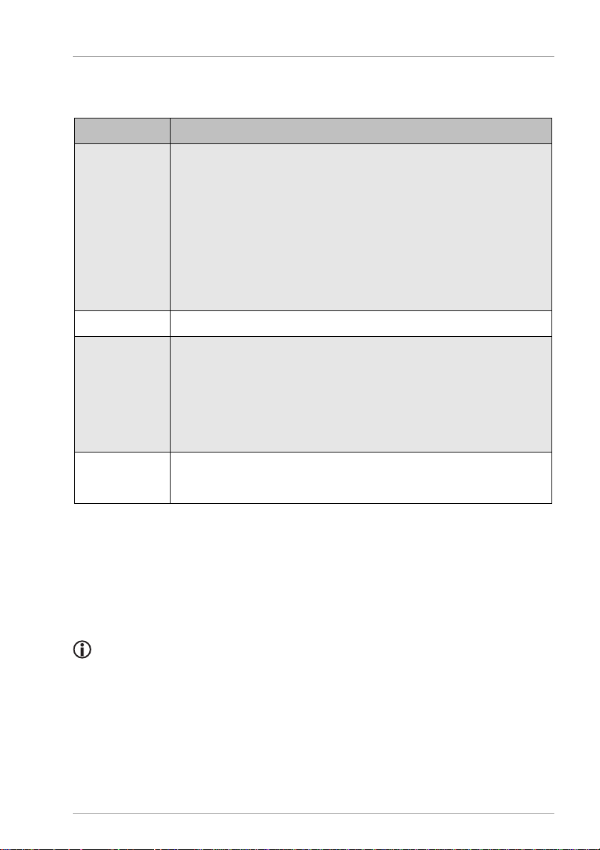
Solar The following status messages can be displayed:
– Fault
Flow Only if a flow fault occurs.
Heating circuit
The following status messages can be displayed:
– Chimney sweep
- time remaining.
MFC 1
–6
The following status messages can be displayed:
– Off
stems with two storage tanks, the tanks are denoted by the digits "1" and "2"
Status
This menu allows you to display the following status messages:
– Off
– Charging priority 1/2
– Collector protection
– System protection
– Recooling
– Anti-freeze
– Waiting time
– Tube collector
– Drain-back
– Parallel charging
– Off/Summer
– Day
– Night
– Party
– Holiday
– Eco mode active
– On
Efficiency
This menu allows you to display the following balance values and, if necessary, reset them:
• Operating hours (resetting is possible)
• Output (resetting is possible)
• Flow
For sy
respectively.
Page 12
Displaying and changing the values in the menus
12
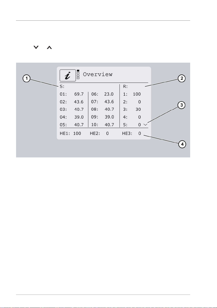
Overview
This menu allows you to display an overview of all outputs (2) and inputs (1). No value will
be displayed if a sensor is not connected. If an arrow symbol is shown (3), you can use the
buttons or to display the other values.
The HE outputs are displayed in the bottom part (4).
If flex 400 modules are connected, a menu item with an overview of the inputs and
outputs will appear for each of these modules.
Page 13
Displaying and changing the values in the menus
13
WARNING
ATT
ENTION
Menu item
Description
Storage tank 1/2
Storage tank max
Required maximum temperature
dTon Switch
-
on difference
dToff Switch
-off difference
Storage tank act
"Storage tank priority" function:
Activate or deactivate the storage tank with priority 2
Parallel charging
Temperature difference for the "Parallel charging" function
Speed control
Minim
um pump output with speed control
100% = Speed control off
Target temp
Required temperature for the "Target temperature" charging
method
Radiation
Value at which the "Tube collector" or "Drain
-
back" (radiation
-
controlled) functions start.
Tube start tim
e Time at which the "Tube collector" or "Drain
-
back" (time
-
controlled)
functions start
Tube stop time
Time at which the "Tube collector" or "Drain
-
back" (time
-
controlled)
functions stop
1.2 Displaying and changing values in the "Program"
menu
The "Program" menu allows you to display and change the parameters.
Risk of scalding from hot water as a result of incorrect settings.
Exercise particular care when configuring settings on the controller.
Take water samples after completion of the settings and check them
using a suitable thermometer.
Risk of system malfunctions due to incorrect settings.
Set parameters only if you know their effects.
Solar circuit
Specify the storage tank priority
Page 14
Displaying and changing the values in the menus
14
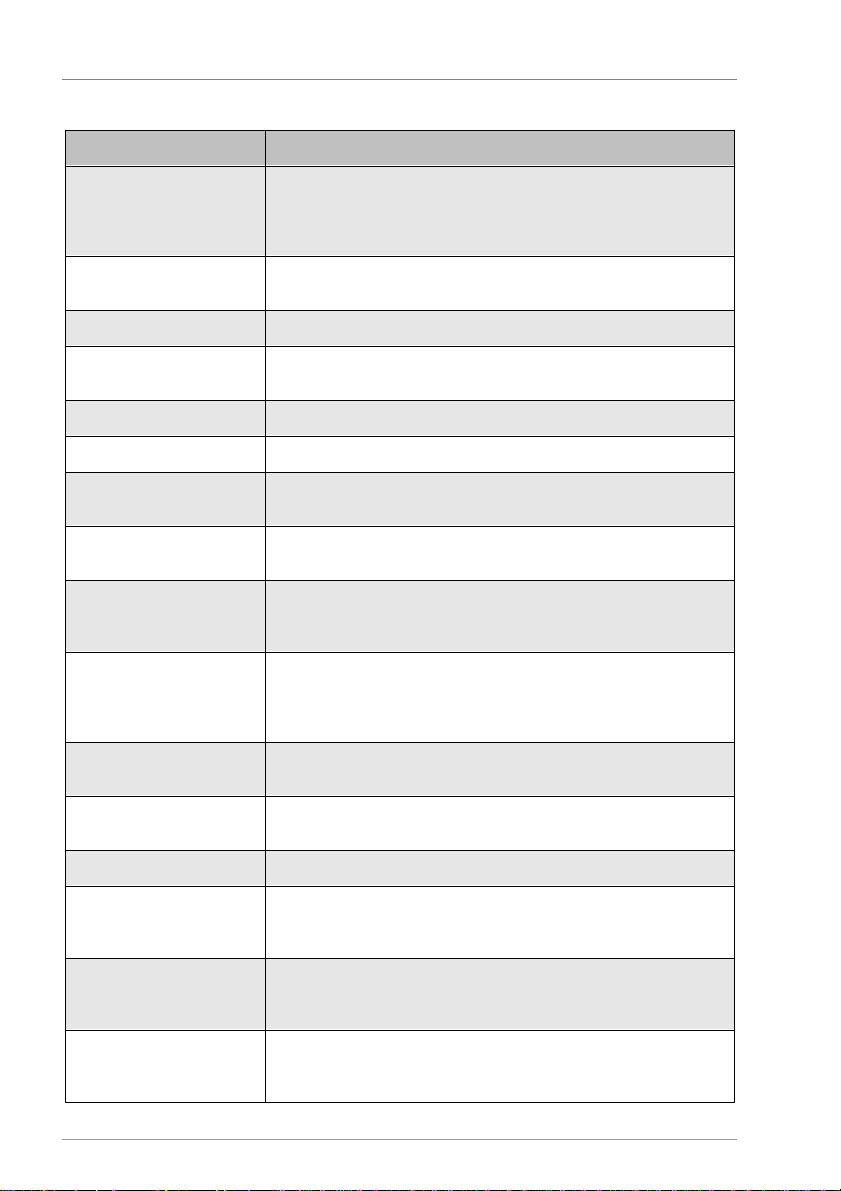
Menu item
Description
Description
Here you ca
n specify a designation for the heating circuit.
Ceiling heating system, Top floor, Flat, Building.
Number
You can also issue a
number. This makes sense when there are
several heating circuits e.g. on ground level.
Operating mode
Automatic
The control system runs by time program on the basis of the set
heating curves and in accordance with the outdoor temperature.
Manual day
The control system runs continuously in normal heating mode.
Manual night
The control system runs continuously in reduced mode.
Off
/Summer
The heating circuits are switched off. The mixers close and remain
in this position. The "Anti
-
freeze" function rema
ins active.
Party The heating circuit runs in "Manual day" mode for the duration of
the value set here.
Holiday
The heating circuit runs in "Manual night" mode up until the date
operati
ng mode when the selected date has elapsed.
Warmer
-
Colder/Room
The setpoint temperature for the supply line is changed by the
required room temperature directly her
e.
Correction 1
The setpoint temperature for the supply line is reduced or
increased by the value set here.
Correction 2
Second correction value for the supply line setpoint temperature.
Positive values will increase the setpoint temperature.
Week over
view Complete week overview of the set time window.
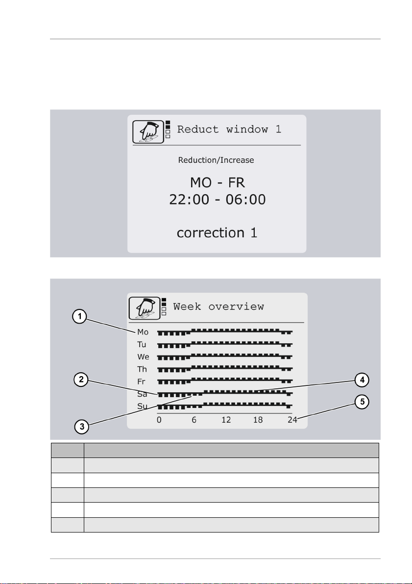
Reduction windows 1
–7
Here you can assign the 2 preset corrections and the "Off" mode to
circuit will run in automatic mode.
Mo–Fr Here you c
an select the week
-
days on which you want the
In this example the days selected are: Mo, Tu, We, Th, Fr.
22
:00–06
:00 Here you can select the start and stop times for the
reduction
In this example the times are
: Start:
22
:00, Stop:
06
:00
Heating circuit 1-4
The following terms are available: Heating circuit, Basement,
Ground level, Upper level, Floor, Radiator, Wall heating system,
selected here. The heating circuit will return to the previously set
set-point
value set here.
If a navo 400 room user terminal is connected, you can enter the
a specific time window. Outside the time window, the heating
programmed time window to be active.
windows.
Page 15
Displaying and changing the values in the menus
15
Pos. Description
1 Week days
2 Supply line correction 1, here: reducti
on of -10K
3 Supply line correction 2, here: reduction of
-5K
4 Normal heating mode (automatic mode) outside the time window
5 Day hours
Time window adjustment - heating system
For each time window you can select one of the preset SL corrections or "Off" mode. In
this way you can implement various reductions or increases as part of the day's program.
In the example below, the heating circuit will be operated with SL correction 1 from Mo to
Fr 22:00h. Outside the time window, the heating circuit will run in automatic mode.
Week overview
Page 16
Displaying and changing the values in the menus
16
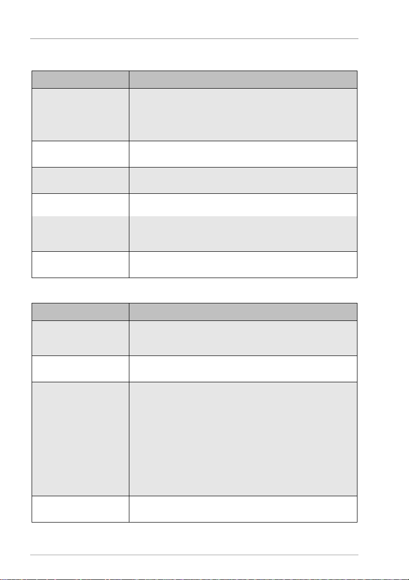
Menu item
Description
Function
Switching the "ECO mode" function on or off
be reduced by the respective lowering values.
Heating circuit lower
value
The request temperature for the heating circuit
is lowered by the
value set here.
HW lowering value
The request temperature for the hot water processing is lowered by
the value set here.
Time window 1
–3
Mo–Fr Here you can select the week
-
days on wh
ich you want the
In this example the days selected are: Mo, Tu, We, Th, Fr.
06:00-22:00 Here you can select the start and stop times for the time window.
In this example the times are: Start: 06:00, Stop: 22:00
Menu item
Description
Start setpoint value
If the process water temperature drops below the value set here,
request will be switched on.
Stop setpoint value
If the process water te
mperature rises above the value set here, the
hot water processing function will be switched off.
Priority
Here you can define the response of the heating circuits during the
setpoint temperature for the hot water
processing is reached.
Charging time
(alternating mode)
Here you can define for how long the hot water processing has
priority during alternating mode.
ECO mode
This function can be switched on or off for each heating circuit and
for the hot water request.
Within the time window, the request values for the reheating will
Outside the time window the function is not active.
programmed time window to be active.
Hot water
the hot water processing function will become active and the boiler
hot water processing.
Off: The heating circuits will continue to run during the hot water
processing.
On: When the hot water processing is active, the heating circuits
will be switched off and the mixers will be closed.
Alternate: When the hot water processing is active, the storage
tank will be given charging priority during the set "Charging time".
When the charging time comes to an end, the hot water processing
will be switched off for the "Waiting time" and the heating circuits
will be activated again. This alternation will contine until the
Page 17
17
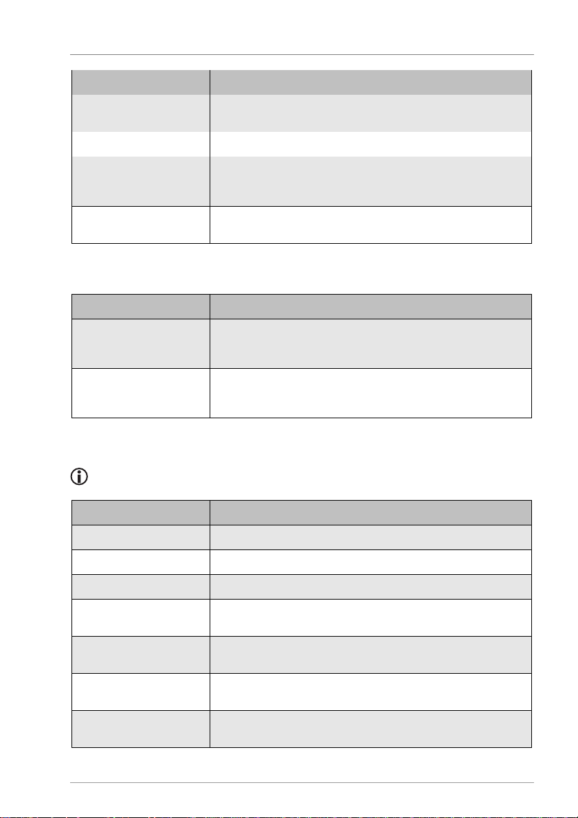
Menu item
Description
Waiting time (alternating
mode)
Here you can define for how long the hot water processing must
remain
in waiting mode.
Time window 1
–3
Mo–Fr Here you can select the week
-
days on which you want the
In this example the days selected are: Mo, Tu, We, Th, Fr.
06:00–22:00 Here you can select the start and stop times for
the time window.
In this example the times are: Start: 06:00, Stop: 22:00
Menu item
Description
Function
Switch the "Chimney sweep" function on or off
be activated. The m
ixers move to position "Open".
Runtime
Here you can set the runtime for the "Chimney sweep" function.
the previously selected operating mode.
Menu item
Description
Target temp
Switch
-
on temperature
Hysteresis
Temperature range
Waiting time
Duration of waiting time for the "Cascade" function
Tmax sink
Maximum temperature of the sink for the "Temperature
difference
controller"
and “Wood
-
fired boiler” functions
Diff. controller max
Switch
-
on difference for the "Temperature difference controller"
function
Tmin source
Minimum temperature of the source for the "Temperature
difference controller" and “Wood
-
fired boiler” functions
Diff. controller min
Switch
-
off difference for the "Temperature
difference controller"
function
Chimney sweep
MFC 1-6
Displaying and changing the values in the menus
programmed time window to be active.
The night heating mode will be started and the heating pumps will
When this time has elapsed, the system will switch automatically to
Different menu points can be displayed in this menu depending on the functions
selected for the multi-function controller.
Page 18
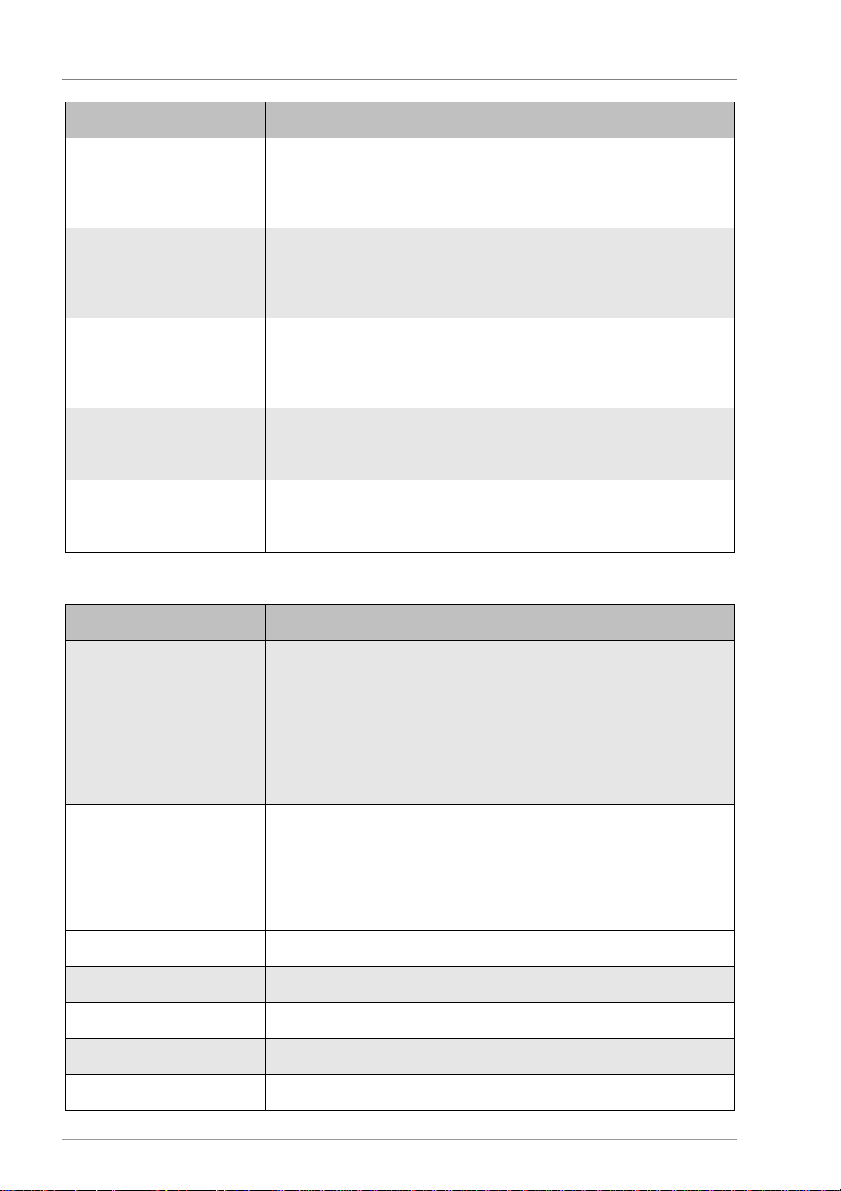
Displaying and changing the values in the menus
18
Menu item
Description
Tlimit min.
Lower limit of a temperature range
range.
Tlimit max.
Upper limit of a temperature range
range.
Date Here you can enter the perio
d (start date and end date) in which
the start date, the end date will be set in the following year.
Time 1
–
3: Start
Start time for time wi
ndows 1
-3:
specify the start times for time windows 2 and 3.
Time 1
–
3: Stop
Stop time for time windows 1
-3.
specify the sto
p times for time windows 2 and 3.
Menu item
Description
Idle screen
SD card on/off
Deactivate microSD card.
progress.
Warning signal
Switch the acoustic warning signal on or off when there are faults
Time Current time
Date Current
date
Summer time
Automatic changeover between summer time and winter time
Firmware
Display of the current firmware version
With this value you can set the lower limit of a temperature range.
The multi-function controller switches only within this temperature
With this value you can set the upper limit of a temperature range.
The multi-function controller switches only within this temperature
you want the multi-function controller be active.
The year is not entered. If you enter an end date which precedes
When the start time for time window 1 has been specified, you can
When the stop time for time window 1 has been specified, you can
System
Here you can define to which display the controller will switch if no
button is pressed for one minute.
Heating circuit: An overview of the measured values in the heating
circuit
Solar circuit: An overview of the measured values in the solar
circuit
Comfort menu: In the "Comfort" menu you can enter changes
This menu item will be displayed only if a microSD card has been
inserted.
When it is inserted, the microSD card is automatically activated. An
SD card symbol in the "Info" menu indicates that data logging is in
Page 19
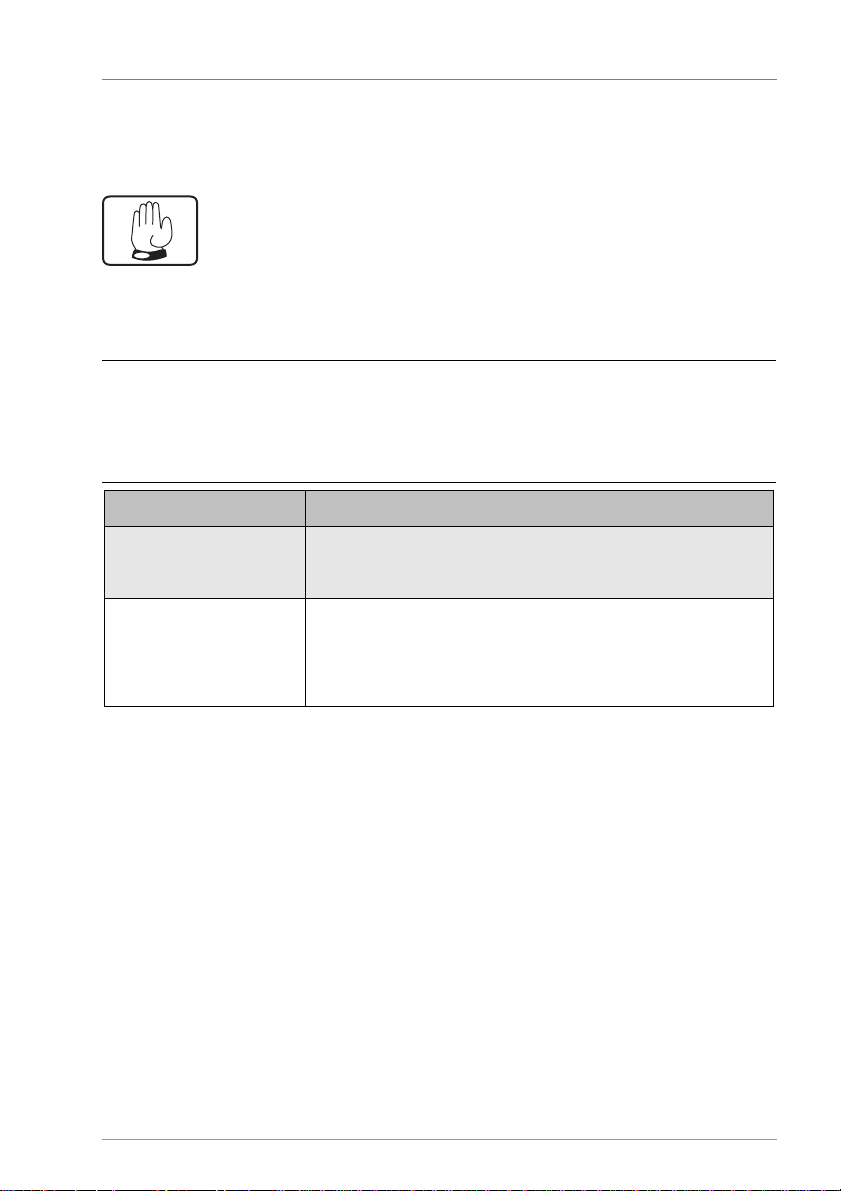
Displaying and changing the values in the menus
19
ATTENTION
Menu item
Description
Output R0
–R7, HE1-HE3 Switch switching output R0
–R7, HE1-HE3 on o
r off manually.
switching outputs in use will be displayed.
Delayed off
When the menu is closed, the controller will switch to automatic
pump symbol.
1.3 Controlling switching outputs in the "Manual mode"
menu
The "Manual mode" menu allows the controller's switching outputs to be turned on and
off for test purposes. To enable the controller to run in automatic mode again, you have to
exit manual mode after completion of setting tasks.
Risk of system malfunctions due to incorrect settings.
Make sure that only specialist personnel ever make any changes to the
values in this menu.
Depending on the hydraulic layout which has been set, only the
mode after the delayed off has elapsed.
All outputs in manual mode remain active during the delayed off
period. In the "Info" menu, a hand symbol appears instead of the
Page 20
Displaying and changing the values in the menus
20
ATTENTION
1.4 Displaying and changing values in the "Basic
settings" menu
The "Basic settings" menu allows you to display and change basic settings.
Risk of system malfunctions due to incorrect settings.
Make sure that users use only user mode.
Make sure that the values are only ever changed by specialist
personnel.
There are two operating modes:
• User mode
• Editing mode
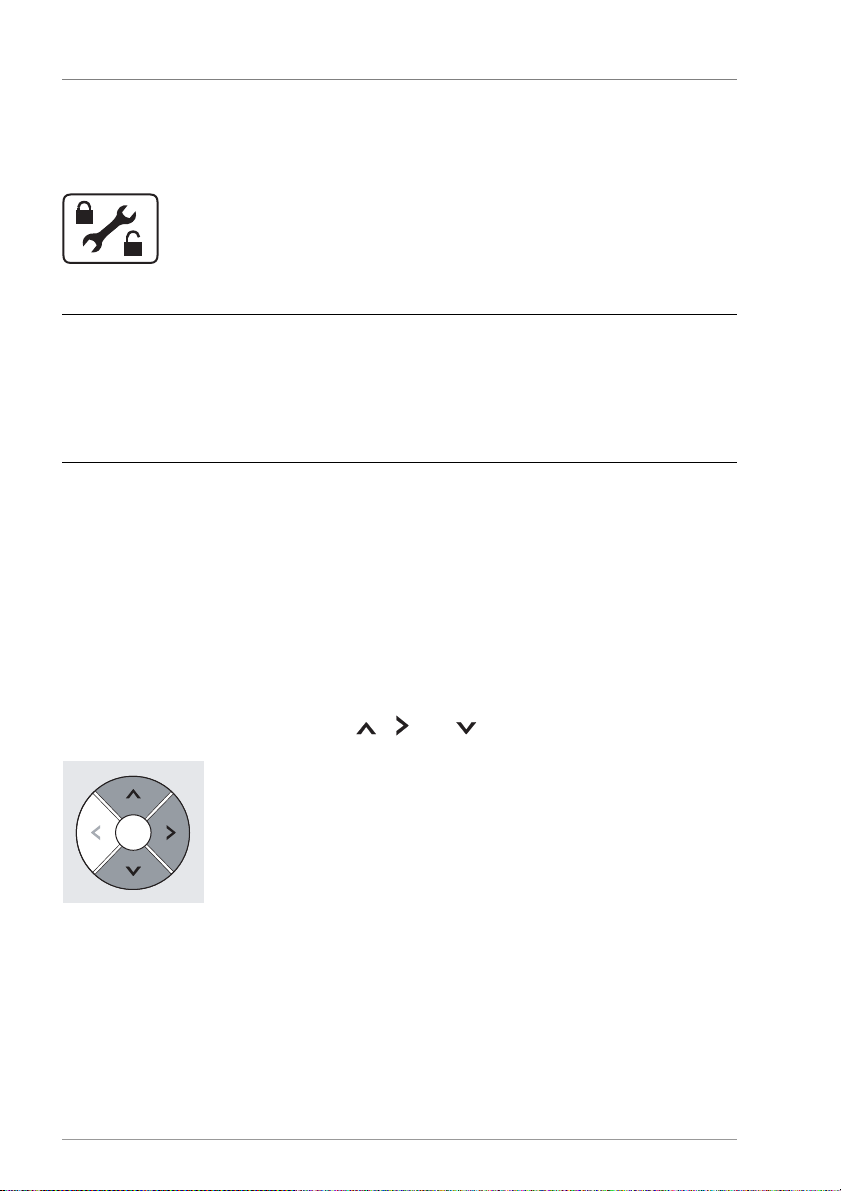
In user mode you can display values in this menu, but you cannot make any changes to
them. If user mode is activated, the menu symbol is displayed in the form of a "locked"
symbol.
In editing mode you can display and make changes to values in this menu. If editing mode
is activated, the menu symbol is displayed in the form of an "unlocked" symbol. Only
specialist personnel are permitted to activate editing mode.
To activate editing mode, press the , and buttons simultaneously.
The menu symbol will be displayed in the form of an "unlocked" symbol. Editing mode will
be active.
Page 21
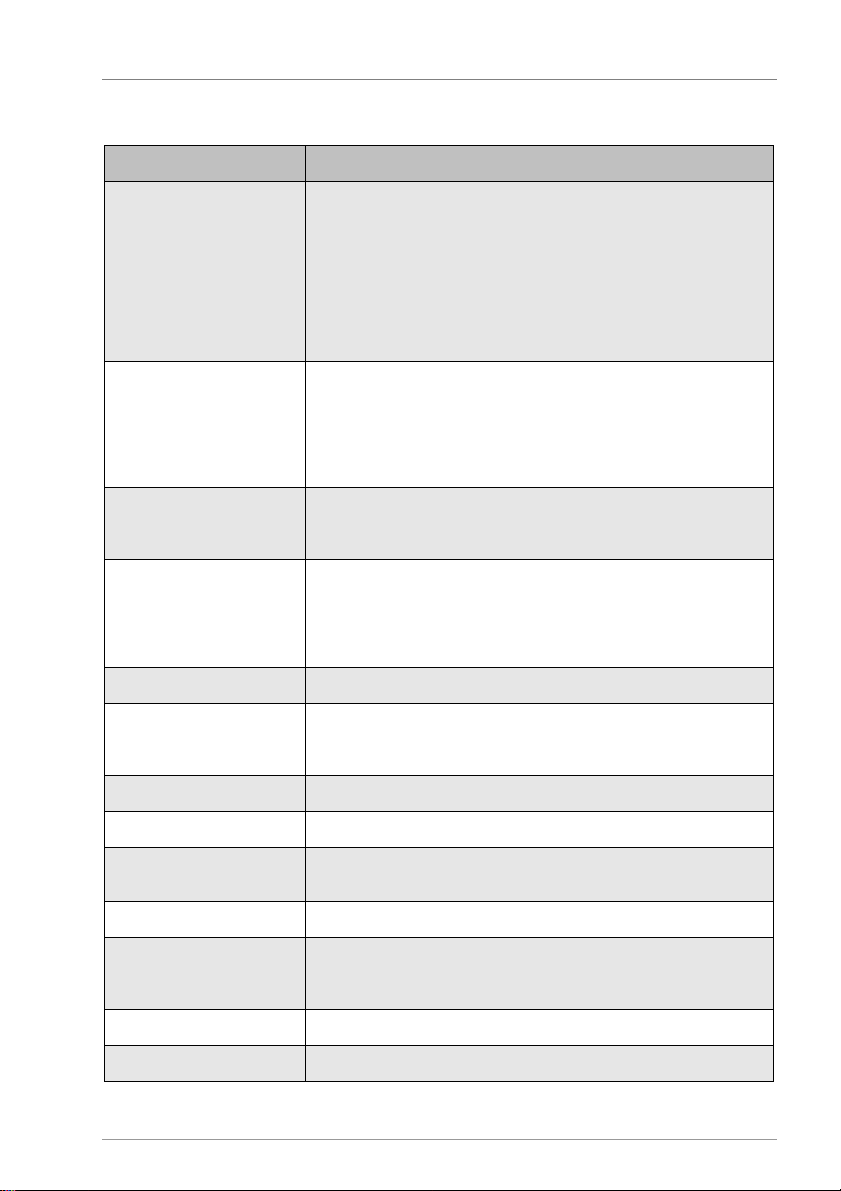
21
Menu item
Description
Hydraulic layout
Set the system type.
and additional functions will be reset.
Speed
With these parameters you can influence the speed control.
Please
change
the preset
values
only if necessary.
Charging break
"Storage tank priority" function: Brea
k between charging the
Multi-tank systems only
Priority
"Storage tank priority" function: Order in which
storage tank 1 and
b
: Storage tank 2
Parallel cha
rging Switch the "Parallel charging" function on or off
Charging method
You can choose between the following charging methods:
– Target temperature.
Collector prot
Function
Switch the "Collector protection" function on
or off
Temperature
Temperature at which the "Collector protection" function becomes
active
Drain-back (Only if collector protection is off)
Function
Switch on the "Drain
-
back" function in the required control type
Switch off the "Drain
-
back" function.
Fill time
Fill time for the "Drain
-
back" function
Min runtime
This parameter is used to set a minimum pump runtime.
Solar circuit
Displaying and changing the values in the menus
Layout: abc.x
a: Number of storage tanks
b: Number of collectors
c: Extensions
(0=None, 1=Heat exchanger, 2=Bypass)
x: Variant
When the hydraulic layout is changed, all the preset parameters
P Prim: P (proportional) component gain, pump output in % per
Kelvin.
I-Time Prim: Time factor for correction by the I (integral action)
component in seconds.
storage tanks
storage tank 2 are charged. Only for multi-tank systems.
Layout: ab
a: Storage tank 1
– deltaT (temperature difference)
(temperature difference/radiation-controlled).
Page 22
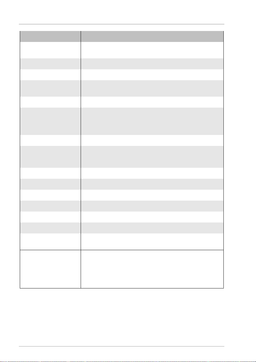
Displaying and changing the values in the menus
22
Menu item
Description
Condition time
This parameter is used to set how long the conditions for switching
on an
d off must be active in order to take effect.
Recooling
Function
Switch the "Recooling" function on or off
Recooling temp
The temperature to which the storage tank is recooled after the
"Collector protection" function was active
Tube collector
Funct
ion Switch on the "Tube collector" function in the required control type
Switch off the "Tube collector" function.
Pump runtime
Pump runtime of the "Tube collector" function
Interva
l Interval time between the pump runtimes
Time Interval period for control via temperature change
deltaT
Temperature for control via temperature change
Anti-freeze
Function
Switch the "Anti
-
freeze" function on or off
Sensor
Select the sensor input
T
emperature
Temperature at which the "Anti
-
freeze" function becomes active
System protection
Temperature
Temperature at which the "System protection" function becomes
active
Pump type R1/R2/R3
You can choose between the following pump types at the R1/R2
/R3
– PWM inverted.
(time-controlled/control via temperature change/radiationcontrolled).
switching output:
– 230 V block modulation
– Analog (R1 and R2 only)
– PWM
Page 23
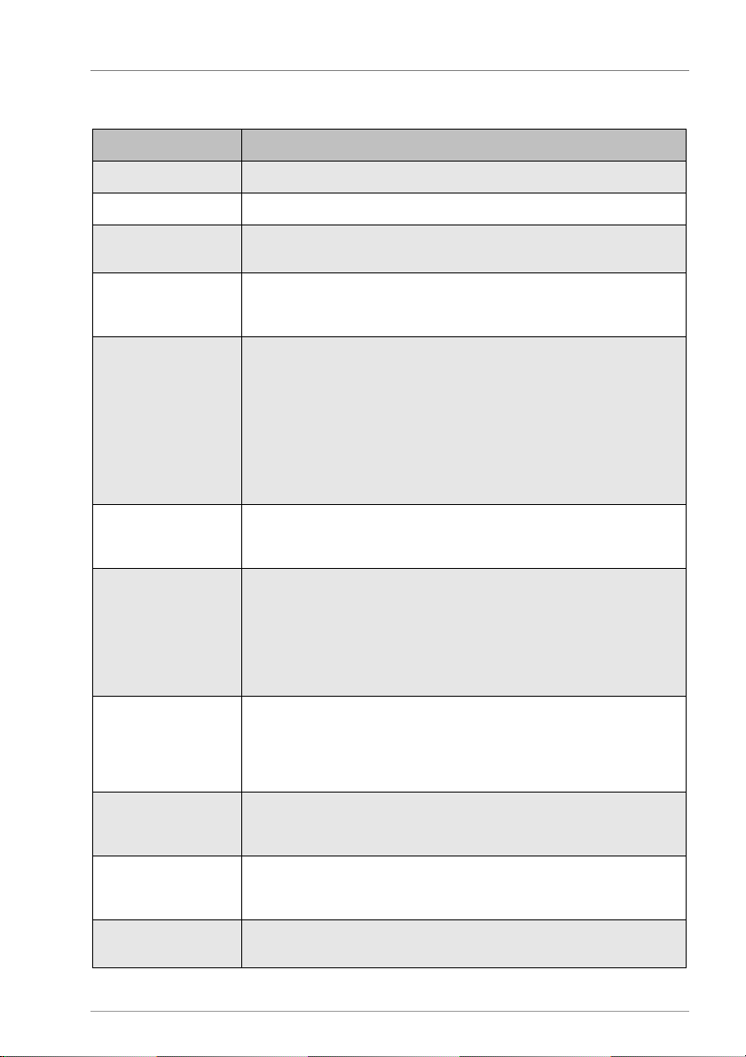
23
Menu item
Description
Heating circuits 1
-4*
For more settings for the individual heating circuits, see below this table.
Heating curve
Lin
ear The heating circuit control of the two heating circuits is based on a linear
calculation.
Curve set
The heating circuit control of the two heating circuits is based on a
curve fr
om a set of curves
starting on page
29.
Multi-room control
If you use more than one room sensor, you can implement multi
-
room
Room influence
Here you can define the influencing factor of the room sensors.
temperature correction will be calculated accordingly.
OT smoothing
Here you can set a value in hours for the smoothing of the outdoor
type 70, 55, 40): 24h
dt On heat
If the temperature at the middle of
the storage tank lies below the
be considered.
dt Off heat
If the temperatu
re at the middle of the storage tank lies above the
the reheating will be switched off.
Request
Switch the "Request" function on or off
function controller will become available on R0.
Min runtime
This parameter is used to set a minimum time during which the request
will remain active.
Heating circuit
Displaying and changing the values in the menus
heating curve. Details can be found in the section Selecting the heating
control with this function. Comfort will be increased and energy
consumption will be optimised.
You can choose between the following room analysis methods:
- Min: The lowest temperature of all active sensors is decisive
- Max: The highest temperature of all active sensors is decisive
- Average: The average temperature of all active sensors is decisive
- Switch: The heating circuit will be switched off when the room
setpoint temperature is exceeded at all active sensors
You can chooce between low, medium and high and the supply line
tempertaure according to the building's insulation. This makes
allowance for the building's inertia.
Examples:
Poorly insulated building (e.g. an old building with no insulation): 4h. A
very well insulated building (e.g. a new building, a KfW efficiency house
calculated supply line setpoint value plus "dt On heat", the reheating by
boiler will be switched on.
If there are two heating circuits, the higher supply line setpoint value will
calculated supply line setpoint value plus "dt On heat" plus "dt Off heat",
Here you can deactivate the boiler function. In this case the multi-
Page 24
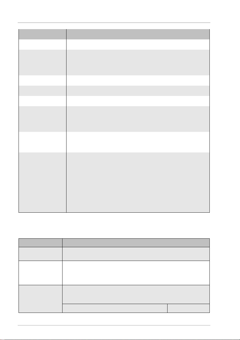
Displaying and changing the values in the menus
24
Menu item
Description
Delayed off
The request remains active during the delayed off period.
Reheat
sensor 2
Sensor for switching off the burner request. This sensor is freely
function automatically uses the "Middle of storage tank" sensor.
Hot water
Function
Switch the "
Hot water" function on or off
Sensor ST top
Select the sensor input for the storage tank top
HW switch
-
off sensor
Sensor for switching off the burner request. This sensor is freely
function automatically uses the "Top of storage tank" sensor.
Anti-freeze
This function is active at all times. If the outdoor temperature drops
happens irrespective of the
selected operating mode.
Screed heating
Switching the "Screed heating" function on or off.
Menu item
Description
Heating circuit
- Unmixed:
The "Unmixed heating circuit" is switched on
Mixed:
The "Mixed heating circuit" is switched on
Assignment
The outputs and the sensors of every heat
ing circuit can be assigned
Flex 1 / 2 / 3 / 4: HCs in the flex
-
modules 1, 2, 3 or 4
Heating curve 1
-4
Here you can set either the linear heating curve or the h
eating curve
curve" menu point. You can set the following parameters:
Linear
Curve set
assignable.
A message will appear if the sensor is not connected. The reheating
assignable.
A message will appear if the sensor is not connected. The reheating
below the threshold set here, the heating circuits will be activated. This
Here you can start a defined program for heating and cooling the screed.
You can choose between the following modes:
- Auto: Screed heating in automatic mode
- Hold: Holding the maximum value for the set "Duration max value"
- Cool down: Cooling down according to profile, beginning with the 1st
cool down step
Do not start the program until all the parameters have been set.
Subsequent parameter changes will not take effect until the
function is restarted.
* Heating circuits 1-4
-
internal or to the external flex-modules.
Internal 1 / 2: the integrated HCs of the controller
selected from the set of curves, depending on the setting for the "Heating
Page 25
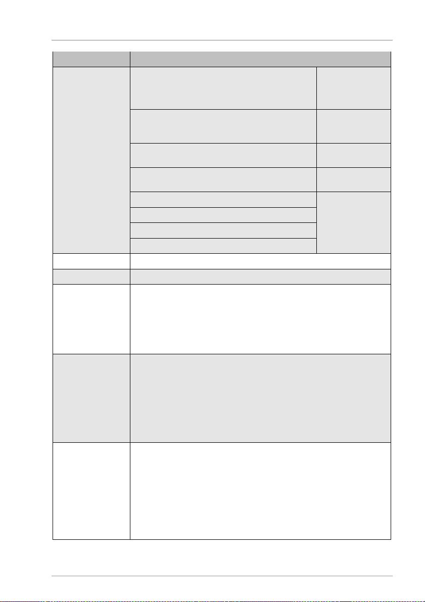
Displaying and changing the values in the menus
25
Menu item
Description
Switch
-
off day
off.)
Switch
-
off day
Switch
-
off night
above this value, the heating will be switched off.)
Switch
-
off night
Supply line max limit
(Maximum supply line temperature)
Supply
line max
limit
Supply line min limit
(Minimum supply line temperature)
Supply line min
limit
Outdoor temp max
Steepness
Outdoor temp min
Supply line temp max
Supply line temp min
Mixer 1
-4
Mixer type
Mixer with 230V or analog actuation
Se
ttings for mixer
Total actuating time:
Time taken by the mixer from the position "Open"
actuated.
Settings for mixer
P component:
Influences how strongly the mixer reacts to
a deviation
Heating circuit assignment "Internal 2": HE1
Room sensor 1
-3
Here you can activate up to three room user terminals, room sensors or
input to which they are connected.
(If the average outdoor temperature during the day
lies above this value, the heating will be switched
(If the average outdoor temperature in the night lies
with 230V actuation
with analog
actuation
to the position "Closed".
Actuating time: Here you can set how long the mixer is actuated when
the heating circuit actual value deviates from the supply line setpoint
value. The deviation is entered in seconds per Kelvin.
Cycle time: Here you can enter the time interval in which the mixer is
from the supply line setpoint value.
I component: Influences how strongly the mixer reacts to a lasting
deviation from the supply line setpoint value.
Cycle time: Here you can enter the time interval in which the mixer is
actuated.
Output assignment:
Heating circuit assignment "Internal 1": HE2
room actuators.
You can choose between the following types:
- navo 400: Room user terminals with room temperature sensor. Is
possible and recommended only as room sensor 1.
- Room sensor: Commercially available room sensor with PT1000 sensor
- Room actuator: Commercially available room actuator with potential-
free output
For room sensors and room actuators you must assign another sensor
Page 26
Displaying and changing the values in the menus
26
Menu item
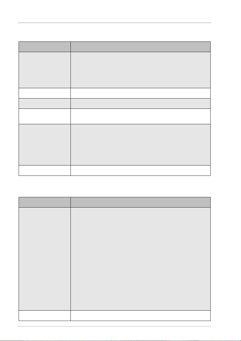
Description
Measurement method
Activate yield measurement with the preferred measurement method.
circuit)
Pulse value
Pulse value for the "DFG" measurement method
VFS type
Select type for the "VFS" measurement
method.
DFA Flow rate for the "DFA" measurement method.
Unit: Litres per minute
Glycol type
You can choose between the following glycol types for the coolant:
– none (if you use on
ly water)
Glycol percentage
Mixing ratio for the coolant
Menu item
Description
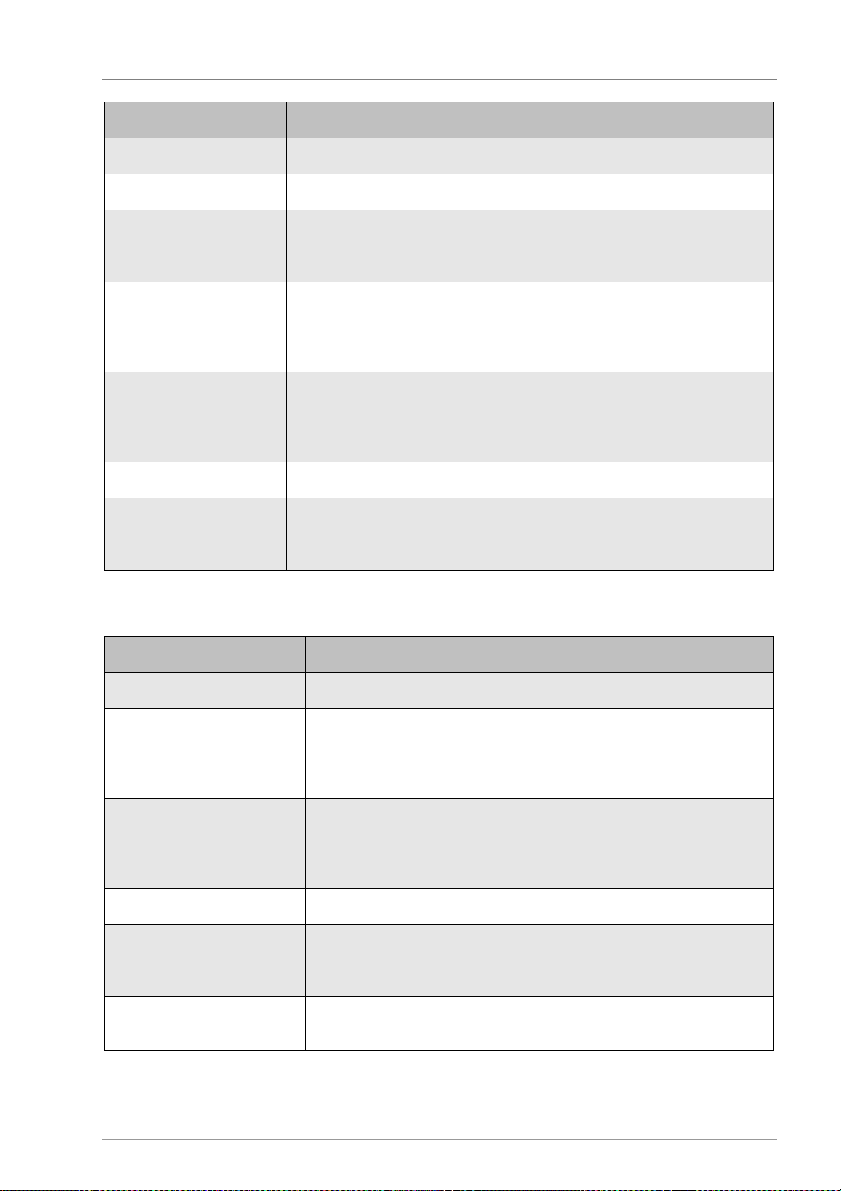
Function
Here you can switch on the MFC in the following functions:
– Storage tank cooling (only MFC 3).
Source sensor
Select the sensor input for the s
ource
Yield measurement
You can choose between the following measurement methods:
– DFG (flow sensor)
– VFS (vortex flow sensor)
– DFA (flow indicator –only for yield measurement 1 in the solar
– Anro
– Ilexan EG/E/P
– Antifrogen L/N
– Tyfocor L5.5
– Dowcal 10/20/N.
MFC 1-6
– Cooling
– Heating
– Difference controller
– Threshold value
– Return line boost
– Wood-fired boiler
– Circulation temp.
– Circulation time
– Alarm
– Timer
– HW reheating
– Temperature range
– Modulation
– Cascade
– Yield
– Mixer (only MFC 1)
– Valve (only MFC 2)
Page 27
27
Menu item
Description
Sink sensor
Select the sensor input for the sink
Output
Select the output of the MFC
Speed
"Wood
-
fired boiler", “Return line boost” and “Wood
-
fired boiler”
100% = Speed control off
Delayed off
The switching output remains active during the delayed off period.
The delayed off is active irrespective of all trip conditions.
Runtime
Duration of runtime for following functions:
– "Solar redundancy".
Waiting time
Duration of waiting time for the "Time
-
controlled circulation" function
Link Logical link from the output to the other outputs with AND/OR logic.
page 29.
Menu item
Description
Load language
Change the language
Parameter
Backup parameters from controller to microSD card.
inserted.
Generate record
The current settings and parameters will be saved in a text file to
inserted.
Factory settings
Load factory settings
Firmware update
Carry out a firmware update.
inserted. Only the firmware files will be displayed.
Number Flex I/O
If additional flex modules are connected, the number must be
stated here.
System
Displaying and changing the values in the menus
functions: Minimum pump output with speed control.
You can set the delayed off period here.
The setting range is 0–600 sec.
– "Time-controlled circulation"
– "Solar boost"
Details can be found in the section Setting the logical link starting on
Load parameters from microSD card to the controller.
This menu item will be displayed only if a microSD card has been
the microSD card.
This menu item will be displayed only if a microSD card has been
This menu item will be displayed only if a microSD card has been
Page 28
"Heating circuit" function
28
2 "Heating circuit" function
The device can be used to control up to two heating circuits on the basis of the outdoor
temperature. These circuits can be mixed or unmixed. You can define separate control
characteristics for each heating circuit.
2.1 Mixed heating circuit
The control characteristics described in the following can be configured only in
the "Basic settings" menu.
With this function, the control system adjusts to the setpoint temperature for the supply
line by actuating the heating circuit pump and the heating circuit mixer according to the
outdoor temperature development.
You can choose between two settings:
• Linear heating curve
• Heating curve from a set of curves.
Defining the linear heating curve
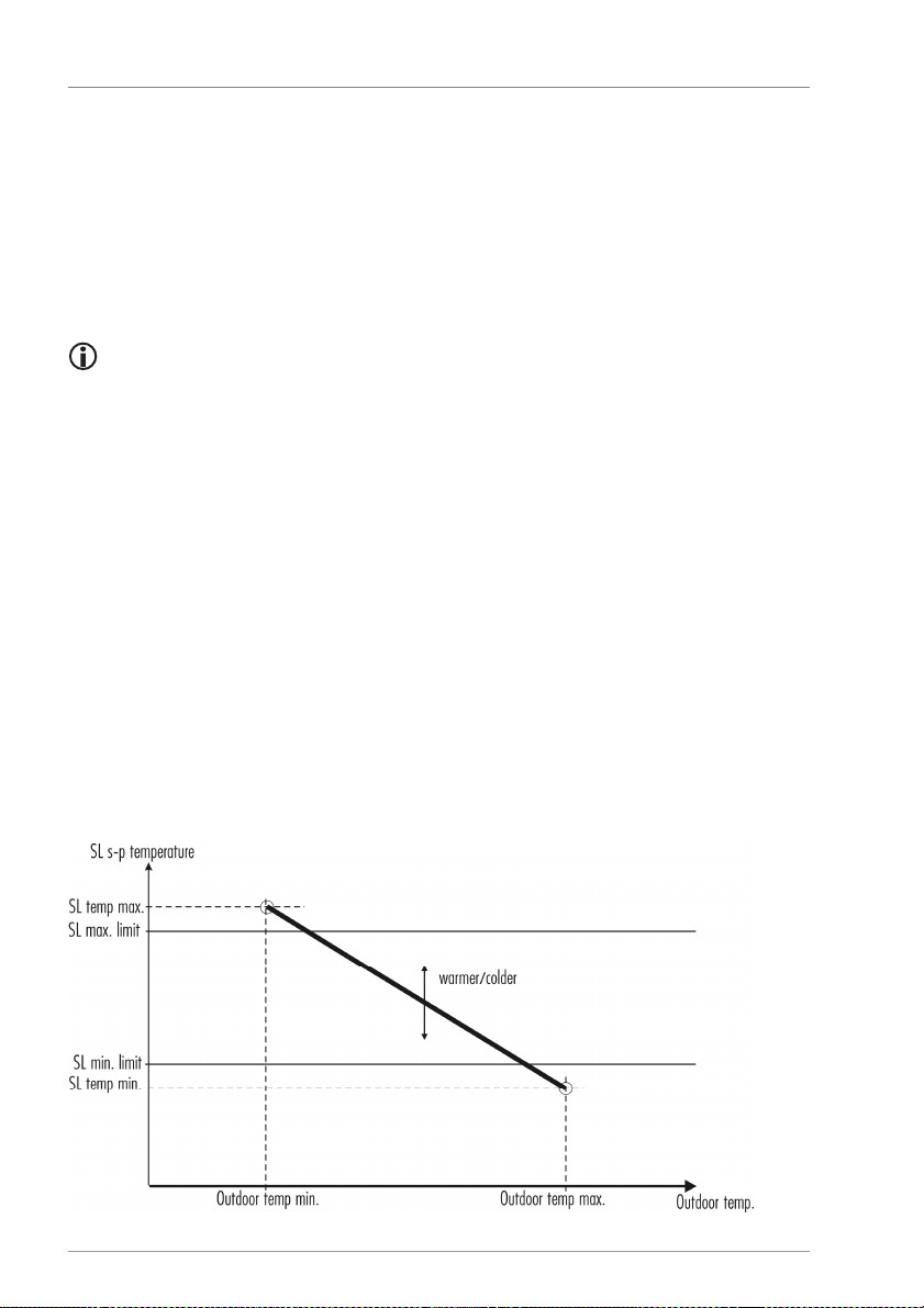
The heating curve (thick line) is defined by two vertexes. The first or upper vertex is
formed from the parameters "Supply line temperature max" and "Outdoor temperature
min". The second or lower vertex is formed from the parameters "Supply line temperature
min" and "Outdoor temperature max". The parameters "Supply line max limit" and "Supply
line min limit" are used as absolute limits for the supply line setpoint temperatures of the
upper and lower heating circuits. You can use the parameters "Switch-off day" and
"Switch-off night" to define the outdoor temperature at which the heating circuits are
switched off if exceeded.
Page 29
"Heating circuit" function
29
control and mixer control.
Selecting the heating curve from a set of curves
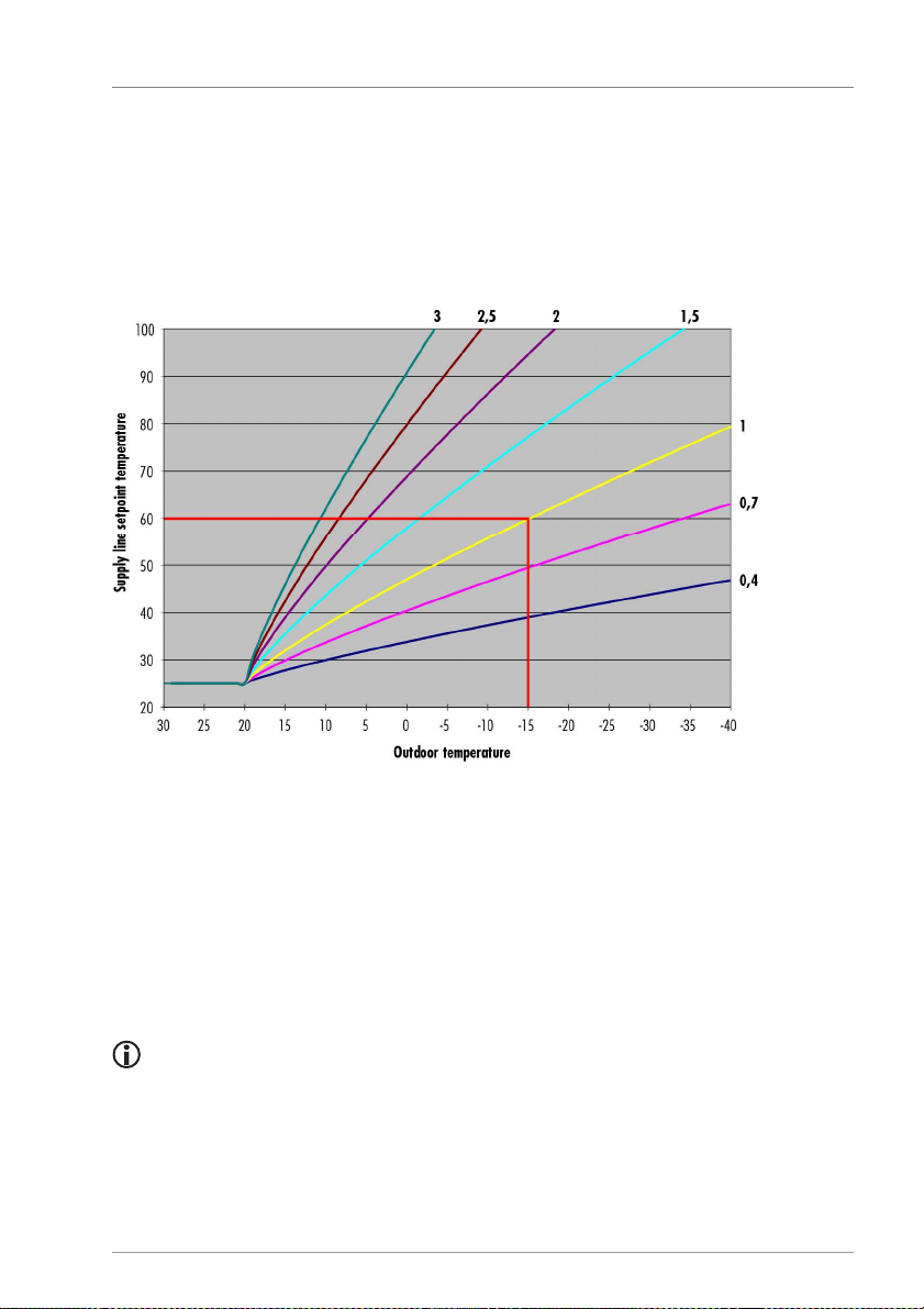
Assuming a desired room temperature of 20 °C, a corresponding supply line setpoint
temperature is derived from the selected heating curve and the outdoor temperature
development. The parameters "Supply line max limit" and "Supply line min limit" are used
as absolute limits for the supply line setpoint temperatures of the upper and lower
heating circuits. You can use the parameters "Switch-off day" and "Switch-off night" to
define the outdoor temperature at which the heating circuits are switched off if exceeded.
The example graphic shows that when curve 1 (yellow) is selected and the outdoor
temperature is -15 °C, the supply line setpoint temperature will be 60 °C.
2.2 Unmixed heating circuit
The heat source of the heating circuit (middle of storage tank) will be adjusted to the
corresponding supply line setpoint temperature on the basis of the configured settings
(linear heating curve/selection from a set of curves) according to the development of the
outdoor temperature.
When the heating circuit pump is activated, the requested temperature of the
heat source (middle of storage tank) goes directly into the heating circuit without
In the "Program" menu you can use the parameters "Warmer-Colder" and "Reduction
temperature" to manually influence the supply line setpoint temperatures of the heating
circuits. The "Warmer-Colder" parameter produces a general increase or reduction of the
supply line setpoint temperature. The "Reduction temperature" indicates by how many
Page 30

"Heating circuit" function
30
Kelvin the supply line setpoint temperature will be lowered in reduction mode, i.e. outside
the active time windows.
2.3 Switching the heating circuit pumps off and on
Heating circuit pumps are switched off in the following cases:
• The value set for "Switch-off day" in the operating modes "Automatic" or "Manual day"
for the respective heating circuit is exceeded.
• The value set for "Switch-off night" in the reduction mode for the respective heating
circuit is exceeded.
• The value set for "Supply line max limit" plus 5 K control bandwidth is exceeded (only
in the mixed heating circuit).
• The "HW priority" function is switched on and the "HW reheating" function is active.
Heating circuit pumps are switched on again in the following cases:
• The outdoor temperature drops below the outdoor temperature set in the respective
operating mode of the heating circuit by more than 1 K.
• The supply line temperature drops below the set supply line limit temperature by more
than 1 K.
• The "HW reheating" function is no longer active.
2.4 Hot water
If the temperature at the top of the storage tank lies below the value set for "Start setpoint
value", the reheating by boiler will be switched on.
If the temperature at the top of the storage tank lies above the value set for "Stop setpoint
value", the reheating by boiler will be switched off.
If the "HW priority" function is switched on, the heating circuit pumps will be switched off
and the mixers will be closed during the HW reheating.
You can also switch on the "HW reheating" function by MFC. This MFC switches in parallel
to the "Hot water" function and has no further parameters.
Page 31
"Heating circuit" function
31
the selected solar functions.
When you switch off the heating circuit (e.g.
via the "Program/Operati
ng
changes to take effect.
2.5 Putting the heating circuits into operation
More or fewer heating circuit functions are available depending on the scope of
The putting into operation of the heating circuit 1 as a mixed heating circuit will be
described by way of example.
Select the "Basic settings" menu.
Select the "Heating circuit" menu point.
Select the "Heating circuit 1" menu point.
Select the "Mixed" menu point.
The OK symbol will be displayed and will flash.
To confirm the entry, select .
The value "Mixed" will be indicated for the "Heating circuit 1" menu point.
The heating circuit is thus activated as a mixed heating circuit. All related switching
outputs and sensor inputs are now assigned and will be actuated or evaluated
accordingly by the controller. Further details can be found in the document Hydraulic
layouts.
mode" menu point), the supply line setpoint value will be set to 11 °C. When
you switch on the heating circuit again, the supply line setpoint value will be reset
without delay to the regular working value.
2.6 Screed heating
You can activate the function when all the relevant parameters have been set.
If you change any parameters subsequently, you must restart the function for the
Here you can start a defined program for heating and cooling the screed.
You can choose between all mixed heating circuits.
All other heating circuit functions are deactivated during screed heating.
When the heating and cooling down have ended, the control system will be reset to the
previously selected mode. If there is a power failure, the function will be maintained and
will continue from the point of disconnection.
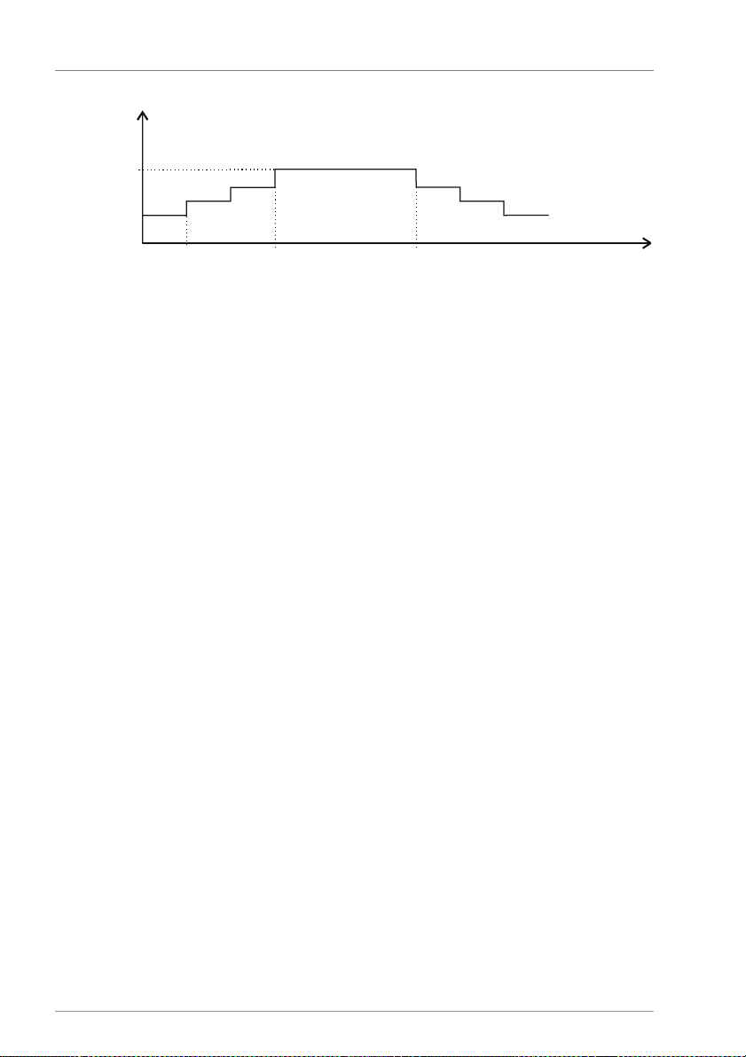
A step pattern is defined using a start temperature and maximum temperature, step
duration and increment, and holding duration of the maximum value.
Page 32
"Heating circuit" function
32
Max. temp.
Duration Holding
t
°C
Start temp.
The number of steps is calculated from the difference between the start temperature and
the maximum temperature and from the increment.
2.7 Room sensor (RS)
You can connect up to 3 room sensors per heating circuit. The navo 400 room user
terminal, which acts as both a room sensor and remote control, can be connected
respectively as room sensor 1 via the bus.
Otherwise you can connect commercially available room sensors with PT 1000 and room
actuators with potential-free output in any order and combination.
In this way you can create multi-room controllers for greater comfort and a more efficient
energy consumption.
Page 33

“Solar” function
33
3 “Solar” function
Setting the general controller functions
The general controller functions allow you to configure the settings for charging the
storage tanks. You can set the following controller functions:
• Charging method
• "Storage tank priority" function
• "Parallel charging" function
• Pump control
• "Tube collector" function
3.1 Setting the charging method
In order to optimise the energy output, you can choose from the following charging
principles:
• "Temperature difference" charging principle
• "Target temperature" charging principle
The charging principle is selected in the following menu item:
• Basic settings/Solar circuit/Charging principle
"Temperature difference" charging method
In the case of the "Temperature difference" charging principle, the solar circuit pump is
controlled in such a way that the temperature difference between the collector and the
storage tank is maintained at as constant a level as possible.
"Target temperature" charging method
In the case of the "Target temperature" charging principle, the solar circuit pump is
switched on when a certain specific target temperature has been reached in the collector.
For this function you can set the following parameters:
• Program/Solar circuit/Target temperature
3.2 Setting the "Storage tank priority" function
This function is available only for 2 or more storage tank systems.
Page 34
“Solar” function
34
pump two
-
way valves. 2 storage tanks are charged
in parallel.
The "Storage tank priority" function controls the tank charging of dual tank systems. There
are the following types of dual tank systems:
• Systems with two separate storage tanks
• Systems with a stratified storage tank (a storage tank with two heat exchangers, one on
top of the other)
• Systems with a storage tank in combination with a swimming pool
• etc.
In control mode, the first storage tank is charged as a storage tank with priority 1. If more
heat is generated than required, the excess energy is fed into the second storage tank
(storage tank with priority 2). In the case of the stratified storage tank, the top heat
exchanger is defined as the first storage tank.
For this function you can set the following parameters:
• Basic settings/Solar circuit/Hydraulic layout
• Basic settings/Solar circuit/Charging break
• Basic settings/Solar circuit/Priority
• Program/Solar circuit/Storage tank active
3.3 Setting the "Parallel charging" function
This function is available only for 2 or more storage tank systems with pumps or
This function allows you to charge 2 storage tanks simultaneously. This requires the
charging conditions for one storage tank to be fulfilled. At the same time the parallel
charging conditions for one storage tank with lower priority must be fulfilled. Both pumps
run with a pump output of 100 %. For layouts with valves, both valves will be opened. The
energy output is divided between the two storage tanks.
For this function you can set the following parameters:
• Basic settings/Solar circuit/Hydraulic layout
• Basic settings/Solar circuit/Parallel charging
• Program/Solar circuit/Parallel charging
Page 35
“Solar” function
35
3.4 Setting the pump control system
You can connect standard pumps and high-efficiency pumps (HE pumps). For these you
can set the following types of control system:
• 230 V block modulation (standard pumps)
• Analog control (HE pumps)
• Non-inverted PWM control (HE pumps)
• Inverted PWM control (HE pumps)
In order to keep the storage tank temperature as constant as possible, the solar circuit
pumps can be controlled by means of speed control. You can set the minimum pump
output with speed control between 30 % and 100 %. At 100 % the speed control will be
switched off.
For this function you can set the following parameters:
• Basic settings/Solar circuit/Pump type R1 (R2, R3)
• Program/Solar circuit/Speed control
For HE pumps the following applies:
Switching outputs R1 and R2 switch only the pump supply. They are not speedcontrolled. Their minimum switch-on time is 5 seconds.
To reduce the switching frequency of the high-efficiency pump, it is better to
connect it directly to the 230V supply.
Controlling HE pumps with analog signals
In the case of the pump control system complete with analog signal, the controller sends
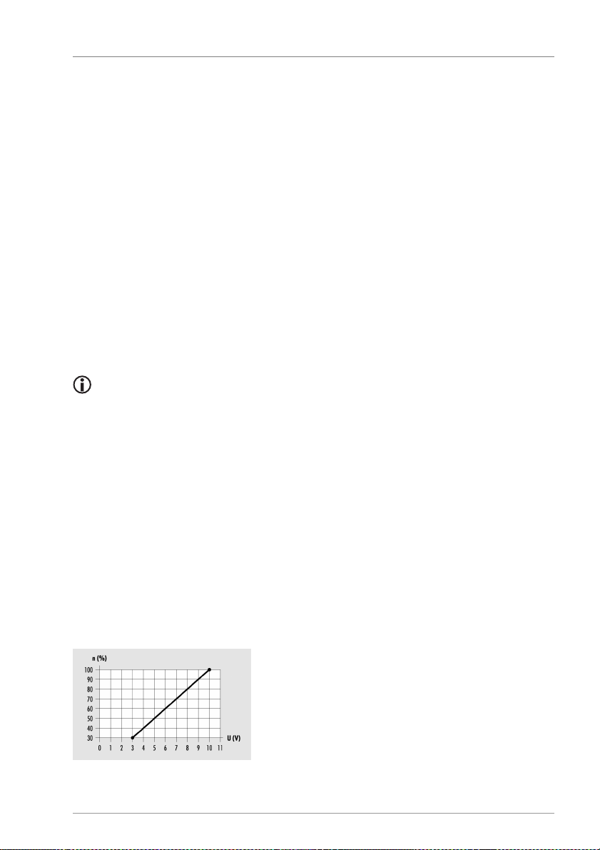
a 0–10 V analog signal to terminals HE1 and HE2.
Definitions for the output voltage (U):
• Pump off: 0.5 V < U < 1.0 V
• Speed control: Linear characteristic 3 V < U < 10 V (for a minimum pump output of
30 %)
The following diagram shows the power curve for the pump control system with analog
signal.
n (%) – Pump output
U (V) – Output voltage
Page 36
“Solar” function
36
Controlling HE pumps with PWM signals
In the case of the pump control system with PWM signal, the controller sends a PWM
signal (pulse width modulation signal) to terminals HE1, HE2 and HE3. The PWM signal can
be sent normally (not inverted) or inverted.
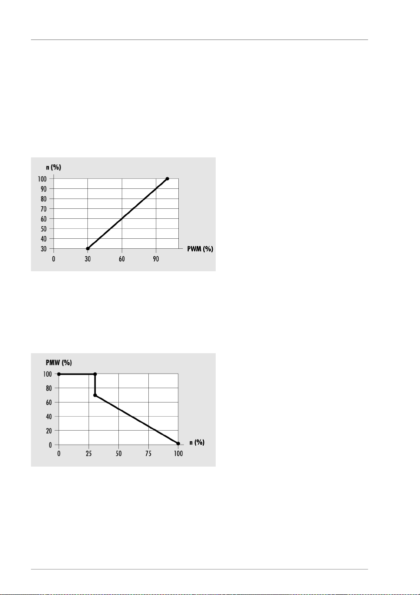
In the case of the pump control system with a non-inverted PWM signal, the nominal
speed of the pump (0–100 %) corresponds to the PWM signal (0–100 %). The following
diagram shows the power curve for the pump control system with a non-inverted PWM
signal.
n (%) – nominal speed of the pump
PWM (%) – non-inverted PWM signal
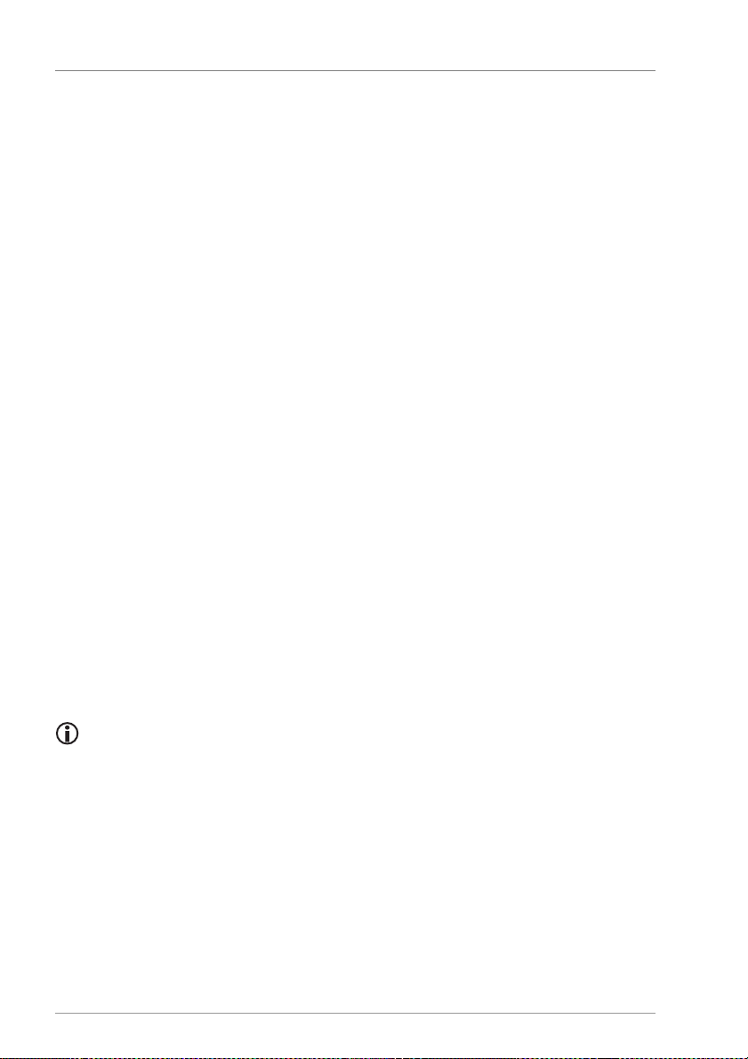
In the case of the pump control system with an inverted PWM signal, the nominal speed
of the pump (0–100 %) corresponds to the PWM signal (100-0 %). The following diagram
shows the power curve for the pump control system with an inverted PWM signal at a
minimum pump output of 30 %.
PWM (%) – inverted PWM signal
n (%) – pump speed sent by the controller
Page 37

“Solar” function
37
3.5 Setting the "Tube collector" function
If the solar power system is equipped with tube collectors, you have to activate this
function.
The control type is selected in the following menu item:
• Basic settings/Solar circuit/Tube collector/Function
− Time-controlled
− Radiation-controlled
− Control via temperature change
Time-controlled
You can set a time window and a pump runtime. In the time window the solar circuit
pump is switched on at certain specific intervals for the duration of the preset pump
runtime.
For this function you can set the following parameters:
• Basic settings/Solar circuit/Tube collector/Pump runtime
• Program/Solar circuit/Tube start time (stop)
Radiation-controlled
When the level of radiation reaches the preset radiation value, the solar circuit pump is
switched on for the duration of the preset pump runtime.
For this function you can set the following parameters:
• Basic settings/Solar circuit/Tube collector/Pump runtime
• Program/Solar circuit/Radiation
Control via temperature change
Whenever the collector temperature rises by a predefined value within a predefined
interval period, the solar circuit pump will be switched on.
For this function you can set the following parameters:
• Basic settings/Solar circuit/Tube collector/Time
• Basic settings/Solar circuit/Tube collector/delta T
3.6 Bypass function / external heat exchanger
When the criteria for switching on are met, the solar circuit pump is activated first in order
to warm up the collector circuit. This optimizes the energy generation process, especially
in larger solar power systems.
The storage tank is not charged until the temperature in the solar circuit is sufficient to do
so. The parameters for switching on and off are permanently set in the controller.
Page 38
Setting protective functions
38
4 Setting protective functions
In order to protect the solar power system against frost and overheating, the controller is
equipped with the following protective functions:
• "Collector protection" function
• "Storage tank protection" function
• "System protection" function
• "Pump protection" function
• "Heat exchanger protection"
• "Recooling" function
• "Drain-back" function
• "Anti-freeze protection" function
4.1 Setting the "Collector protection" function
This function protects the collector against overheating. If the preset collector protection
temperature is exceeded, the solar circuit pump switches on. The pump runs until the
temperature limit in the storage tank (95 °C) has been reached. This is done irrespective of
the preset maximum storage tank temperature.
If the temperature of the collector falls below the preset collector protection temperature
by 10 °C, the solar circuit pump switches off. The system will run again in normal
operating mode.
For this function you can set the following parameters:
• Basic settings/Solar circuit/Collector protection
4.2 "Storage tank protection" function
If a hydraulic layout with two storage tanks is used, the "Storage tank protection"
function will be automatically active and cannot be changed.
This function protects the storage tanks against overheating caused by faulty wiring or
any other possible faults. If the temperature limit is exceeded in one of the storage tanks
(95 °C), all switching outputs will be switched off. The storage tank will no longer be
charged.
When the temperature in the storage tank falls below the temperature limit again, the
system will be in normal operating mode again.
Page 39
Setting protective functions
39
ATTENTION
4.3 "System protection" function
This function is active at all times.
This function protects the system against overheating. If the temperature of the collector
rises above the preset system protection temperature, the solar circuit pump switches off.
When the temperature falls below the system protection temperature, the system will be
in the "Collector protection" function again. When the temperature falls below the
collector protection temperature, the system will be in normal operating mode.
For this function you can set the following parameters:
• Basic settings/Solar circuit/System protection
4.4 "Pump protection" function
This function is active at all times and cannot be changed.
If the solar circuit pump is not activated for 10 days, the controller starts the solar power
system automatically for 30 seconds.
4.5 "Heat exchanger protection" function
This function protects the heat exchanger against damage from frost. Whenever the
temperature on the collector falls below 5 °C, the heat exchanger pump switches on.
4.6 Setting the "Recooling" function
This function is automatically active if a hydraulic layout with external heat
exchanger is activated.
Risk of damage to the solar power system if operated with the "Recooling"
function in combination with reheating.
Make sure that reheating is not in operation before you activate the
"Recooling" function.
The "Recooling" function can be activated only if the "Collector protection"
function is active.
Page 40
Setting protective functions
40
This function protects the system against overheating in the following situations:
• If no hot water is used over an extended period of time (e. g. during a vacation)
• If the collector protection temperature is exceeded
If the temperature in the collector falls below the temperature in the storage tank (usually
at night), the solar circuit pump switches on. This recools the storage tank to a preset
temperature.
For this function you can set the following parameters:
• Basic settings/Solar circuit/Collector protection
• Basic settings/Solar circuit/Recooling
4.7 Setting the "Drain-back" function
The "Drain-back" function can be activated only if the "Recooling" function has
been deactivated.
With drain-back systems, the collector will be drained empty when the pump is off. To
pump the air out of the system, the pump will be operated at 100 % for an adjustable
time.
The "Min runtime" parameter is used to set a minimum pump runtime.
The "Condition time" parameter is used to set how long the conditions for switching on
and off must be active in order to take effect.
The fill time and the minimum runtime are reduced in the case of short switch-off times.
For this function you can set the following parameters:
• Basic settings/Solar circuit/Drain-back
• Basic settings/Solar circuit/Drain-back/Fill time
• Basic settings/Solar circuit/Drain-back/Min runtime
• Basic settings/Solar circuit/Drain-back/Condition time
You can choose between the control types "Temperature difference" and "Radiationcontrolled".
Temperature difference
In the case of the "Temperature difference" charging principle, the solar circuit pump is
controlled in such a way that the temperature difference between the collector and the
storage tank is maintained at as constant a level as possible.
Radiation-controlled
When the level of radiation reaches the preset radiation value, the solar circuit pump is
switched on for the duration of the preset pump runtime.
Page 41

Measuring the energy yield
41
For this control type you can set the following parameters:
• Program/Solar circuit/Radiation
4.8 Setting the "Anti-freeze" function
The "Anti-freeze protection" function can be activated only if the "Drain-back"
function has been deactivated.
This function protects the solar power system against the heat transfer fluid freezing. If
the temperature falls below the preset temperature, the solar circuit pump switches on.
If the preset temperature is exceeded, the solar circuit pump switches off. The system will
run again in normal operating mode.
For this function you can set the following parameters:
• Basic settings/Solar circuit/Anti-freeze protection
• Basic settings/Solar circuit/Anti-freeze protection/Sensor
• Basic settings/Solar circuit/Anti-freeze protection /Start temperature
• Basic settings/Solar circuit/Anti-freeze protection /Hysteresis
• Basic settings/Solar circuit/Anti-freeze protection/Min. runtime
5 Measuring the energy yield
The controller can calculate and display the energy yield of the solar power system. You
can assign yield measurement 1 to the solar circuit or set it as an independent yield
measurement.
The controller can calculate and display the energy yield of the solar power system as the
yield measurement in the solar circuit. To do so, it requires the following values:
• Flow rate
• Temperature difference between the collector and collector return flow temperatures
• Glycol type and glycol concentration in the heat transfer fluid
The energy output is displayed in the following menu item:
• Info/Balance values/Output
For the energy yield measurement you can set the following parameters:
• Basic settings/Yield measurement
You can choose from the following measurement methods:
• DFG (flow sensor)
• VFS (vortex flow sensor)
• DFA (flow indicator) – only yield measurement 1 in the solar circuit.
Page 42
Setting multi-function controllers (MFC)
42
Energy yield measurement in any hydraulic circuit is possible with yield measurement 1
(set as independent) and energy yield measurement 2.
This is also possible with energy yield 3 to 6 if flex 400 modules are connected optionally.
An additional flow sensor or vortex flow sensor is needed for energy yield measurement 2
and 3–6 (when flexboxes connected). This additional sensor must be installed in the
hydraulic circuit which is to be measured. Note the flow sensor specifications.
The two temperature sensors needed can be freely assigned to the function. It is thus
possible to measure the energy yield in any hydraulic circuit.
5.1 DFG (flow sensor)
The flow sensor measures the flow rate mechanically. It is located on the return flow pipe
of the solar power system. To determine the energy output with a flow sensor, the pipemounted sensor S4 must also be connected for temperature measurement.
5.2 VFS (vortex flow sensor)
The VFS measures the flow rate and the temperature. The following types can be installed
in the solar power system:
• VFS Type 1–20 (Measuring range of 1 to 20 litres/minute)
• VFS Type 2-40 (Measuring range of 2 to 40 litres/minute)
5.3 DFA (flow indicator)
Only with yield measurement 1 in the solar circuit.
In the case of this measurement principle the flow rate is measured just the once by a flow
indicator (flow indicator on the solar pump group – Tacosetter or adjustment valve) at a
pump output of 100 % (e. g. in manual mode). The measurement value is entered at the
controller. The flow indicator can then be removed again. The energy output is
determined on the basis of this measurement value.
If you use the "Flow indicator" measurement principle, you must make sure that
you do not operate the solar circuit pump with speed control. This would lead to
incorrect results for the energy yield measurement. Enter the value "100 %" in the
"Program/Solar circuit/Speed control" menu item.
Page 43

Setting multi-function controllers (MFC)
43
via a respective link
. R0 is not speed
-
controlled.
6 Setting multi-function controllers (MFC)
You can activate up to 6 multi-function controllers (MFC). The sensors and the output
(incl. HE1-HE3) can be freely assigned. The connected flex-modules can be also used for
that purpose.
The outputs are not linked to the PWM outputs (HE1-HE3). This can be achieved
You can assign the following functions to the multi-function controllers:
• "Heating" function
• "Cooling" function
• "Temperature difference controller" function
• "Threshold value switch" function
• "Return flow boost" function
• "Wood-fired boiler" function
• "Circulation" function
• "Alarm" function
• "Timer" function
• "HW reheating" function
• "Temperature range" function
• "Modulation" function
• "Cascade" function
• "Yield" function
• "Mixer" function (only MFC 1)
• "Valve" function (only MFC 2)
• "Storage tank cooling" function (only MFC 3)
You can select the function for the required multi-function controller in:
• Basic settings/MFC 1–6/Function.
6.1 Setting the "Cooling" function
In the case of the "Cooling" function, the switching output of the multi-function controller
switches on as soon as the preset switch-on temperature is exceeded. If the temperature
drops below the lower limit of the preset temperature range (hysteresis), the switching
output of the multi-function controller switches off.
Page 44

Setting multi-function controllers (MFC)
44
For this function you can set the following parameters:
• Basic settings/MFC 1-6/Source sensor, Output
• Program/MFC 1-6/Setpoint temperature
• Program/MFC 1-6/Hysteresis
• Program/MFC 1-6/Time 1–3: Start (Stop)
6.2 Setting the "Heating" function
In the case of the "Heating" function, the switching output of the multi-function controller
switches on as soon as the temperature falls below the preset switch-on temperature. If
the temperature rises above the upper limit of the preset temperature range (hysteresis),
the switching output of the multi-function controller switches off.
For this function you can set the following parameters:
• Basic settings/MFC 1-6/Source sensor, Output
• Program/MFC 1-6/Setpoint temperature
• Program/MFC 1-6/Hysteresis
• Program/MFC 1-6/Time 1–3: Start (Stop)
6.3 Setting the "Temperature difference controller"
function
In the case of the "Temperature difference controller" there is a measurement point at
both the source and the sink. If the difference between the temperatures of the two
measurement points exceeds a predefined value, the switching output of the multifunction controller switches on.
In addition, a minimum temperature can be set at the source and a maximum
temperature at the sink. If the maximum temperature is exceeded or the temperature falls
below the minimum temperature, the switching output of the multi-function controller
switches off.
For this function you can set the following parameters:
• Basic settings/MFC 1-6/Source sensor, Sink sensor, Output
• Basic settings/MFC 1-6/Speed
• Program/MFC 1-6/Tmax sink
• Program/MFC 1-6/Diff. controller max
• Program/MFC 1-6/Tmin source
• Program/MFC 1-6/Diff. controller min
• Program/MFC 1-6/Time 1–3: Start (Stop)
Page 45

Setting multi-function controllers (MFC)
45
6.4 Setting the "Threshold value switch" function
In the case of the "Threshold value switch" function, the switching output of the multifunction controller switches on as soon as the temperature reaches the preset switch-on
temperature. If the temperature drops below or rises above the preset temperature range
(hysteresis), the switching output of the multi-function controller switches off.
To use this function for heating, set the "Hysteresis" value to greater than 0. To use this
function for cooling, set the "Hysteresis" value to less than 0.
For this function you can set the following parameters:
• Basic settings/MFC 1-6/Source sensor, Output
• Program/MFC 1-6/Setpoint temperature
• Program/MFC 1-6/Hyteresis
6.5 Setting the "Return line boost" function
To save energy, energy is supplied to the heating return flow from the solar circuit or
storage tank. The mode of operation and relevant parameters are similar to those of the
"Temperature difference controller" function.
6.6 Setting the "Wood-fired boiler" function
This function allows you to re-heat the storage tank from a solid fuel boiler. The switching
output of the multi-function controller will be activated if the boiler temperature (source
sensor) plus the selected temperature range (hysteresis) exceeds the storage tank
temperature (sink sensor).
In addition you can also define a switch-on temperature (Tmin source). In this case the
pump will not start until the switch-on temperature has been reached.
With this function the storage tank will be heated to a maximum temperature of 95 °C.
For this function you can set the following parameters:
• Basic settings/MFC 1-6/Source sensor, Sink sensor, Output
• Basic settings/MFC 1-6/Speed
• Program/MFC 1–6/Tmin source
• Program/MFC 1-6/Hysteresis
6.7 Setting the "Circulation" function
This function provides you with hot water at all times. You can choose from the following
control types:
• Temperature-controlled
• Time-controlled
Page 46

Setting multi-function controllers (MFC)
46
Temperature-controlled
The switching output of the multi-function controller switches on as soon as the
temperature falls below the preset setpoint temperature. If the temperature rises above
the upper limit of the preset temperature range (hysteresis), the switching output
switches off. The sensor must be fitted in the circulation return line.
For this control type you can set the following parameters:
• Basic settings/MFC 1-6/Source sensor , Output
• Program/MFC 1-6/Setpoint temperature
• Program/MFC 1-6/Hysteresis
Time-controlled
The circulation pump is switched on and off in alternation within a preset time window.
You can configure the setting for the duration of the respective runtime and waiting time.
For this control type you can set the following parameters:
• Basic settings/MFC 1-6/Runtime, Output
• Basic settings/MFC 1-6/Waiting time
• Program/MFC 1-6/Time 1–3 start (stop)
6.8 Setting the "Alarm" function
In the case of this function, the switching output of the multi-function controller switches
on or off when there is a fault on the sensors used. For this function you can set the
following parameters:
• Basic settings/MFC 1–6/Output, Link.
6.9 Setting the "Timer" function
In the case of this function, the switching output of the multi-function controller switches
on within the preset time window. For this function you can set the following parameters:
• Basic settings/MFC 1–6/Output
• Program/MFC 1-6/Time 1–3 start (stop)
6.10 Setting the "HW reheating" function
With this function, the MFC output will be switched on when the hot water request is
active. The HW reheating can thus be implemented in layers using a three-way reversing
valve. No further parameters can be set for this function.
Page 47

Setting multi-function controllers (MFC)
47
6.11 Setting the "Temperature range" function
With this function you can set the upper limit and the lower limit of a temperature range.
The multi-function controller will switch only within this temperature range.
For this function you can set the following parameters:
• Basic settings/MFC 1–6/Source sensor, Output
• Program/MFR 1–6/Tlimit max.
• Program/MFR 1–6/Tlimit min.
6.12 Setting the "Modulation" function
With this function you can also request modulating heaters in accordance with the
required supply line temperature.
The operating range (linear curve) is defined by two vertexes. The first vertex is formed
from the parameters „Actuate min. [V]“ and „Demand min. [°C]“. The second vertex is
formed from the parameters „Actuate max. [V]“ and „Demand max. [°C]“.
If no request is active, 0V will be output.
If hot water is active (ch. 2.4), the voltage set in the "Actuate HW" parameter will be output
for the duration of the hot water processing at the output.
The analog output for the modulation is freely assignable. Outputs HE1 and HE2, and the
HE outputs from additionally connected flex 400 modules, are available.
The link is set by default to R0 (heat generator request), but it can be changed if required.
For this function you can set the following parameters:
• Basic settings/MFC 1–6/output.
• Basic settings/MFC 1–6/Delayed off period.
• Basic settings/MFC 1–6/Request min.
• Basic settings/MFC 1–6/Request max.
• Basic settings/MFC 1–6/Actuate min.
• Basic settings/MFC 1–6/Actuate max.
• Basic settings/MFC 1–6/Actuate HW.
6.13 Setting the "Cascade" function
With this function you can create a cascade of energy generators or enable actuation from
one output in accordance with a particular time.
The MFC must be linked by "and" to the output it is to follow.
When the leading output is switched on, the delay time will begin to run. When the time
has ended, the assigned output will be switched on.
Page 48

Setting multi-function controllers (MFC)
48
When the leadfing ouput is switched off, the MFC will also be switched off and reset to its
initial state.
For this function you can set the following parameters:
• Basic settings/MFC 1–6/output.
• Basic settings/MFC 1–6/Delayed off period
• Basic settings/MFC 1–6/Link
• Program/MFC 1–6/Waiting time
6.14 Setting the "Yield" function
With this function you can perform an energy yield measurement via an S0 interface. The
total yield and the day yield then appear in the "Info" menu.
For this function you can set the following parameters:
Basic settings/MFR 1–6/Input S00-S10, S12-S15 (Please note: the inputs S00, S12-S15
respond to +5V at the input)
• Basic settings/MFC 1–6/Pulse number per kWh
6.15 Setting the "Mixer" function (only MFC 1)
With this function you can boost the return line by mixer to the calculated maximum
supply line setpoint tempertaure of the heating circuits.
The multi-function controller uses different setpoint temperatures as reference:
1. Supply line: The currently highest supply line setpoint temperature is used as
reference. The mixer is controlled according to the source sensor (e.g. an external heat
source) and sink sensor.
If the source rises above the supply line setpoint temperature + hysteresis, the
function will become active and the mixer will adjust to the supply line setpoint
temperature + hysteresis.
2. Hot water: The hot water setpoint temperature is used as reference. The control
workflow is the same as point 1.
3. Temperature: An adjustable target temperature is used as reference. The mixer is
adjusted to this temperature according to the source sensor. If the source rises above
the sink setpoint temperature + hysteresis, the function will become active and the
mixer will adjust to the source setpoint temperature + hysteresis.
For this function you can set the following parameters:
• Basic settings/MFC 1/Target type
• Basic settings/MFC 1/ Output 1 (mixer open), Output 2 (mixer closed)
• Basic settings/MFC 1/Source sensor, sink sensor
Page 49

Setting multi-function controllers (MFC)
49
• Basic settings/MFC 1/ Mixer parameters (total actuating time, actuating time, cycle
time)
• Program/MFC 1/Hysteresis
An example layout can be found in the document Hydraulic layouts.
6.16 Setting the "Valve" function (only MFC 2)
With this function you can boost the return line by valve in accordance with the calculated
maximum supply line setpoint temperature of the heating circuits.
The multi-function controller uses the currently highest supply line setpoint temperature
as reference and switches the valve in accordance with the source sensor (e.g. an external
heat source).
If the source rises above the HC supply line setpoint temperature + hysteresis, the
function will become active and the valve will be actuated.
If the source drops below the HC supply line setpoint temperature, the valve will be
switched off.
For this function you can set the following parameters:
• Basic settings/MFC 2/Source sensor
• Basic settings/MFC 2/Output
• Basic settings/MFC 2/Delayed off period
• Basic settings/MFC 2/Link
• Program/MFC 2/Hysteresis
6.17 Setting the "Storage tank cooling" function (only
MFC 3)
With this function you can cool the storage tank via a heating circuit.
No output is assigned to this MFC. If the temperature rises above the set storage tank start
temperature, the respective heating circuit pump will be switched on and the mixer
controlled accordingly. In this way the storage tank can be cooled when there is suprplus
solar energy, and stagnation of the solar power system can be prevented.
The function will end when the temperature drops below the set storage tank stop
temperature.
Page 50
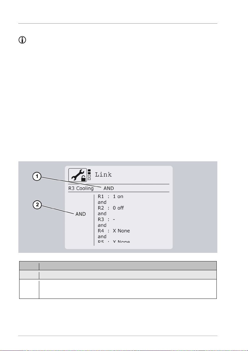
Setting multi-function controllers (MFC)
50
Pos. Description
1 AND/OR logic between R3 and the remaining outputs
2 AND/OR logic between the individual outputs.
any are connected.
This function makes sense for systems with a solar combination storage tank.
You must set the respective radiator thermostats by hand in order to prevent
unwanted heating of the rooms in the summer.
For this function you can set the following parameters:
• Basic settings/MFC 3/Heating circuit
• Basic settings/MFC 3/Source sensor
• Basic settings/MFC 3/Start temperature
• Basic settings/MFC 3/Stop temperature
• Basic settings/MFC 3/Delayed off period
6.18 Setting the logical link
In principle, all MFCs can be linked with other outputs. This means that the status of
another output will influence the control operation of the respective MFC.
Example for MFC R3 with AND-AND logic:
This setting also defines the logic between the individual outputs of the flex modules if
Page 51
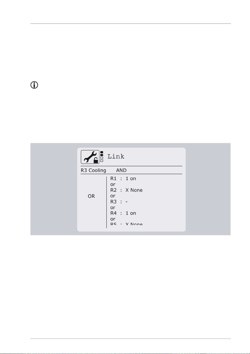
Setting multi-function controllers (MFC)
51
This would mean that MFC with output R3 is active only if:
• The switch-on conditions are met AND
• R1 is on (1) AND R2 is off (0).
R3, R4, R5, R6, R7, R0, HE1, HE2 and HE3 do not need to be taken into account (x).
Its own output (in this case R3) cannot be edited.
The value "10xxxxxxxx" is entered in the menu point Basic settings/MFC/Link. Assignment:
R1 R2 R3 R4 R5 R6 R7 R0 HE1 HE2 HE3
1 0 x x x x x x x x x
Example for MFC R3 with AND-OR logic:
This would mean that MFC with output R3 is active only if:
• The switch-on conditions are met AND
• R1 is on (1) OR R4 is on (1).
With the OR link there is no "0" selection.
The value „1xx1xxxxxxx“ is entered in the menu point Basic settings/MFC/Link.
Assignment:
R1 R2 R3 R4 R5 R6 R7 R0 HE1 HE2 HE3
1 x x 1 x x x x x x x
Page 52
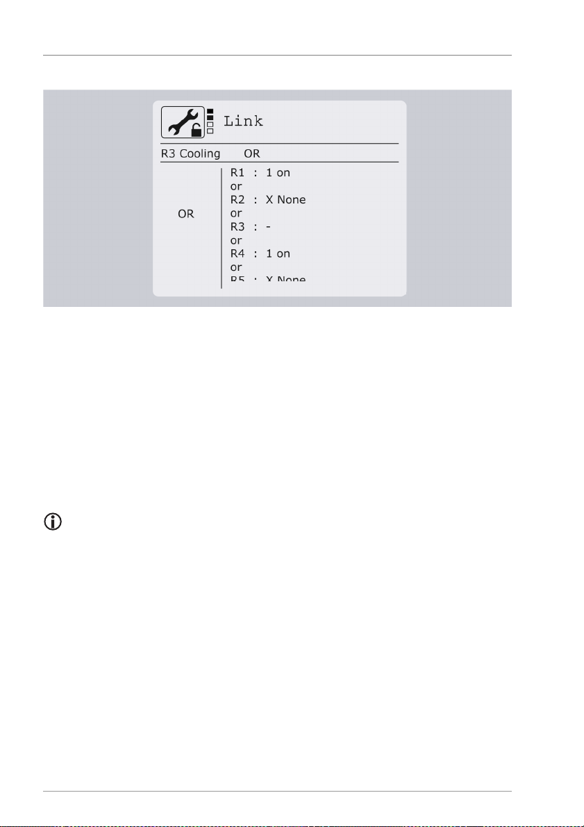
Setting multi-function controllers (MFC)
52
1336B-TB009-12B-E
Example for MFC R3 with OR-OR Logic:
This would mean that MFC with output R3 is active only if:
• The switch-on conditions are met OR
• R1 is on (1) OR R4 is on (1).
The value „1xx1xxxxxxx“ is entered in the menu point Basic settings/MFC/Link.
Assignment:
R1 R2 R3 R4 R5 R6 R7 R0 HE1 HE2 HE3
1 x x 1 x x x x x x x
If you change the link type, the set links will be deleted.
 Loading...