


User Manual Page 1 of 22 Version 25
User Manual

User Manual Page 2 of 22 Version 25

User Manual Page 3 of 22 Version 25
Contents
1 General ................................................................................................................................................... 4
1.1 Identification of the User Manual .............................................................................................................. 4
1.2 Importance of the User Manual ................................................................................................................. 4
2 Identification and Specification, General Warnings ............................................................................ 4
2.1 Identification and specification .................................................................................................................. 4
3 Safety Information................................................................................................................................. 5
3.1 Secure installation of the machine ............................................................................................................. 5
3.2 Safe training ............................................................................................................................................. 5
3.3 Indications and contra-indications ............................................................................................................. 6
3.3.1 Indicators ................................................................................................................................... 6
3.3.2 Relative contra-indicators ............................................................................................................ 6
3.3.3 Mandatory contra-indicators ....................................................................................................... 6
3.4 Use and area of application ....................................................................................................................... 7
4 Dimensions and Weights ....................................................................................................................... 7
5 Maintenance and Care ........................................................................................................................... 8
6 Prepare the Product for Use .................................................................................................................. 8
6.1 Transport .................................................................................................................................................. 8
6.2 Storage ..................................................................................................................................................... 8
6.3 Installation ................................................................................................................................................ 8
6.3.1 Protective cover .......................................................................................................................... 8
6.4 Before use check ....................................................................................................................................... 9
7 Optional Accessories .............................................................................................................................. 9
7.1 compass Additional Weight Increments 4x1,0 kg or 4 x 2,0 kg .................................................................. 9
7.2 Weight stack upgrade ............................................................................................................................... 9
7.3 Range of Motion Limiter ........................................................................................................................... 10
7.4 Lumbar Cushion for compass 600 ............................................................................................................. 10
7.5 Laser Pointer for Exact Positioning ............................................................................................................. 10
7.6 compass Balance Board for the functional press ........................................................................................ 10
7.7 Foot Support for untraining Leg for the Functional Press ............................................................................ 10
7.8 Foot Support for untraining Leg for the functional press ............................................................................ 11
7.9 Stabilisation belt for the shoulder blade fixator / shoulder press ................................................................. 11
7.10 Adjustable Foot Support for abductors / adductors .................................................................................... 11
8 Training Manual ..................................................................................................................................... 11
8.1 General training recommendations ........................................................................................................... 11
8.2 compass 600 Leg Press / calves.................................................................................................................. 13
8.3 compass 600 Leg Extension/Curl ............................................................................................................... 14
8.4 compass 600 Ab-/Adduction ..................................................................................................................... 15
8.5 compass 600 Trunk Extension/Flexion ........................................................................................................ 16
8.6 compass 600 Butterfly/Butterfly Revers ...................................................................................................... 17
8.7 compass 600 Pulldown/Dip ....................................................................................................................... 18
8.8 compass 600 Chest Press/Rowing Machine ................................................................................................ 19
8.9 compass 600 Shoulderpress / Vertical Row ................................................................................................ 20
9 Warranty and Guarantee ...................................................................................................................... 21

User Manual Page 4 of 22 Version 25
1 General
You have decided to purchase one of our sequence training machines. We thank you
for the trust you have shown us.
Compass ® 600 weight training machines are constructed considering recognised biomechanical knowledge, as well as anatomical and physiological considerations and are
used to train the different muscle groups.
The devices have undergone comprehensive safety checks, to prevent possible injury. To
ensure careful, safe and proper use read this User Manual with all safety instructions
and warnings before using this training machine for the first time.
1.1 Identification of the User Manual
- The version is specified on the last page.
- If due to modifications a revision by the manufacturer is required, this is implemented by the manufacturer
and identified with a new version number.
1.2 Importance of the User Manual
The User Manual is a part of the product purchase and should be kept and updated for the lifetime of the
equipment.
The Manual should be passed on to future English speaking owners of the equipment. For subsequent owners
with other language please request separate operating instructions.
The user has to ensure that any necessary supplements received are placed into the Manual.
The points mentioned above are also valid for any accessories. In the event of loss of the Manual, another can be
ordered for a fee from the manufacturer at any time upon written request.
2 Identification and Specification, General Warnings
2.1 Identification and specification
This Manual is valid for the following devices:
Item number
Identifier
10610600
compass 600 Leg Press
10689500
compass 600 Leg Extension/Curl
10609000
compass 600 Ab-/Adduction
10692100
compass 600 Trunk Extension/Flexion
10610700
compass 600 Butterfly/Butterfly Revers
10690500
compass 600 Pulldown/Dip
10645400
compass 600 Chest Press/Rowing Machine
10691500
compass 600 Shoulderpress / Vertical Row

User Manual Page 5 of 22 Version 25
3 Safety Information
3.1 Secure installation of the machine
Place the machine on a solid, level and non-slip surface and level the machine with
supporting material so that it does not wobble.
The area around the machine must be at least 1 metre larger that the movement
range of the machine, to ensure that the machine can be approached and egressed
from safely also in the event of an emergency. However, the safety areas can overlap;
see image.
The protective cover must not be removed.
The warranty is void if changes are made to the machine or if electronic controllers and measuring devices are
added that are not installed by authorised specialists of the manufacturer.
• Set the device only in dry areas (< 65% relative humidity, >0 < 45 °C room temperature).
• These training machines are only allowed to be used when the access and supervision is specially regu-
lated by the owner. The level of supervision depends on the user, taking into consideration their reliability, age, and experience, etc. The training machines are only allowed to be used when supervised by authorised specialist staff (e.g. graduate sports teacher, physical therapist) or after extensive instruction
through appropriate staff.
• The person training should always keep an eye on weight stack during the complete training to prevent
harm to third persons.
• Handicapped persons, children, or persons with cardiovascular complaints should not train without su-
pervision.
• Children are not allowed to use or to stay near the machine without supervision.
• During the training, nobody should be near moving parts, (weight block, guide slides, etc.). A safety dis-
tance around the machine (free space) of 1.3 metres should be ensured for persons and objects, to eliminate every risk of injury due to parts swinging out.
• Only use the machine for its intended purpose.
• With even the slightest hint of a fault, the machine should be shut down and immediately left. The fault
should be diagnosed and repaired. If necessary, inform or consult the manufacturer or service.
• Damage that reduces the functionality or that could lead to injuries should be repaired otherwise liability
is excluded.
• Do not grab moving bearings or rollers with your hands.
• When training, avoid using devices that cause electromagnetic radiation (e.g. cell phones, radio anten-
nas, etc.).
3.2 Safe training
• Before starting training, the training fitness should be checked by an authorised person such as a physi-
cian. Please note point 3.3 contra-indicators.
• Please note that excessive training can be harmful.
• In the event of nausea or dizziness, the training should be stopped immediately and you should see a
doctor.
• Training with patients should only take place under the supervision of therapists.
• Training on the machine is only allowed when the skin is not damaged.
• When training close-fitting, lightweight sports clothing is to be preferred that cannot be caught in parts
of the machine.
• Before you start any exercise, make sure that all locking pins on the adjustable parts of the relevant
training machine are completely latched and tightened. Do not pull any of the locking pins during the
course of any exercise.
• Check the machine before starting training that it is secure; there are no defective parts and no signs of
other manipulation. If you notice any deficiencies or are not sure, ask the supervisor before you start
training.
• Before every training, make sure of the correct biomechanical positioning with reference to the pivot
point, the joint adjustment, etc., and also ensure that the adjustment mechanism is correctly latched. No
part of the adjustment mechanism should protrude.
• Be very careful when making any adjustments to the machine. Read the corresponding section of the
User Manual.

User Manual Page 6 of 22 Version 25
3.3 Indications and contra-indications
3.3.1 Indicators
Spinal column syndrome with significant symptoms:
• Proven slipped disc (also after surgery) and considerable protrusions beyond the acute stage
• Proven degenerative changes
• Proven spondylolysis and spondylolisthesis
• Spinal column injuries within the framework of conservative and postoperative treatment
• For recurrent disc complaints with significantly reduced capacity for work
• Proven scoliosis and amplified spinal deformities
3.3.2 Relative contra-indicators
• Tumour disease
• Inadequately medically controlled hypertension
• Stress labile coronary heart disease (CHD)
• Relative cardiac insufficiency
• Short interval phases of rheumatism
• Osteoporosis with a bone density up to 80% of the age average
• Slipped discs and protrusions up to 3 months without any surgical indications
• Glaucoma
• Diabetes
• Instable psyche
3.3.3 Mandatory contra-indicators
• New fractures (up to 4 months)
• Acute results found through surgery
• Condition after abdominal surgery (up to 4 months)
• Condition after gynaecological surgery (up to 4 months)
• Incisional hernias
• Deformity of the spinal column:
o Spina Bifida with more than one spinal column segment affected
o Floride Scheuermann's disease
o Scoliosis with growth greater than 30 according to Cobb
• Severe vascular disease
o Aneurysm of the Aorta
o Pulmonary embolism
o Thrombosis of large veins
o Celebral ischaemia
• Severe heart and cardiovascular conditions
o With cardiac insufficiency
o Unstable angina pectoris
• Severe inflammatory conditions in an acute episode
o Such as PcP or Morbus Bechterew
• Osteoporosis with a bone density of less than 80 % of the age average
• Severe slipped disc with leg discomfort
o Indications for surgery (acute nerve irritation)
o Progressive neurological symptoms
• Detachment of the retina
• Infectious diseases
• Progressive instability of spinal column
• Hypertensive Carotid Sinus Syndrome
• Tinnitus
• Spondylolisthesis (> Meyerding Classification II)
• Root and spinal cord symptoms (with considerable neurological symptoms)
If medication is being taken then a doctor should be consulted.

User Manual Page 7 of 22 Version 25
3.4 Use and area of application
The system is designed to be used in the following fields of application:
•
Orthopaedic and physiotherapy departments in clinics, hospitals and care facilities
•
Rehabilitation clinics
•
Works clinics and outpatient clinics
•
Careers advisory and training centres
•
Medical research facilities
•
Industrial medicine
•
Health centres and health insurance companies
•
Fitness and prevention centres
•
Recreational Sports Consulting Centres
•
Professional sports training centres
•
Sports medicine
4 Dimensions and Weights
Item number
Identifier
Userweight
Weight block
Standard/Option
Weight
Device
(max)
Dimensions
CM (max.)
Lower Extremities
10610600
compass 600 Leg Press
250 kg
160 kg /
250 kg
700 kg
L 246
W 113
H 184
10689500
compass 600 Leg Extension/Curl
250 kg
80 kg / 100 kg
460 kg
L 132
W 113
H 165
10609000
compass 600 Ab-/Adduction
250 kg
80 kg / 100 kg
400 kg
L 149
W 120
H 165
Torso / back
10692100
compass 600 Trunk Extension/Flexion
250 kg
80 kg / 100 kg
420 kg
L 137
W 113
H 165
Upper extremities
10610700
compass 600 Butterfly/
Butterfly Revers
250 kg
80 kg / 100 kg
425 kg
L 122
W 163
H 184
10690500
compass 600 Pulldown/Dip
250 kg
80 kg / 100 kg
565 kg
L 154
W 133
H 184
10645400
compass 600 Chest Press/
Rowing Machine
250 kg
80 kg / 100 kg
425 kg
L 132
W 161
H 165
10691500
compass 600 shoulderpress/
vertical row
250 kg
80 kg / 100 kg
565 kg
L 154
W 133
H 184

User Manual Page 8 of 22 Version 25
5 Maintenance and Care
Despite the excellent quality of the machine, you should make the following checks regularly (4 - 6 weeks) for
safety reasons:
Check all parts of the machine, in particular parts that can wear out such as rollers, screws, bolts, ropes, straps
and their mountings for strength and damage. In order for the machine to remain technically sound any parts
damaged due to wear and tear should be immediately replaced with original parts and the machine should not be
used until it is repaired.
Clean the glass panels and the frame parts regularly with a damp cloth and mild soap to remove any sweat residues. After a training session, disinfect the cushion with commercially available wipe disinfectants.
To maintain the guide rails (weight plates) we recommend that you clean them at regular intervals and then treat
them with maintenance oils (Fin Super "dry lubricant"). This you can obtains these directly from proxomed®.
As far as are present, the bowden cables, locking pins and setscrews should also be greased.
Note!
If you do however fine some unexpected damage stop the training immediately. If there is a problem, which you cannot easily solve then contact the proxomed® Service. The authorised Service will
provide you with quick and competent help or give you instructions on how to do this. At the end of
the Medical Product Book, you will find the form "Repair Order / Fault Reporting". This template is
to copy, fill out, and fax. Please fill out this form with the information you have and describe the
fault as accurately as you can.
6 Prepare the Product for Use
6.1 Transport
The machine was delivered by our employees, assembled, and tested.
6.2 Storage
The storage location of the machine should be dry, free from seawater and dust-proof, with a storage temperature between +5 °C to 45 °C. Protect the machine from bumps, scratches, and moisture.
6.3 Installation
The machines must be horizontal on a flat, stable and impact-resistant surface. The surface, in relation to the
floor covering and static, must be capable of withstanding the weight of the machine and the body weight of
the trainee (see Chapter 2.1). If the surface is uneven then even-out using suitable material (e.g. high-strength
plastic) to achieve a level surface. In this case, it is important to make sure that the material used to even-out the
surface cannot rust.
We recommend that you use rubber cladding under the machine to dampen. Keep in mind, if you use PVC or
laminate flooring the rubber sheets can react with the surface. Please use appropriate filling materials as additional padding, because if there is damage due to a lack of padding this cannot be reimbursed by proxomed®.
Avoid harsh, abrupt putting down of the machine. An important prerequisite for the proper functioning of the
machine is the orientation with a spirit level. The machine is useable when freestanding.
Avoid positioning the machine in busy areas such as near doors and passageways.
6.3.1 Protective cover
The trim of the compass® 530 machine is made of plastic in frosted glass appearance. The training machine only
meets the legal requirements for use in training with the protective cover on.
The protective covers affixed by the manufacturer must not be removed or altered; as otherwise, the standards
for training are not met.

User Manual Page 9 of 22 Version 25
6.4 Before use check
Check prior to using, the proper condition of the following components:
- Flat belts for visible damage, particularly the respective end mount.
- Locking pins for correct functioning, the detent knob must engage on its own.
- Stability of the machine at the place of use.
- Undamaged protective cover.
- Fixed screw connections.
- Smooth movement guiding.
- Firm hold of the insertion pin.
- Secure locking of the pneumatic compression spring to the position settings.
7 Optional Accessories
7.1 compass Additional Weight Increments 4x1,0 kg or 4 x 2,0 kg
Correct usage
With the fine adjustments that can be optionally obtained, additional load stages
are possible, the load can be increased by
0 kg, 1 kg, 2 kg, 3 kg, 4 kg, or with the 2 kg version with loads of
0 kg, 2 kg, 4 kg, 6 kg, 8 kg.
Article number
• compass Additional Weight Increments 4x1,0 kg: No. 10181600
• compass Additional Weight Increments 4x2,0 kg: No. 10692500
The additional weight adjustment function
The additional weight adjustment may only be adjusted in the unloaded condition (the weight stack has
no load).
By turning the knob of the additional weight adjustment, this can be set to the relevant position and then
it engages. The following positions are possible.
Position 4 x 1 kg or 4 x 2 kg
0 0 kg 0 kg
1 1 kg 2 kg
2 2 kg 4 kg
3 3 kg 6 kg
4 4 kg 8 kg
According to the built-in option, the set weight increase by the value of the additional weight adjustment.
7.2 Weight stack upgrade
Correct usage
With the optional upgrade of the weight block, the machine can be extended by a
further four weight positions. Depending on the machine it can be 4 x 5kg = 20kg
(80 to 100kg extension)
or by 4 x 10kg = 40kg (160 to 200kg extension)
Article number
• Upgrade to 100 kg Stack Weight: No. 11210400
• Upgrade to 200 kg Stack Weight: No. 11210300

User Manual Page 10 of 22 Version 25
7.3 Range of Motion Limiter
Correct usage
To avoid unwanted movement that could lead to injuries, a mechanical stop can
be set via the movement limiter.
Article number
• Range of Motion Limiter: No. 10692700
7.4 Lumbar Cushion for compass 600
Correct usage
The lordosis cushion support the best possible spinal posture, in particular for persons with postural instability. Available for the following machines 10611900,
10689500, 10609000, 10690800, 10645400
Article number
• Lumbar Cushion for compass 600: No. 10692800
Function of the Lordosis cushion
The lordosis cushion, can be infinitely adjusted. It is magnetically attached and
therefore easily removable. If it is not needed, it can be easily removed and
"parked" anywhere on a magnetic part of the machine.
7.5 Laser Pointer for Exact Positioning
Correct usage
The laser pointer projects the axis of rotation of the lever arm to the pivot point on
the body of the person training. So they are precisely positioned and optimal biomechanics can be assured. Available for the machines 10689500, 10692100
Article number
• Laser Pointer for Exact Positioning: No. 10692300
7.6 compass Balance Board for the functional press
Correct usage
With the optionally available circle, proprioceptive training of the lower extremities
can be undertaken.
Article number
• compass Balance Board for the functional press: No. 10096200
Function compass Balance Board
The circle is pushed into the rail provided and fixed by turning in a clockwise direction. To adjust turn in a counter-clockwise (left turn) to release the fixation (half a
turn is sufficient) and then the circle can be moved.
7.7 Foot Support for untraining Leg for the Functional Press
Correct usage
When training with just one leg there is the option to shut off the unused leg.
Article number
• Foot Support for untraining Leg for the functional press: No. 10693200

User Manual Page 11 of 22 Version 25
7.8 Foot Support for untraining Leg for the functional press
Correct usage
In particular in neurological patients it may be necessary, to fix a leg or both legs
against slipping from the base plate.
Another possible application is the requirement to allow a possibly stiff leg or a leg
that is restricted in movement to resonate with the machine so that the moveable
leg can be trained over the entire range of movement.
Article number
• Suspension device on the base plate with adjustable strap
for functional press: No. 10693200
7.9 Stabilisation belt for the shoulder blade fixator / shoulder press
Correct usage
Fixation of the pelvis over an adjustable stabilisation belt.
Article number
• Stabilisation belt: No. 10693100
7.10 Adjustable Foot Support for abductors / adductors
Correct usage
Optionally, the exercise can be done in an open or closed chain. The adjustable
footrest exercising in the closed chain.
Article number
• Adjustable Foot Support for abductors / adductors, left & right, adjusta-
ble: No. 10692900
8 Training Manual
The positioning of the patient must always be carried out with the greatest possible care, because quality and
effectiveness of the exercise execution depend largely from a correct initial position.
For most of the machines training is in a sitting position, but sometimes also in a lying or standing position. The
back, the lumbar spinal column in particular, should be stabilised as best as possible during the exercise execution. If present, the backrest used to stabilise the spine column. If necessary, use the optional lordosis pillows.
The machine axes and pivot points must be as precise as possible to the axes of movement of the joints to be
exercised to avoid any compression and shearing forces. The machines can be used for exercising the extremities on either side or just one side.
The lever arm length can be individually adapted to the anatomical conditions of the trainees.
The training position decided on by the therapist or trainer can be reproduced later for independent training,
because all adjusting devices are fitted with a scale, and on each machine, the position settings are alphabetically numbered (A, B, C, etc.) in a meaningful way.
The weight should be selected so that the patient/trainee can perform the training without evasive movements.
The load is selected on the machine with pin on the weight block. A fine adjustment to the weight can be set
using the supplied auxiliary weights (optional).
There is the possibility to stabilise the customer/client during training.
8.1 General training recommendations
Before starting, the training program the patient should warm-up for example on a stationary bicycle ergometer, followed by stretching exercises to prepare the appropriate muscles for the load.
With limited mobility or if pain is present, training should only be done where possible in the painless range. In
this case, the range of movement can be limited with the movement limiter (optional) and the starting angle

User Manual Page 12 of 22 Version 25
can be individually and precisely defined. If there is any discomfort the exercise should be stopped immediately
and if necessary, a doctor is to be consulted.
The machines allow a patient/client to exercise one or both legs, or one or both arms.
The range of movement should be slow and controlled, while ensuring the correct execution of the movement.
The load intensity at the start of training should be deliberately selected to be light. The load is then increase
gradually, to avoid excessive loads, which can lead to problems and pain with patients/trainees.
The weight can be moved explosively, with quick powerful exercises, but only with persons that can be correspondingly loaded. A controlled motion control must also be guaranteed with this training method to avoid
stress and injury. As a rule, concentric and eccentric modes of operation of the muscles should be combined.
Different training methods are applied. If the repetitive training method is used, several training series are carried out with corresponding pauses. The training intensity is based on the carrying capacity of the injured structure, the rehabilitation phase of the patient, and the training goals.
Here priority can be given to the adaptation and habituation of the injured structure (connective tissue, cartilage, tendons, ligaments, and joint capsule) to training with a load with low intensity, before the training of
special power capabilities - such as stamina training or maximum power - with increasing intensity.

User Manual Page 13 of 22 Version 25
8.2 compass 600 Leg Press / calves
Correct usage
The machine enables a functional training of the
leg and the hip stretch muscles depending on
patient positioning in the closed system. This
machine trains the leg extension in a functional
starting position. The movement takes place in a
closed system, the entire muscle chain trained.
Specific positioning of the person training (order under the assumption that the person training does
the adjustment)
Set the angle according to the aim of the exercise. Rotate the handle to the left to
release the clamp, and at the same time release the adjustment by holding the base
plate and pulling the rotating handle. CAUTION This is a two handed operation.
With one hand, the base plate is held firm and the other hand is used to release the
turning/locking pins for adjustment.
After completing this setting, all other settings can be made in the seated position.
Adjust the backrest angle. Press (tilt) the release lever to the inside. The backrest can
be set flat or in a vertical position and in 10° steps. Training can take place either
horizontally or in a sitting position.
Adjust the starting position (seat carriage) by pulling on the locking pin, according to
the exercise selection, (functional press or calves) and the movement of the person
training.
Fixation of the body posture with the shoulder support. To do this press the release
lever and pull the shoulder pad onto the shoulder.
The range of movement limiter (optional) for the end position is located above the
weight blocks and is adjusted by loosening the mounting bolt.
Reactive bounce power training with low weights should only be done with the
supervision of a therapist! When doing so make sure that the carriage does not
bang against the end stop.
Stressed muscles
Quadriceps femoris muscle gluteus maximus muscle ischiocrurales muscle gastrocnemius muscle
abductores muscle adductors muscle erector spinae muscle
User Manual Page 14 of 22 Version 25
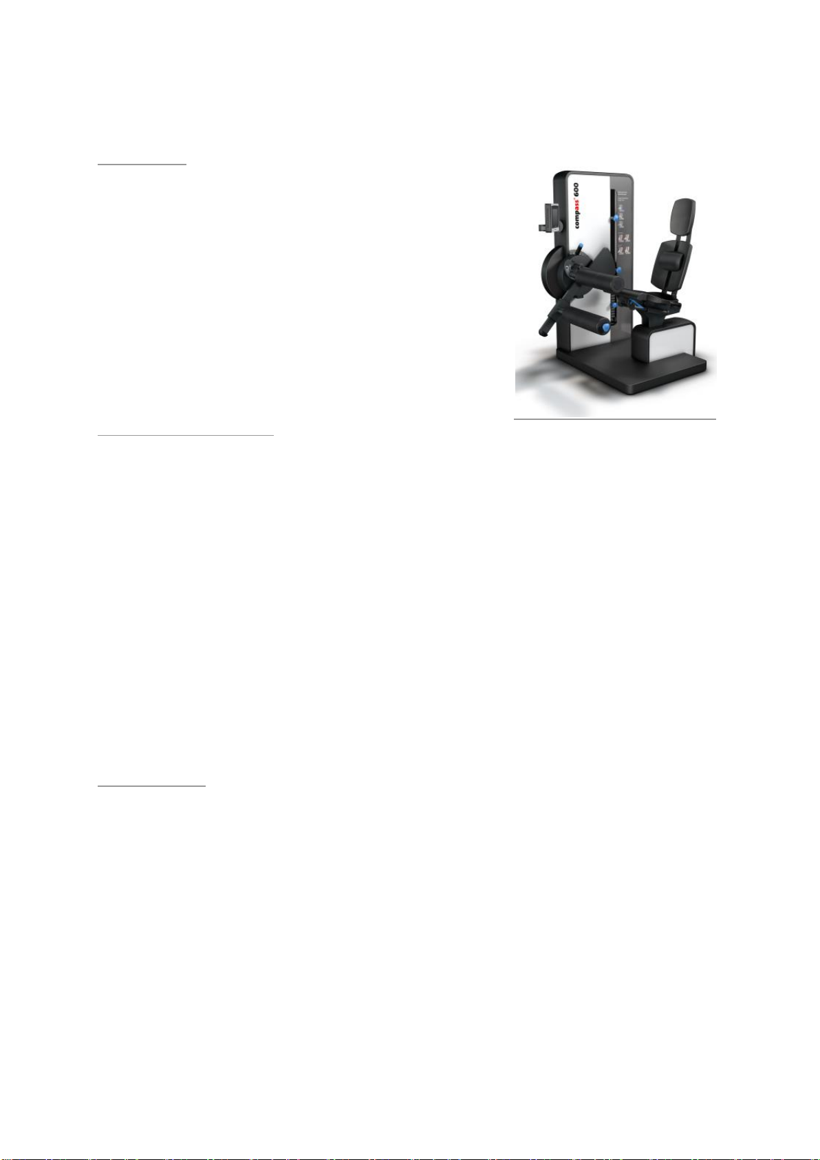
8.3 compass 600 Leg Extension/Curl
Correct usage
With this machine, the leg extension and the leg
flexor muscles can be trained in the sitting position. One or both legs can be trained. It is possible to train both concentrically and eccentrically.
Specific patient positioning
The patient sits on the seat and leans against the backrest. Depending on the length of the thigh, the seat
is now pushed as far back or forward as possible until the rotation axis of the machine lines up with the
movement axis of the knee-joint (imaginary line through both femoral condyles); full contact must be
made with the backrest and the lordosis pillows. The freely adjustable lordosis pillows (optional) are individually adapted to the size of the patient. The fine adjustment of the pivot axis is carried out using the
spindle below the seat above the setting for the height-adjustable thigh support cushion. In order to avoid
any shearing forces, this adaptation should be made as precisely as possible. The starting position for the
training of the knee extension and the knee flexor muscles is individually adjustable in 10° steps. To do
this, press the push-button of the guide rod on the cam plate and bring the lever arm to the desired position and release the push-button allowing the bolts to go back into position.
The shinbone padding can be placed either near to the joint (proximal) or above the ankle joint (distal). In
the early phases of rehabilitation, the training can be dosed so that the joints are not overly stressed. For
training of the leg flexor muscles when sitting, the thigh is fixed by the moveable thigh support cushion.
Located next to the right thigh of the trainee is the releasing lever for the pneumatic compression spring.
Activate this and press the lateral femoral condyle to fix into position and then release the lever again for
fixing. The weight load is fixed from the machine using a pin on the side-oriented block. The range of
movement limiter (optional) for the end position is located above the weight blocks and is adjusted by
loosening the mounting bolt. There is also the option to work in a closed chain, where the feet can be
placed on an extended lever arm shelf. The base plate is infinitely adaptable to the different length of the
lower leg (art. 37031).
Stressed muscles
quadriceps femoris muscle (extension movement) biceps femoris muscle
semimembranosus muscle semitendinosus muscle popliteus muscle
sartorius muscle gracilis muscle (flexion movement)

User Manual Page 15 of 22 Version 25
8.4 compass 600 Ab-/Adduction
Correct usage
With this machine, all muscle groups, responsible
for the abduction and adduction of the legs on
the body are effectively trained. These muscle
groups have a stabilising function for the pelvis
and hip and also for the knee-joint.
Specific positioning of the person training (order under the assumption that the person training does
the adjustment)
Training is in the sitting position. The patient should be positioned so that the
back remains in full contact to the backrest during the entire movement. The
backrest can be tilted with a pneumatic compression spring, so that training
can be in the sitting or the half-lying position. For this purpose, there is a lever
on the left side of the trainee under the seat, which can be operated to adjust
the backrest. After the release of the lever, the backrest is fixed again.
The upper and lower legs are placed on the side padded leg support. The
(optional) footrests for training in the closed movement path are customised to the size of the patient or client.
The leg rests can be brought to the desired starting position by turning
them, this means for the adduction movement outward, for the abduction.
movement inward.
The starting position is adjusted depending on the mobility of the individual
patient. The setting is possible in 10° steps. Pull the release lever (on the right
when seated) and move to the desired position.
Let go of the release lever. The movement mechanism snaps into the next
available position.
The range of movement limiter (optional) for the end position is located above
the weight blocks and is adjusted by loosening the mounting bolt.
Stressed muscles
Adductors: Adductor magnus muscle adductor longus muscle
adductor brevis muscle pectineus muscle gracilis muscle
Abductors: Gluteus maximus muscle gluteus medius muscle
gluteal minimus muscle tensor fasciae latae muscle
sartorius muscle piriformis muscle

User Manual Page 16 of 22 Version 25
8.5 compass 600 Trunk Extension/Flexion
Correct usage
With this machine, the dorsal and the ventral
trunk muscles can be trained.
Specific positioning of the person training (order under the assumption that the person training does
the adjustment)
The training takes place in a closed system, i.e. the footrest is used to hold the
body, in particular the pelvis in position during the exercise.
The seat with the pneumatic compression spring can be adjusted by using the
actuator below the seat. Adjust the height of the seat, so that the iliac crest is at
the height of the axis of rotation of the lever arm. For the exact positioning use
the laser pointer (option).
Set the padding for the training arm to the desired height after loosening the
setscrew. For the extension movement the upper edge of the padding should be
at the position of the spinae scapulae, for the flexion movement it should be just
below the collar bones.
To set the starting position press the release lever to left (tilt), bring the lever arm
to the desired position and let the lever go back into place. The notches are in
10° steps.
The range of movement limiter (optional) for the end position is located above the weight blocks and is adjusted by loosening the mounting bolt.
Stressed muscles
Erectores muscle longissimi muscle interspinales muscle (back extension)
Rectus abdominis muscle obliquus externus abdominis muscle
obliquus internus abdominis muscle (back curler)

User Manual Page 17 of 22 Version 25
8.6 compass 600 Butterfly/Butterfly Revers
Correct usage
With this machine, all muscle groups of the back
and of the thoracic spine that make sure the
spinal column is kept upright and to stabilise the
shoulder joint are trained. Likewise, all muscle
groups are trained that are responsible for the
ventral stabilisation of the pectoral girdle.
Specific positioning of the person training (order under the assumption that the person training does
the adjustment)
The seating height is set depending on the size of the individual patient. The
seat with the pneumatic compression spring can be adjusted by using the
actuator below the seat. The legs are positioned in front of the body on the
footrest.
The spinal column should be in contact with the backrest for the entire exercise execution. A freely adjustable lordosis pillows are adjusted individually
depending on the size of the patient.
When exercising make sure that, the cervical spine remains in the neutral
position and the head is not moved forward. The setting of the round padding or the lever arm, allows the individual adjustment for different shoulder
widths and arm lengths of the person training. The distance of the padding
to the machine axis depends on the arm length of the patient or client and
can be individually adapted after actuating the release lever.
The starting position is adjusted via the locking pins in 10° steps.
The grab handles (optional) can be adjusted accordingly, loosen the fastening
screw and adjust the handles to the required height, retighten the screw.
I
The range of movement limiter (optional) for the end position is located above
the weight blocks and is adjusted by loosening the mounting bolt.
Stressed muscles
Pectoralis major muscle (breast stabiliser) Rhomboideus muscle trapezius muscle
deltoides muscle teres minor muscle infraspinatus muscle (posture stabiliser)

User Manual Page 18 of 22 Version 25
8.7 compass 600 Pulldown/Dip
Correct usage
With this machine, the shoulder blade fixator
muscles can be trained that are of particular importance for a spinal column friendly upright
posture. With the second function, can also here
the pectoral girdle muscles be trained, which are
used for stabilising and supporting.
Specific positioning of the person training (order under the assumption that the person training does
the adjustment)
For the shoulder blade fixator exercise the seat height must be set low for
large persons, so that the movement of the person training can be over the
whole range of movement.
For the shoulder press exercise the seat height must be set high for large
persons, so that the movement of the person training can be over the
whole range of movement.
Adjust the seat accordingly by operating the release mechanism below the
seat. The legs are positioned in front of the body on the footrest.
When exercising make sure that, the cervical spine remains in the neutral
position and the head is not moved forward.
The setting of the starting position for each exercise, shoulder blade fixator
or shoulder press, is carried out by pressing the release lever (on the left
when seated). To do this, while holding the release lever move the handle
to the desired position and let go of the release lever. The movement
mechanism snaps into the closest position.
For person training whose body size differs from the average, there is an
additional basic setting possible by pressing the release lever (on the right
when seated). To do this, while holding the release lever, move the handle
either up or down (tilt) to the desired position and let go of the release
lever. The movement mechanism snaps into the closest position.
The range of movement limiter (optional) for the end position is located above the weight blocks and is adjusted by loosening the mounting bolt.
Stressed muscles
Latissimus dorsi muscle pectoralis major muscle subscapularis muscle
deltoideus posterior muscle teres major muscle serratus anterior muscle
biceps brachii muscle (shoulder blade fixator)
triceps brachii muscle deltoides muscle latissimus dorsi muscle
pectoralis major muscle teres major muscle trapezius muscle
subscapularis muscle (shoulder press)

User Manual Page 19 of 22 Version 25
8.8 compass 600 Chest Press/Rowing Machine
Correct usage
With this machine, and a rowing movement all of
the dorsal muscle groups of the pectoral girdle
muscles and the back muscles in the area of the
thoracic spine are trained, which are responsible
for a correct spinal column posture. With the
implementation of the thoracic press movement
the arm stretching muscles and the torso muscles
are trained.
Specific positioning of the person training (order under the assumption that the person training does
the adjustment)
The seating position is upright when training. The seat height is adjusted individually with the actuator under the seat. The legs are positioned in front of
the body on the footrest.
The upper body remains during the training in contact with the back padding,
the pelvis remains in the upright position.
The starting position can be adjusted to several different levels with the grab
handles located on both sides of the release lever. When exercising make sure
that, the cervical spine remains in the neutral position and the head is not
moved forward.
Different hand/arm postures are possible with the formed handles.
Depending on the selected start position of the machine arm, both a rowing
movement and a chest press movement can be performed.
The movements for both exercises can also be made alternately, whereby only
half of the weight is then moved (hoist principle).
The range of movement limiter (optional) for the end position is located above the weight blocks and is adjusted by loosening the mounting bolt.
Stressed muscles
Rower: Latissimus dorsi muscle biceps brachii muscle trapezius muscle
deltoides muscle teres major muscle
Thoracic press: Pectoralis major muscle deltoides muscle triceps brachii muscle

User Manual Page 20 of 22 Version 25
8.9 compass 600 Shoulderpress / Vertical Row
Correct usage
On this machine the shoulder and neck stabilising
muscles can be trained. The aim is, through the
interplay of the deltoid muscle, trapezius and
triceps, an optimal guidance and stabilisation of
the shoulder blade and the shoulder joint, as well
as the extension and stabilisation of the cervical
spine.
Specific positioning of the person training (order under the assumption that the person training does
the adjustment)
For the shoulder press exercise the seat height must be set low for large
persons, so that the movement of the person training can be over the
whole range of movement.
For the rower vertical exercise the seat height must be set high for large
persons, so that the movement of the person training can be over the
whole range of movement.
Adjust the seat accordingly by operating the release mechanism below the
seat. The legs are positioned in front of the body on the footrest.
When exercising make sure that, the cervical spine remains in the neutral
position and the head is not moved forward.
The setting of the starting position for each exercise, shoulder press or rower vertical, is carried out by pressing the release lever (on the left when
seated). To do this, while holding the release lever move the handle to the
desired position and let go of the release lever. The movement mechanism
snaps into the closest position.
For person training whose body size differs from the average, there is an
additional basic setting possible by pressing the release lever (on the right
when seated). To do this, while holding the release lever, move the handle
either up or down (tilt) to the desired position and let go of the release
lever. The movement mechanism snaps into the closest position.
The range of movement limiter (optional) for the end position is located above the weight blocks and is adjusted by loosening the mounting bolt.
Stressed muscles
Trizeps brachii muscle deltoides muscle trapezius muscle

User Manual Page 21 of 22 Version 25
9 Warranty and Guarantee
The basis are the Terms and Conditions from proxomed for warranty, as far as no other agreement has been
made.
Our general Terms and Conditions of sale and terms of payment in the respective current version can be viewed
on our website.
http://proxomed.com/de/agb.php
According to our warranty, which can also be viewed in its current form on our website extend these:
http://proxomed.com/de/garantiebedingungen.php
Warranty is void if changes are made to the equipment without expressed permission or carried out by unauthorised personnel.
Once a warranty condition occurs, you should contact the service hot line by calling the proxomed number
+49 (6023) 9168 77.
proxomed will initiate service immediately and will be carried out at their discretion. The following procedures
are possible.
1 The service is carried out on site with our service.
2 We dispatch the desired spare part.
3 We dispatch an exchange machine.
The client should return the defective parts to us within 48 hours. Otherwise, the delivered spare part will be
invoiced.
If the cause is not within the warranty / guarantee guidelines then proxomed reserves the right to invoice all
repair costs.
Consumable parts are not subject to warranty and guarantee.
These are in particular padding fabrics, padding, rubber grip on the handles, footrests, bowden cables, and
pneumatic compression springs.
The resulting time spent by our service also in the warranty period is to be reimbursed by the customer. Ensuring
the functionality of the machine by early replacement of consumable parts is up to the customer, if the intervals
for safety checks set down by proxomed are not complied with or if no maintenance contract has been made
with proxomed.
The Polar Pulse Systems are equipped with the legal warranty.

User Manual Page 22 of 22 Version 25
German manufacturers' headquarters:
proxomed® Medizintechnik GmbH
Daimlerstraße 6
D-63755 Alzenau
Tel.: +49 6023 9168-0
Fax: +49 6023 9168-68
www.proxomed.de
info@proxomed.de
Office Switzerland:
proxomed Medizintechnik
Seestrasse 161
CH-8266 Steckborn
Tel.: +41 52762 1300
Fax: +41 52762 1470
www.proxomed.ch
info@proxomed.ch
Changes:
proxomed® reserves the right to change any
product if this action, in our opinion, leads to
improved quality
and functionality. All images in these operating
instructions are—due to printing—only similar.
We take no responsibility for printing errors.
Errors and omissions accepted.
User Manual compass® 600 Version 25,
04.10.2017
proxomed® is a company certified by the
TÜV SÜD Product Service GmbH.
 Loading...