

Page 1
Desktop Projector
Model
DP6850
USER’S GUIDE
Thank you for purchasing the PROXIMA Desktop projector. Please read this user’s manual
thoroughly to ensure correct usage through understanding. After reading, store this instruction
manual in a safe place for future reference.
Outline
The DP6850 is bright enough to fill a room
and versatile enough to fulfill your demanding
needs. Its superb image quality and advanced
video capabilities make it a dependable tool
for classrooms and meeting rooms.
Features
(1) Digital keystone correction makes it easy to
p roject a square image and increases
placement possibilities.
(2) Bright images make it ideal for conf e r e n c e
rooms and classrooms
(3) True XGA (1024 x 768) resolution and Fit-to-
V i ew® display of VGA (640 x 480) thr o u g h
SXGA (1280 x 1024) supports full screen
images from PCs and Macintosh computers
(4) Flexible connectivity with ports for up to two
computers and USB mouse
(5) High-quality video performance with picture-
in-picture and support for most video formats
(6) Motorized zoom and focus offers flexibility in
projector placement, while digital zoom offers
close-up views of selected items
Before Use …………………………………3
Checking the package Contents …………8
Names and functions of each part ………8
Installation …………………………………12
Basic operations …………………………13
Adjustments and functions ………………17
Connection to the video signal
terminals………………………22
Connection to the RGB signal
terminal ………………………22
Connecting to the USB cable ……………25
Connection to the CONTROL signal
terminal ………………………26
Example of system setup ………………31
Cleaning the air filter ……………………31
Lamp …………………………………32
Message table ……………………………32
Troubleshooting……………………………33
Specifications ……………………………34
About the warranty and
after-service …………………35
Contents Page
Page 2
About Trademarks
• VGA and XGA are trademarks of IBM (International Business Machines Corporation).
• Macintosh is a registered trademark of Apple Computer Corporation of the U.S.
• VESA and SVGA are trademarks or registered trademarks of Video Electronics Standards association.
• Windows95 and Windows98 are registered trademarks of Microsoft Corporation in the U.S. and other countries.
Carefuly observe the trademarks and registered trademarks of all companies, even when not mentioned.
FOR THE CUSTOMERS IN U.K
THIS PRODUCT IS SUPPLIED WITH A TWO PIN MAINS PLUG FOR USE IN MAINLAND EUROPE.
FOR THE U.K PLEASE REFER TO THE NOTES ON THIS PAGE.
IMPORTANT FOR UNITED KINGDOM
WORDING FOR CLASS I EQUIPMENT INSTRUCTION BOOKS AND LABELS
The mains lead on this equipment is supplied with a moulded plug incorporating a fuse, the value of which is
indicated on the pin face of the plug. Shoud the fuse need to be replaced, an ASTA or BSI approved BS 1362
fuse must be used of the same rating. If the fuse cover is detachable never use the plug with the cover omitted.
If a replacement fuse cover is required, ensure it is of the same colour as that visible on the pin face of the plug.
Fuse covers are available from your dealer.
DO NOT cut off the mains plug from this equipment. If the plug fitted is not suitable for the power points in
your home or the cable is too short to reach a power point, then obtain an appropriate safety approved extension
lead or consult your dealer.
Shoud it be necessary to change the mains plugs, this must be carried out by a competent person, preferable a
qualified electrician.
If there is no alternative to cutting off the mains plug, ensure that you dispose of it immediately, having first
removed the fuse, to avoid a possible shock hazard by inadvertent connection to the mains supply.
WARNING: THIS EQUIPMENT MUST BE EARTHED
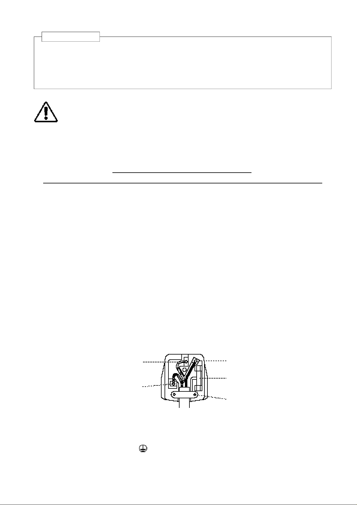
IMPORTANT:
The wires in the mains lead are coloured in accordance with the following code:
Green and Yellow = Earth, Blue = Neutral, Brown = Live.
Green & Yellow to Earth
Blue to Neutral
As these colours may not correspond with the coloured makings identifying the terminals in your plug, proceed
as follows:
The wire which is coloured Green and Yellow must be connected to the terminal in the plug which is marked
with the letter E or by the earth symbol or coloured Green or Green and Yellow.
The wire coloured Blue must be connected to the terminal marked with the letter N or coloured BLUE or
BLACK. The wire coloured BROWN must be connected to the terminal marked with the letter L or coloured
BROWN or RED.
Brown to Live
Fuse
Cord Clamp
Page 3
<Before Using>
About the Symbols Various symbols are used in this instruction manual and on the product itself to
ensure correct usage, to prevent danger to the user and others, and to prevent
property damage. The meanings of these symbols are described below. It is
important that you read these descriptions thoroughly and fully understand the
contents.
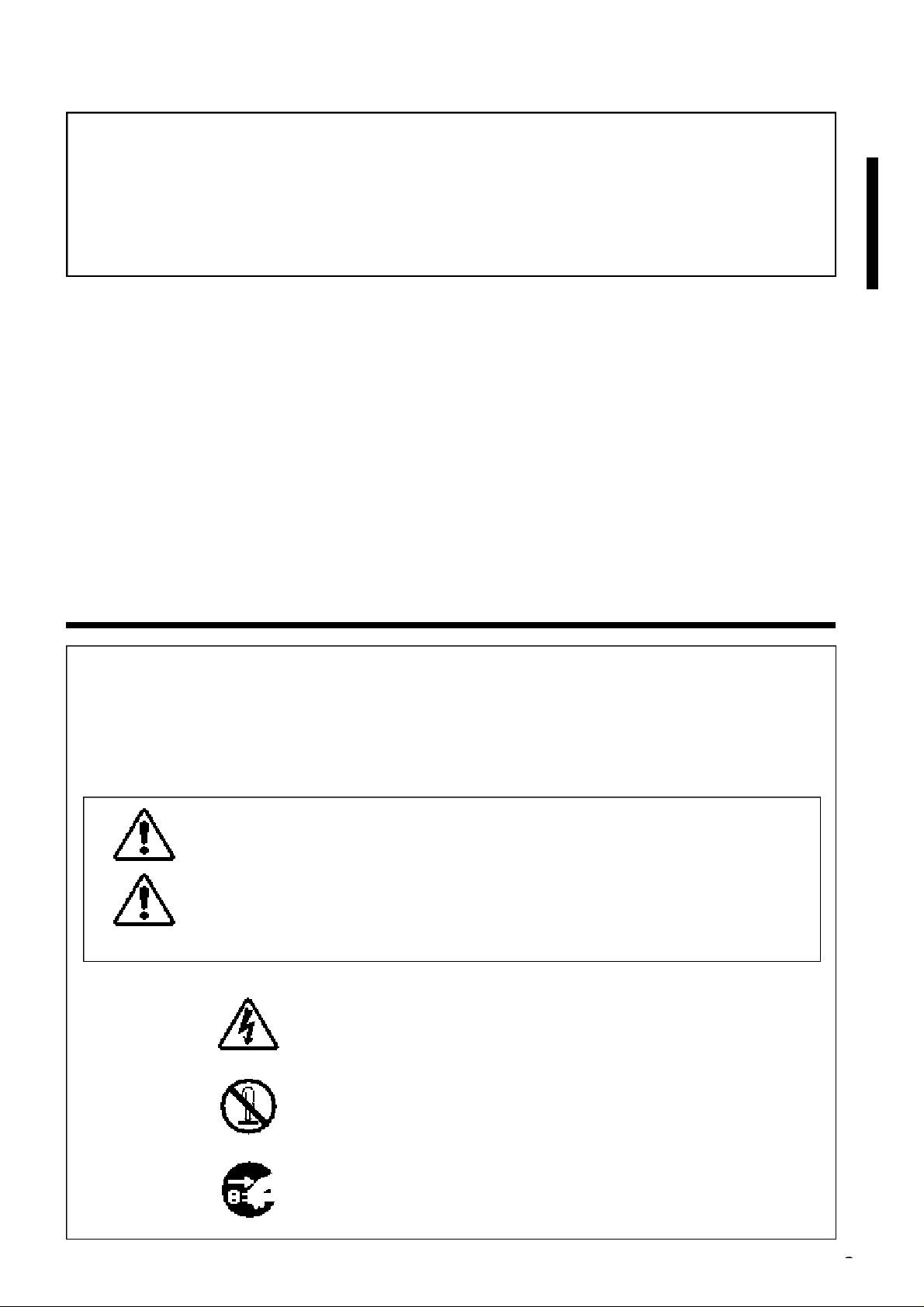
Warning
This symbol indicates information that, if ignored, could possibly
result in personal injury or even death due to incorrect handling.
Caution
This symbol indicates information that, if ignored, could result
possibly in personal injury or physical damage due to incorrect
handling.
Typical Symbols
This symbol indicates an additional warning (including cautions). An
illustration is provided to clarify the contents (the illustration to the left
indicates danger of electrical shock).
This symbol indicates a prohibited action. The contents will be clearly
indicated in an illustration or nearby (the symbol to the left indicates that
disassembly is prohibited).
This symbol indicates a compulsory action. The contents will be clearly
indicated in an illustration or nearby (the symbol to the left indicates that
the power plug should be disconnected from the power outlet).
WARNING: This equipment has been tested and found to comply with the limits for a Class A digital
device, pursuant to Part 15 of the FCC Rules. These limits are designed to provide reasonable protection
against harmful interference when the equipment is operated in a commercial environment. This equipment
generates, uses, and can radiate radio frequency energy and, if not installed and used in accordance with the
instruction manual, may cause harmful interference to radio communications, Operation of this equipment in
a residential area is likely to cause harmful interference in which case the user will be required to correct the
interference at his own expense.
Instructions to Users:
This equipment complies with the requirements of FCC (Federal Communication Commission) Class A
equipments provided that following conditions are met.
(1) Video signal cables:
Double shielded coaxial cables (so called FCC shield cable) must be used and the outer shield must be
connected to the ground. Or, if normal coaxial cables are used, the cables must be enclosed in metal pipes
or similar way to reduce the interference noise radiation.
(2) Power cord:
Shielded power cord must be used. The outer shield must be connected to the ground.
(3) Video inputs:
The input signal amplitude must no exceed the specified level.
Before Use
Page 4
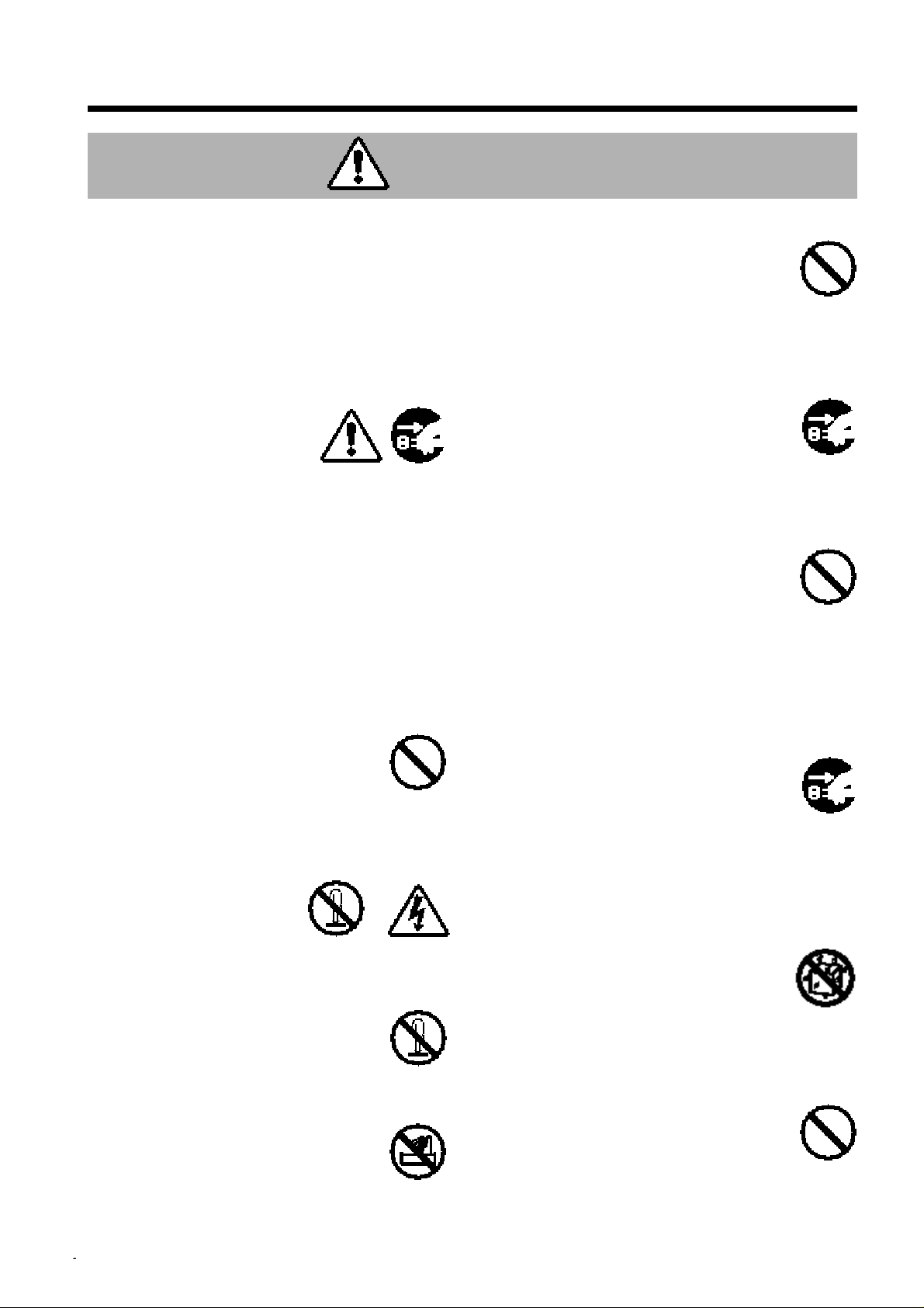
[Safety Precaution]
Warning
■ If a problem should occur.
If smoke or a strange odor arise, continued
•
use could result in fire or electrical shock. In
such case, immediately turn off the power
switch and then disconnect the power plug
from the power outlet. After making sure that
the smoke or odor has stopped, contact your
dealer for repairs. Never attempt to make
repairs yourself because this is dangerous.
Do not use this projector if
•
there is no image or
sound, or if the sound is
distorted. Continued use
could result in fire or
electrical shock.
In such case, immediately turn off the power
switch, disconnect the power plug from the
power outlet and contact your dealer.
If water should enter the inside of this
•
p r o j e c t o r, immediately turn off the power
switch, disconnect the power plug from the
power outlet and contact your dealer.
Disconnect the
plug from the
power outlet.
■ Do not install on an unstable surface.
Do not install this projector on an
•
unstable surface such as a wobbly
stand or incline because this could
result in the projector falling and
causing injury.
■ Do not open the cabinet.
Never open the cabinet.
•
There is high voltage
inside which can cause
electrical shock.
Contact your dealer for
internal inspection, adjustment and
repair.
Do not
disassemble.
Electric shock
hazard.
■ Do not modify.
Do not modify this projector because
this could result in fire or electrical shock.
Do not
disassemble.
■ Do not use in the bathroom.
Do not use this projector in the
bathroom because this could result in
fire or electrical shock.
Do not use near
water.
■ Do not insert foreign objects.
Do not insert metal objects through
•
the ventilation openings, etc., of
this projector or drop such objects
inside because this could result in
fire or electrical shock.
If a foreign object should enter this
•
p ro j e c t o r, immediately turn off the po w e r
sw i t ch, disconnect the
p ower plug from the
p ower outlet and contact
your dealer.
Continued use could result in
fire or electrical shock. Use
special caution in households
where children are present.
Disconnect the
plug from the
power outlet.
■ Do not look through the lens
when the lamp is on.
Never look through the lens when the
lamp is on. The powerful light could adversely
affect vision. Use special caution in households
where children are present.
■ Avoid shock or impact on the pro j e c t o r.
If the projector should fall,
resulting in damage to the
cabinet, immediately turn off
the power switch, disconnect
the power plug from the power
outlet and contact your dealer.
Continued use could result in
fire or electrical shock.
Disconnect the
plug from the
power outlet.
■ Do not place this projector in
a container containing liquid.
Do not place flower vases, flow e r
pots, cups, cosmetics, liquids
s u ch as water, etc., on top of this pro j e c t o r.
Spillage could result in fire or electrical shock.
■ Use only the indicated power
supply.
Use only the indicated pow e r
s u p p ly. The use of any other power supply
could result in fire or electrical shock.
Page 5
Warning
■ Handle the power cord with care.
Do not damage, cut, process or
•
s t ro n g ly twist the power cord. P l a c i n g
heavy objects on the power cord, heating or
strongly pulling the power cord can result in
damage as well as fire or electrical shock.
• Pulling on the power cord
• Placing heavy objects on the power cord
• Damaging the cord
• Placing near heaters
Do not position the pow e r
•
c o rd under the pro j e c t o r. This can
damage the power cord and cause fire or
electrical shock. Also, do not place a spread,
c o v e r, etc., over the power cord because this
could result in the inadvertent placing of
heavy objects on the concealed power cord.
If the power cord is damaged
•
(exposed or broken core wires,
etc.), contact your dealer for
replacement; otherwise, fire or
electrical shock could result.
Make sure there is no dust, etc., on the power
•
plug and insert a knife blade to make sure that
there is no looseness.
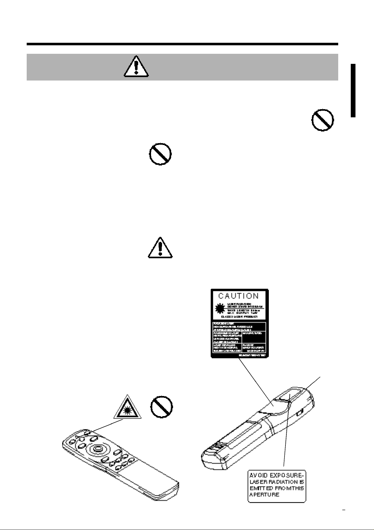
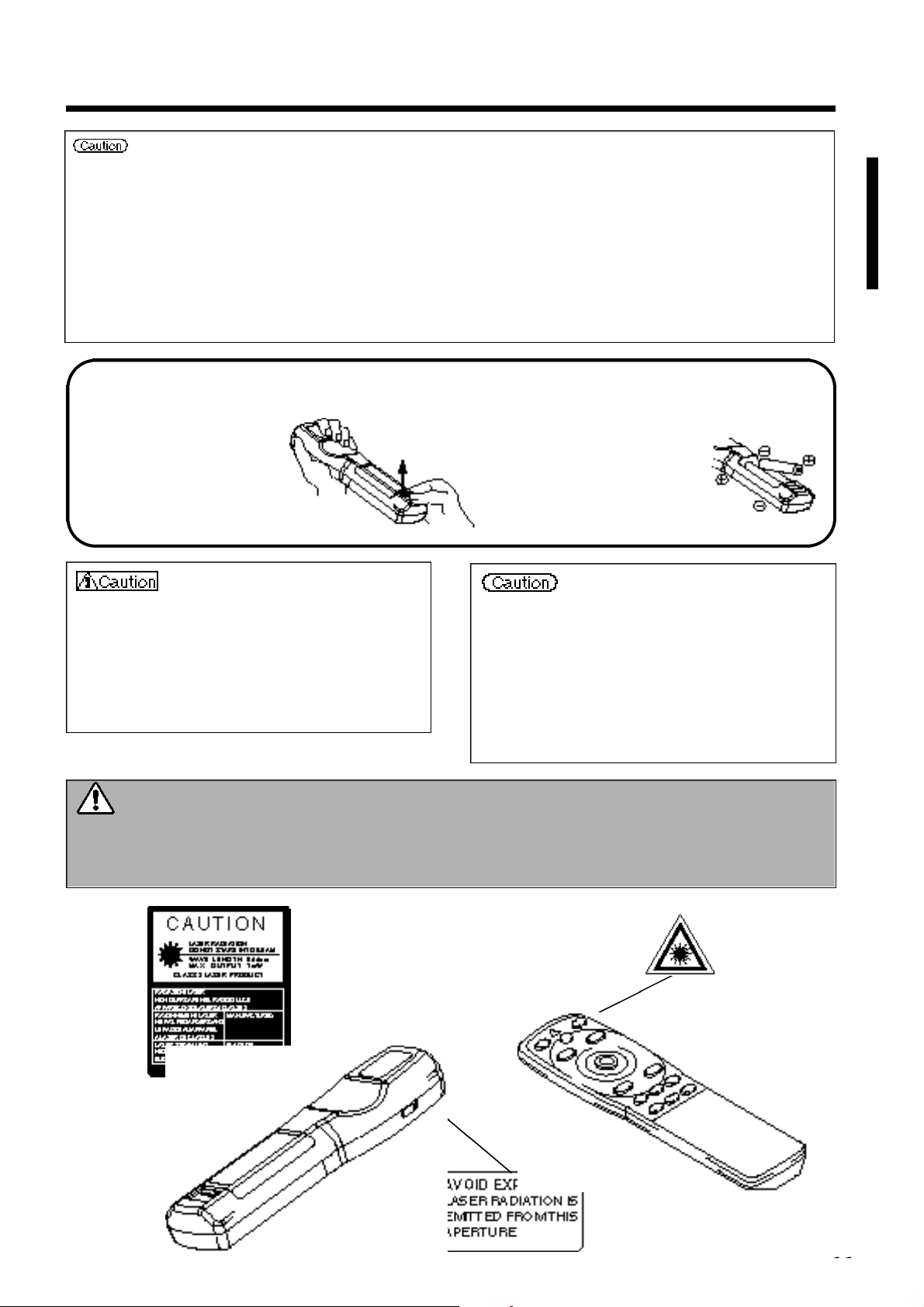
■ Do not allow the laser beam to enter the
eye s .
This remote control is equipped with a
•
laser pointer and a laser beam is emitted
from the laser outlet. Do not look directly
into the laser beam outlet or direct the
laser beam at other people.
Vision can be impaired if the laser beam
enters the eyes. Use special caution
where children are present.
■ High temperatures are generated when
the lamp is lit, so do not place objects in
f ront of the lens.
Laser beam outlet
Page 6
■ Do not sit or place heavy objects on
this projector.
•
Do not sit on this projector.
This could result in overturning,
leading to damage or personal injury.
Use special caution in households
where children are present.
•
Do not place heavy objects on this
projector.
Placing heavy objects on this projector
could result in loss of balance or falling
and cause personal injury.
■ Do not bl o ck the ventilation openings.
Do not block the ventilation openings of
this projector. Blocking ventilation could lead
to internal overheating which could result in
fire. Do not place this projector on its
side during use or push it into a small,
poorly ventilated location. Do not
place this projector on a carpet or
bedding or cover it with a table cloth,
etc. Also, when installing this projector, make
sure the ventilation openings are at least 30cm
from the wall.
■ Care and maintenance.
For safety purposes, disconnect the power
plug from the power outlet
before starting the care and
maintenance of this projector.
■ Battery usage.
•
Use only the specified batteries with
this pro j e c t o r. Do not mix old
and new batteries because this
could result in fire or personal
injury due to battery cracking or
leakage.
•
Make sure the plus and min u s
terminals are correctly aligned
when loading the batteries.
Incorrect loading could result in
personal injury or contamination of
the surroundings due to battery cracking or
leakage.
■ Clean the projector interior once
every two years.
Request your dealer to clean the interior
of the projector approximately every two
ye a rs . Accumulations of dust inside the
projector can result in fire or
malfunction if not cleaned for an
extended period. This cleaning is
more effective if performed befor
every humid periods such as rainy
season, etc. Ask your dealer for details about
internal cleaning.
■ Avoid installation in humid or dusty
locations.
•
Do not install this projector in a humid
or dusty location. This could
result in fire or electrical shock.
•
Avoid installation near the
kitchen, a humidifier or other locations
where there is oily smoke or humidity.
This could result in fire or electrical shock.
■ Use the caster brakes.
When installing this projector on a stand
with casters, use the caster
brakes to prevent the stand
m oving or ov e rturning and
causing personal injury.
■ Do not handle the power cord r o u g h ly.
•
Keep the power cord aw ay fro m
h e a t e rs because the heat could melt the
power cord and cause fire or electrical shock.
•
Do not touch the power plug
with wet hands because this
could result in electrical shock.
•
When disconnecting the
p ower plug, do not pull on the pow e r
cord. This could damage the power cord and
cause fire or electrical shock. Always grip the
plug when disconnecting.
Caution
Disconnect the
plug from the
power outlet.
Page 7
■ Avoid excessively hot locations.
Do not place this projector in direct
sunlight or near a hot object such as a
stove, etc., because the heat could
have adverse influence on the cabinet
and other parts.
■ Sound volume.
Set the volume at a suitable level to avoid
bothering other people. It is also better to keep
the volume level low and close the windows at
night to protect the neighborhood environment.
■ Lens care
Use commercially available lens
tissue to clean the lens (used to clean
cameras, eyeglasses, etc.). Be careful
not to scratch the lens with hard
objects.
■ Cabinet care.
•
The cabinet is made of plastic and discoloration
or paint peeling can occur if wiped with a solvent
such as benzine, thinner, etc.
•
Before using chemical wipes, be sure to read
and observe the instructions.
•
Do not spray volatile substances such as
insect repellent on the cabinet. Also, do not
allow long-term close contact with rubber or
vinyl products because this could result in
discoloration, peeling paint, etc.
•
Use a soft cloth to clean the cabinet and
operation panel. When excessively soiled,
dilute a neutral detergent in water, wet and
wring out the cloth and afterward wipe with a
dry cloth. Do not apply undiluted deterg e n t
directly to the projector.
■ Extended usage.
When using this projector for an extended
period, stop periodically to rest the eyes to
prevent eye fatigue.
Caution
■ When the projector is not to be used
for an extended period.
For safety purposes when the
projector is not to be used for an
extended period because of travel,
etc., always disconnect the power
plug from the power outlet. Also
close the lens cover to prevent the lens
surface being scratched.
Disconnect the
plug from the
power outlet.
[General Cautions]
■ Moving the projector.
When moving the projector, be sure
•
to replace lens cap, disconnect the
power plug from the power outlet
and disconnect all external
connections. Failure to do this
could damage the power cord
and cause fire or electrical shock.
Avoid any impact or shock to the projector
because this could result in malfunction.
When moving this projector outdoors, protect
•
it from wetting due to rain, etc. If the
projector should become wet, dry it
thoroughly before further use.
Continued use while wet could
result in fire or electrical shock.
Disconnect the
plug from the
power outlet.
Page 8
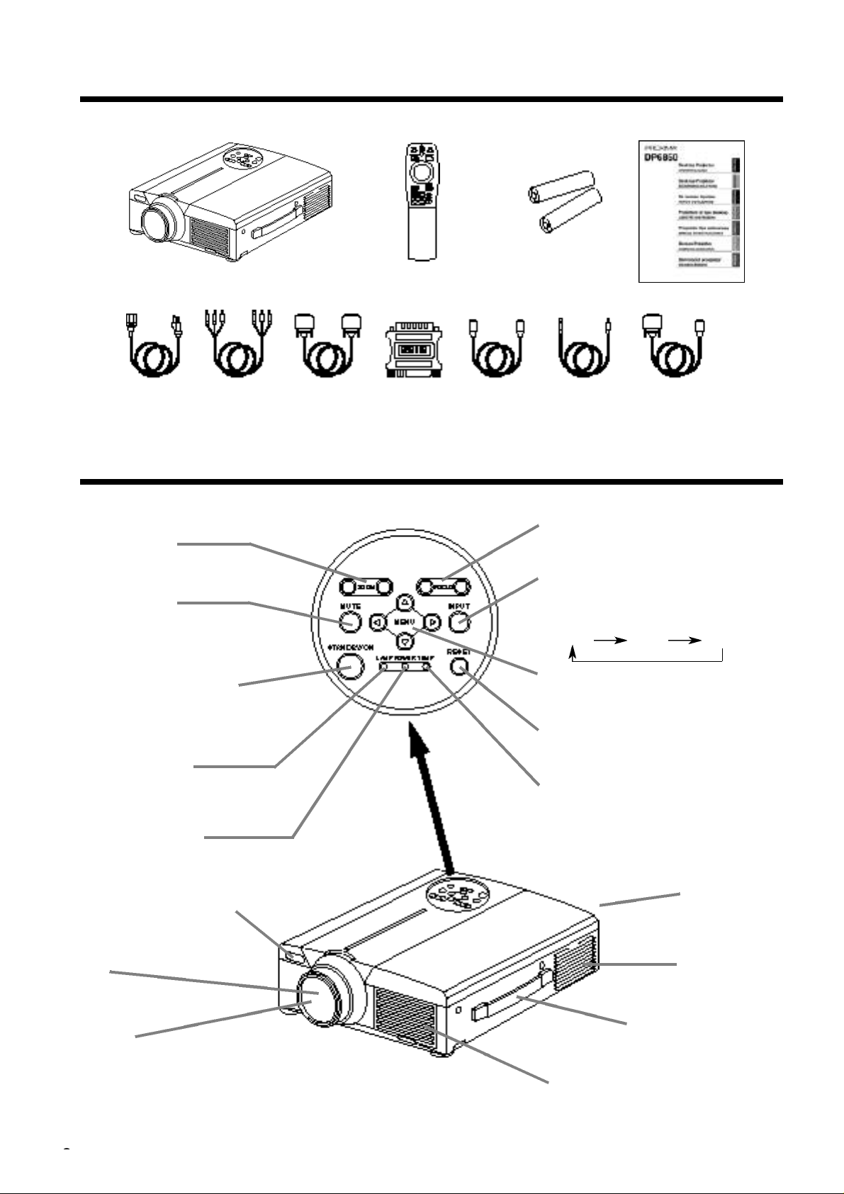
Checking the package Contents
Make sure all of the following items are included in the package. If anything is missing, please contact your
dealer.
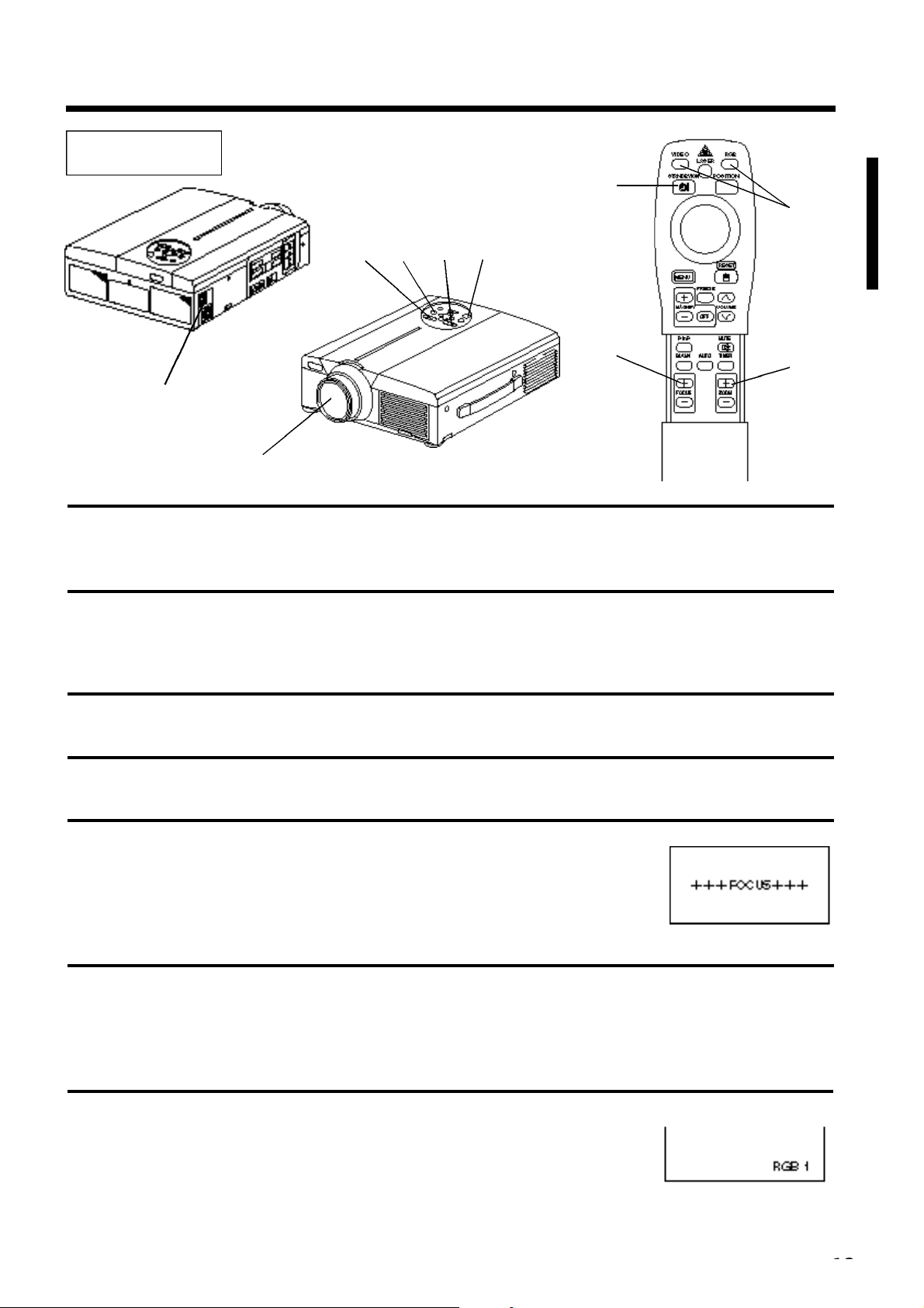
• Use the remote control in front of the remote control photoreceptor at a distance
of about 5 m or less and an angle of 30 degrees to the left or right of the center.
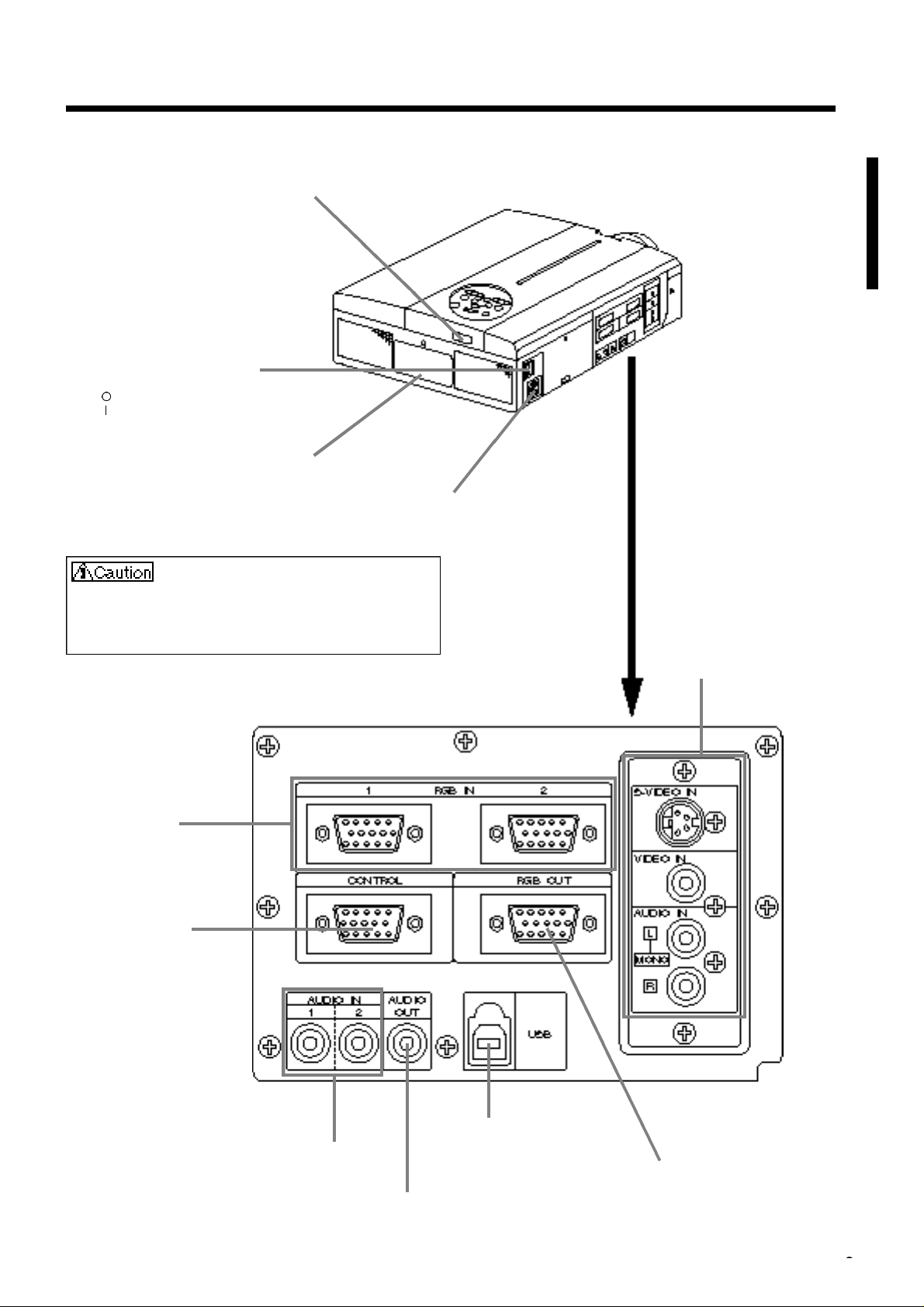
Main unit
STANDBY / ON button
Press this button to turn the power on
and off. When turned off, the projector
enters standby status. Refer to page 13
- 14 for details.
MUTE button
This button turns the sound on and
off. Press once to turn the sound off;
then press again to turn the sound
back on.
ZOOM button
Used to adjust the size of the
image. (Refer to page 13.)
POWER indicator
This indicator lights or blinks during standby
and during operation. Refer to page 33 for
details.
TEMP indicator
Blinks when the fan malfunctions.
Refer to page 33 for details.
Remote control I/R receiver
Lens
Lens cap
Speaker
Cooling fan
(intake side)
Cooling fan
(exhaust side)
Carring handle
Remote control
Projector unit Remote control
Batteries
User’s Guide (this document)
Power Cord × 3
110V-US
220-UK, Europe
3 - C o n d u c t o r
Video/Audio Cable
RGB Cable
(15-15 pin M/M)
Mac adapter
with dip switch
S-Video Cable
(S-Video mini Din4-pin)
Stereo mini jack
c a b l e
Names and functions of each part
FOCUS button
Used to adjust the focus of the image on the
LAMP indicator
Lights or flashes when the temperature
inside the projector increases or the lamp
does not light. Refer to page 33 for details.
screen. (Refer to page 13.)
INPUT button
Press this button to switch the input. The input
changes in the following sequence each time
this button is pressed.
RGB1 RGB2 VIDEO
MENU button
Displays the image menu. Refer to page 17 21 for details.
RESET button
Used to reset the initial settings.
Refer to page 10, 17, 25, 26 for details.
Mouse cable × 3
Speaker
Page 9
Names and functions of each part (continued)
Remote control I/R receiver
Main power switch
Used to turn the power on and off.
: OFF
: ON
Security slot
Use with
kensington lock
AC IN jack
Used to connect the
accessory power cord.
Connecting to the AC IN jack
Make sure the accesory power cord is plugged into
the AC IN jack as far as it will go. Incomplete
connection can result in fire or electrical shock.
RGB IN jack
D-sub 15-pin shrink (1/2)
CONTROL jack
D-sub 15-pin shrink
VIDEO IN jack
S-VIDEO IN jack
Mini DIN 4-pin connector
VIDEO IN jack
RCA jack
AUDIO L/R IN jack
RCA jack
AUDIO IN jack (RGB)
Stereo mini jack
AUDIO OUT jack (RGB/VIDEO)
Stereo mini jack
USB jack
The mouse cursor can be controlled by
remote control by connecting to a
personal computer.
RGB OUT jack
D-sub 15-pin shrink
Page 10
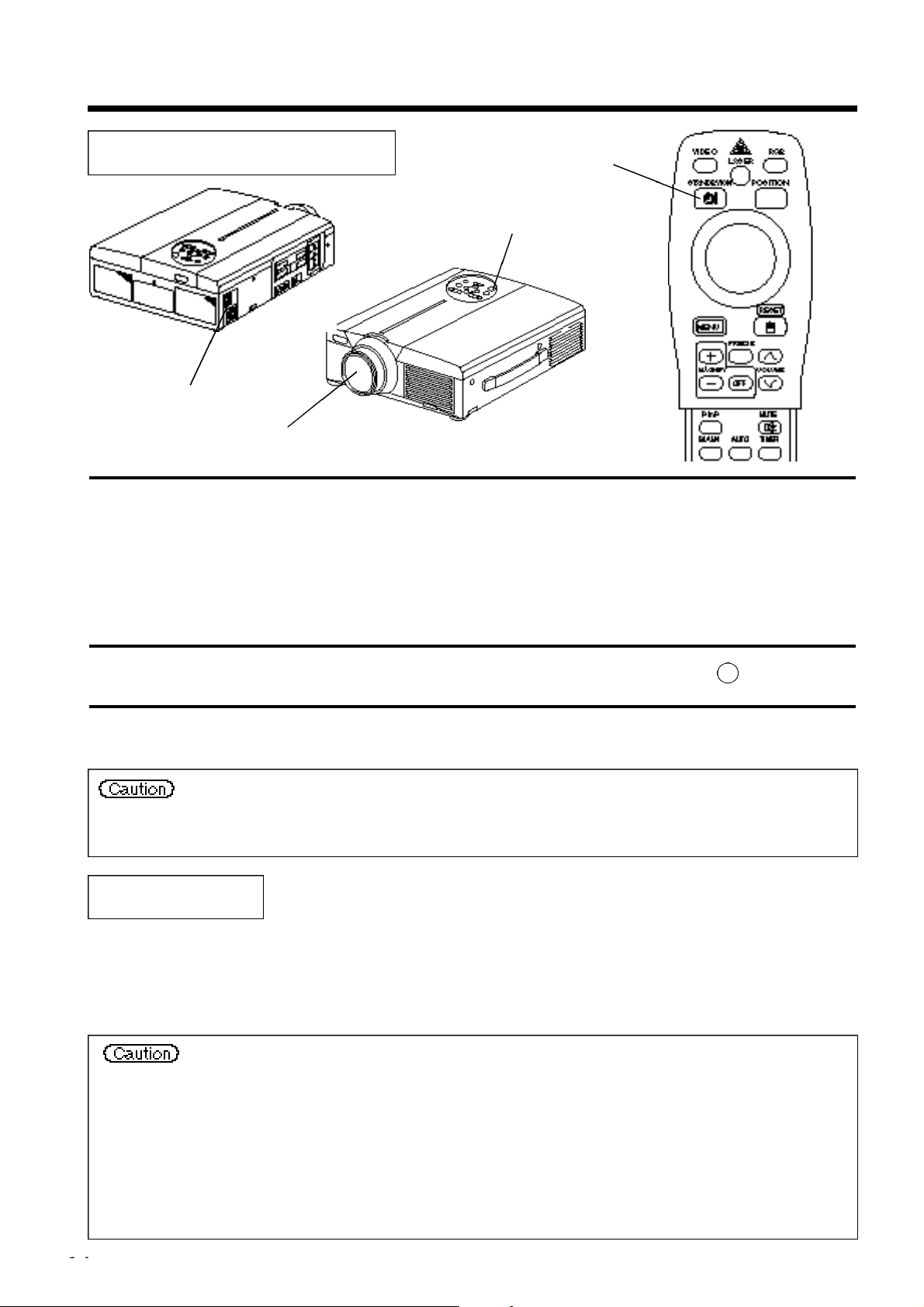
Names and functions of each part (continued)
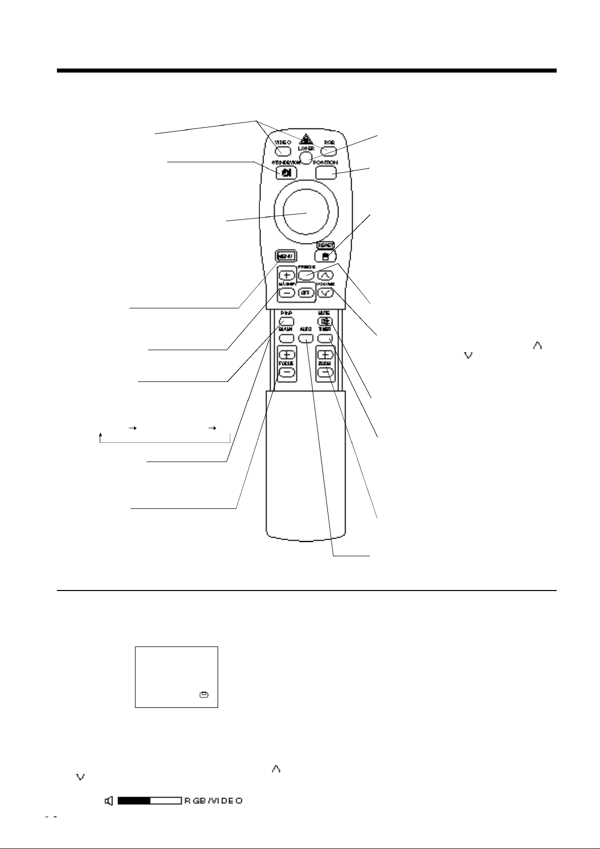
Remote control transmitter
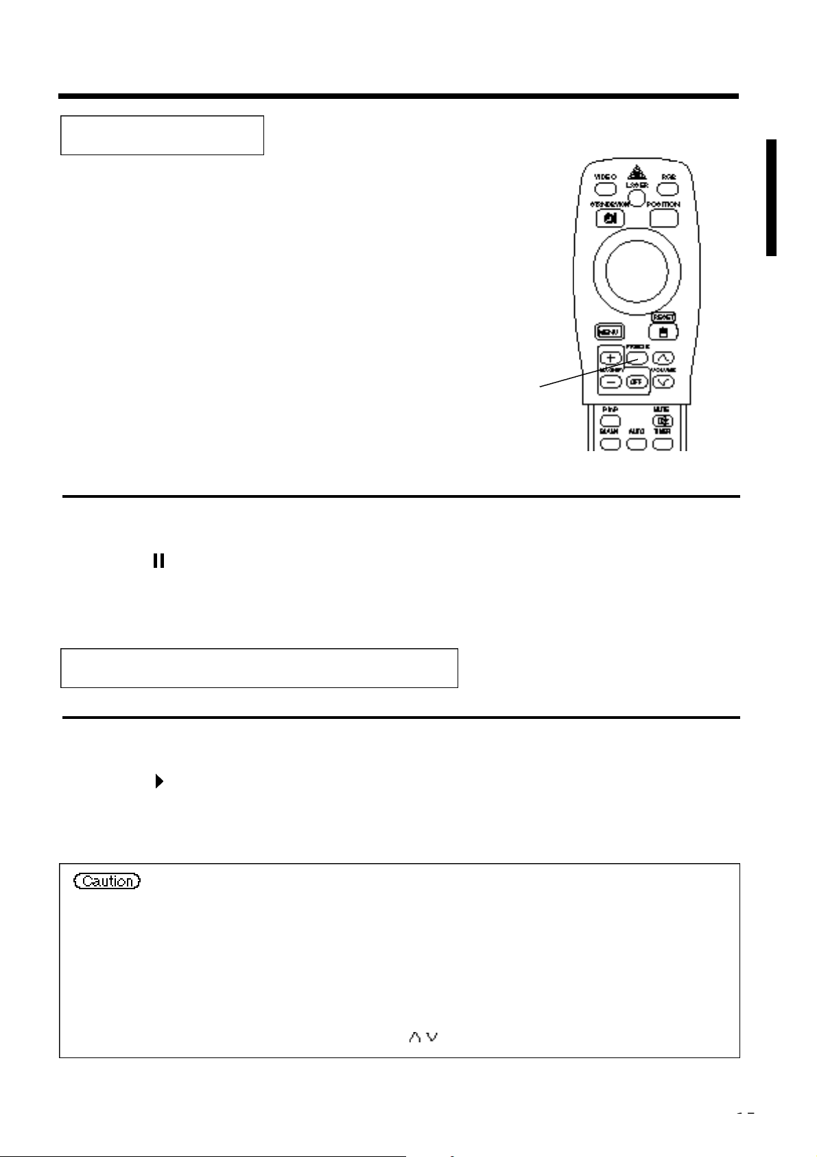
FOCUS button
Used to adjust the focus of the image on the
screen. (Refer to page 13.)
ZOOM button
Used to adjust the size of the image. (Refer to
page 13.)
FREEZE button
Used to turn the freeze (still) image display on and off.
(Refer to page 15).
AUTO button
Used to execute auto-adjust.
*3
*
These functions do not operate when initial screen message “NO INPUT IS DETECTED” or “SYNC IS OUT OF RANGE” is displayed.
MAGNIFY button
Used to magnify the displayed image.
(Refer to page 16).
BLANK button
Used to turn blanking on and off.
(Refer to page 20.)
*2
P in P function
With the P in P function, signals are input to both RGB and
VIDEO. This function operates only when the RGB signal has
been selected. There is no display in the case of the no signal and
when the RGB signal is outside the sync range.
When P in P is used, audio is automatically switched to video.
In P in P, audio input can be switched by pressing the VOL and
VOL keys of the remote control, displaying the audio bar and
moving DISK PAD left and right during the display.
VIDEO, RGB button
Press to switch the input. (Refer to page 13, 19.)
STANDBY / ON button
Used to turn the power on and off.
Press for 1 sec. or more to turn the power off
(enter standby status).
(Refer to pages13 and 14.)
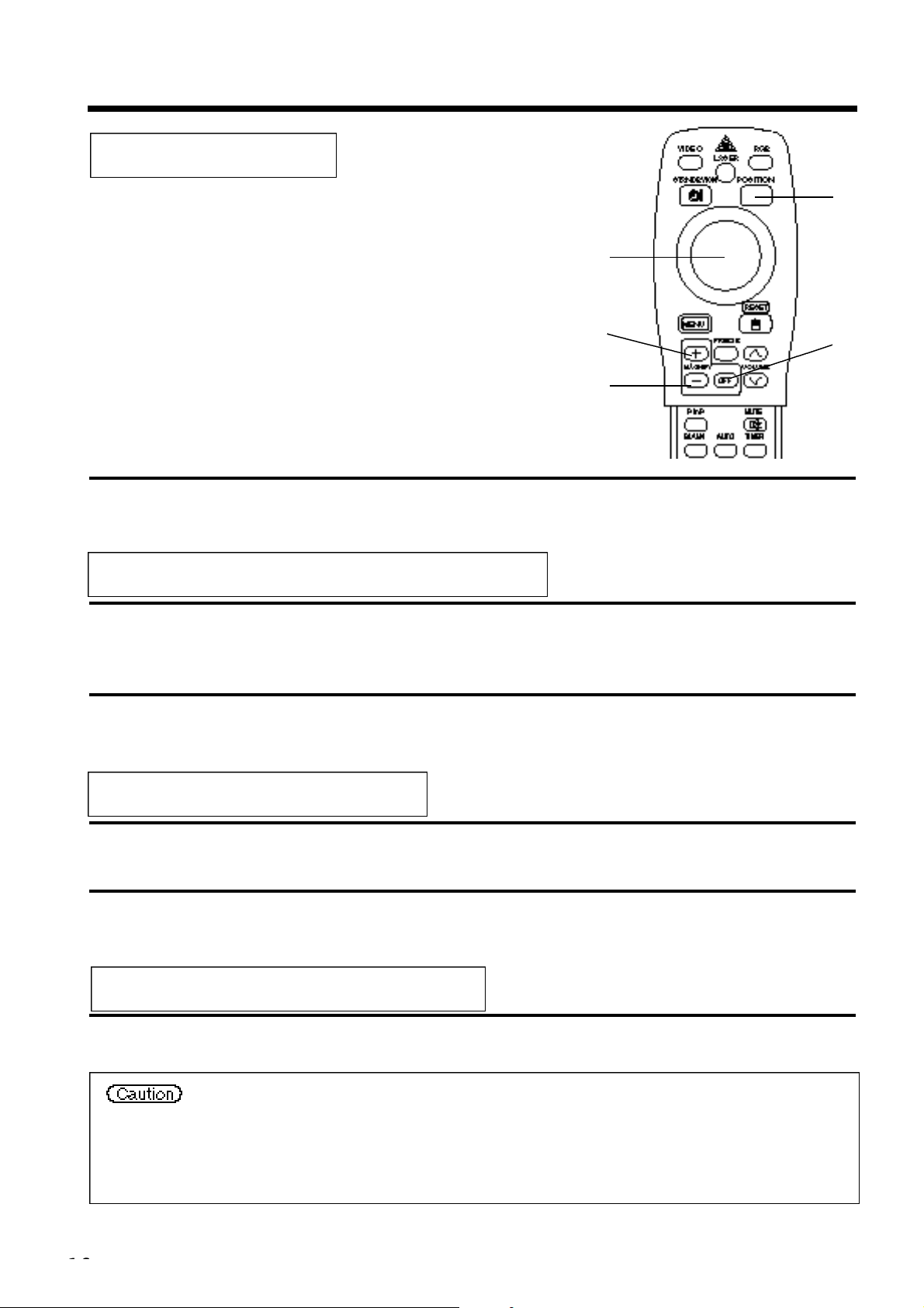
DISK PAD / MOUSE LEFT button
*
(1) Used to select menu items when the menu
screen is displayed (refer to page 16 - 18).
(2) When the menu is not displayed, the
computer mouse shift function and left click
function are active.
(3) After the POSITION button has been
*1
pressed, the screen can be moved upward,
downward and to the left and right.
MENU button
*
Used to turn the menu screen display on and off.
(Refer to page 17 - 21).
*
P in P button
*
Used to turn P in P (Picture In Picture: displays sub video
signal images in the RGB signal) on and off.
Each time this button is pressed, operation will change in
the following sequence:
(1) Small sub screen (2) Large sub screen (3)Off.
(1) ∼ ( 3 )
(Refer to page 20).
*2
*4
LASER button
Turns the laser beam on and off. Refer to page
11 concerning usage and observe the cautions.
POSITION button
*
Press Position, then use the mouse Disk Pad to adjust
the image position (RGB mode only)
(Refer to page 16).
RESET / MOUSE RIGHT button
*
(1)Operates as the RESET button when the menu
is displayed. Press this button to return to the
initial settings.
(2)Used to click the right mouse button when the
menu is not displayed (refer to page 25,26).
(3)Pressing this button after scrolling the screen
*1
with POSITION returns the screen to the original
position.
*
VOLUME button
Adjusts the volume of the sound. Press [ ] to
increase the volume and ( ) to decrease the volume.
When there is no video signal input, operation is not
possible when the input video signal is outside the
sync range.
MUTE button
*
Applies Mute. (Press the Play button again to
cancel.)
TIMER button
Turns the display of the time set with the Timer
on the Menu screen on and off.
The timer is not displayed when no input signal
is detected or when SYNC is out of range or
during blanking or during freezing.
Refer to page 21 concerning the method used to
set the timer.
*
*1
POSITION icon
When the POSITION button is pressed, the moving display icon
will appear at the bottom right of the screen.
While displaying the icon, you can operate POSITION.
*3
The projector automatically adjusts 4 items (V. POSIT, H. POSIT,
H. PHASE, H. SIZE).
When you choose AUTO (move the cursor to the right from the
manual operation position), the AUTO confirmation menu shown
below is indicated.
*4
Auto adjustment function
Disk Pad method of operation
• Move and select by tilting Disk Pad in the required direction.
• Press Disk Pad in to realize the function of the mouse left
button.
• A mouse cable is necessary if a mouse is to be used.
(Refer to pages 26, 27.)
Page 11
Names and functions of each part (continued)
Loading the batteries Loading AA batteries into the remote control.
The laser pointer of the remote control is used as a pointer.
N ever look directly into the laser beam outlet or point the laser beam at
other people.
The laser beam can cause vision problems.
• Auto adjust can take up to 30 seconds.
• Auto adjust may not operate correctly in some cases, depending on the computer connected and the signal.
• Be sure to expand images to full screen size when displaying low resolution images.
• After auto adjust, the image may be slightly dark in some cases due to automatic adjustment of the signal level.
• Auto adjust can not execute when the initial display is “NO INPUT IS DETECTED” or “SYNC IS OUT OF RANGE”
during FREEZE or MAGNIFY.
• Auto Adjust is executed when the following operations are performed.
1. When the type of input source signal is changed.
2. When the Auto Adjust (AUTO) button is pressed.
• The message AUTO IN PROGRESS will be displayed on the screen during automatic adjustment.
• The screen may be disrupted during automatic adjustment but this is not a malfunction.
• RGB1 or RGB2 only can be used as the input signal.
• Auto Adjust can also be executed using the operation buttons of the main unit. Hold down the RESET button and press
the input switch (INPUT) button.
1R e m ove the battery
cover.
Push the knob while
lifting up the battery
cover.
2Loading the batteries.
Make sure the plus and
minus poles are correctly
o r i e n t e d .
3Close the battery cover.
Battery usage cautions
Use only the specified batteries with this projector. Also, do
•
not mix new and old batteries. This could cause in battery
cracking or leakage, which could result in fire or personal
injury.
When loading the batteries, make sure the plus and minus
•
poles are correctly oriented as indicated in the projector.
Incorrect orientation could cause battery cracking or
leakage, which could result in personal injury or pollution
of the surrounding environment.
Do not drop the remote control or apply impact.
•
Do not wet the remote control or place it on any wet object.
•
Such actions could result in malfunction.
When not to be used for an extended period, remove the
•
batteries from the remote control.
Replace the batteries when remote control operation
•
becomes difficult.
Do not place the remote control close to the cooling fan of
•
the projector.
Do not disassemble the remote control in case of
•
malfunction. please bring it to the service station.
Warning
Remote control usage cautions
Page 12
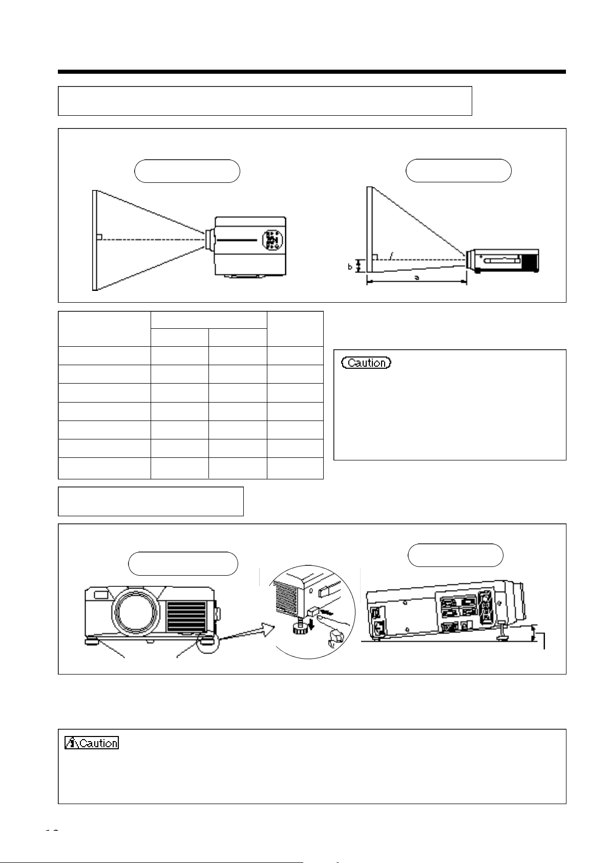
Installation
Typical LCD Projector and Screen Installation
Using the adjusters
a. Distance from the LCD projector to the screen
b.Distance from the lens center to the bottom of
the screen (a,b : +/-10%).
The projection distances shown in the diagram to
the left are for full size (1,024 x 768 dots).
The LCD projector should normally be used
level (the legs can point upward).
Positioning the projector sideways, or with the
lens pointing upward or downward can cause the
internal temperature to rise, which could result in
a malfunction.
Use the diagram below as reference to determine the screen size and projection distnace.
Screen
Top view
Diagonal screen size (inches)
40 55 73 1
60 85 114 2
80 114 151 2
100 144 191 3
120 176 231 3
150 220 282 4
200 291 386 6
Minimum a Maximum
Side view
Lens center
a (inches)
b (inches)
Use the adjusters on the bottom to adjust the projection angle.
Front view
Adjuster
1. Lift up the projector and release the adjuster lock.
2. After adjusting the projection angle, firmly lock the adjusters.
3. Rotate the adjusters for fine adjustment.
• Do not release the locks unless the projector is being held; otherwise, the projector could
overturn or the fingers could get caught and cause personal injury.
• Do not force the adjusters to rotate. This could damage the adjusters or cause the lock to fail.
• Lock the adjusters firmly. If the lock is difficult to operate, change the angle slightly and try again.
Side view
Variable within the range of approximately 0° - 9°
Page 13
Basic operations
To project
2
4
5
7
1
2
4
2
1
5
7
3
Turn on the main power switch of the projector [ I: ON].
• The Power indicator lights orange.
Press the STANDBY / ON button.
• The Power indicator will blink green and then light green.
• The green blinking indicates warmup.
3
4
5
6
7
Remove the lens cap.
Use the ZOOM button to adjust the screen size.
Use the FOCUS button to adjust the focus.
(1) The display shown to the right will appear when the FOCUS button is pressed.
(2) Use the FOCUS button to adjust the focus until the image is sharp.
(3) The message “Focus” will disappear if any other button is pressed.
• (
When there is no input signal, the Focus characters are not displayed when the input signal is outside the sync range.)
Turn on the power to the connected equipment.
Refer to page 31 concerning the connection of other equipment.
Press either the INPUT button of the
p rojector or the VIDEO/RGB button of the
remote control to select the signal to be
projected on the screen.
The selected signal input channel will be displayed in the lower right part of the screen.
Example on-screen display
Page 14
Basic operations (continued)
Turning off the power
2
3
1
Press the STANDBY/ON button for approximately 1 sec.
• The Power indicator will blink orange, then the lamp will turn off. Approximately 1 sec. after that, the
indicator will light orange.
• After the power is turned off, the lamp will be cooled for approximately 1 min. and the power cannot
be turned off even by pressing the STANDBY/ON button.
• Prese the STANDBY/ON button for at least 3 seconds to power off.
1
1
2
Turn off the main power switch of the projector [ : OFF].
3
Attach the lens cap.
The fan will continue running for approximately 1 min. after the STANDBY/ON button is pressed.
Do not turn off the main power switch while the lamp is on because this will shorten the service life of
the lamp.
Plug & Play
This projector is VESA DDC 1 and DDC 2B compatible. Plug & play is possible by connecting to a computer
that is VESA DDC (Display Data Channel) compatible to RGB 1.
(Plug & play is a system configured with peripheral equipment including a computer and display, and an
operating system.
• Use the RGB cable included with this projector when using plug & play. With other cables,
pins (12) - (15) are sometimes not connected (effective only for RGB1).
• This device is recognized as a plug-and-play monitor. Use the standard Windows95/98 display
drivers.
• This function may not operate, depending on the personal computer used.
• When the DDC function does not operate on a personal computer running Wi n d o w s 9 5 / 9 8 ,
select the display type from Screen Priority. It is recommended that Super VGA 1024 x 768
(60-75Hz) be selected as the display type.
The DDC function will not operate when connected to a Macintosh.
Page 15
Basic operations (continued)
Freeze function
This function is used to freeze the image being displayed.
(refer to page 10)
1
1
• The image being displayed will freeze.
• The [ ] mark appears in the lower right corner of the screen when the Freeze function is on.
Cancelling the FREEZE function
Press the FREEZE button.
1
Press the FREEZE button.
• The FREEZE function will be cancelled.
• The [ ] mark will be displayed for approximately 3 sec. when the FREEZE function is cancelled.
• When there is no input signal, the Freeze function is not effective when the input signal is
outside the sync range.
• Pressing the FREEZE button alternately turns the freeze function on and off.
• The FREEZE function will be cancelled when the input select button is pressed or the display
mode of the PC being used for display is changed.
• When a still image signal is input when the FREEZE function is on, make sure not to forget to
cancel the FREEZE function.
• FREEZE function will be cancelled after the operations such as “FOCUS +, –”, “TIMER”,
“P in P”, “AUTO”, “BLANK”, “VOLUME ”,“MENU”, “MUTE” and “POSITION”.
Page 16
1
Press the MAGNIFY+button.
• The center part of the image will be displayed magnified approximately 2x.
2
Press the MAGNIFY +bu t t o n .
• When this button is pressed, the image will be displayed even larger.
3
Press the MAGNIFY –button.
• When this button is pressed, the image will be displayed even smaller.
4
Press the POSITION button.
5
Press the DISK PAD up, down, left and right buttons.
• The magnified area will move in accordance with the button pressed.
6
Press the MAGNIFY OFF button.
Basic operations (continued)
Magnify function
Part of an image can be displayed magnified.
(refer to page 10)
5
1,2
3
Changing the magnification ratio
4
6
Moving the display area
Returning to normal display
• When there is no video signal input, Magnify is not effective when the video signal input is
outside the sync range.
• The magnify function will be cancelled when the input select button is pressed or the display
mode of the PC being used for display is changed.
• The Magnify function will be cancelled after the operations such as “AUTO”, “KEYSTO N E ” .
Page 17
Returning to the initial settings
Adjustments and functions
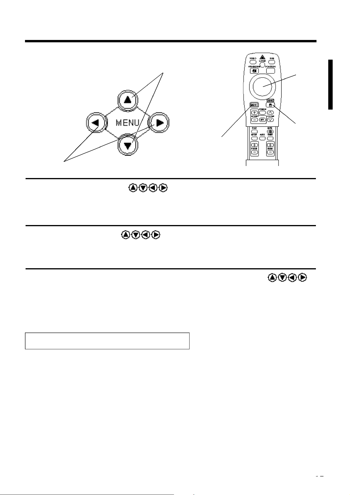
1
Press the MENU ( ) buttons of the projector or the
MENU button of the remote control.
• The Menu screen will appear. (refer to page 18 - 21 for details.)
2
Press the MENU ( ) buttons of the projector or the DISK
PAD button of the remote control to select the menu item to be
a d j u s t e d .
• The selected menu item will be displayed in orange.
3
Adjust the selected menu item with the MENU ( )
buttons of the projector or the DISK PAD button of the
remote control.
• The selected menu item will be displayed in orange.
• Select the adjustment item to be returned to the initial settings.
• Press the RESET button.
1,2,3
1,3
2,3
3
1
Page 18
Adjustments and functions (contin u e d )
RGB signal input
Video signal input
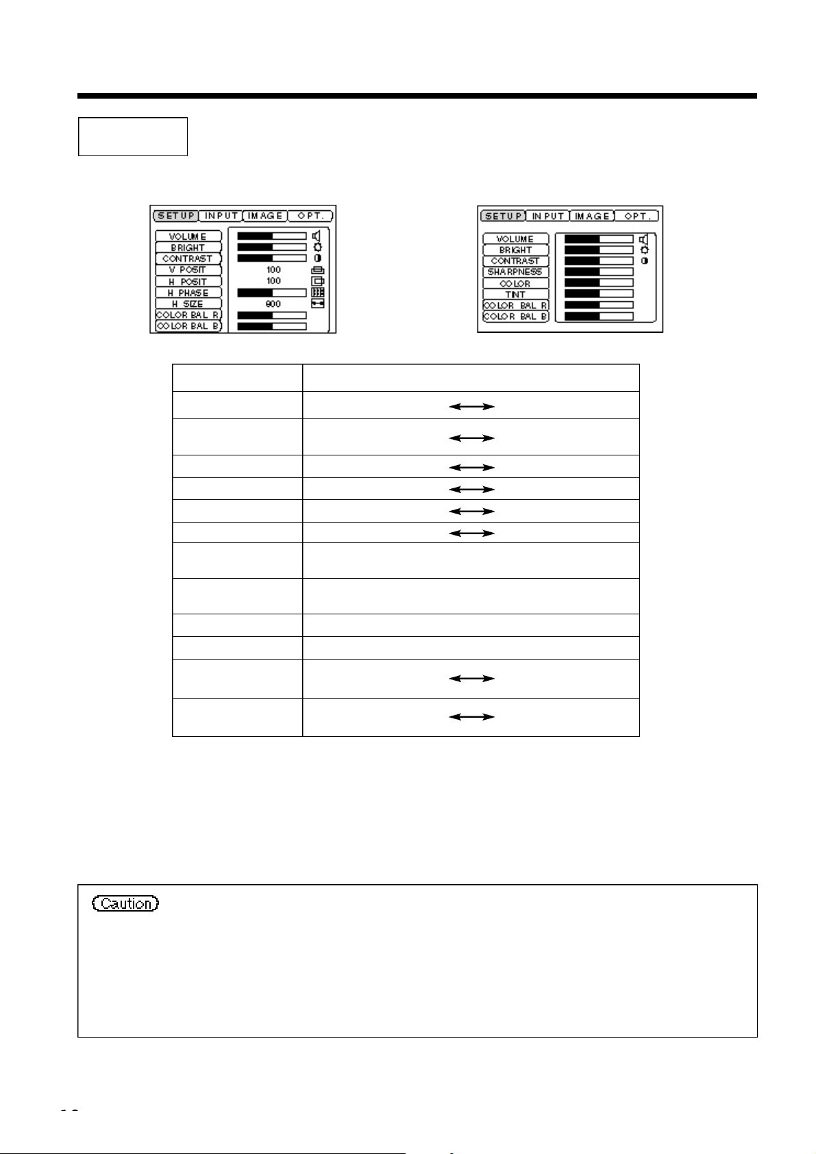
SET UP
Images and display positions can be adjusted from the SETUP menu.
Adjustment item
VOLUME
BRIGHT
(BRIGHTNESS)
CONTRAST
SHARPNESS
COLOR
TINT
V. POSIT
(V. POSITION)
H. POSIT
(H. POSITION)
H. PHASE
H. SIZE
COLOR BAL R
(COLOR BALANCE Red)
Adjustment description
Volume decreases Volume increases
Darker Brighter
Lower contrast Stronger contrast
Softer image Sharper image
Less More
Redder Greener
Moves the image up and down.
Moves the image left and right.
Eliminates blanking.
Adjusts the horizontal size of the image.
Less red More red
COLOR BAL B
(COLOR BALANCE Blue)
Less blue More blue
Using the SETUP Menu
Move the cursor to the item to be adjusted and move the MENU button of the projector or the DISK PA D
button of the remote control to change the length of the bar display.
• The menu cannot be displayed while the initial screen (“No input is detected.” or “Sync is
out of range.”) is being displayed.
• Tint cannot be adjusted with N-PAL, M-PAL, PAL or SECAM video signal input.
• Tint, color and sharpness cannot be adjusted with RGB signal input.
• V. POSIT, H. POSIT, H. PHASE and H. SIZE cannot be adjusted with video signal input.
• FREEZE function will be cancelled after the operation “Menu”.
• Displaying the menu cancels freeze operations.
Page 19
Adjustments and functions (contin u e d )
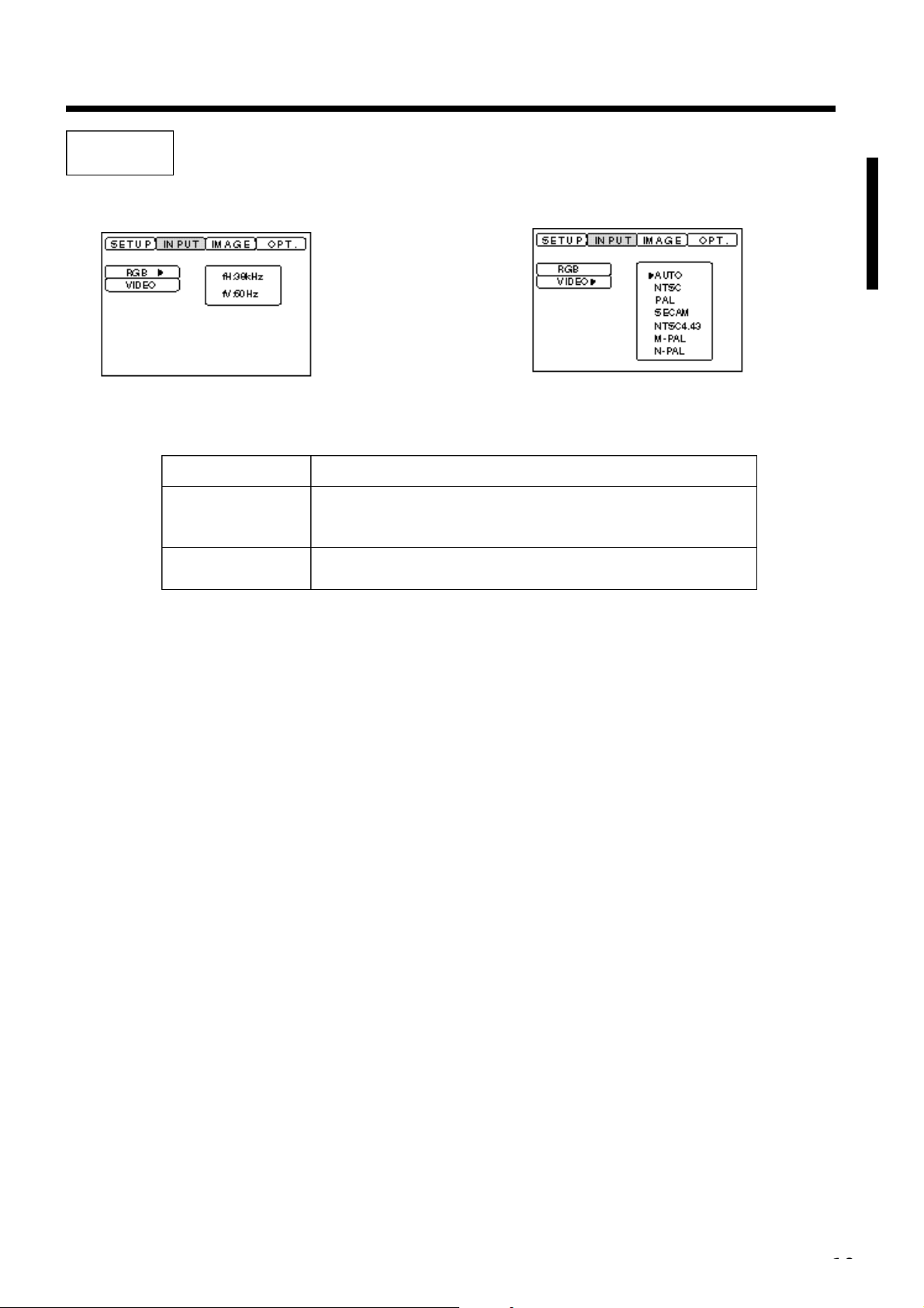
INPUT
The INPUT menu is used to select RGB signal sync signal frequency of the monitor and the VIDEO signal.
Adjustment item
RGB
VIDEO
Adjustment description
Displays the following RGB inputs
fH: horizontal sync frequency
fV: vertical sync frequency
Sets the video signal system. When the screen is unstable (no color)
or rolls, select the mode that matches the input signal.
Page 20
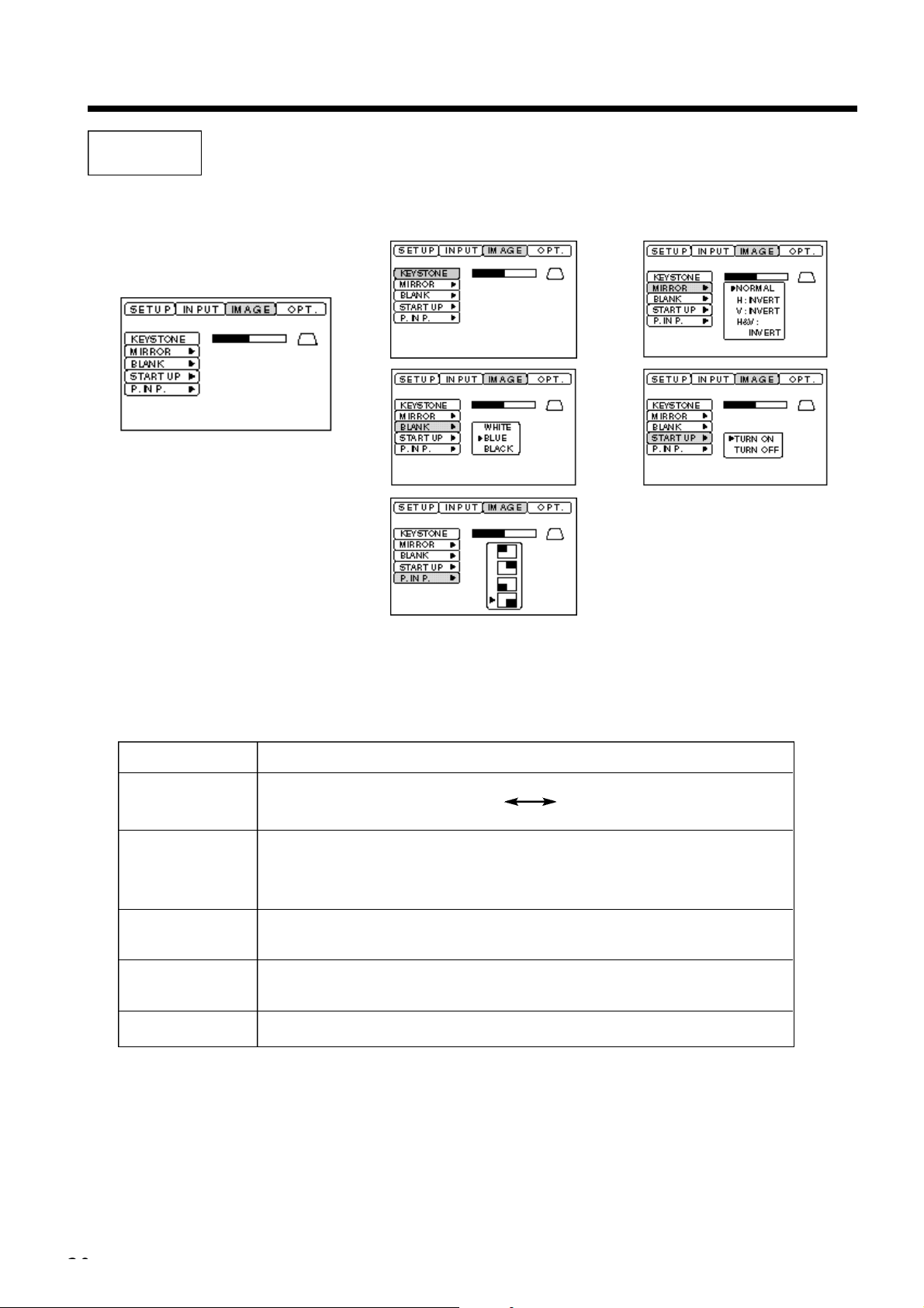
Adjustments and functions (contin u e d )
Adjustment item
KEYSTONE
MIRROR
BLANK
START UP
P in P
Adjustment description
Reduces keystone Reduces keystone
distortion at the bottom distortion at the top
Sets vertical or horizontal inversion of the projected image.
H: horizontal inversion only
V: vertical inversion only
H&V: both horizontal and vertical inversion.
Sets the color to be used for blanking with BLANK ON or when there is no signal.
Blanking is turned on, when there is no signal for approximately 5 min.
Opens and closes the initial settings screen during signal input at start up.
When canceled, the background color will change to blue.
Selects the P in P sub screen display position.
IMAGE
Projection image inversion, etc., can be selected from the IMAGE menu.
Page 21
Adjustments and functions (contin u e d )
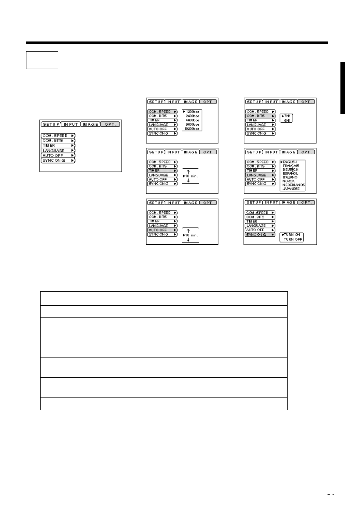
OPT
Communication functions, etc., can be set from the OPT menu.
Adjustment item
COM. SPEED
COM. BITS
TIMER
LANGUAGE
AUTO OFF
SYNC ON G
Adjustment description
Sets the communication speed (5 steps).
Sets the bit configuration for the communication data.
7N1...7 data bits, No parity, 1 stop bit.
8N1...8 data bits, No parity, 1 stop bit.
Sets the timer display time (0 - 99) min.
Selects the menu screen language
(English, French, German, Spanish, Italian, Norwegian, Dutch, Japanese).
Sets the time after which the power will be turned off (standby status) when
there is no input signal. The settings are 1 - 99 min, 0 and None.
Sets the SYNC ON G feature on/off.
Page 22
Connection to the video signal terminals
Connection to the RGB signal terminal
1. Input signals
2. Signal input jacks
1. Input signals
2. Signal input jacks
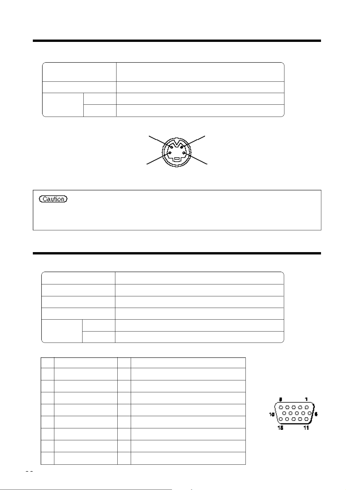
S-VIDEO input (mini DIN 4-pin)
Color signal
Ground Ground
Brightness signal
S-VIDEO signal
VIDEO signal
Audio signal
The priority sequence of the video input jacks is as follows.
(1) S-VIDEO input jack (2) RCA jack input jack
When video signals are being projected, the audio input by the video is output to the audio
output jack (RGB/VIDEO).
Input
Output
Brightness signal 1.0V p-p, 75 Ω terminator
Color signal 0.286V p-p (burst signal), 75 Ω terminator
1.0V p-p, 75 Ω terminator
200mV rms, 20k Ω or less (max. 3.0V p-p)
0∼200mVrms,1k Ω
Video signal Analog, 0.7V p-p, 75 Ω terminator (positive polarity)
Horizontal sync signal TTL level (positive/negative polarity)
Vertical sync signal TTL level (positive/negative polarity)
Compound sync signal TTL level
Input 200mV rms, 20k Ω or less (max. 3.0V p-p)
Audio signal
Output 0~200mVrms,1k Ω
Pin Pin
1 Video input (red) 9 N.C
2 Video input (green) 10 Ground
3 Video input (blue) 11 N.C
4 N.C 12 DDC jack (Display Data Channel)
5 N.C 13 Horizontal sync signal/compound sync signal
6 Ground (red) 14 Vertical sync signal
7 Ground (green) 15 DDC jack (Display Data Channel)
8 Ground (blue)
D-sub 15-pin
shrink jack
Page 23
Connection to the RGB signal terminal (continued)
• Some computers may have multiple display screen modes. Use of some of these modes will
not be possible with this projector.
•Be sure to check jack type, signal level, timing and resolution before connecting this
projector to a computer.
•Depending on the input signal, full-size display may not be possible in some cases.
3. Example of computer signal
Resolution fH fV
H × V (kHz) (Hz)
640 × 400 24.8 56.4 NEC PC9800 Zoom in
640 × 350 37.9 85.1 VESA VGA-1 Zoom in
640 × 400 37.9 85.1 VESA VGA-2 Zoom in
720 × 400 37.9 85.0 VESA TEXT Zoom in
640 × 480 31.5 59.9 VESA VGA-3 Zoom in
640 × 480 35.0 66.7 Mac13"mode Zoom in
640 × 480 37.9 72.8 VESA VGA-3(72Hz) Zoom in
640 × 480 37.5 75.0 VESA VGA-3(75Hz) Zoom in
640 × 480 43.3 85.0 VESA VGA-3(85Hz) Zoom in
800 × 600 35.2 56.3 VESA SVGA(56Hz) Zoom in
800 × 600 37.9 60.3 VESA SVGA(60Hz) Zoom in
800 × 600 48.1 72.2 VESA SVGA(72Hz) Zoom in
800 × 600 46.9 75.0 VESA SVGA(75Hz) Zoom in
800 × 600 53.7 85.1 VESA SVGA(85Hz) Zoom in
832 × 624 49.7 74.5 Mac16"mode Zoom in
1024 × 768 48.4 60.0 VESA XGA(60Hz)
Rating Signal mode Display mode Note 1
SW 1 ON
SW 2 ON
SW 2 ON
SW 4 ON
1024 × 768 56.5 70.1 VESA XGA(70Hz)
1024 × 768 60.0 75.0 VESA XGA(75Hz)
1024 × 768 67.8 85.0 VESA XGA(85Hz)
1152 × 864 67.5 75.0 VESA SXGA(75Hz) Zoom out
1280 × 960 60.0 60.0 VESA SXGA(60Hz) Zoom out
1280 × 1024 64.0 60.0 VESA SXGA(60Hz) Zoom out
1280 × 1024 80.0 75.0 VESA SXGA(75Hz) Zoom out
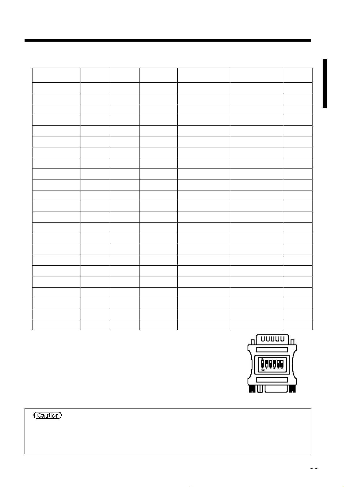
Note 1: The Mac adapter is required for some Mac modes.
Projector is compatible with 13 inch mode and 16 inch mode.
Mac 13" mode=switch 1 and switch 2 are ON.
Mac 16" mode=switch 2 and switch 4 are ON.
(Example 16 inch mode)
Page 24
Connection to the RGB signal terminal (continued)
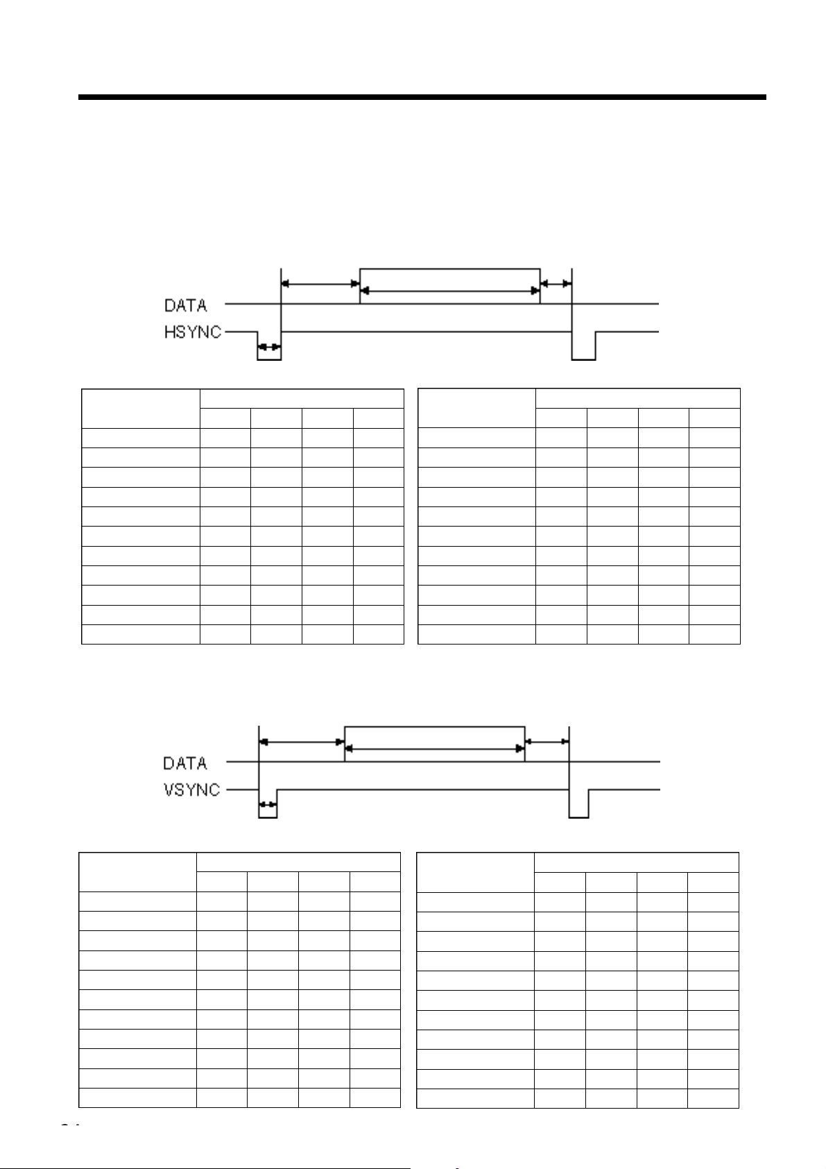
4. Initial set signals
The following signals are used for the initial settings.
The signal timing of some computer models may be different. In such case, refer to pages 17 and 18 and adjust
the V.POSIT and H.POSIT of the menu.
Back porch b
Display interval c
Sync a
Front porch d
Computer/Signal
VGA-1(85Hz) 2.0 3.0 20.3 1.0
VGA-2(85Hz) 2.0 3.0 20.3 1.0
PC-9800 3.0 3.8 30.4 3.0
TEXT 2.0 3.0 20.3 1.0
VGA-3 3.8 1.9 25.4 0.6
Mac 13"mode 2.1 3.2 21.2 2.1
VGA-3(72Hz) 1.3 3.8 20.3 1.0
VGA-3(75Hz) 2.0 3.8 20.3 0.5
VGA-3(85Hz) 1.6 2.2 17.8 1.6
SVGA(56Hz) 2.0 3.6 22.2 0.7
SVGA(60Hz) 3.2 2.2 20.0 1.0
Horizontal signal timing (µs)
a b c d
Back porch b
Computer/Signal
SVGA (72Hz) 2.4 1.3 16.0 1.1
SVGA (75Hz) 1.6 3.2 16.2 0.3
SVGA (85Hz) 1.1 2.7 14.2 0.6
Mac 16"mode 1.1 3.9 14.5 0.6
XGA (60Hz) 2.1 2.5 15.8 0.4
XGA (70Hz) 1.8 1.9 13.7 0.3
XGA (75Hz) 1.2 2.2 13.0 0.2
SXGA (1152 X 864, 75Hz)
SXGA (1280 X 960, 60Hz)
SXGA (1280 X 1024, 60Hz)
SXGA (1280 X 1024, 75Hz)
Display interval c
Horizontal signal timing (µs)
a b c d
1.2 2.4 10.7 0.6
1.0 2.9 11.9 0.9
1.0 2.9 11.9 0.9
1.1 1.8 9.5 0.1
Front porch d
Sync a
Computer/Signal
VGA-1 (85Hz) 3 60 350 32
VGA-2 (85Hz) 3 41 400 1
PC-9800 8 25 400 7
TEXT 3 42 480 1
VGA-3 2 33 480 10
Mac 13"mode 3 39 480 3
VGA-3 (72Hz) 3 28 480 9
VGA-3 (75Hz) 3 16 480 1
VGA-3 (85Hz) 3 25 480 1
SVGA (56Hz) 2 22 600 1
SVGA (60Hz) 4 23 600 1
Vertical signal timimg (lines)
a b c d
Computer/Signal
SVGA (72Hz) 6 23 600 37
SVGA (75Hz) 3 21 600 1
SVGA (85Hz) 3 27 600 1
Mac 16"mode 3 39 624 1
XGA (60Hz) 6 29 768 3
XGA (70Hz) 6 29 768 3
XGA (75Hz) 3 28 768 1
SXGA (1152 X 864, 75Hz)
SXGA (1280 X 960, 60Hz)
SXGA (1280 X 1024, 60Hz)
SXGA (1280 X 1024, 75Hz)
Vertical signal timimg (lines)
a b c d
3 32 864 1
3 36 960 1
3 38 1024 1
3 38 1024 1
Page 25
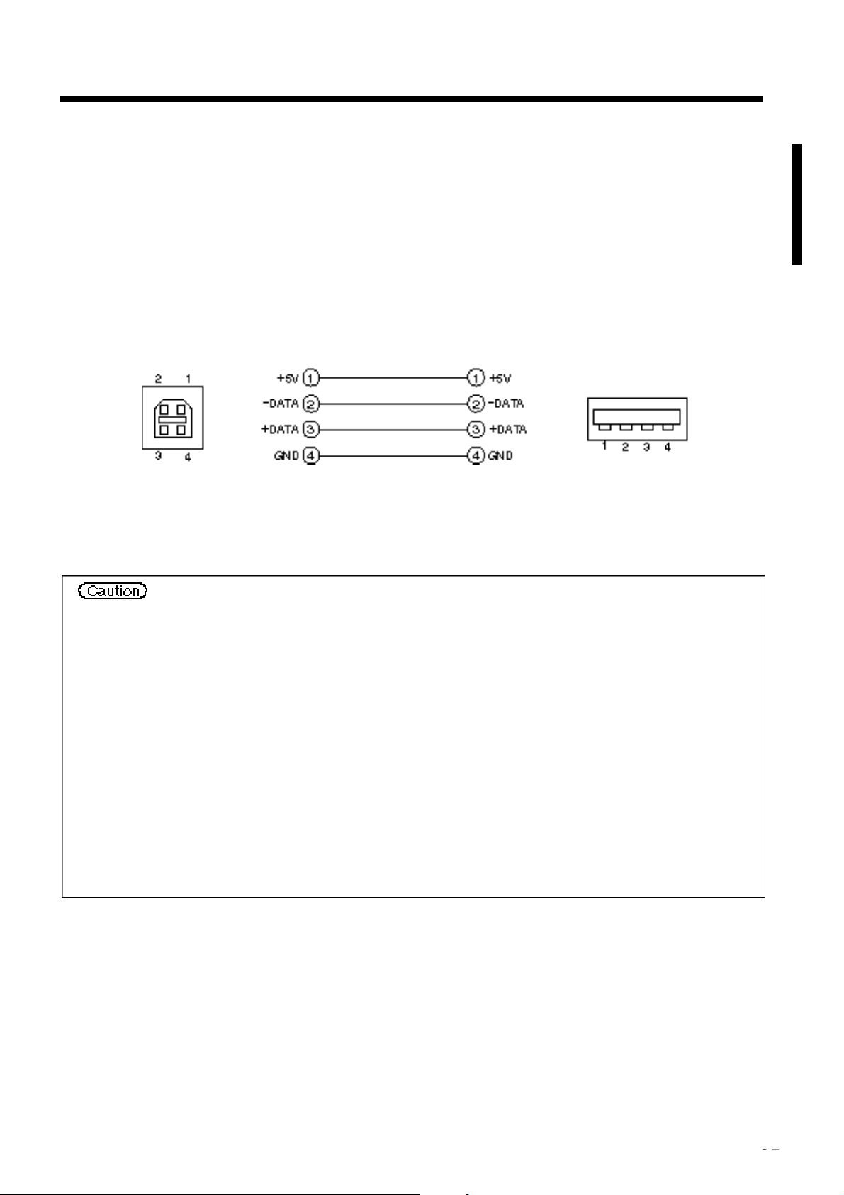
Connecting the USB cable
1. Connect the projector and computer with a suitable commercially available cable. Disconnect the mouse
cable from the projector.
2. Press the INPUT button of the projector or the RGB 1/2 button of the remote control and select the input
where the computer is to be connected.
3. Start the mouse function.
4. Refer to page 10 concerning the remote control of mouse operations.
5. Varying the force with which the DISK PAD button is pressed varies the speed of mouse operation.
USB jack
(B type)
• Before making connections, read the instruction manual of the equipment to be connected.
• Use the optional USB cable to connect.
• Effective with USB only when the mouse is used.
• Do not use with any device other than a personal computer.
• When using with Windows 95, it is necessary to set so that USB can be used with version
OSR 2.1 or higher. Depending on the kind or the virsion of the host controller, operation may
not be possible in some cases.
• With some notebook computers that use a built-in pointing device such as a track ball, the
built-in pointing device will have priority even if a mouse is connected and the mouse may
not be selected.
In such case, disable the built-in pointing device and change the BIOS setting (system setup)
so that an external mouse can be selected. (Check laptop users guide)
After changing the BIOS setting, perform the operations described in 1 - 3 above.
Refer to the computer hardware manual concerning the BIOS setting.
Also, some computers may not have a utility program to operate a mouse. Refer to the
computer hardware manual.
Projector
Computer
USB cable
USB jack
(A type)
Page 26
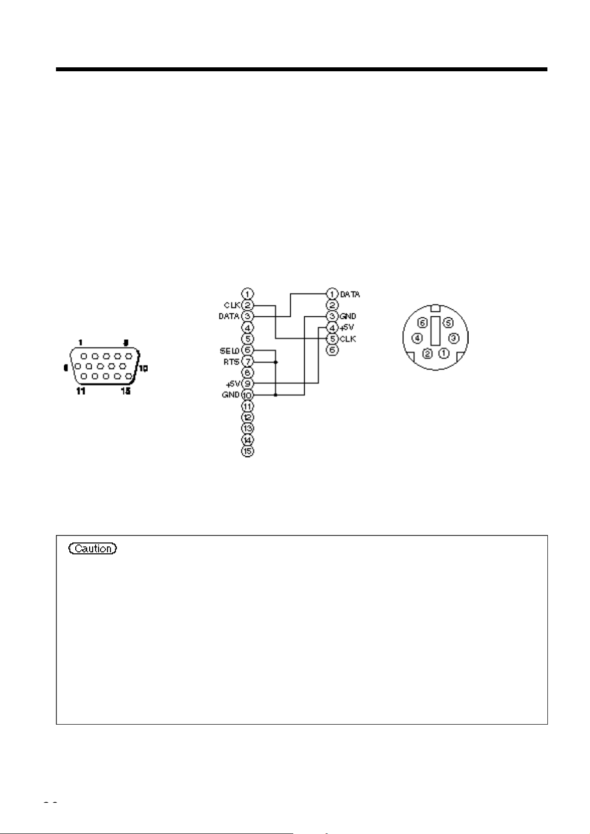
Connection to the control signal terminal
Use the mouse cable provided or a PS/2 mouse cable (for IBM and compatibles).
Cables for ADB mouse (Apple), bus mouse (NEC) and serial mouse are available as options.
1. Mouse functions
(1)Turn off the main power switches of the projector and computer and connect the two units with the cable
provided or an optional suitable commercially available cable. Disconnect the USB cable from the
projector.
(2)Turn on the main switch of the projector (the POWER indicator lamp will light green).
(3) Press the INPUT button of the projector or the RGB button of the remote control and select the input
where the computer is to be connected.
(4) Turn on the computer power supply.
(5) Start the mouse function.
If the mouse has not been started, reboot the computer (soft reboot or reboot buttons).
(6) Refer to page 10 concerning remote control operation.
(7) Varying the force with which the DISK PAD button is pressed varies the speed of mouse operation.
Computer
PS/2 Mouse
Projector
control jack
D-sub 15-pin shrink jack
Projector Computer
Mouse jack Mini
DIN 6-pin
Mouse cable (PS/2)
• Before making connections, read the instruction manual of the equipment to be connected.
• Turn off the projector and computer power supplies before connecting.
Connecting the mouse cable with the computer power on can result in a malfunction.
Use the mouse cable provided or an optional mouse cable to make the connection.
• In the case of notebook type computers with a built-in pointing device such as a track ball, in
some cases the built-in pointing device will have priority even if a mouse is connected and
the mouse may not be selected.
In such case, disable the built-in pointing device and change the BIOS setting (system setup)
so that an external mouse can be selected.
After changing the BIOS setting, perform the operations described in (1) - (3) above.
Refer to the computer hardware manual concerning the BIOS setting.
Also, some computers may not have a utility program to operate a mouse. Refer to the
computer hardware manual.
Page 27
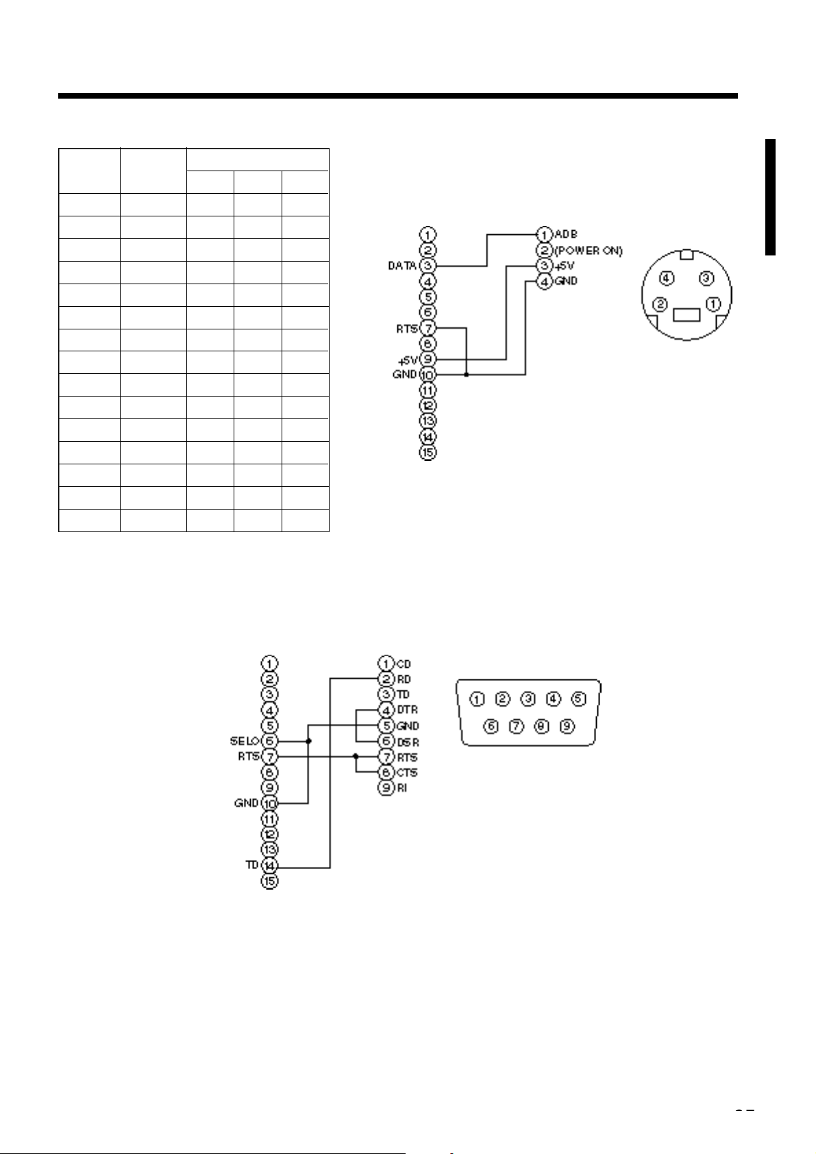
Connection to the control signal terminal (continu e d )
CONTROL signal jack
ADB (Mac) mouse
Pin no. RS-232C
1 YB
2 CLK
3 DATA DATA
4
5
6 SELO SELO SELO
7 RTS RTS RTS RTS
8
9 +5V +5V
10 GND GND GND GND
11
12
13 RD
14 TD TD
15
Mouse
PS/2 ADB Serial
Projector
Computer
Mouse cable (ADB) (option)
Computer
Mouse jack
Mini DIN 4-pin
Serial mouse
Projector Computer Computer
Mouse jack
D-sub 9-pin
Mouse cable (serial) (option)
Page 28
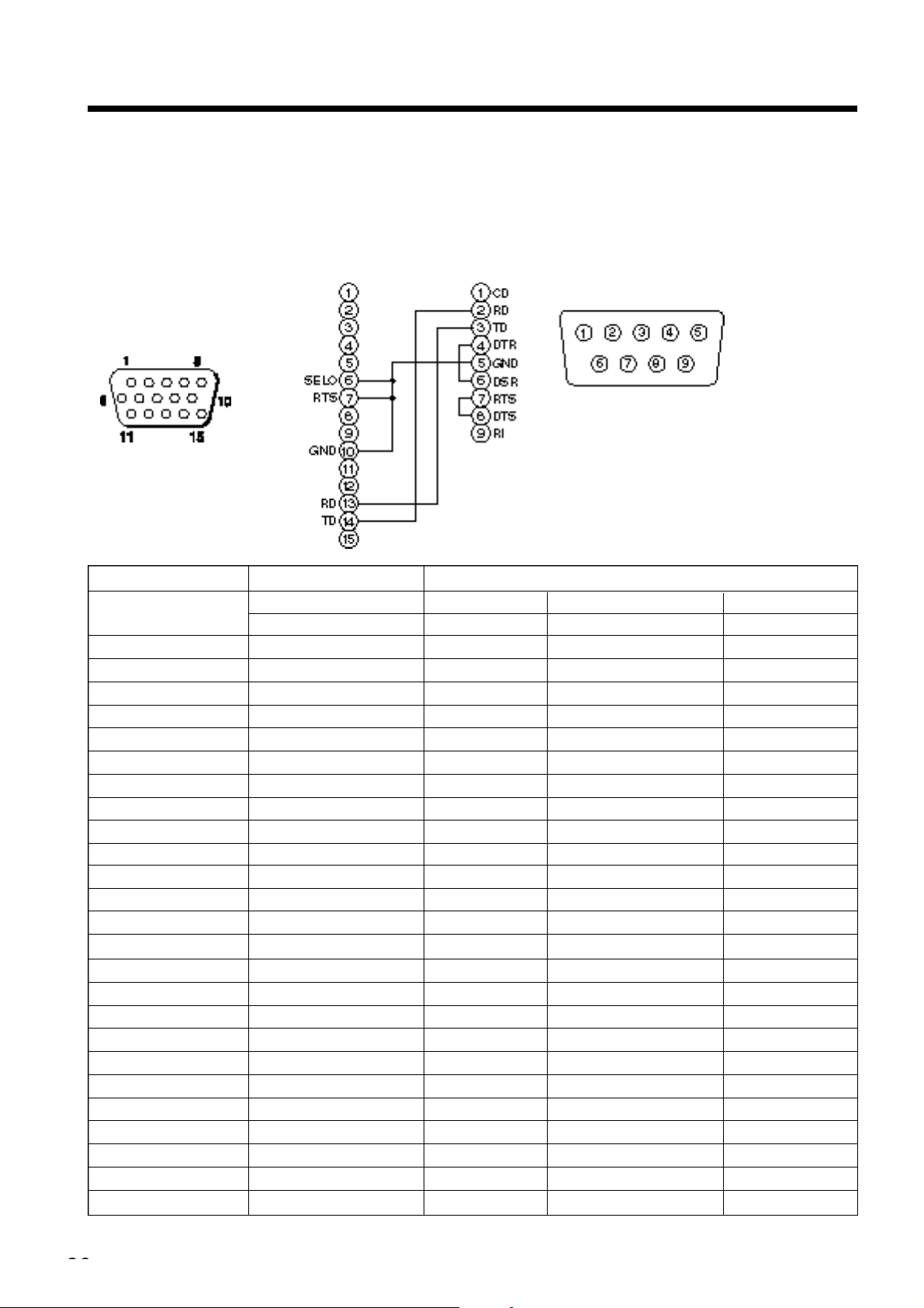
Connection to the control signal terminal (continu e d )
2. RS232C communication
(1) Turn off the projector and computer power supplies and connect with the RS232C cable.
(2) Turn on the computer power supply and, after the computer has started up, turn on the projector power supply.
(3) Refer to page 21 and set the communication speed and the number of communication bits.
(4) Start RS232C communication.
Projector
Control jack
D-sub 15-pin shrink
Projector→computer Computer→projector
Command
MOUSE 11h 05h +1 20h 05h 31h 05h +1 40h 05h
COMMUNICATE 11h 06h +1 20h 06h 31h 06h +1 40h 06h
POWER 11h 11h +1 20h 11h 31h 11h +1
ZOOM 11h 12h +1 –––––– 31h 12h +1 ––––––
FOCUS 11h 13h +1 –––––– 31h 13h +1 ––––––
MIRROR 11h 14h +1 20h 14h 31h 14h +1 40h 14h
INPUT 11h 21h +1 20h 21h 31h 21h +1 40h 21h
(VIDEO)SYSTEM 12h 22h +2 20h 22h 32h 22h +2 40h 22h
VOLUME 11h 23h +1 20h 23h 31h 23h +1 40h 23h
MUTE 11h 24h +1 20h 24h 31h 24h +1 40h 24h
BRIGHT 13h 31h +3 20h 31h 33h 31h +3 40h 31h
CONTRAST 13h 32h +3 20h 32h 33h 32h +3 40h 32h
COLOR 13h 33h +3 20h 33h 33h 33h +3 40h 33h
TINT 13h 34h +3 20h 34h 33h 34h +3 40h 34h
SHARPNESS 13h 35h +3 20h 35h 33h 35h +3 40h 35h
H.PHASE 13h 37h +3 20h 37h 33h 37h +3 40h 37h
H.POSIT 14h 38h +4
H.SIZE 14h 36h +4
V.POSIT 14h 3Ah +4
COLOR BALANCE R 13h 3Bh +3 20h 3Bh 33h 3Bh +3 40h 3Bh
COLOR BALANCE B 13h 3Dh +3 20h 3Dh 33h 3Dh +3 40h 3Dh
AUTO ADJUST 11h 3Ch +1 20h 3Ch 31h 3Ch +1 40h 3Ch
BLANK 11h 41h +1 20h 41h 31h 41h +1 40h 41h
MAGNIFY 11h 15h +1 20h 15h 31h 15h +1 40h 15h
FREEZE 11h 16h +1 20h 16h 31h 16h +1 40h 16h
Projector Computer
RS232C cable
Response code Inquiry code Setting code
1st 2nd data 1st 2nd 1st 2nd data 1st 2nd
––––––
––––––
––––––
Computer
RS232C jack
D-sub 9-pin
Default setting code
––––––
34h 38h +4 40h 38h
34h 36h +4 40h 36h
34h 3Ah +4 40h 3Ah
Page 29

Connection to the control signal terminal (continu e d )
The command code configuration consists of a 2-byte command and the following data.
• The first byte of a command indicates the command type with 3 bits on the MSB side and the data length
with 4 bits on the LSB side.
Projector - computer Computer - projector
‘0xH’ : Error code ‘2xH’ : inquiry code
‘1xH’ : response code ‘3xH’ : setting code
‘70H’ : frame error code ‘4xH’ : default setting code
‘x’ indicates the data length (example: x=2 means a 2-byte command).
• The second byte of a command indicates the command contents.
Command data chart
Item Data code
MOUSE 00h=disable mouse function, 01 ∼ 7Fh=start mouse function
COMMUNICATE 0Xh=8N1, 1Xh=7N1
X0h=1200bps, X1h=2400bps, X2h=4800bps, X3h=9600bps, X4h=19200bps
POWER 3Eh=power off (standby status), 3Fh=power on
ZOOM 01 ∼ 3Fh=Zoom +, 41 ∼ 7Fh=Zoom –
FOCUS 01 ∼ 3Fh=Focus +, 41 ∼ 7Fh=Focus –
MIRROR 00h=Normal, 01h=H : Invert, 02h=V : Invert, 03h=H & V : Invert
INPUT 11h=VIDEO, 21h=RGB1, 22h=RGB2
SYSTEM (VIDEO) 00h 00h=Auto, 00h 01h=NTSC, 00h 04h=NTSC4. 43
00h 02h=PAL, 00h 03h=SECAM, 00h 05h=M-PAL, 00h 06h=N-PAL
VOLUME 00h (low volume) ∼ 24h (high volume)
MUTE 00h=mute off, 01h=mute on
BRIGHT 00h 00h 00h (dark) ∼ 00h 00h 24h (bright)
CONTRAST 00h 00h 00h (low) ∼ 00h 00h 24h (strong)
COLOR 00h 00h 00h (pale) ∼ 00h 00h 24h (dense)
TINT 00h 00h 00h (reddish) ∼ 00h 00h 24h (greenish)
SHARPNESS 00h 00h 00h (soft) ∼ 00h 00h 24h (sharp)
H.PHASE 00h 00h 00h ∼ 00h 00h 24h
H.POSIT 00h 00h 00h 01h (Right) moves one step
00h 00h 00h 7Fh (Left) moves one step
H.SIZE 00h 00h 00h 01h (Large) moves two step
00h 00h 00h 7Fh (Small) moves two step
V.POSIT 00h 00h 00h 01h (Up) moves one step
00h 00h 00h 7Fh (Down) moves one step
COLOR BALANCE R
00h 00h 00h (Light red) ∼ 00h 00h 24h (Dark red)
COLOR BALANCE B
00h 00h 00h (Light blue) ∼ 00h 00h 24h (Dark blue)
AUTO ADJUST 00h (AUTO ADJUST (Play))
BLANK 0Xh=blanking off, 1Xh=blanking on
X=8 Black, X=9 Blue, X=F White
MAGNIFY 00h=normal display, 01h=zoom Magnify display or Magnify ratio up.
7Fh=zoom ratio down
FREEZE 00h=normal display, 01h=still image display
Page 30
Connection to the control signal terminal (continu e d )
Requesting projector status
(1) Send the request code ‘20H’ + ‘yyH’ from the computer to the projector.
(2) The projector returns the response code ‘1xH’ + ‘yyH’ +data to the computer.
Changing the projector settings
(1) Send the setting code ‘3xH’ + ‘yyH’ +data from the computer to the projector.
(2) The projector changes the setting based on the above setting code.
(3) The projector returns the response code ‘1xH’ + ‘yyH’ +data to the computer.
Using the projector default settigns
(1) The computer sends the default setting code ‘40H’ + ‘yyH’ to the projector.
(2) The projector changes the specified setting to the default value.
(3) The projector returns the default value with the response code ‘1xH’ + ‘yyH’ =data.
When a command sent by the projector cannot be understood by the computer
(1) The computer sends the command code ‘3xH’ , ‘4xH’ or ‘4xH’ + ‘yyH’ +data to the projector.
(2) When the command sent by the projector cannot be understood, the error command ‘00H’ + ‘yyH’ is
returned by the computer.
When data sent by the projector cannot be understood
(1) The computer sends the command code ‘3xH’ , ‘4xH’ or ‘4xH’ + ‘yyH’ +data to the projector.
(2) When the command sent by the projector cannot be understood, the the error code ‘0xH’ +‘yyH’ +data is
returned.
When the data length is greater than indicated by the data length code, the projector will ignore the excess data code.
Conversely, when the data length is shorter than indicated by the data length code, an error code will be
returned to the projector.
When a frame error occurs
Repeats 10 times per second until there is some sort of response to the error code 70H + 70H.
When the interval between bytes in one command is 500ms or greater
When a command or data is not sent within 500ms after the command code ‘2xH’ , ‘3xH’ or ‘4xH’ is sent by
the computer, the error command ‘70H’ +‘70H’ will be returned as soon as the 500ms elapses. After this, if
there is no response within 1 sec., a frame error will occur.
The response data in (3) above need not match the setting data in (1).
For example, when the projector cannot set the setting data in (1), the projector may set the
closest value. That value will be used as the response data in (3). Or else the projector will
return the error code ‘0xH’ + ‘yyH’ +data.
• Operation cannot be guaranteed when the projector receives an undefined command or data.
• Provide an interval of at least 40ms between the response code and any other code.
Page 31

Example of system setup
Computer
(notebook type)
Computer
(desktop type)
Speaker (with built-in amp)
Turn power off to all devices before connecting.
Refer to the instruction manual of each device before connecting.
AC input
Video tape recorder with S jack
Video tape recorder
Display monitor
Cleaning the Air filter
Clean the air filter about every 100 hours .
1
2
Turn off the MAIN POWER switch of the projector and
pull out the power cord.
Remove the front air filter.
Page 32

Cleaning the Air filter (continued)
3
Cleaning the air filter with a vacuum cleaner
4
Installing the air filter
When the air filter becomes clogged with dust, etc., the projector power may turn off to
prevent the internal heat level rising. (The lamp indicator color changes to red.)
Do not operate the projector with the air filter removed. (If used with the air filter removed,
dust can enter the LCD panel and produce an adverse effect on image quality.)
Lamp
The light source lamp has a service life.
When used for an extended time, the images may become darker and the colors may deteriorate.
A malfunction could occur if the projector is used in this condition, so replace the lamp with a new one.
The following indicator or a message which appears when the power is turned on will indicate when the lamp
should be replaced.
At such time, it is necessary to replace the lamp with a new one. For lamp replacement, please contact your
dealer or service company.
Even when the lamp is at a high temperature, the power to the projector may cut off to prevent
an excessive temperature increase inside the projector. (The POWER indicator turns off.) Turn
o ff the MAIN POWER switch, wait for some 20 minutes and turn on the MAIN POWER
switch again. If the projector is not recovered after turning on the MAIN POWER switch,
please contact your dealer or service company.
Message table
Screen displays
The following messages are displayed on the screen.
CHANGE THE LAMP“CALL
A MAINTENANCE PERSON”
“CHANGE THE LAMP”
“CALL
A MAINTENANCE PERSON”
“THE POWER WILL
TURN OFF AFTER * hr.”
Blinking of
“CHANGE THE LAMP”
NO INPUT IS DETECTED
SYNC IS OUT OF RANGE
*
1 This display will disappear after 3min. but will reappear when the power is turned on again.
The total lamp usage time is nearing the service life of the lamp. Replace with a new lamp.
The lamp will turn off automatically when the lamp replacement time has been exceeded.
The total lamp time is nearing the lamp replacement time. After (*) hours, the lamp will turn
off. Quickly replace with a new lamp. *1
*Indicates the number of hours until the lamp turns off automatically.
The total lamp time has exceeded the replacement time. The indicator will blink for
approximately 10 min. and then turn off automatically. Replace with a new lamp.
There is no signal input (refer to pages 22, 23).
The current horizontal or vertical frequency cannot be used by this projector (refer to pages 23, 24).
*
1
Page 33

Message table (continued)
Indicators
The POWER indicator, LAMP indicator and TEMP indicator light or blink in the following cases.
POWER
indicator
Lights orange
Flashes green
Lights green
Flashes orange
Lights red
Lights red
Lights red
Flashes red
LAMP
indicator
Turns off
Turns off
Turns off
Turns off
Lights red
Flashes red
Turns off
Flashes red
TEMP
indicator
Turns off
Turns off
Turns off
Turns off
Turns off
Turns off
Flashes red
Turns off
Status
Standby status
Warming up
Operation status *1
Cool down
The lamp does not light. *2
The interior is too hot.
A lamp has not been inserted
or the lamp cover is missing.
The cooling fan is not operating.
The total lamp time has
exceeded the replacement time.
Processing
Wait some time (approx. 20 min.) before
turning the power on again. Clean the air
filter before turning the power on. If the
indicator still lights,
contact your dealer.
Contact your dealer.
Contact your dealer.
Contact your dealer.
When the LAMP or TEMP indicator lights or flashes, turn off the MAIN POWER switch before proceeding. If the problem still persists, contact your
dealer or service company.
*1: When the cooling fan is stopped and the interior becomes overheated, the power will turn off automatically to allow cooling (the indicator will turn
off). In such cases, turn off the projector power, allow the set to cool and then turn the projector power on again. The lamp will then light. If the lamp
does not light, contact your dealer or service company.
*2: In some cases, when the air holes becomes blocked and the interior temperature rises, the lamp will be turned off for protection and the LAMP
indicator will flash red. In such cases, turn off the MAIN POWER switch, allow the set to cool (for approx. 20 min.) and then turn the power on again.
Troubleshooting
Before requesting repair, check in accordance with the following chart. If the situation cannot be corrected, then
contact your dealer.
Symptom
The power is not
turned on.
No video or audio.
Video is present but
no audio.
Audio is present but
no video.
Colors are pale and
color matching is poor.
Images are dark.
Video is blurred.
The LAMP indicator
lights red.
Possible cause
•The main power switch is not turned on.
•The power cord is disconnected.
•The input is not correctly set.
•No signal input.
•The projector is not correctly connected.
•The volume is set to minimum.
•Mute is turned on.
•
Audio is switched to RGB when P in P is on.
•The projector is not correctly connected.
•The brightness adjustment knob is rotated
fully clockwise.
•The lens cap is still on.
Color density and color matching are not
correctly adjusted.
•
Brightness and contrast are not correctly adjusted.
•
The lamp is nearing the end of its service life.
Focus or H PHASE is out of adjustment.
Lamp failure.
Internal overheating.
Remedy
•
Turn on the main power switch.
•
Plug the power cord into an AC power outlet.
•Use the projector or remote control to set.
•Connect correctly.
•Connect correctly.
•
Press VOLUME + on the remote control or display
the menu screen and adjust the volume.
•Press the MUTE button.
•
Displays the Volume bar and switches the Audio input.
•Connect correctly.
•Select BRIGHT with the MENU button and then
press the ( ) key.
•Remove the lens cap.
Adjust the video.
•Adjust the video.
•Replace with a new lamp.
Adjust the focus or H PHASE.
Wait approximately 20 min. and then turn the
power on again.
•
Make sure the ventilation openings are not blocked.
•Clean the air filter.
•
Lower the ambient temperature to 35 degrees C or less.
Page
P.13
P.9
P.8,10,
13,19
P.9,31
P.9,31
P.10,18
P.8,10
P.10
P.9,31
P.17
P.13
P.18
P.18
P.32
P.13,18
P.33
P.31,32
Page 34

Specifications
· These specifications are subject to change without notice.
Product name Desktop Projector
Model DP6850
Display method Three liquid crystal panels, three primary color system.
Liquid crystal Panel size 3.3 cm (1.3 Inch)
panel Drive system TFT active matrix
Number of pixels 786,432 pixels (1,024 horizontal × 768 vertical)
Lens Zoom lens F=1.7~2.3 f=49~64mm
Lamp 190w UHB
Speaker 1.2W + 1.2W (Stereo)
Power supply AC100 ~ 120V, 3.7A / AC220 ~ 240V, 1.5A.
Power consumption 320W
Operating temperature range 0 ~ 35˚C
Size 289mm(W) ×124mm (H) × 345mm (D), 11" (W) × 5" (H) × 14" (D)
Weight (mass) 6kg ,13 lbs
S VIDEO: mini DIN 4-pin jack
VIDEO signal input jacks VIDEO: RCA jack
AUDIO: RCA jack
RGB signal input/output jacks RGB signals: D-sub 15-pin shrink jack
Audio: stereo mini-jack
CONTROL signal jack D-sub 15-pin shrink jack
USB jack B type
Resolution Horizontal 500 TV lines
Compatibility NTSC, PAL, SECAM, NTSC4.43, M-PAL, N-PAL
H. Sync. Range fH; 25~80kHz
V. Sync. Range fV; 56~120Hz
Keystone correction OPTICAL; Fixed 20:1 upward shift, Normal at +10.8˚~8.2˚ projection angle
DIGITAL; +_10%
Noise rating 40dB
Page 35

Dimensional Diagram
Unit: inches
Specifications (continued)
About the warranty and after-service
About the warranty
A warranty is provided for this product. Fill in the necessary items and store in a safe place.
About after-service
When a problem occurs, please check first using the Troubleshooting Chart provided in this instruction manual.
If the problem still persists, contact your dealer or service company.
About repairs during the warranty period
Repairs will be made as described in the warranty.
For details, please read the warranty.
Page 36

About the warranty and after-service (continued)
Limited Warranty
Proxima Corp. (“Proxima”) warrants that each Desktop Projector 6850 (“Product”) projector purchased
from Proxima Corp. is free from defects in materials and workmanship under normal use during the
warranty period said warranty shall commence on the day of purchase by the End-User and continue for
a period of two (2) years.
To exercise the End-User’s rights under this warranty, the Product must be returned at the End-User’s
expense, to Proxima Corporation or to any authorized Proxima Corp. service center. The returned
product must be accompanied by (i) the End-User’s sales receipt or invoice that shows the date of
sale, product type and dealer’s name, and, when returned to Proxima Corporation, (ii) a return
authorization number, issued by Proxima Corporation that is clearly displayed on the outside of the
shipping carton. The Warranty extends only to the original End-User purchase and is not transferable.
EXCLUSIVE REMEDY
During the Warranty Period, Proxima Corp. will, at no additional charge, repair or replace defective
parts or, at the option of Proxima Corporation, replace the entire unit. Proxima Corporation shall
have no other obligation, and repair or replacement shall be the End-User’s exclusive remedy for any
defect in the Product.
WARRANTY LIMITATION AND EXCLUSION
This Limited warranty does not extend to any Product that has been damaged due to accident, unauthorized
modifications, tampering, abuse, misuse, alterations, unusual physical or electrical stress, or to
any Product that has been serviced by other than Proxima Corporation or its authorized agents or which
has been used in any manner other than from ordinary use in the application for which it was intended.
THE FOREGOING WARRANTY IS EXPRESSLY IN LIEU OF ANY OTHER EXPRESS OR IMPLIED WARRANTIES, INCLUDING,
WITHOUT LIMITATION, WARRANTIES OF MERCHANTABILITY OR FITNESS FOR A PARTICULAR PURPOSE. TO THE EXTENT
NOT PROHIBITED BY LAW, ALL STATUTORY WARRANTIES ARE HEREBY WAIVED AND EXCLUDED FROM THIS LIMITED
WARRANTY. PROXIMA CORPORATION EXPRESSLY DISCLAIMS ALL WARRANTIES NOT STATED IN THE LIMITED WARRANTY.
LIMITATION OF LIABILITY
It is understood and agreed that the liability of Proxima Corporation, whether in contract, in tort,
under any warranty, in negligence or otherwise shall not exceed the return of the amount of the purchase
price paid by the End-User and under no circumstances shall Proxima Corporation be liable for
special, indirect or consequential damages. No action, regardless of form, arising out of the agreement
to purchase the Product may be brought by the End-User more than one year after the cause of the action
has accrued.
Page 37

Desktop-Projektor
Modell
DP6850
BEDIENUNGSANLEITUNG
Herzlichen Glückwunsch zum Kauf dieses Desktop-Projektors von PROXIMA. Bitte lesen Sie
diese Bedienungsanleitung zugunsten der korrekten Bedienung aufmerksam. Bewahren Sie die
Anleitung anschließend für späteres Nachschlagen an einem sicheren Platz auf.
Kurzbeschreibung
Der DP6850 ist hell genug zur Füllung eines Raumes
und vielseitig genug zur Erfüllung ihrer hohen
Ansprüche. Die hervorragende Bildqualität und
fortschrittlichen Videoleistungen machen das Gerät
zu einem zuverlässigen Werkzeug für Klassenzimmer
und Konferenzräume.
Merkmale
(1) Digitale Tr a p e z korrektur macht es leicht, ein
R e ch t e ckbild zu projizieren und erlaubt mehr
Aufstellungsmöglichkeiten
(2) Das helle Bild ist ideal für Klassenzimmer und
Konferenzräume
(3) E chte XGA (1024 x 768) Auflösung und Fit-to-
View Anzeige von VGA (640 x 480) durch SXGA
(1280 x 1024) unterstützt volle Bildschirmbilder
von PCs und Macintosh-Computers
(4) F l ex i ble Ansch l u ß m ö g l i chkeiten mit Buch s e n
für bis zu zwei Computern und USB-Maus
(5) Qualitativ hoch w e rt i ge Videoleistung mit Bild-
in-Bild und Unterstützung für die meisten
Videoformate
(6) Motorzoom und -fokussierung bieten
F l exibilität bei der Pro j e k t o r a u f s t e l l u n g ,
während Digitalzoom Nahdar s t e l l u n gen vo n
ausgewählten Bildgegenständen erlaubt
Inhalt Seite
Vor der Inbetriebnahme……………………3
Überprüfung des Lieferumfangs …………8
Bezeichnung und Funktion der Teile ……8
Aufstellung…………………………………12
Grundlegende Bedienung ………………13
Einstellungen und Funktionen …………17
Anschluß an die
Video-Eingangsbuchsen ……22
Anschluß an die RGB-Buchse …………22
Anschließen des USB-Kabels……………25
Anschluß an die Steuersignalbuchse …26
Systemübersicht (Beispiel) ………………31
Reinigen des Luftfilters …………………31
Lampe …………………………………32
Meldungstabelle …………………………32
Fehlersuche ………………………………33
Technische Daten…………………………34
Garantie und Kundendienst………………35
Page 38

Page 39

<Vor dem Betrieb>
Bedeutung der Symbole Zugunsten der korrekten Bedienung des Geräts befinden sich in dieser
Anleitung sowie auf dem Projektor selbst bestimmte Symbole, die auf
Sicherheitsrisiken und entsprechende Vorsichtsmaßregeln hinweisen, um
Körperverletzungen und Sachschäden zu vermeiden. Die Bedeutung dieser
Symbole ist nachfolgend erklärt. Es ist wichtig, daß Sie die folgenden
Sicherheitshinweise aufmerksam durchlesen und verstehen.
WARNUNG
Dieses Symbol weist auf Vorsichtsmaßregeln hin, deren
Mißachtung bei falscher Bedienung zu körperlichen
Verletzungen mit möglicher Todesfolge führen können.
VORSICHT
Dieses Symbol weist auf Vorsichtsmaßregeln hin, deren
Mißachtung bei falscher Bedienung zu Personenverletzungen
oder Sachschäden führen können.
Typische Symbole
Dieses Symbol weist auf eine zusätzliche Warnung (einschließlich
Vorsichtsmaßregeln) hin, wobei eine Abbildung den Textinhalt verdeutlicht.
(Das linksstehende Symbol deutet auf Gefahr durch elektrische Schläge
hin.)
Dieses Symbol weist auf eine unzulässige Handlung hin, wobei eine
Abbildung den Textinhalt verdeutlicht. (Das linksstehende Symbol
bedeutet, daß das Gerät oder eine bestimmte Baugruppe nicht zerlegt
werden darf.)
Dieses Symbol weist auf eine Pflichthandlung hin, wobei eine Abbildung
den Textinhalt verdeutlicht. (Das linksstehende Symbol bedeutet, daß der
Netzstecker aus der Steckdose zu ziehen ist.)
Vor der Inbetriebnahme
Page 40

Den Netzstecke
aus der Steckdos
z i e h e n .
Den Netzstecke
aus der Steckdos
z i e h e n .
G e f a h r
e l e k t r i s c h e r
S c h l ä g e
Nicht
zerlegen.
Nicht in der Nähe von
Wasser verwenden.
[Sicherheitshinweise]
Warnung
■ Bei Auftreten von Betriebsstörungen
Bei fremden Gerüchen oder Rauchentwicklung
•
kann eine Fortsetzung des Betriebs zu Bränden oder
elektrischen Schlägen führen. Schalten Sie das Gerät
in diesem Fall sofort aus, und ziehen den
Netzstecker aus der Steckdose. Wenden Sie sich
anschließend zwecks Reparatur an Ihren
F a c h h ä n d l e r, wenn kein Rauch oder fremde
Gerüche mehr vorhanden sind. Versuchen Sie
niemals das Gerät eigenhändig zu reparieren, um
bestehende Sicherheitsrisikenzu vermeiden.
Wenn kein Bild oder kein Ton vorhanden ist,
•
oder der Ton verzerrt ist,
sollte der Projektor nicht
verwendet werden. Eine
Fortsetzung des Betriebs in
diesem Zustand kann zu
Bränden oder elektrischen
Schlägen führen. Schalten Sie das Gerät in
diesem Fall sofort aus, ziehen Sie den
Netzstecker aus der Steckdose, und wenden Sie
sich zwecks Reparatur an Ihren Fachhändler.
Falls Wasser in den Projektor eindringt, schalten
•
Sie das Gerät sofort aus, ziehen Sie den
Netzstecker aus der Steckdose, und wenden Sie
sich zwecks Reparatur an Ihren Fachhändler.
Den Netzstecker
aus der Steckdose
z i e h e n .
■ N i cht auf unstabilen Flächen aufstellen.
Stellen Sie den Projektor nicht auf
•
unstabilen Flächen, wie z.B. auf
einem wackeligen Gerüst, oder auf
schrägen Unterböden auf, da das
Gerät hierduch herunterfallen und
Verletzungen verursachen kann.
■ Niemals das Gehäuse öffnen.
Ö ffnen Sie niemals das
•
Gehäuse des Projektors. Im
Inneren des Gehäuses befinden
sich Hochspannungsteile, die
elektrische Schläge
verursachen können. Wenden Sie sich zur
Inspektion der Bauteile, Einstellung und
Reparatur an Ihren Fachhändler.
■ Nicht modifizieren.
Der Projektor darf nicht baulich verändert werden,
da hierbei die Gefahr elektrischer Schläge besteht.
Nicht
zerlegen.
■ Niemals im Badezimmer verwenden.
Verwenden Sie den Projektor niemals
im Badezimmer, da hierbei die Gefahr
elektrischer Schläge besteht.
■ Keine Fremdkörper ins Gehäuse steck e n .
Stecken Sie keine Metallobjekte in
•
die Belüftungsöffnungen usw. des
Projektors, und achten Sie darauf,
daß keine derartigen Objekte ins
Gehäuse fallen, da hierdurch
Brände und elektrische Schläge entstehen
können.
Falls ein Fremdkörper in das Gehäuse
•
gelangt, schalten Sie das
Gerät sofo rt aus, ziehen Sie
den Netzstecker aus der
S t e ck d o s e, und wenden Sie
s i ch zwecks Reparatur an
Ihren Fachhändler.
Eine Fortsetzung des Betriebs in
diesem Zustand kann zu Bränden oder
elektrischen Schlägen führen. Besondere
Vorsicht ist in Haushalten mit Kindern
geboten.
■ N i cht bei eing e s ch a l t e t e r
Lampe durch das Objektiv
schauen.
Blicken Sie niemals bei eingeschalteter
Lampe durch das Objektiv. Das extrem helle Licht
kann das Sehvermögen beeinträchtigen. Besondere
Vorsicht ist in Haushalten mit Kindern geboten.
■ E rs ch ü t t e r u n gen und Stöße ge gen den
P rojektor vermeiden.
Falls das Gehäuse des Projektors durch
Herunterfallen beschädigt wird, schalten
Sie das Gerät sofort aus, ziehen Sie den
Netzstecker aus der Steckdose, und
wenden Sie sich zwecks Reparatur an
Ihren Fachhändler. Eine Fortsetzung des
Betriebs in diesem Zustand kann zu
Bränden oder elektrischen Schlägen führen.
Page 41

Warnung
■
Den Projektor niemals in einen Behälter
stellen, der Flüssigkeit enthält.
Stellen Sie niemals Blumenv a s e n ,
B l u m e n t ö p fe, Tassen, Ko s m e t i k a
oder Flüssigkeiten jeglicher Art
auf den Pro j e k t o r. Ein Ve r s c h ü t t e n
kann zu Bränden oder elektrischen Schlägen
führen.
■ Nur mit der korrekten
Netzspannung betreiben.
Betreiben Sie den Projektor ausschließlich
mit der vorgeschriebenen Netzspannung. Ein
Anschluß an andere Netzversorgungsquellen kann zu
Bränden oder elektrischen Schlägen führen.
■ Das Netzkabel vorsichtig handhaben.
Das Netzkabel nicht besc h ä d i gen, kürz e n ,
•
modifizieren oder knic k e n . Das
niemals erhitzen, daran ziehen oder
schwere Gegenstände darauf stellen.
Derartige Handlungen können zu
Bränden oder elektrischen Schlägen
führen.
• Nicht am Netzkabel ziehen.
•
Keine schweren Gegenstände auf das Kabel stellen.
• Das Kabel vor Beschädigung schützen.
• Nicht in der Nähe von Heizkörpern verlegen.
Das Netzkabel nicht unter dem
•
P rojektor verlegen. Hierdurch können
Brände oder elektrischen Schläge verursacht
werden. Ebenso sollte das Kabel nicht durch
einen Teppich oder dergleichen verdeckt werden,
da versehentlich schwere Gegenstände auf das
verdeckte Kabel gestellt werden könnten.
Wenden Sie sich an Ihren Fachhändler, falls
•
das Netzkabel beschädigt ist (freiliegende
oder gebrochene Kabeladern usw. ) ,
da eine Weiterverwendung zu
Bränden oder elektrischen Schlägen
führen kann.
Darauf achten, daß der Netzstecker nicht
•
verstaubt ist und durch Einschieben einer
Messerklinge auf Lockerung überprüfen.
N e t z k a b e l
■
Den Lasterstrahl des Fernbedien u n g s t e i l s
n i cht auf die Au gen von Pe rsonen ric h t e n .
Aus dem Fernbedienungsteil geht ein
•
Laserstrahl aus. Schauen Sie niemals
direkt in das Laserfenster des
Fernbedienungsteils, und richten Sie den
Laserstrahl nicht direkt auf andere
Personen.
Auf die Augen treffende Laserstrahlen
können das Sehvermögen gefährden.
Besondere Vorsicht ist in Haushalten mit
Kindern geboten.
■
Da bei einge s chalteter Lampe hohe
Temperaturen erzeugt werden, dürfen keine
Gegenstände vor die Linse gelegt werden.
Laserstrahlfenster
Page 42

■
N i cht auf den Projektor setzen und keine
s chweren Gegenstände darauf ab l e ge n .
•
N i cht auf den Projektor setzen.
Der Projektor kann hierdurch
umfallen und Ve r l e t z u n g e n
verursachen. Besondere Vorsicht
ist in Haushalten mit Kindern
geboten.
•
D u rch Au f l e gen schwerer Gege n s t ä n d e
kann der Projektor umfallen und
Ve r l e t z u n gen verurs a ch e n .
Wenn schwere Gegenstände auf den
Projektor gestellt werden, besteht die Gefahr
des Umkippens oder Herunterfallens,
wodurch Unfälle mit Ve r l e t z u n g e n
verursacht werden können.
■
Die Belüftungsöffnu n gen nicht b l o ck i e r e n .
Die Belüftungsöffnu n gen des Pro j e k t o rs
freihalten.Ein Blockieren dieser Öffnungen kann
zu Brandentwicklung durch Überhitzen führen.
Den Projektor nicht auf die Seite stellen
und nicht in enge, schlecht belüftete
Nischen schieben. Weiterhin sollte der
Projektor nicht auf Teppichen abgestellt
oder mit Tischdecken o. dergl. verdeckt werden.
Bei der Aufstellung des Projektors darauf achten,
daß die Belüftungsöffnungen mindestens 30 cm
von der Wand entfernt sind.
■ Wartung und Pflege
Vor der Wartung und Pflege des
Projektors aus Sicherheitsgründen
das Netzkabel von der Steckdose
t r e n n e n .
■ Batteriebetrieb
•
Den Projektor aussch l i e ß l i ch mit
Batterien des vo rge s ch r i e b e n e n
Typs betreiben.
Niemals neue
zusammen mit alten Batterien einlegen,
da Batterien hierdurch platzen und
Brände auslösen oder Verletzungen durch
auslaufende Batteriesäure verursachen können.
•
Beim Einlegen der Batterien auf die
korrekte Au s r i chtung der
Plus- und Minuspole ach t e n .
Falsches Einlegen der Batterien kann
zu Verletzungen oder zur Verschmutzung der
Umgebung durch giftige Batteriesäure führen.
■ Den Projektor alle zwei Jahre innen
säubern lassen.
Lassen Sie den Projektor etwa alle zwei
Jahre von einem F a chhändler innen
s ä u b e r n . Im Projektor angesammelter Staub
kann zu Bränden oder Betriebsstörungen
führen, falls der Projektor längere Zeit
nicht gesäubert wurde. Durch Säubern
des Projektor vor Beginn einer
luftfeuchten Jahreszeit (Regenzeit o. dergl.) lassen
sich besonders gute Ergebnisse erzielen. Auskünfte
hierzu erteilt der Fachhandel.
■ Nicht an luftfeuchten oder staubigen
Plätzen aufstellen.
•
Den Projektor nicht an
l u f t fe u chten oder staubig e n
P l ä t zen aufstellen, da hierdurch Brände
oder elektrische Schläge verursacht werden
können.
•
Au f s t e l l p l ä t ze in der Nähe einer
Ko chstelle oder eines Luftbefe u ch t e rs
vermeiden sowie Plätze, an denen ölige r
R a u ch oder hohen Luftf e u ch t i g k e i t
vorhanden ist. Derartige Umgebungen
können Brände oder elektrische Schläge
verursachen.
■ Die Fußrollenbremse verwenden.
Bei der Aufstellung des Pro j e k t o rs auf
einem Stand mit F u ß rollen ist die
F u ß rollenbremse zu verwenden,
um ein Umfallen oder
We g r u t s chen des Stands und möglich e
Pe rs o n e nv e r l e t z u n gen zu vermeiden.
■ Vo rs i cht beim Umgang mit dem
N e t z k a b e l .
•
Das Netzkabel von Heizkörpern entfe r n t
halten.
Andernfalls kann die
Kabelisolierung schmelzen und Brände
oder elektrische Schläge die Folge sein.
•
Den Netzstecker nicht mit
nassen Händen berühren, um elektrische
Schläge zu vermeiden.
Vorsicht
Den Netzstecker
aus der Steckdose
z i e h e n .
Page 43

■ Übermäßig heiße Plätze vermeiden.
Den Projektor nicht an Plätzen
aufstellen, an denen das Gerät
direkter Sonnenbestrahlung oder
Wärmequellen, wie z.B. einem Herd,
ausgesetzt ist. Andernfalls können
Gehäuse und Innenbauteile durch die
Hitzeeinwirkung beschädigt werden.
■ Lautstärke
Die Lautstärke aus Rücksicht auf andere Leute
auf einen angemessenen Pegel einstellen. Bei
Nacht sollte die Lautstärke niedrig eingestellt
und die Fenster geschlossen werden, um
Nachbarn nicht zu verärgern.
■ Objektivpflege
Das Objektiv mit einem handelsüblichen
Reinigungstuch (für Objektive, Brillengläser
u s w.) sauber wischen. Darauf achten, das
Objektiv nicht mit harten Objekten zu verkratzen.
■ Gehäusepflege
•
Durch Abwischen mit flüchtigen Lösungen, wie
z.B. Benzol, Verdünner usw., kann sich das aus
K u n s t s t o ff bestehende Gehäuse verfärben oder
der Lack abblättern.
•
Bitte vor dem Abwischen mit chemischen
Mitteln die aufgedruckten Anweisungen lesen
und befolgen.
•
Niemals flüchtigen Substanzen (wie z.B.
Insektenschutzmittel) auf das Gehäuse sprühen,
um ein mögliches Verfärben oder eine
Beschädigung der Lackierung usw. zu vermeiden.
•
Zum Sauberwischen von Gehäuse und
Bedienfeld ein weiches Tuch verwenden. Bei
starker Verschmutzung eine neutrale
Reinigungslösung mit Wasser verdünnen und
ein Tuch darin anfeuchten und auswringen.
Nach dem Sauberwischen mit einem
trockenen Tuch nachwischen. Niemals
unverdünnte Reinigungslösung direkt auf das
Gehäuse auftragen.
■ Längerer Betrieb
Bei längerem Betrieb sollten zwischendurch
Pausen eingelegt werden, um einer Ermüdung
der Augen vorzubeugen.
Vorsicht
Den Netzstecker niemals durch Ziehen
•
am Kabel von der Steckdose trennen.
Brände oder elektrische Schläge ausgelöst
werden. Den Netzstecker deshalb stets am
Stecker haltend aus der Steckdose ziehen.
■ Wenn der Projektor längere Zeit nicht
benutzt wird:
Wird der Projektor, z.B. aufgrund einer
bevorstehenden Reise o. dergl., über
längere Zeit nicht benutzt, sollte aus
Sicherheitsgründen der Netzstecker
aus der Steckdose gezogen werden.
Darüber hinaus sollte der Objektivdeckel angesetzt
werden, um die Objektivoberfläche vor Kratzern zu
s c h ü t z e n .
Den Netzstecker
aus der Steckdose
z i e h e n .
■ Transport des Projektors
Beim Transport des Projektors immer
•
sicherstellen, daß der Objektivdeckel
aufgesetzt ist, der Netzstecker aus der
Steckdose gezogen ist und alle externen
Anschlüsse abgetrennt sind.
Den Projektor vor Erschütterungen
und Stößen bewahren, um
Betriebsstörungen zu vermeiden.
Bei einer Aufstellung im Freien, ist der Projektor
•
vor Nässe durch Regen usw. zu schützen. Sollte
der Projektor versehentlich naß werden, muß er
vor der weiteren Ve r w e n d u n g
vollständig trocken gewischt werden.
Ein fortgesetzter Betrieb im nassen
Zustand kann zu Bränden oder
elektrischen Schlägen führen.
Den Netzstecker
aus der Steckdose
z i e h e n .
[Allgemeine Sicherheitshinweise]
Page 44

Überprüfung des Lieferumfangs
Den Kartoninhalt überprüfen und vergewissern, daß alle Teile vollständig vorhanden sind. Falls Teile fehlen, bitte an Ihren
Fachhändler wenden.
• Das Fernbedienungsteil in einem Abstand von etwa 5 m oder weniger vor dem Empfangsfenster für
Fernsteuerungssignale verwenden und dabei in einem Winkel von 30 Grad nach links und rechts halten.
Projektor
Bereitschafts-/Ein-Taste (STANDY/ON)
Diese Taste dient zum Ein- und Ausschalten der
Netzversorgung. Nach dem Ausschalten
befindet sich Projektor im Bereitschaftsmodus.
Einzelheiten hierzu enthält die Seite 13 und 14.
Stummschaltttaste (MUTE)
Diese Taste dient zum Ein- und
Ausschalten des Tons. Zum Ausschalten
des Tons einmal drücken und zum
Wiedereinschalten noch einmal drücken.
Zoomtaste (ZOOM)
Diese Taste dient zum Einstellen
der Bildgröße (siehe Seite 13).
Die Betriebsanzeige (POWER)
Dieses Lämpchen leuchtet oder blinkt im
Bereitschaftsmodus und während des
Betriebs. Einzelheiten hierzu auf Seite 33.
Temperatur-Warnleuchte (TEMP)
Blinkt, wenn der Ventilator versagt.
Einzelheiten hierzu auf Seite 33.
Infrarotempfänger für
Fernbedienung
Objektiv
Objektivdeckel
Lautsprecher
Gebläse
(Einlaßseite)
Gebläse
(Auslaßseite)
Tragegriff
Batterien für
Projektor Fernbedienungsteil
Fernbedienungsteil
Bedienungsanleitung
(diese Anleitung)
Netzkabel × 3 110V-USA
220V-Grofßbritannien,
Europa
3 - S t e c k e r
V i d e o / A u d i o - k a b e l
RGB-Kabel
(15-15 pin M/M)
Mac-Adapter
mit DIP-Schalter
S - V i d e o - K a b e l
(S-Video DIN-mini 4pin)
S t e r e o - M i n i b u c h s e -
K a b l e
Bezeichnung und Funktion der Teile
Fokustaste (FOCUS)
Diese Taste dient zum Scharfstellen des Bilds
Lampenanzeige (LAMP)
Leuchtet oder blinkt, wenn die Temperatur im Projektor
ansteigt oder die Lampe nicht brennt.
Einzelheiten hierzu auf Seite 33.
auf der Leinwand stellen (siehe Seite 13).
Eingangswahltaste (INPUT)
Diese Taste zum Umschalten auf eine andere
Eingangsquelle drücken. Die Eingangsquelle wechselt bei
jedem Tastendruck in der nachstehenden Reihenfolge:
RGB1 RGB2 VIDEO
Menütaste (MENU)
Diese Taste dient zum Abrufen des Menübilds.
Einzelheiten hierzu auf Seite 17 - 21.
Rückstelltaste (RESET)
Diese Taste dient zum Rückstellen auf die werksseitig
voreingestellten Werte. Einzelheiten hierzu auf Seite 10.
17. 25. 26.
Mauskabel × 3
Lautsprecher
Page 45

Bezeichnung und Funktion der Teile (Fortsetzung)
Videoeingangsbuchse
(VIDEO IN)
S-Video-Eingangsbuchse (S-VIDEO IN)
Vierpolige DIN-Minibuchse
Video-Eingangsbuchse (VIDEO IN)
RCA-Buchse
L/R-Audio-Eingangsbuchse
(AUDIO L/R IN)
RCA-Buchse
Netzeingangsbuchse (AC IN)
Dient zum Anschließen des
Zusatznetzkabels.
RGB-Eingangsbuchse
(RGB IN)
15polige D-sub-Halbformatbuchse
(1/2)
Steuerbuchse
(CONTROL)
15polige D-sub-Halbformatbuchse
Audioausgangsbuchse (AUDIO OUT - RGB/VIDEO)
Stereo-Minibuchse
Audioeingangsbuchse (AUDIO IN)(RGB)
Stereo-Minibuchse
RGB-Ausgangsbuchse (RGB OUT)
15polige D-sub-Halbformatbuchse
U S B - b u c h s e
Der Mauscursor kann über
Fernbedienung durch
Anschluß eines PCs
gesteuert werden.
Anschluß an die Netzeingangsbuchse (AC IN)
Darauf achten, den Stecker des Zusatznetzkabels so weit wie möglich
in die Buchse AC IN einzuschieben. Ein lockerer Anschluß kann zu
Bränden oder elektrischen Schlägen führen.
Infrarotempfänger für
Fernbedienung
Hauptnetzschalter
Dient zum Ein- und Ausschalten
des Geräts
: OFF
: ON
Hauptnetzschalter
Sicherheitsschlitz
Mit Kensington-Schloß verwenden
Page 46

Bezeichnung und Funktion der Teile (Fortsetzung)
Fernbedienungsteil
Fokustaste (FOCUS)
Diese Taste dient zum Scharfstellen des Bilds
auf der Leinwand (siehe Seite 13).
Zoomtaste (ZOOM)
Diese Taste dient zum Einstellen der Bildgröße
(siehe Seite 13).
Standbildtaste (FREEZE)
Zum Ein- und Ausschalten der FesthaltenFunktion (Standbild).
(Siehe Seite 15)
Automatikmodustaste (AUTO)
*3
Zum Ausführen der automatischen Einstellung.
Vergrößerungstaste
(MAGNIFY)
Dient zum Vergrößern des gezeigten Bildes.
(Siehe Seite 16)
Bild-in-Bild-Taste (P IN P)
*2
Zum Einschalten der Bild-in-Bild Funktion
(Zeigt ein kleines Videosignalbild im RGBSignal).
Bei jedem Tastendruck wird der Betrieb in
der folgenden Reihenfolge umgeschaltet:
(1) Kleiner Nebenbildschirm
(2) Großer Nebenbildschirm (3) Aus.
(1) ∼(3)
(Siehe Seite 20)
Schwarzabtastung-Taste
(BLANK)
Zum Ein- und Ausschalten der
Schwarzabtasteung. (Siehe Seite 20)
*3
Auto-Einstellfunktion
Der Projektor stellt automatisch 4 Punkte ein (V.POSIT, H.POSIT,
H.PHASE, H.SIZE)
Wenn Sie AUTO wählen (den Cursor aus der manuellen Bedienposition
nach rechts bewegen), erscheint das AUTO-Bestätigungsmenü wie unten
gezeigt.
VIDEO-, RGB-Taste
Diese Taste dient zum Wählen der Eingangsquelle
(siehe Seite 13, 19).
Bereitschafts-/Ein-Taste
(STANDY/ON)
Diese Taste dient zum Ein- und Ausschalten der
Netzversorgung. 1 Sekunde oder länger drücken, um
das Gerät auszuschalten (auf Bereitschaftsbetrieb).
(Siehe Seite 13 und 14)
Steuerfläche (DISK PAD) / LINKE MAUS-Taste
*
(1) Dient zum Wählen von Menügegenständen
nach Abruf des Menüs (siehe Seite 16-18).
(2) Wenn das Menü nicht erscheint, sind die Shift-
Funktion und Links-Klick-Funktion der
Computermaus aktiv.
*1
(3) Nach dem Drücken der Taste POSITION kann
das Bild nach oben, unten, links und rechts
bewegt werden.
Menü-Taste (MENU)
*
Dient zum Ein- und Ausschalten der
Bildschirmanzeige. (Siehe Seite 17 - 21).
*
*
Diese Funktionen sind nicht in Betrieb, während die anfängliche Bildschirmmeldung “KEIN EINGANG ERKANNT” oder “SYNC LIEGT AUSSERHALB DES BEREICHS” angezeigt wird.
*
*1
POSITION Symbol
Wenn die POSITION-Taste gedrückt wird, erscheint das bewegliche Display-
Symbol unten rechts auf dem Bildschirm.
Während das Symbol angezeigt wird, können Sie die POSITION-Taste bedienen.
*2
“P in P” -Funktion.
Mit der P in P-Funktion werden Signale zu sowohl RGB als auch VIDEO
angelegt. Diese Funktion arbeitet nur, wenn das RGB-Signal gewählt ist.
Es gibt kein Display, wenn kein Signal vorhanden ist, und wenn das Signal
außerhalb des Sync-Bereichs ist.
Wenn Bild-in-Bild verwendet wird, wird Audio automatisch auf Video
umgeschaltet. Bei Bild-in-Bild kann der Toneingang automatisch durch
Drücken der Tasten VOL und VOL an der Fernbedienung
umgeschaltet werden, wobei der Audiobalken gezeigt wird und indem das
DISK-PAD während der Anzeige nach links und rechts verschoben wird.
*4
LASER-Taste (LASER)
Diese Taste dient zum Ein- und Ausschalten des Laserstrahls.
Siehe Seite 11 über Verwendung und Vorsichtsmaßregeln.
Position-Taste (POSITION)
*
Position drücken, und dann das Maus-Diskpad
verwenden, um die Bildposition zu verschieben (nur
RGB-Modus)
(Siehe Seite 16)
Mausrückstell-/Rechtstaste
*
(MOUSE / RESET RIGHT)
(1)
Funktioniert bei angezeigtem Menü als
Rückstelltaste. Diese Taste drücken, um zu den
Anfangseinstellungen zurückzukehren.
(2)
Dient zum Anklicken der rechten Maustaste, wenn
das Menü nicht angezeigt ist (siehe Seite 25, 26).
(3)
Wenn diese Taste nach dem Rollen des Bildes mit
*1
POSITION gedrückt wird, wird das Bild in
Ausgangsstellung zurückgestellt.
*
Lautstärketaste (VOLUME)
Diese Taste dient zum Einstellen der Lautstärke des
Tons. Ein Drücken der Plusttaste [ ] erhöht und ein
Drücken der Minustaste ( ) senkt die Lautstärke.
Wenn kein Videosignaleingang vorhanden ist, ist
Betrieb nicht möglich, wenn das Eingangsvideosignal
außerhalb des Synchronisationsbereiches ist.
Stummschaltttaste (MUTE)
*
Diese Taste schaltet den Ton stumm. (Zum
Annullieren die Taste PLAY erneut drücken.)
Zeituhr-Taste (TIMER)
Schaltet die Anzeige der Zeiteinstellung durch den Timer auf
dem Menü-Bildschirm Ein und Aus.
Der Timer wird nicht angezeigt, wenn “KEIN EINGANGSSIGNAL
ERKANNT” wird, wenn “SYNC LIEGT AUSSERHALB DES
BEREICHS” angezeigt wird oder während dem Austasten
(blanking) oder Einfrieren (freezing) des Bildschirms.
Siehe Seite 21 über die Methode zur Einstellung des Timers.
*
*4
Bedienungsweise des “Disk Pad” (kreisförmige Schaltfläche)
• Zum Bewegen und Auswählen kippen Sie das “Disk Pad” in die
gewünschte Richtung.
• Drücken Sie die “Disk Pad” - Schaltfläche ein, um die Funktion der
linken Maustaste auszuführen.
• Ein Mauskabel wird benötigt, wenn eine Maus verwendet werden soll.
(Siehe Seite 26 und 27.)
Page 47

Bezeichnung und Funktion der Teile (Fortsetzung)
Einlegen der Batterien Einlegen von R06-Batterien in das Fernbedienungsteil
Der Laserzeiger an der Fernbedienung dient als Zeigevorrichtung.
und richten Sie den Laserstrahl nicht direkt auf andere Personen.
Laserstrahlen können das Sehvermögen gefährden.
1
• Die automatische Einstellung kann bis zu 30 Sekunden in Anspruch nehmen.
• Auto-Einstellung arbeitet möglicherweise in bestimmten Situationen nicht korrekt, je nach angeschlossenem Computer und Signal.
• Immer sicherstellen, daß die Bilder auf Vollgröße ausgedehnt werden, wenn Bilder mit niedriger Auflösung gezeigt werden.
• Nach der Auto-Einstellung kann das Bild in manchen Fällen aufgrund der automatischen Einstellung des Signalpegels leicht dunkel erscheinen.
• Auto-Einstellung kann nicht ausgeführt werden, wenn die anfängliche Anzeige “NO INPUT IS DETECTED” oder “SYNC IS OUT OF RANGE” bei
FREEZE oder MAGNIFY ist.
• Die “Auto Adjust” - Funktion (automatische Nachstellung) wird ausgeführt, wenn folgende Operationen durchgeführt werden.
1.Wenn die Art des Eingangssignals geändert wird.
2.Wenn die “Auto Adjust” (AUTO) - Taste gedrückt wird.
• Die Meldung AUTO IN PROGRESS erscheint während der automatischen Nachstellung auf dem Bildschirm.
• Die Bildschirmanzeige kann während der automatischen
Nachstellung unterbrochen werden. Dies ist jedoch keine Fehlfunktion.
• Nur die Ports RGB1 oder RGB2 können für das Eingangssignal verwendet werden.
• Die “Auto Adjust” - Funktion kann auch mit den Bedienungstasten am Hauptgerät ausgefährt werden.
Den Batteriefach d e ck e l
abnehmen.
Drücken Sie den Knopf,
während Sie den
Batteriedeckel anheben.
2Einlegen der Batterien
Auf die korrekte Ausrichtung
der Plus- und Minuspole
a c h t e n .
3
Den Batteriefach d e ckel wieder anbringe n .
Vo rs i ch t s m a ß r e geln für den
Batteriebetrieb
Den Projektor ausschließlich mit Batterien des vorgeschriebenen Typs
•
betreiben. Niemals neue zusammen mit alten Batterien einlegen, da
Batterien hierdurch platzen und Brände auslösen oder Verletzungen
durch auslaufende Batteriesäure verursachen können.
Beim Einlegen der Batterien auf die korrekte Ausrichtung der
•
Plus- und Minuspole entsprechend den Symbolen im Batteriefach
achten.Falsches Einlegen kann zum Auslaufen der Batterien und
zu Verletzungen oder zur Verschmutzung der Umgebung durch
giftige Batteriesäure führen.
Warnung
Vo rs i ch t s m a ß r e geln zur Ve r w e n d u n g
des Fernbedienu n g s t e i l s
Das Fernbedienungsteil nicht fallenlassen und vor Stößen
•
schützen.
Das Fernbedienungsteil nicht naß werden lassen oder auf einer
•
nassen Fläche ablegen, da hierdurch Funktionsstörungen auftreten
können.
Bei längerer Nichtbenutzung die Batterien aus dem
•
Fernbedienungsteil herausnehmen.
Die Batterien austauschen, wenn die Fernsteuerung
•
zunehmend schwerer wird.
Das Fernbedienungsteil nicht in der Nähe des Projektor-
•
Kühlgebläses ablegen.
Das Fernbedienungsteil bei Funktionsstörungen nicht zerlegen, sondern von
•
einer Kundendienstwerkstatt reparieren lassen.
Page 48

Aufstellung
Typische Aufstellung von LCD-Projektor und Leinwand
Verwendung der Fußversteller
a. Entfernung des LCD-Projektors zur Leinwand
b.Entfernung von der Objektivmitte bis zum
Boden der Leinwand (a,b: +/-10%)
Die in der linken Tabelle angegebenen Projektionsent
fernungen gelten für das Vollformat (1,024 ×7 6 8 P u n k t e ) .
Der LCD-Projektor sollte normalerweise waagerecht
aufgestellt werden (die Füße können noch oben weisen).
Ein Aufstellen des Projektors auf der Seite oder mit
dem Objektiv nach oben oder unten weisend kann
zum Anstieg der Innentemperatur führen und
Betriebsstörungen verursachen.
Mit Hilfe dieser Abbildung die Größe der Leinwand und deren Entfernung zum Projektor bestimmen.
Leinwand
Bilddiagonale (Zoll)
1,0 1,4 1,9 3
1,5 2,2 2,9 4
2,0 2,9 3,8 6
2,5 3,7 4,9 7
3,0 4,5 5,9 9
3,8 5,6 7,2 11
5,0 7,4 9,8 15
Aufsicht
a (m)
Minimal
a
Maximal
Seitenansicht
Objektivmitte
b (cm)
Den Projektionswinkel mit Hilfe der Fußversteller wie gewünscht einstellen.
Frontansicht
Fußversteller
1. Den Projektor anheben und die Fußversteller lösen.
2. Nach dem Einstellen des Projektionswinkels die Fußversteller fest sperren.
3. Die Fußversteller zum Feineinstellen drehen.
• Den Projektor beim Freigeben der Fußversteller festhalten; andernfalls kann der Projektor
umkippen oder auf die Hand fallen und die Finger abklemmen.
• Die Fußversteller nicht gewaltsam drehen. Die Versteller können hierdurch beschädigt
werden, oder die Sperre löst sich wieder.
• Die Fußversteller fest sperren. Falls sich die Versteller schwer sperren lassen, den Projektionswinkel
leicht ändern und noch einmal versuchen.
Seitenansicht
Variabel im Bereich von ca. 0° bis 9°
Page 49

Grundlegende Bedienung
Projizieren von Bildern
2
4
5
7
5
2
47
1
2
3
4
5
1
3
Das Gerät mit dem Hauptnetzschalter am Projektor einschalten [ I: ON].
• Die Betriebsanzeige (POWER) leuchtet orange.
Die Taste STANDBY / ON drücken.
• Die Betriebsanzeige (POWER) blinkt grün und leuchtet anschließend grün.
• Grünes Blinken zeigt die Aufwärmphase an.
Den Objektivdeckel abnehmen.
Mit der ZOOM-Taste die Bildgröße einstellen.
Mit der FOCUS-Taste die Fokussierung einstellen.
(1)
Durch Drücken der FOCUS-Taste erscheint die rechts dargestellte Anzeige im Display.
(2) Das Bild durch wiederholtes Drücken der FOCUS-Taste scharfstellen.
(3) Bei Drücken einer anderen Taste erscheint die Meldung “Focus”.
• (Wenn kein Eingangssignal vorhanden ist, so wird “FOKUS” nicht angezeigt, wenn das
Videoeingangssignal außerhalb des Synchronisationsbereiches ist.)
6
7
Das angeschlossene Gerät einschalten.
Siehe Seite 31 zum Anschluß externer Geräte.
Die auf die Leinwand zu projizierende Bildeingangsquelle entweder
mit der Taste INPUT am Projektor oder mit der
Taste INPUT SELECT (VIDEO / RGB) am
Fernbedienungsteil wählen.
Die gewählte Eingangsquelle wird am unteren rechten Bildrand angezeigt.
Beispiel: Leinwandanzeige
Page 50

Ausschalten der Netzversorgung
Plug & Play
Grundlegende Bedienung (Fortsetzung)
1
Die Taste STANDBY / ON etwa 1 Sekunde lang drücken.
• Die Power - Anzeige blinkt orange, dann schaltet sich die Lampe aus. Etwa eine Sekunde später
leuchtet die Anzeigelampe orange.
•
Nach dem Ausschalten der Netzversorgung kühlt die Lampe etwa 1 Minute lang ab. Das Gerät kann
während dieser Dauer nicht ausgeschaltet werden, auch nicht durch Drücken der Taste STANDBY / ON.
• Die Taste STANDBY/ON mindestens 3 Sekunden lang zum Ausschalten drücken.
2
Das Gerät mit dem Hauptnetzschalter am Pro j e k t o r
ausschalten [ : OFF].
3
Den Objektivdeckel anbringen.
Das Gebläse läuft nach dem Drücken der Taste STANDBY / ON noch etwa 1 Minute lang weiter.
Das Gerät nicht mit dem Hauptnetzschalter am Projektor ausschalten, während die Lampe noch
brennt, da die Betriebslebendauer der Birne hierdurch verkürzt wird.
1
1
2
3
Dieser Projektor ist kompatibel mit VESA DDC 1 und DDC 2B.
Plug & Play ist möglich durch Anschluß an einen Computer, der VESA DDC (Displaykanaldaten) zu RGB1
kompatibel ist.
(Plug & Play ist ein mit peripherischen Geräten konfiguriertes System, darunter ein Computer, ein
Bildschirmgerät und ein Betriebssystem.)
• Für Plug & Play das mit dem Projektor gelieferte RGB-Kabel verwenden. Bei anderen
Kabeln sind die Stifte (12) bis (15) mitunter nicht angeschlossen (gilt nur für RGB1).
• Dieses Gerät wird als “Plug-and-Play” - Monitor erkannt.
Verwenden Sie die Standard - Monitortreiber aus Windows 95/98.
• Diese Funktion kann, abhängig vom verwendeten Personalcomputer, nicht ausführbar sein.
• Wenn die DDC - Funktion auf einem Personalcomputer unter Windows 95/98 nicht
funktioniert, wählen Sie die Anzeigeart in der Systemsteuerung. Es wird empfohlen, Super
VGA 1024x768 (60-75Hz) als Anzeigeart auszuwählen. Die DDC - Funktion läuft nicht bei
Anschluss an einen Macintosh - Computer.
Page 51

Grundlegende Bedienung (Fortsetzung)
Festhalten-Funktion
Diese Funktion dient zum Festhalten des gezeigten Bildes.
(siehe Seite 10)
1
1
• Das gezeigte Bild wird festgehalten.
• Die Markierung [ ] erscheint in der rechten unteren Ecke des Bildschirms, wenn die FREEZEFunktion eingeschaltet ist.
Aufheben der FREEZE-Funktion
Die FREEZE-Taste drücken.
1
Die FREEZE-Taste drücken.
• Die FREEZE-Funktion wird aufgehoben.
• Die Markierung [ ] erscheint etwa 3 Sekunden lang, wenn die FREEZE-Funktion aufgehoben wird.
•
Wenn kein Eingangssignal vorhanden ist, so ist die FREEZE-Funktion nicht wirksam, wenn das
Videoeingangssignal außerhalb des Synchronisationsbereiches ist.
•
Durch Drücken der FREEZE-Taste wird die FREEZE-Funktion abwechselnd ein- und ausgeschaltet.
• Die FREEZE-Funktion wird aufgehoben, wenn die Eingangswahltaste gedrückt wird oder
wenn der zur Anzeige verwendete Displaymodus ds PC geändert wird.
• Wenn ein Standbildsignal angelegt wird, während die FREEZE-Funktion eingeschaltet ist,
vorsichtig sein, um zu verhindern, daß die FREEZE-Funktion aufgehoben wird.
Die FREEZE - Funktion wird abgeschaltet, sobald “FOCUS +/– ”, “TIMER”, “P in P”, “AUTO ” ,
•
“BLANK”, “VOLUME ”, “MENU”, “MUTE” oder “POSITION” betätigt werden.
Page 52

1
Die Taste MAGNIFY+drücken.
• Die Bildmitte wird ca. 2fach vergrößert dargestellt.
2
Die Taste MAGNIFY +d r ü ck e n .
• Wenn diese Taste gedrückt wird, wird das Bild noch größer gezeigt.
3
Die Taste MAGNIFY –drücken.
• Wenn diese Taste gedrückt wird, wird das Bild verkleinert.
4
Die Taste POSITION drücken.
5
Die Tasten DISK PAD auf, ab, links und rechts drücken.
• Der Vergrößerungsbereich verschiebt sich entsprechend der gedrückten Taste.
6
Die Taste MAGNIFY OFF drücken.
Grundlegende Bedienung (Fortsetzung)
Vergrößerungsfunktion
Ein Teil eines Bildes kann vergrößert gezeigt werden.
(siehe Seite 10)
5
1,2
3
Ändern des Vergrößerungsverhältnisses
4
6
Verschieben des Anzeigebereichs
Zurückstellen auf normale Anzeige
• Wenn kein Videosignaleingang vorhanden ist, so ist die Ve rgrößerungsfunktion nicht
wirksam, wenn das Videoeingangssignal außerhalb des Synchronisationsbereiches ist.
• Die Ve rgrößerungsfunktion wird aufgehoben, wenn die Eingangswahltaste gedrückt wird
oder wenn der zur Anzeige verwendete Displaymodus ds PC geändert wird.
•
Die Vergrößerungsfunktion wird ausgesetzt nach Operationen wie “AUTO”, “KEYSTONE”.
Page 53

Rückstellung auf die Anfangseinstellungen
Einstellungen und Funktionen
1
Die MENU-Tasten ( ) am Projektor oder die Taste
MENU am Fernbedienungsteil drücken.
• Das Menübild erscheint.
• Einzelheiten siehe Seite 18 - 21.
2
Zum Wählen des einzustellenden Menüg e genstands die
MENU-Tasten ( ) am Projektor oder die Taste DISK
PAD am Fernbedienungsteil drücken.
• Der gewählte Menügegenstand wird in orange angezeigt.
3
R i chten Sie den gewählten Menüg e genstand mit den
“MENU” ( ) -Tasten des Projektors oder der "DISKPAD"-Steuerfläche der Fernbedienung aus.
• Der gewählte Menügegenstand wird in orange angezeigt.
• Die Einstellung wählen, die auf den werksseitig voreingestellten
Wert zurückgestellt werden soll.
• Die RESET-Taste drücken.
1,2,3
1
1,3
2,3
3
Page 54

E i n s t e l l u n gen und Funktionen (Fort s e t z u n g )
EINRICHTUNG
• Während Anzeige des Anfangsbildes (“Kein Eingang erkannt” oder “Sync liegt außerhalb
des Bereichs”) kann das Menü nicht angezeigt werden.
• Die Farbtönung kann bei N-PAL, M-PAL, PAL oder SECAM - Videosignaleingabe nicht
geregelt werden.
•
Farbtönung, Farbe und Bildschärfe können nicht mit dem RGB-Signaleingang eingestellt
werden.
• V- P O S I T, H-POSIT, H-PHASE und H-GR. können nicht mit dem Vi d e o s i g n a l e i n g a n g
eingestellt werden.
• Die “FREEZE” (Einfrieren)-Funktion wird nach der Operation “MENU” ausgesetzt.
• Anzeige des Menüs hebt Festhalten-Vorgänge auf.
Bilder und Anzeigepositionen können auf dem SETUP-Menü eingestellt werden.
RGB-Signaleingang
Videosignaleingang
Einstellgegenstand
LAUTST.
HELLE
(HELLIGKEIT)
KONTRAST
SCHÄRFE
FARBE
F-TON
V-POSIT
(V-POSITION)
H-POSIT
(H-POSITION)
H-PHASE
H-GR.
FARB BAL. R
(FARBBALANCE Rot)
FARB BAL. B
(FARBBALANCE Blau)
Beschreibung der Einstellung
Lautstärkeerhöhung Lautstärkesenkung
Heller Dunkle
Höherer Kontrast Niedriger Kontrast
Weicheres Bild Schärferes Bild
Weniger Mehr
Röter Grüner
Bewegt das Bild nach oben und unten.
Bewegt das Bild nach links und rechts.
Eliminiert Austastung
Stellt die horizontale Größe des Bilds ein.
Weniger Rot Mehr Rot
Weniger Blau Mehr Blau
Verwendung des Einrichten-Menüs (SETUP)
Den Cursor zu dem einzustellenden Punkt bewegen, und die MENU-Taste am Projektor oder die Taste DISK
PAD an der Fernbedienung drücken, um die Länge der Balkenanzeige zu regeln.
Page 55

E i n s t e l l u n gen und Funktionen (For t s e t z u n g )
INPUT
Das Eingabe-Menü (INPUT) dient zum Wählen der RGB-Signal-Sync-Frequenzen von Monitor und VIDEO-Signal.
Einstellgegenstand
RGB
VIDEO
Beschreibung der Einstellung
Zeigt die folgenden RGB-Eingänge:
fH: horizontale Sync-Frequenz
fV: vertikale Sync-Frequenz
Wählt VIDEO-Eingang
Page 56

E i n s t e l l u n gen und Funktionen (For t s e t z u n g )
Einstellgegenstand
TRAPEZ
SPIEGEL
BLANK
STARTEN
BILD-IN-BILD
Adjustment description
Verringert Verringert
Trapezverzerrung unten Trapezverzerrung oben
Stellt die vertikale oder horizontale Inversion des projizierten Bilds ein.
H: Nur horizontale Inversion
V: Nur vertikale Inversion
H&V: Sowohl horizontale als auch vertikale Inversion.
Stellt die Farbe ein, die zur Austastung mit BLANK ON verwendet werden soll, oder wenn kein Signal
vorhanden ist. Die Austastung wird eingestellt, wenn länger als etwa 5 min kein Signal vorhanden ist.
Öffnet und schließt den Anfangs-Einstellbildschirm, wenn ein Signal außerhalb des
Sync-Bereichs in eingeschaltetem Zustand und ohne Signal angelegt wird. Wenn der
Anfangs-Einstellbildschirm geschlossen wird, wird Rückzug in der obigen Stufe aktiviert.
Nach dem Löschen ändert sich die Hintergrundfarbe in Blau.
Wm Sie die kleine Bildposition für Bild-in-Bild.
IMAGE
Auf dem IMAGE-Menü kann die Inversion des Projektionsbilds usw. gewählt werden.
Page 57

E i n s t e l l u n gen und Funktionen (For t s e t z u n g )
OPT
Auf dem OPT-Menü können Datenaustauschfunktionen usw. eingestellt werden.
Einstellgegenstand
KOM-GSCHW
KOM. BITS
TIMER
SPRACHE
AUTOM-AUS
SYNC EIN G
Beschreibung der Einstellung
Stellt die Geschwindigkeit für den Datenaustausch ein (5 Stufen).
Stellt die Bit-Konfiguration für die Datenübertragung ein.
7N1 ... 7 Datenbits, Keine Parität, 1 Stoppbit.
8N1 ... 8 Datenbits, Keine Parität, 1 Stoppbit.
Stellt die angezeigte Timer-Zeit ein (0 bis 99).
Wählt die Menübildsprachee
(Englisch, Französich, Deutsch, Spanisch, Italienisch, Norwegisch, Holländisch)
Stellt ein, nach wieviel Minuten die Netzversorgung ausgeschaltet wird (Bereitschaftmodus),
wenn kein Signaleingang vorhanden ist. Die Einstellungen sind 1 bis 99, 0 und Keine.
Ein-/Ausschalten des SYNC EIN G Merkmals.
Page 58

A n s chluß an die Video-Eingangsb u ch s e n
A n s chluß an die RGB-Buc h s e
1. Eingangssignale
2. Signaleingänge
1. Eingangssignale
2. Signaleingänge
S-VIDEO-Eingang (vierpolige DIN-Minibuchse)
Farbsignal
Masse Masse
Helligkeitssignal
S-VIDEO-Signal
VIDEO-Signal
Audio signal
Die Prioritätsfolge der Video-Eingangsbuchsen ist wie nachstehend angegeben:
(1) S-VIDEO-Eingangsbuchse (2) RCA-Typ-Eingangsbuchse
Bei Projektion einer Videoprogrammquelle geht der Ton dieser Videoquelle aus der
Audiobuchse (RGB/VIDEO) aus.
Helligkeitssignal 1,0 Vs-s, 75 Ohm Abschlußstecker
Farbsignal
Eingang
Ausgang
0,286 Vs-s (Burstsignal), 75 Ohm Abschlußstecker
1,0 Vs-s, 75 Ohm Abschlußstecker
200 mVeff, 20 kOhm oder weniger (max. 3,0 Vs-s)
0 bis 200 mVeff, 1 kOhm
Video signal Analog, 0,7 Vs-s, 75 Ohm Abschlußstecker
Horizontales S-Signal TTL-Pegel (positive/negative Polarität)
Vertikales S-Signal TTL-Pegel (positive/negative Polarität)
Zusammengesetztes Sync-Signal
Eingang 200 mVeff, 20 kOhm oder weniger (max. 3,0 Vs-s)
Audio signal
Ausgang 0 bis 200 mVeff, 1 kOhm
Stift Stift
1 Videoeingang (Rot) 9 Kein Anschluß
2 Videoeingang (Grün) 10 Masse
3 Videoeingang (Blau) 11 Kein Anschluß
4 Kein Anschluß 12 DDC-Eingang (Display-Datenkanal)
5 Kein Anschluß 13
TTL-Pegel
Horizontales S-Signal/Zusammengesetztes Sync-Signal
6 Masse (Rot) 14 Vertikales S-Signal
7 Masse (Grün) 15 DDC-Eingang (Display-Datenkanal)
8 Masse (Blau)
15polige Halbformatbuchse
(D-sub)
Page 59

Anschluß an die RGB-Buchse (Fortsetzung)
3. Beispiel eines Computersignals
• Bei Computern, die über mehrere Bildanzeige-Betriebsarten verfügen, können einige davon
nicht mit diesem Projektor verwendet werden.
•Vor dem Anschließen dieses Projektors an einen Computer unbedingt Buchsentyp,
Signalpegel, Zeitsteuerung und Auflösung überprüfen.
•Je nach dem Eingangssignal ist eine Vollformat-Bildprojektion in manchen Fällen nicht
möglich.
Auflösung fH fV
H × V (kHz) (Hz)
640 × 400 24,8 56,4 NEC PC9800 Heranzoomen
640 × 350 37,9 85,1 VESA VGA-1 Heranzoomen
640 × 400 37,9 85,1 VESA VGA-2 Heranzoomen
720 × 400 37,9 85,0 VESA TEXT Heranzoomen
640 × 480 31,5 59,9 VESA VGA-3 Heranzoomen
640 × 480 35,0 66,7 Mac13"mode Heranzoomen
640 × 480 37,9 72,8 VESA VGA-3 (72Hz) Heranzoomen
640 × 480 37,5 75,0 VESA VGA-3 (75Hz) Heranzoomen
640 × 480 43,3 85,0 VESA VGA-3 (85Hz) Heranzoomen
800 × 600 35,2 56,3 VESA SVGA (56Hz) Heranzoomen
800 × 600 37,9 60,3 VESA SVGA (60Hz) Heranzoomen
800 × 600 48,1 72,2 VESA SVGA (72Hz) Heranzoomen
800 × 600 46,9 75,0 VESA SVGA (75Hz) Heranzoomen
800 × 600 53,7 85,1 VESA SVGA (85Hz) Heranzoomen
832 × 624 49,7 74,5 Mac16"mode Heranzoomen
1024 × 768 48,4 60,0 VESA XGA (60Hz)
Rating Signalmodus Anzeigemodus Anmerkung 1
SW1 EIN
SW2 EIN
SW2 EIN
SW4 EIN
1024 × 768 56,5 70,1 VESA XGA (70Hz)
1024 × 768 60,0 75,0 VESA XGA (75Hz)
1024 × 768 67.8 85.0 VESA XGA(85Hz)
1152 × 864 67.5 75.0 VESA SXGA(75Hz) Wegzoomen
1280 × 960 60.0 60.0 VESA SXGA(60Hz) Wegzoomen
1280 × 1024 64.0 60.0 VESA SXGA(60Hz) Wegzoomen
1280 × 1024 80.0 75.0 VESA SXGA(75Hz) Wegzoomen
Anmerkung 1: Der “Mac” - Adapter wird bei einigen Macintosh - Modellen benötigt.
Der Projektor ist mit 13-Zoll-Modus und 16-Zoll-Modus kompatibel.
Mac 13-Zoll Modus = Schalter 1 und Schalter 2 sind EIN.
Mac 16-Zoll Modus = Schalter 2 und Schalter 4 sind EIN.
(Beispiel 16-Zoll-Modell)
Page 60

Anschluß an die RGB-Buchse (Fortsetzung)
4. Anfangseinstellungssignale
Die folgenden Signale werden für die Anfangseinstellungen verwendet.
Die folgenden sind die Anfangs-Signaleinstellungen.
Die Signalzeitgabe einiger Computermodelle kann unterschiedlich sein. In diesem Fall siehe Seite 17 und 18
zur Einstellung von V.POSIT und H.POSIT im Menü.
Hintere Schwarzschulter b
Sync a
Anzeigeintervall c
Vordere Schwarzschulter d
Computer/Signal
VGA-1(85Hz) 2,0 3,0 20,3 1,0
VGA-2(85Hz) 2,0 3,0 20,3 1,0
PC-9800 3,0 3,8 30,4 3,0
TEXT 2,0 3,0 20,3 1,0
VGA-3 3,8 1,9 25,4 0,6
Mac 13"mode 2,1 3,2 21,2 2,1
VGA-3(72Hz) 1,3 3,8 20,3 1,0
VGA-3(75Hz) 2,0 3,8 20,3 0,5
VGA-3(85Hz) 1,6 2,2 17,8 1,6
SVGA(56Hz) 2,0 3,6 22,2 0,7
SVGA(60Hz) 3,2 2,2 20,0 1,0
Horizontale Signalsteuerung (µs)
a b c d
Hintere Schwarzschulter b
Computer/Signal
SVGA (72Hz) 2,4 1,3 16,0 1,1
SVGA (75Hz) 1,6 3,2 16,2 0,3
SVGA (85Hz) 1,1 2,7 14,2 0,6
Mac 16"mode 1,1 3,9 14,5 0,6
XGA (60Hz) 2,1 2,5 15,8 0,4
XGA (70Hz) 1,8 1,9 13,7 0,3
XGA (75Hz) 1,2 2,2 13,0 0,2
SXGA (1152 X 864, 75Hz)
SXGA (1280 X 960, 60Hz)
SXGA (1280 X 1024, 60Hz)
SXGA (1280 X 1024, 75Hz)
Anzeigeintervall c
Horizontale Signalsteuerung (µs)
a b c d
1.2 2.4 10.7 0.6
1.0 2.9 11.9 0.9
1.0 2.9 11.9 0.9
1.1 1.8 9.5 0.1
Vordere Schwarzschulter d
Sync a
Computer/Signal
VGA-1 (85Hz) 3 60 350 32
VGA-2 (85Hz) 3 41 400 1
PC-9800 8 25 400 7
TEXT 3 42 480 1
VGA-3 2 33 480 10
Mac 13"mode 3 39 480 3
VGA-3 (72Hz) 3 28 480 9
VGA-3 (75Hz) 3 16 480 1
VGA-3 (85Hz) 3 25 480 1
SVGA (56Hz) 2 22 600 1
SVGA (60Hz) 4 23 600 1
Horizontale Signalsteuerung (Zeilen)
a b c d
Computer/Signal
SVGA (72Hz) 6 23 600 37
SVGA (75Hz) 3 21 600 1
SVGA (85Hz) 3 27 600 1
Mac 16"mode 3 39 624 1
XGA (60Hz) 6 29 768 3
XGA (70Hz) 6 29 768 3
XGA (75Hz) 3 28 768 1
SXGA (1152 X 864, 75Hz)
SXGA (1280 X 960, 60Hz)
SXGA (1280 X 1024, 60Hz)
SXGA (1280 X 1024, 75Hz)
Horizontale Signalsteuerung (Zeilen)
a b c d
3 32 864 1
3 36 960 1
3 38 1024 1
3 38 1024 1
Page 61

Anschließen des USB-Kabels
1. Den Projektor und den Computer mit einem im Fachhandel erhältlichen angemessenen Kabel verbinden.
Trennen Sie das Maus-Kabel vom Projektor
2. Durch Drücken der INPUT-Taste am Projektor oder der Taste RGB 1/2 am Fernbedienungsteil wählen, an
welchen Eingang der Computer angeschlossen werden soll.
3. Die Mausfunktion starten.
4. Zur der Fernsteuerung der Mausfunktionen siehe Seite 10.
5. Die Geschwindigkeit der Mausfunktionen richtet sich danach, wie stark die Steuerfläche (DISK PA D )
gedrückt wird.
USB-Mausbuchse
(Typ B)
•Vor dem Anschließen die Bedienungsanleitung des jeweiligen Geräts durchlesen.
•Zum Anschluß das optionale USB-Kabel verwenden.
•Wirksam mit USB nur, wenn die Maus verwendet wird.
•Nicht mit anderen Geräten als einem PC verwenden.
•
Beim Gebrauch mit Windows 95 ist es notwendig eine Einstellung vorzunehmen, damit die
USB-Schnittstelle mit Version OSR 2.1 oder höher verwendet werden kann. Abhängig von der
Art oder Version des Host-Controllers könnte der Betrieb in einigen Fällen nicht möglich sein.
•Bei manchen Notebook-Computers, die eingebaute Zeigevorrichtungen haben, wie etwa
einen Trackball, hat die eingebaute Zeigevorrichtung Priorität, auch wenn eine Maus
angeschlossen ist, und die Maus wird nicht gewählt.
In diesem Fall die eingebaute Zeigevorrichtung deaktivieren und die BIOS-Einstellung
(Systemeinrichtung) entsprechend ändern, so daß eine externe Maus gewählt werden kann.
(In der Bedienungsanleitung des Laptops nachschlagen.)
Nach dem Ändern der BIOS-Einstellung die obigen Schritte 1 bis 3 ausführen.
Hinsichtlich der BIOS-Einstellung bitte in der Betriebsanleitung des Computers
nachschlagen.
Darüber hinaus wird die Maus bei einigen Computern über ein Utility-Programm gesteuert.
Einzelheiten hierzu enthält die Betriebsanleitung des Computers.
Projektor
Computer
USB-Kabel
USB-Mausbuchse
(Typ A)
Page 62

A n s chluß an die Steuers i g n a l bu ch s e
Das mitgelieferte Mauskabel oder ein PS/2-Mauskabel (für IMB- und IBM-kompatible Computer) verwenden.
Anschlußkabel für die ADB-Maus (Apple), Bus-Maus (NEC) und Serienmaus sind getrennt erhältlich.
•
Vor dem Anschließen von Geräten die Bedienungsanleitung der betreffenden V o r r i c h t u n g e n
durchlesen.
•Den Computer und den Projektor vor dem Anschließen ausschalten.
Ein Anschließen bei eingeschaltetem Computer kann zu Betriebsstörungen führen.
Für den Anschluß der Maus das mitgelieferte Kabel oder ein im Fachhandel erhältliches
Kabel, das hierzu geeignet ist, verwenden.
• Bei Notebook-Computern, die über eine eingebaute Zeigevorrichtung (wie z.B. ein T r a c k b a l l )
verfügen, hat die eingebaute Zeigevorrichtung Priorität, auch wenn eine Maus angeschlossen ist, und
die Maus kann eventuell nicht gewählt werden.
In diesem Fall die eingebaute Zeigevorrichtung deaktivieren und die BIOS-Einstellung
(Systemeinrichtung) entsprechend ändern, so daß eine externe Maus gewählt werden kann.
Nach dem Ändern der BIOS-Einstellung die obigen Schritte 1 bis 3 ausführen.
Hinsichtlich der BIOS-Einstellung bitte in der Betriebsanleitung des Computers nachschlagen.
Darüber hinaus wird die Maus bei einigen Computern über ein Utility-Programm gesteuert.
Einzelheiten hierzu enthält die Betriebsanleitung des Computers.
1. Mausfunktionen
(1)Computer und Projektor mit dem jeweiligen Netzschalter ausschalten und die beiden Geräte mit dem
mitgelieferten Kabel oder einem im Fachhandel erhältlichen Kabel, das hierzu geeignet ist, anschließen.
(2)Den Projektor mit dem Hauptnetzschalter einschalten (die POWER - Anzeigelampe leuchtet gürn).
(3) PDurch Drücken der INPUT-Taste am Projektor oder der Taste RGB 1/2 am Fernbedienungsteil wählen,
an welchen Eingang der Computer angeschlossen werden soll.
(4) Den Computer einschalten.
(5) Die Mausfunktion starten.
Falls die Maus nicht gestartet wurde, den Computer neu booten (über das Programm oder die Tastatur).
(6) Hinsichtlich der Bedienung des Fernbedienungsteils siehe Seite 10.
(7) Die Geschwindigkeit der Mausfunktionen richtet sich danach, wie stark die Steuerfläche (DISK PA D )
gedrückt wird.
Computer
PS/2 Maus
Projektor
15polige Halbformatbuchse
(D-sub)
Projektor
Computer
6polige Maus-
Minibuchse (DIN)
Mauskabel (PS/2)
Page 63

A n s chluß an die Steuers i g n a l bu chse (Fort s e t z u n g )
Steuersignalbuchse (CONTROL)
ADB-Maus (Mac)
Stift-Nr. RS-232C
PS/2 ADB Serial
1
2 CLK
3 DATA DATA
4
5
6 SELO SELO SELO
7 RTS RTS RTS RTS
8
9 +5V +5V
10 GND GND GND GND
11
12
13 RD
14 TD TD
15
Maus
Projektor
Computer
Mauskabel (ADB) (Option)
Computer
Vierpolige MausMinibuchse (DIN)
Serienmaus
Projektor Computer
Mauskabel (Serienkabel) (Option)
Computer
9polige Mausbuchse
(D-sub)
Page 64

A n s chluß an die Steuers i g n a l bu chse (For t s e t z u n g )
2. RS232C-Datenaustausch
(1) Den Projektor und den Computer ausschalten und das RS232C-Kabel anschließen.
(2) Den Computer einschalten, warten bis das Programm startet und dann den Projektor einschalten.
(3) Hinsichtlich der Datenübertragungsgeschwindigkeit und Anzahl der Datenbits siehe Seite 21.
(4) Den RS232C-Datenaustausch starten.
Projektor
Projektor
Steuersignalbuchse
15polige
Halbformatbuchse (D-sub)
Projektor → Computer Computer → Projektor
Befehl
MAUS 11h 05h +1 20h 05h 31h 05h +1 40h 05h
COMMUNICATE 11h 06h +1 20h 06h 31h 06h +1 40h 06h
POWER 11h 11h +1 20h 11h 31h 11h +1
ZOOM 11h 12h +1 –––––– 31h 12h +1 ––––––
FOCUS 11h 13h +1 –––––– 31h 13h +1 ––––––
SPIEGEL 11h 14h +1 20h 14h 31h 14h +1 40h 14h
EINGB 11h 21h +1 20h 21h 31h 21h +1 40h 21h
FORMAT 12h 22h +2 20h 22h 32h 22h +2 40h 22h
LAUTST. 11h 23h +1 20h 23h 31h 23h +1 40h 23h
MUTE 11h 24h +1 20h 24h 31h 24h +1 40h 24h
HELLE 13h 31h +3 20h 31h 33h 31h +3 40h 31h
KONTRAST 13h 32h +3 20h 32h 33h 32h +3 40h 32h
FARBE 13h 33h +3 20h 33h 33h 33h +3 40h 33h
F-TON 13h 34h +3 20h 34h 33h 34h +3 40h 34h
SCHÄRFE 13h 35h +3 20h 35h 33h 35h +3 40h 35h
H-PHASE 13h 37h +3 20h 37h 33h 37h +3 40h 37h
H-POSIT 14h 38h +4
H-GR. 14h 36h +4
V-POSIT 14h 3Ah +4
FARBBAL. R
FARBBAL. B
AUTO-EINSTELLUNG
BLANK 11h 41h +1 20h 41h 31h 41h +1 40h 41h
VERGRÖSSERN
FESTHALTEN
Rückmeldecode Abfragecode Einstellcode
1. 2. Daten 1. 2. 1. 2. Daten 1. 2.
13h 3Bh +3 20h 3Bh 33h 3Bh +3 40h 3Bh
13h 3Dh +3 20h 3Dh 33h 3Dh +3 40h 3Dh
11h 3Ch +1 20h 3Ch 31h 3Ch +1 40h 3Ch
11h 15h +1 20h 15h 31h 15h +1 40h 15h
11h 16h +1 20h 16h 31h 16h +1 40h 16h
Computer
RS232C-Kabel
––––––
––––––
––––––
Computer
RS232C-Buchse
9polig (D-sub)
Vorgabeinstellungscode
––––––
34h 38h +4 40h 38h
34h 36h +4 40h 36h
34h 3Ah +4 40h 3Ah
Page 65

Gegenstand Datencode
MAUS 00h=Mausfunktion deaktivieren, 01 bis 7Fh=Mausfunktion starten
COMMUNICATE 0Xh=8N1, 1Xh=7N1
X0h=1200 bps, X1h=2400 bps, x2h=4800 bps, X3h=9600 bps, X4h=19200 bps
POWER 3Eh=Netzversorgung Aus (Bereitschaftszustand), 3Fh=Netzversorgung Ein
ZOOM
01 bis 3Fh=Zoom +, 41 bis 7Fh=Zoom –
FOCUS 01 bis 3Fh=Focus +, 41 bis 7Fh=Focus –
SPIEGEL 00h=Normal, 01h=H: Invertieren, 02h=V: Invertieren, 03h=H&V: Invertieren
EINGB 11h=VIDEO, 21h=RGB1, 22h=RGB2
FORMAT 00H 00H=Auto, 00h 01h=NTSC 00H 04H=NTSC4.43
00H 02H=PAL, 00H 03H=SECAM 00H 05H=M-PAL
LAUTST. 00H=(niedrige Lautstärke) bis 24Fh (hohe Lautstärke)
MUTE 00h=Stummschaltfunktion Aus, 01h=Stummschaltfunktion Ein
HELLE 00h 00h 00h (dunkel) bis 00h 00h 24Fh (hell)
KONTRAST 00h 00h 00h (schwach) bis 00h 00h 24Fh (stark)
FARBE 00h 00h 20h (blaß) bis 00h 00h 24Fh (kräftig)
F-TON 00h 00h 2Eh (rötlich) bis 00h 00h 24Fh (grünlich)
SCHÄRFE 00h 00h 00h (weich) bis 00h 00h 24Fh (scharf)
H-PHASE 00h 00h 00h bis 00h 00h 24Fh
H-POSIT 00h 00h 00h 01h (Rechts) Bewegung um einen Schritt
00h 00h 00h 7Fh (Links) Bewegung um einen Schritt
H-GR. 00h 00h 00h 01h (Groß) Bewegung um zwei Schritte
00h 00h 00h 7Fh (Klein) Bewegung um zwei Schritte
V-POSIT 00h 00h 00h 01h (Aufwärts) Bewegung um einen Schritt
00h 00h 00h 7Fh (Abwärts) Bewegung um einen Schritt
FARBBAL. R
00h 00h 00h (Hellrot)
bis
00h 00h 24h (Dunkelrot)
FARBBAL. B
00h 00h 00h (Hellblau)
bis
00h 00h 24h (Dunkelblau)
AUTO-EINSTELLUNG
00h (Autom Einstellung (Wiedergabe))
BLANK 0Xh=Austastung Aus, 1Xh=Austastung Ein
X=8 Schwarz, X=9 Blau, X=F Weiß
Bit2 0=Rot Aus, 1=Rot Ein, Bit3 0=keine Farbänderung, 1=Farbänderung
VERGRÖSSERN 00h=normale Anzeige, 01h=Zoomvergrößerungsanzeige oder Vergrößerungsrate erhöht
7Fh=Zoomrate verringert
FESTHALTEN 00h=normale Anzeige, 01h=Standbildanzeige
A n s chluß an die Steuers i g n a l bu chse (Fort s e t z u n g )
Die Befehlscode-Konfiguration besteht aus einem 2-Byte-Befehl und den folgenden Daten:
• Das erste Byte eines Befehls zeigt den Befehlstyp mit 3 Bit an der MSB-Seite und die Datenlänge mit 4 Bit
an der LSB-Seite.
Projektor - Computer Computer - Projektor
‘0xH’ : Fehlercode ‘2xH’ : Abfragecode
‘1xH’ : Rückmeldecode ‘3xH’ : Einstellcode
‘70H’ :
Datenübertragungsblockfehler
‘4xH’ : Vorgabeeinstellcode
‘x’ zeigt die Datenlänge an (Beispiel: x = 2 ist ein 2-Byte-Befehl).
• Das zweite Byte eines Befehls zeigt den Befehlsinhalt an.
Befehlsdatentabelle
Page 66

A n s chluß an die Steuers i g n a l bu chse (For t s e t z u n g )
Projektorstatusabfrage
(1) Den Abfragecode ‘20H’ + ‘yyH’ vom Computer zum Projektor schicken.
(2) Der Projektor überträgt den Rückmeldecode ‘1xH’ + ‘yyH’ +Daten an den Computer.
Ändern der Projektoreinstellungen
(1) Den Einstellcode ‘3xH’ + ‘yyH’ +Daten vom Computer zum Projektor schicken.
(2) Der Projektor ändert die Einstellungen entsprechend dem obigen Einstellcode.
(3) Der Projektor überträgt den Rückmeldecode ‘1xH’ + ‘yyH’ +Daten an den Computer.
Verwendung der Vorgabewerte des Projektors
(1) Der Computer überträgt den Vorgabewertcode ‘40H’ + ‘yyH’ an den Projektor.
(2) Der Projektor ändert den angegebenen Einstellwert in den Vorgabewert um.
(3) Der Projektor überträgt den Vorgabewert mit dem Rückmeldecode ‘1xH’ + ‘yyH’ = Daten.
Wenn der Computer einen vom Projektor geschickten Befehl nicht versteht
(1) Der Computer überträgt den Befehlscode ‘3xH’, ‘4xH’ oder ‘4xH’ + ‘yyH’ +Daten an den Projektor.
(2) Wenn ein vom Projektor geschickter Befehl nicht verstanden wird, schickt der Computer den Fehlercode
‘00H’ + ‘yyH’ an den Projektor zurück.
Wenn vom Projektor geschickte Daten nicht verstanden werden
(1) Der Computer überträgt den Befehlscode ‘3xH’, ‘4xH’ oder ‘4xH’ + ‘yyH’ +Daten an den Projektor.
(2) Wenn ein vom Projektor geschickter Befehl nicht verstanden wird, schickt der Computer den Fehlercode
‘00H’ + ‘yyH’ +Daten an den Projektor zurück.
Wenn die Datenlänge den vom Datenlängencode angezeigten Wert überschreitet, ignoriert der Projektor den zu
langen Datencode. Unterschreitet die Datenlänge jedoch den vom Datenlängencode angezeigten Wert, schickt der
Computer einen Fehlercode zurück.
Wenn in Datenübertragungsblockfehler auftritt
Wiederholt 10 Mal pro Sekunde, bis eine Reaktion auf den Fehlercode 70H + 70H vorliegt.
Wenn der Intervall zwischen Bytes in einem Befehl 500 ms oder mehr beträgt
Wenn eine Befehl oder Daten nicht innerhalb von 500 ms nach Abschicken des Befehls ‘2xH’, ‘3xH’ oder
‘4xH’ durch den Computer geschickt wird, erfolgt sofort nach Ablauf der 500 ms eine Rückmeldung durch den
Fehlercode ‘70H’ + ‘70H’. Geht hiernach nicht innerhalb von 1 Sekunde eine Rückmeldung ein, tritt ein
Datenübertragungsblockfehler auf.
Die Rückmeldedaten in Schritt (3) oben brauchen nicht mit den Einstelldaten in Schritt (1)
übereinzustimmen.
Zum Beispiel: Wenn der Projektor die Einstelldaten in Schritt (1) nicht einstellen kann, stellt dieser
stattdessen den nächstliegenden Wert wert ein. Dieser Wert wird dann in Schritt (3) als Rückmeldedaten
verwendet. Andernfalls gibt der Projektor den Fehlercode ‘0xH’ + ‘yyH’ +Daten aus.
• Wenn der Projektor einen undefinierten Befehl oder undefinierbare Daten empfängt, kann
dessen korrekter Betrieb nicht mehr garantiert werden.
• Zwischen Rückmeldecode und einem anderen Code sollte ein Intervall von mindestens
40 ms eingestellt werden.
Page 67

Systemübersicht (Beispiel)
Reinigen des Luftfilters
Vor dem Anschließen alle Geräte ausschalten.
Vor dem Anschließen die Bedienungsanleitung des jeweiligen Geräts durchlesen.
Computer
(Notebook)
Computer (Desktop)
Lautsprecher
(mit eingebautem Verstärker)
Netzeingang
Videorecorder mit S-Buchse
Videorecorder
Bildschirmgerät
Den Luftfilter etwa alle 100 Betriebsstunden säubern.
1
Den Projektor mit dem Hauptnetzschalter (MAIN
POWER) ausschalten und den Netzstecker abziehen.
2
Den vorderen Luftfilter entfernen.
Page 68

Reinigen des Luftfilters (Fortsetzung)
3
Säubern des Luftfilters mit einem Staubsauger
4
Wiedereinbauen des Luftfilters
Wenn der Luftfilter mit Staub usw. verstopft ist, schaltet sich der Projektor eventuell
automatisch aus, um einen Hitzestau im Gehäuse zu vermeiden.(Die Farbe der Anzeigelampe
ändert sich in Rot.)
Den Projektor niemals mit herausgenommenen Luftfilter einschalten. (Bei Gebrauch mit
abgenommenem Luftfilter kann Staub auf die LCD - Fläche eindringen und einen negativen
Effekt auf die Bildqualität bewirken.)
Lampe
Die als Lichtquelle dienende Lampe hat eine bestimmte Betriebslebensdauer.
Bei Verwendung über längere Zeit hinweg werden die Bilder mit der Zeit allmählich dunkler und die Farben schwächer.
Ist dieser Zustand erreicht, sollte die Birne ausgetauscht werden, da andernfalls Betriebsstörungen auftreten können.
Die folgende Anzeige, oder eine Meldung, die beim Einschalten des Geräts erscheint, zeigt an, wann die Birne
ausgetauscht werden sollte.
Hiernach muß die Birne gegen eine neue ausgetauscht werden. Der Austausch der Birne erfolgt nach einer
bestimmten Methode, bei der verschiedene Punkte zu beachten sind. Wenden Sie sich hierzu bitte an Ihren
Fachhändler oder an eine Kundendienststelle.
Auch wenn die Lampe heiß wird kann sich die Stromversorgung zum Projektor abschalten, um
einer Überhitzung im Projektor vorzubeugen. (Die Anzeige POWER geht aus.) Schalten Sie den
Netzschalter (MAIN POWER) aus, warten Sie 20 Minuten, und schalten Sie dann den
Netzschalter (MAIN POWER) wieder ein. Wenn der Projektor auch nach dem Einschalten des
Netzschalters (MAIN POWER) noch gestört ist, so wenden Sie sich bitte an einen Fachhändler
oder an eine Kundendienststelle.
Meldungstabelle
Bildschirmanzeigen
Die folgenden Meldungen erscheinen auf dem Bildschirm.
CHANGE THE LAMP “CALL A
MAINTENANCE PERSON”
“CHANGE THE LAMP”
“CALL
A MAINTENANCE PERSON”
“THE POWER WILL
TURN OFF AFTER *hr.”
“CHANGE THE LAMP”
blinkt
NO INPUT IS DETECTED
SYNC IS OUT OF RANGE
*
1 Die Anzeige verschwindet nach ca. 3 min, erscheint jedoch beim Wiedereinschalten erneut.
Die Gesamtverwendungszeit der Lampe hat beinahe die Lebensdauer der Lampe erreicht. Die Birne muß hiernach
ausgetauscht werden. Die Lampenaustauschzeit ist überschritten worden. Betriebsstunden automatisch aus. *1
Die Gesamtverwendungszit der Lampe hat beinahe die Austauschzeit erreicht. Die Lampe schalt«MDNM»et sich
nach (*) Betriebsstunden aus. Die Lampenbirne schnell gegen eine neue austauschen.
*Zeigt die Anzahl der Betriebsstunden bis zum automatischen Ausschalten der Lampe an.
Die Gesamtverwendungszeit der Lampe hat die Austauschzeit überschritten. Die Anzeige blinkt etwa 10
Minuten lang und schaltet sich dann automatisch ab. Die Lampenbirne gegen eine neue austauschen.
Es ist kein Signaleingang vorhanden (siehe Seite 22, 23).
Die gegenwärtig horizontale oder vertikale Frequenz kann von diesem Projektor nicht verwendet werden (siehe Seite 23, 24).
*1
Page 69

Meldungstabelle (Fortsetzung)
Anzeigen
Die Betriebsanzeige (POWER), die Lampenanzeige (LAMP) und die Temperaturanzeige (TEMP) leuchten oder blinken in den folgenden Fällen.
Wenn die Anzeige LAMP oder TEMP leuchtet oder blinkt, den Projektor mit dem Netzschalter ausschalten und die notwendigen Schritte ausführen. Falls sich das
Problem nicht beheben läßt, wenden Sie sich bitte an Ihren Fachhändler oder eine Kundendienststelle.
*1: Wenn das Kühlgebläse gestoppt ist und das Innere überhitzt wird, schaltet das Gerät automatisch aus, um Abkühlen zu erlauben (die Anzeige schaltet aus). In solchen
Fällen den Projektor ausschalten, abkühlen lassen und dann erneut einschalten. Die Lampe leuchtet dann. Wenn sie nicht leuchtet, wenden Sie sich an Ihren
Fachhändler oder den Kundendienst.
*2: In manchen Fällen kann die Lampe zum Schutz ausgeschaltet werden, falls die Lüftungslöcher blockiert werden und die Innentemperatur ansteigt, und die LAMP-
Anzeige blinkt rot. In diesem Fall den Hauptschalter MAIN POWER ausschalten, das Gerät abkühlen lassen (etwa 20 Minuten) und erst dann wieder einschalten.
POWER-Anzeige
Leuchtet orange
Blinkt grün
Leuchtet grün
Blinkt orange
Leuchtet rot
Leuchtet rot
Leuchtet rot
Blinkt rot
LAMP-Anzeige
Erlischt
Erlischt
Erlischt
Erlischt
Leuchtet rot
Blinkt rot
Erlischt
Blinkt rot
TEMP-Anzeige
Erlischt
Erlischt
Erlischt
Erlischt
Erlischt
Erlischt
Blinkt rot
Erlischt
Status
Bereitschaftszustand
Aufwärmphase
Betriebszustand *1
Kühlt ab
Lampe leuchtet nicht. *2
Das Innere ist zu heiß.
Keine Lampe eingesetzt, oder
fehlende Lampenabdeckung.
Kühlgebläse arbeitet nicht.
Die Gesamtverwendungszeit der
Lampe hat die Austauschzeit
überschritten.
Bedeutung
Eine kurze Zeit (etwa 20 Minuten) vor
dem erneuten Einschalten warten.
Reinigen Sie den Luftfilter, bevor Sie
das Gerät einschalten. Wenn die
Anzeige immer noch leuchtet, nehmen
Sie Kontakt mit Ihrem Fachhändler auf.
Wenden Sie sich an Ihren Fachhändler.
Wenden Sie sich an Ihren Fachhändler.
Wenden Sie sich an Ihren Fachhändler.
Fehlersuche
Bitte überprüfen Sie zuerst die Punkte in der folgenden Fehlersuchtabelle, bevor Sie das Gerät zur Reparatur
einreichen. Falls sich das Problem hierdurch nicht beheben läßt, wenden Sie sich bitte an Ihren Fachhändler.
Symptom
Das Gerät ist nicht
eingeschaltet.
Kein Video- oder
Audioempfang
Videoempfang
vorhanden, aber
kein Audioempfang
Audioempfang
vorhanden, aber
kein Videoempfang
Die Farben sind blaß und
schlecht abgestimmt.
Das Bild ist dunkel.
Das Videobild ist
unscharf.
Die LAMP-Anzeige
leuchtet rot.
Mögliche Ursache
•
Der Hauptnetzschalter ist nicht auf ON gestellt.
•Das Netzkabel ist nicht angeschlossen.
•
Die Eingangsquelle wurde nicht korrekt gewählt.
•Kein Signaleingang.
•D
er Projektor ist nicht korrekt angeschlossen.
•
Die Lautstärke ist auf den niedrigsten Pegel
gestellt.
•Der Ton ist stummgeschaltet.
•
Audio wird zu RGB umgeschaltet, wenn P-in-P eingeschaltet ist.
•
Der Projektor ist nicht korrekt angeschlossen.
•Der Helligkeitsregler ist ganz nach rechts
gedreht.
•
Der Objektivdeckel wurde nicht abgenommen.
Die Farbsättigung und -abstimmung sind
nicht korrekt eingestellt.
•
Helligkeit und Kontrast sind nicht korrekt eingestellt.
•
The Lampenbirne nähert sich dem Ende ihrer Betriebslebensdauer.
Die Fokussierung oder H. PHASE ist nicht
korrekt eingestellt.
Lampenausfall.
Zu hohe Innentemperatur.
Abhilfe
•
Den Hauptnetzschalter auf ON stellen.
•
Das Netzkabel an eine Netzsteckdose anschließen.
•
Am Projektor oder am Fernbedienungsteil korrekt einstellen.
•Korrekt anschließen.
•Korrekt anschließen.
•
Die Taste VOLUME+ am Fernbedienungsteil
drücken
oder die Lautstärke auf dem Menü einstellen.
•Die Taste MUTE drücken.
•
Zeigt den Lautstärkebalken an und schaltet den Audioeingang um.
•Korrekt anschließen.
•Mit der MENU-Taste BRIGHT wählen und die
Taste ( ) drücken.
•Den Objektivdeckel abnehmen.
Am Videogerät einstellen.
•Am Videogerät einstellen.
•Die Lampenbirne austauschen.
Die Fokussierung oder H. PHASE einstellen.
Etwa 20 min warten und dann das Gerät wieder
einschalten.
•
Vergewissern, daß die Belüftungsöffnungen nicht blockiert sind.
•Den Luftfilter säubern.
•
Die Umgebungstemperatur auf 35°C oder weniger senken.
Seite
P.13
P.9
P.8, 10, 13, 19
P.9, 31
P.9, 31
P.10, 18
P.8, 10
P.10
P.9, 31
P.17
P.13
P.18
P.18
P.32
P.13, 18
P.33
P.31, 32
Page 70

Technische Daten
·
Änderungen bei technischen Daten und Design bleiben ohne Vorankündigung vorbehalten.
Produktbezeichnung Desktop-Projektor
Modell DP6850
Anzeigemethode Drei Flüssigkristallfelder, drei primäre Farbsysteme
Flüssigkrist Größe 3,3 cm (Typ 1,3)
allfeld Antriebsystem TFT-Aktiv-Matrix
Bildpunktezahl 786.432 Bildpunkte (1.024 horizontal ×768 vertikal )
Objektiv Zoomobjektiv 1:1,7 - 2,3, 49 - 64 mm
Lampe 190w UHB
Lautsprecher 1,2 W + 1,2 W (Stereo)
Stromversorgung AC100 - 120V, 3,7A / AC220 - 240V, 1,5A.
Leistungsaufnahme 320W
Betriebstemperaturbereich 0°C bis 35°C
Abmessungen 289 (B) × 124 (H) × 345 (T)
Gewicht 6 kg
S VIDEO: Vierpolige DIN-Minibuchse
VIDEO-Signaleingangsbuchsen VIDEO: RCA-Buchse
AUDIO: RCA-Buchse
RGB-Signaleingang RGB-Signale: 15polige Halbformatbuchse (D-sub)
-/Ausgangbuchsen Audio: Stereo-Minibuchse
CONTROL-Signalbuchse 15polige Halbformatbuchse (D-sub)
USB - Buchse B - Typ
Auflösung Horizontal 500 TV-Zeilen
Kompatibilität NTSC, PAL, SECAM, NTSC 4.43, M-PAL, N-PAL
H. Sync. Bereich fH: 25 - 80 kHz
V. Sync. Bereich fV: 56 - 120 Hz
Trapezverzerrung
OPTICAL: Fest 20:1 Aufwärts-Verschiebung, Normal bei +10,8ø - 8,2ø Projektionswinkel
DIGITAL: +_10%
Rauschwertung 40dB
Page 71

Abmessungsdiagramm
Einheit: mm
Technische Daten (Fortsetzung)
Garantie und Kundendienst
Zur Garantie
Der Projektor wird mit einer Garantie verkauft. Bitte füllen Sie die Garantiekarte aus und bewahren Sie sie an
einem sicheren Platz auf.
Zum Kundendienst
Bitte überprüfen Sie Störungsursachen zuerst mit Hilfe der Fehlersuchtabelle in dieser Anleitung, bevor Sie das
Gerät zur Reparatur einreichen. Falls sich das Problem hierdurch nicht beheben läßt, wenden Sie sich bitte an
Ihren Fachhändler.
Reparaturen während der Garantiezeit
Reparaturen werden entsprechend der Garantieerklärung ausgeführt.
Über Einzelheiten hierzu informiert die Garantiekarte.
Page 72

Garantie und Kundendienst (Fortsetzung)
Eingeschränkte Garantie
Die Proxima Corporation (Proxima) gewährleistet, daß jeder von Proxima Corp. gekaufte
UltraLight SP1 Projektor (Produkt) unter normalem Gebrauch während der Garantiezeit
frei von Material- und Verarbeitungsfehlern ist. Die Garantiezeit beginnt am Tag des
Kaufes durch den Endbenutzer und erstreckt sich auf zwei Jahre.
Um die Rechte des Endbenutzers gemäß dieser Garantie geltend zu machen, muß das
Produkt auf Kosten des Endbenutzers an Proxima Corp. oder ein autorisiertes ServiceCenter zurückgegeben werden.
Dem Produkt mus der Kassenbeleg bzw. die Rechnung des Endverbrauchers mit dem
Kaufdatum, dem Produkttyp und dem Namen des autorisierten Fachhändlers beigelegt
werden. Bei Rückgabe des Produkts an Proxima ist auch die durch Proxima vergebene
Rückgabenummer deutlich außen auf dem Versandkarton anzugeben. Die Garantie gilt
nur fur den Erstkäufer und ist nicht übertragbar.
EINZIGER RECHTSBEHELF
Während der Garantiezeit übernimmt Proxima Corporation kostenlos die Reparatur oder
den Ersatz von defekten Teilen oder, nach dem alleinigen Ermessen von Proxima, des
ganzen Gerätes. Proxima Corporation hat darüber hinaus keine weiteren Verpflichtungen
und die Reparatur oder der Ersatz des Gerätes sind der einzige Rechtsbehelf für den
Endbenutzer im Fall eines defekten Produktes.
GEWÄHRLEISTUNGSEINSCHRÄNKUNG UND -AUSSCHLUSS
Diese eingeschränkte Gewährleistung gilt nicht für Produkte, die durch Unfall, nicht
genehmigte Änderungen, Mißbrauch, unsachgemäße Verwendung oder ungewöhnliche
physische oder elektrische Belastung beschädigt wurden oder für Produkte, die nicht
durch Proxima oder einen von Proxima autorisierten Service-Techniker gewartet wurden
oder die beschädigt wurden, weil sie in einer für die herkömmliche Anwendung
unüblichen Form verwendet wurden.
Diese Garantie gilt ausdrücklich anstelle aller anderen ausdrücklichen oder
stillschweigenden Garantien, einschließlich u.a. der Garantien der Marktgängigkeit
oder Eignung für einen bestimmten Zweck. Soweit es das Gesetz erlaubt, werden
hiermit alle gesetzlichen Garantien aufgehoben und von dieser Garantie
ausgeschlossen. Proxima lehnt ausdrücklich jede Gewährleistung, die nicht in dieser
eingeschränkten Gewährleistung erwähnt wird, ab.
Haftungsbeschränkung
Es wird vereinbart, daß die Haftung von Proxima Corporation, ob vertraglich oder
gesetzlich, im Garantiefall, aufgrund von Fahrlässigkeit oder aufgrund einer anderen
Ursache den durch den Endbenutzer bezahlten Kaufpreis nicht übersteigt. Proxima ist
keinesfalls haftbar für mittelbare, Folge- oder Nebenschäden jeglicher Art. Eine Klage in
jeglicher Form, die sich aus der Kaufvereinbarung für das Produkt ergibt, kann durch den
Endbenutzer nicht erhoben werden, wenn die Ursache der Klage mehr als ein Jahr
zurückliegt.
Page 73

Projecteur de bureau
Modèle
DP6850
Manuel d’utilisation
Nous vous remercions d’avoir choisi un De bureau liquides PROXIMA. Nous vous
recommandons de lire attentivement ce manuel pour bien assimiler le fonctionnement de
l’appareil et de le conservez dans un lieu sûr pour pouvoir vous y référer ultérieurement.
Aperçu
Le DP6850 est suffisamment lumineux pour
remplir une salle et suffisamment souple pour
satisfaire tous vos besoins. Son extraordinaire
qualité d'image et ses capacités vidéo de pointe
en font un outil précieux pour les salles de
classe ou de réunion.
Caractéristiques
(1)La correction de distorsion en trapèze permet de
p rojeter une image carrée en toute facilité et
accroît les possibilités d'emplacement.
(2) Ses images lumineuses en font un outil idéal pour
les salles de conférence et les salles de classe.
(3) Sa résolution True XGA (1024 x 768) et son
affichage Fit-to-View aux formats VGA (640 x 480)
à SXGA (1280 x 1024) supportent les images plein
écran des ordinateurs PC et Macintosh.
(4) Possibilités de raccordement aux ports de deux
ordinateurs maximum et d'une souris USB.
(5) Performances vidéo de haute qualité avec fonction
d ' i m age - d a n s - i m age (P in P) et support de la
plupart des formats vidéo.
(6) Le zoom et la mise au point électriques offrent une
grande souplesse d'installation du pr o j e c t e u r,
tandis que le zoom numérique permet des vues
rapprochées d'éléments sélectionnés.
Avant de mettre l’appareil
en marche………………………3
Vérification du contenu
de l’emballage …………………8
Nomenclature et fonctions des pièces……8
Installation …………………………………12
Fonctionnement de base…………………13
Réglages et fonctions ……………………17
Connexion aux prises de
signal vidéo …………………22
Connexion à la prise de signal RGB ……22
Connexion au système câble USB………25
Connexion à la prise de signal
de COMMANDE ……………26
Exemple de configuration ………………31
Nettoyage du filtre à air …………………31
Lampe …………………………………32
Tableau des messages d’information …32
Dépannage ………………………………33
Caractéristiques techniques ……………34
Garantie et service après-vente …………35
Index Page
Page 74

Page 75

<Avant de mettre l’appareil en marche>
Explication des symboles
Différents symboles sont utilisés dans le manuel de fonctionnement et sur le produit
lui-même pour garantir une utilisation correcte de l’appareil, protéger l’utilisateur et
le public contre les dangers éventuels ou contre les dommages matériels. Lisez
attentivement la description qui en est donnée ci-après afin d’en assimiler la
signification et le contenu.
ATTENTION
Risques de blessure corporelle grave ou mortelle en cas de
mauvaise manipulation consécutive à un manquement aux
recommandations indiqués sous ce symbole.
PRECAUTIONS
Risques de blessure corporelle ou de dommage matériel en cas de
mauvaise manipulation consécutive à un manquement aux
recommandations indiquées sous ce symbole.
Symboles types
Ce symbole indique un avertissement supplémentaire (y compris des
précautions). Il est accompagné d’une illustration qui précise la nature du
danger (l’illustration de gauche indique un danger d’électrocution).
Ce symbole indique une opération interdite. Les détails sont précisés à
l’intérieur de l’illustration ou à côté (celui de gauche indique qu’il est
interdit de démonter l’appareil).
Ce symbole indique une opération obligatoire. Les détails sont précisés à
l’intérieur de l’illustration ou à côté (celui de gauche indique qu’il faut
débrancher le fil électrique de la prise de courant murale.
Avant de mettre l’appareil en marche
Page 76

[Consignes de sécurité]
ATTENTION
■ En cas de problème
L’appareil risque de prendre feu ou de provoquer
•
des chocs électriques s’il est utilisé alors qu’il émet
de la fumée ou une odeur anormale. Si cela se
produit coupez immédiatement l’alimentation
principale et débranchez la prise murale. Attendez
que la fumée ne sorte plus et qu’il n’y ait plus
d’odeur avant de contacter votre distributeur. Il est
dangereux de vouloir réparer l’appareil soi-même.
N’utilisez pas le projecteur
•
s’il n’émet pas d’image ou de
son ou si le son est déformé,
car il pourrait prendre feu ou
vous exposer à des risques
d’électrocution.
Si cela se produit coupez immédiatement
l’alimentation principale et débranchez la prise
murale avant de faire appel à votre distributeur.
Si de l’eau s’infiltre à l’intérieur de l’appareil
•
coupez immédiatement l’alimentation
principale et débranchez la prise murale avant
de faire appel à votre distributeur.
Débranchez la
prise murale
■ Ne posez pas l’appareil sur une
surface instable
Ne posez pas le projecteur sur un socle
•
bancal ou incliné afin qu’il ne risque
pas de tomber et de blesser quelqu’un.
■ N’ouvrez pas la boîte
N’ouvrez jamais la boîte du
•
p r o j e t e u r. Celui-ci renferme
des éléments hautes tension
et vous risquez de vous
exposer à des dangers d’électrocution.
Confiez les vérifications, les réglages et les
réparations internes à votre distributeur.
Ne pas
démonter
Risque de
choc
électrique
■ Ne mettez pas de corps étrang e rs
dans le projecteur
N’insérez pas d’objets métalliques dans
•
les sorties de ventilation par exemple et
ne laissez rien tomber dans le
projecteur afin de ne pas vous exposer à
des risques d’incendie ou d’électrocution.
Si un objet quelconque est entré dans le
•
p ro j e c t e u r, coupez immédiatement
l’alimentation principale et
d é b r a n chez la prise
murale avant de contacter
votre distrib u t e u r.
Le projecteur peut prendre
feu ou vous risquez d’être
exposé à des risques d’électrocution s’il est
utilisé ainsi. Faites particulièrement attention
s’il y a des enfants dans votre entourage.
■
Ne regardez pas dans l’objectif
Débranchez la
prise murale
quand la lampe est allumée
Ne regardez jamais dans l’objectif
quand la lampe est allumée. L’intensité de
l’éclairage est telle que vous risquez de vous
abîmer les yeux. Faites particulièrement attention
s’il y a des enfants dans votre entourage.
■ Evitez les chocs et les coups sur le
p ro j e c t e u r
Si le projecteur tombe et que la
boîte est endommagée coupez
immédiatement l’alimentation
principale et débranchez la prise
murale avant de prendre contact avec votre
d i s t r i b u t e u r. Le projecteur peut de prendre feu
ou vous risquez d’être exposé à des risques
d’électrocution s’il est utilisé ainsi.
Débranchez la
prise murale
■Ne modifiez pas le projecteur
Ne modifiez pas le projecteur afin de
ne pas vous exposer à des risques
d’incendie ou d’électrocution.
■ N’utilisez pas le pr o j e c t e u r
dans la salle de bains
N’utilisez jamais le projecteur dans la salle
de bains afin de ne pas vous exposer à des
risques d’incendie ou d’électrocution.
Ne pas
démonter
Ne pas utiliser
près d’un point
d’eau
■
Ne rangez pas le projecteur dans
un emballage contenant du
l i q u i d e. Ne posez pas de va s e,
de pots de fleur, de tasses, de
p roduits de maquillage, d’eau ou autres
liquides sur le projecteur.
accidentel risque de provoquer un incendie ou de
vous exposer à des risques d’électrocution.
Leur déversement
Page 77

ATTENTION
■ B r a n chez uniquement sur un
courant à la tension indiquée
B r a n chez uniquement sur un
courant à la tension indiquée. Toute autre
tension que celle indiquée pour l’appareil risque
de provoquer un incendie ou de vous exposer à
des risques d’électrocution.
■ Manipulez le cordon électrique av e c
précaution
Le cordon électrique ne doit pas être
•
e n d o m m agé, coupé, transformé ou
t o rdu. Ne posez pas d’objets lourds sur le
cordon, ne le chauffez pas et ne tirez pas
dessus pour ne pas l’endommager ou
provoquer des incendies ou vous exposer à
des risques d’électrocution.
• de tirer sur le cordon
• de poser des objets lourds sur le cordon
• d’endommager le cordon
• de l’approcher d’une source de chaleur
Le cordon électrique ne doit pas être
•
passé sous le projecteur pour ne pas
être endommagé et exposé au risque
de prendre feu ou de devenir une
s o u rce d’électro c u t i o n .
le cordon avec un couvercle par exemple pour
ne pas être tenté de poser des objets lourds sur
le cordon ainsi masqué.
Demandez à votre distributeur de
•
remplacer le cordon électrique dès
que celui-ci est endommagé (fils
mis à nu ou cassés) ; un cordon
Ne recouvrez pas
endommagé est source d’incendie et
d’électrocution.
Vérifiez que la prise du cordon n’est pas
•
recouverte de poussière. Assurez-vous qu’elle
n’est pas desserrée à l’aide d’une lame de
couteau.
■
Ne pas diriger le faisceau laser dans les ye u x
Le faisceau laser affecte la vue. Faites
•
particulièrement attent xion s'il y a des
enfants,dans votre entourage.
Le faisceau laser affecte la vue. Faites
particulièrement attention s’il y a des
enfants dans votre entourage.
■
Des hautes températures sont générées
quand la lampe est allumée, ne placez donc
pas d’objets devant l’objectif.
Sortie du faisceau laser
Page 78

■
Ne vous asseyez pas sur le pro j e c t e u r
ou ne posez pas d’objets lourds dessus
•
Ne vous asseyez pas sur le projecteur
Le projecteur risque de se renverser et
d’être endommagé. Risque de
blessure corporelle grave. Faites
particulièrement attention s’il y a des
enfants dans votre entourage.
•
Ne posez pas d’objets lourds sur le
projecteur
Le projecteur risque d’être déséquilibré ou
de tomber sous le poids des objets. Risque
de blessure corporelle grave.
■
Ne bouchez pas les sorties de ventilation
Ne bouchez pas les sorties de ventilation
du pro j e c t e u r.
Si les sorties sont bouchées le
projecteur chauffe et risque de prendre feu. Ne
posez pas le projecteur sur le côté
pendant une projection et ne le calez
pas dans un endroit exigu et mal aéré.
Ne mettez pas le projecteur sur un
tapis, sur un lit et ne le recouvrez pas avec une
nappe ou un tissu. Lorsque vous l’installez,
prévoyez au moins 30 cm entre le mur et les
sorties de ventilation.
■ Entretien et maintenance
Par mesure de sécurité, débranchez la prise
électrique murale avant d’entamer
une intervention d’entretien ou de
maintenance sur le projecteur.
■ Utilisation des piles
•
Utilisez ex clusivement les piles
recommandées.
Ne mélangez pas
des piles usagées avec des piles neuves,
pour ne pas provoquer des fissures ou
des fuites sur les piles et entraîner un
incendie ou des blessures corporelles.
•
L o rsque vous mettez les piles vérifiez
que les pôles plus et moins
sont correctement alignés.
Mal mises, les piles risquent de se
fissurer ou de fuir et de provoquer des
blessures corporelles ou de contaminer
l’environnement.
■ N e t t oyez l’intérieur du pr o j e c t e u r
tous les deux ans
Demandez à votre distributeur de
n e t t oyer l’intérieur du projecteur à peu
près une fois tous les deux ans. S’il n’est
pas nettoyé pendant longtemps, la
poussière s’accumule à l’intérieur du
projecteur et risque de provoquer un
incendie ou un mauvais fonctionnement.
Le nettoyage sera particulièrement utile
avant une saison très humide (la saison des pluies
par exemple). Demandez à votre distributeur de
vous indiquer comment procéder.
■
Evitez d’installer le projecteur dans des
endroits humides ou poussiéreux
•
N’installez pas le projecteur dans un
endroit humide ou poussiéreux,
afin de
ne pas provoquer un incendie ou de vous
exposer à des risques d’électrocution.
•
Evitez d’installer le projecteur
près de la cuisine, d’un
humidificateur d’air ou dans des lieux
exposés aux fumées graisseuses ou à
l’humidité, afin de ne pas provoquer un
incendie ou vous exposer à des risques
d’électrocution.
■ Faites usage du frein des roulettes
Quand vous installez le projecteur sur
un socle à roulettes, bloquez le
frein des roulettes afin de ne
pas être blessé si le soc l e
bouge ou se renverse.
■ Ne manipulez pas le cordon électrique
b r u t a l e m e n t
•
Eloignez le cordon électrique des
chauffages pour ne pas faire fondre la
gaine du fil et provoquer un incendie ou vous
exposer à des risques d’électrocution.
•
Ne touchez pas la prise du
c o rdon av e c les mains pour ne
pas risquer de vous électrocuter.
•
Ne tirez pas sur le cor d o n
lorsque vous débranchez la prise pour
ne pas endommager celui-ci et
provoquer des dangers
PRECAUTIONS
Débranchez la
prise électrique
murale
Page 79
■ Evitez les endroits trop chauds
Ne laissez pas le projecteur exposé
aux rayons de soleil ou près d’une
source de chaleur ou de chauffage. La
chaleur a un effet négatif sur la boîte
et autres parties de l’appareil.
■ Volume sonore
Réglez le volume du son afin qu’il ne gêne pas
votre entourage. Il est recommandé de ne pas
trop monter le volume sonore et de fermer les
fenêtres afin de protéger le voisinage de la
pollution acoustique.
■ Entretien des objectifs
Nettoyez les objectifs avec un
c h i ffon spécial en vente dans le
commerce (pour le nettoyage des
appareils photo, des lunettes, etc.).
Faites attention de ne pas rayer la surface de
l’objectif avec des objets durs.
■ Entretien de la boîte
•
La benzine, les diluants ou autres produits
dissolvants décolorent et écaillent la peinture de
la boîte en plastique du projecteur.
•
En cas d’utilisation d’un produit chimique
lisez attentivement les instructions du produit
et suivez-les à la lettre.
•
Ne vaporisez aucune substance volatile tel
que les insectifuges sur la boîte. Ne laissez
pas l’appareil en contact prolongé avec du
caoutchouc ou du vinyle car ces matériaux
décolorent les peintures et les écaillent.
•
Nettoyez la boîte et la partie commandes avec
un chiffon doux. Si le projecteur est très sale,
passez un chiffon trempé dans de l’eau
additionnée d’un produit de nettoyage neutre
et bien essoré, puis essuyez avec un chiff o n
sec. Ne pas verser directement le déterg e n t
pur sur le projecteur.
■ Utilisation prolongée
Quand vous utilisez le projecteur pendant une
longue durée, arrêtez-le de temps en temps pour
vous reposer les yeux et éviter de vous fatiguer
la vue.
PRECAUTIONS
d’électrocution. Toujours débrancher le fil en
tirant sur la prise et non sur le fil.
■ Si vous n’utilisez pas le pro j e c t e u r
pendant une longue période
Par mesure de sécurité il est
recommandé de débrancher la prise
murale dès que vous n’utilisez pas le
projecteur pendant une longue
période. Posez également un
capuchon sur les objectifs afin de ne
pas risquer de rayer la surface du verre.
Débranchez la
prise électrique
murale
[Mises en garde]
■ Déplacement du projecteur
Avant de déplacer le projecteur,
•
n'oubliez pas de remettre le
capuchon sur l'objectif, de
débrancher la prise murale ainsi
que toutes les connexions
externes, pour ne pas
endommager le cordon électrique et
provoquer un incendie ou vous exposer à des
risques d'électrocution.
Evitez de cogner ou percuter le projecteur afin
de ne pas provoquer des dysfonctionnements.
Si vous emporter le projecteur à
•
l ’ e x t é r i e u r, protégez-le de la pluie.
Avant de le réutiliser essuyez les
gouttes de pluies ou d’humidité sur
la surface. Si le projecteur est mouillé il risque
de prendre feu ou de vous exposer à des
dangers d’électrocution.
Débranchez la
prise électrique
murale
Page 80

Vérification du contenu de l’emballage
Vérifiez que tous les éléments ci-dessous sont contenus dans la boîte d’emballage. Contactez votre distributeur si vous constatez qu’une
pièce manque.
• Dirigez la télécommande vers le photorécepteur à une distance d’au maximum
5 m et à un angle de 30 degrés vers la droite ou vers la gauche.
Unité principale
Touche STANDBY / ON
Appuyez sur cette touche pour mettre
l’appareil sous tension ou l’éteindre. Quand
le projecteur est éteint avec cette touche il
se met en attente de fonctionnement.
Détails complémentaires pages 13 et 14.
Touche MUTE
Pour couper et remettre le son. Appuyez
une fois pour couper le son, appuyez
une nouvelle fois pour le remettre.
Touche de ZOOM
Sert à régler la taille de
l’image (voir page 13)
Témoin POWER
Ce témoin s’allume ou clignote lorsque
l’appareil est en attente ou en marche.
Détails complémentaires page 33.
Témoin TEMP
Clignote lors d’un dysfonctionnement du ventilateur.
Détails complémentaires page 33.
Photorécepteur infrarouge de
télécommande
Objectif
Capuchon d’objectif
Haut-parleur
Ventilateur
(côté arrivée d’air)
Ventilateur
(côté sortie d’air)
Poignée de transport
Piles de
Projecteur Télécommande
télécommande
Manuel d’utilisation
(document présent)
Cordon d’alimentation × 3
110V-US
220-V RU, Europe
Câble vidéo/audio
à 3 conducteurs
i s o l é s
Câble RGB
(15-15 bronches M/M)
abec commutateur DIP
Adaptateur Mac
Câble S-vidéo
Câble à minifiche stéréo
Nomenclature et fonction des pièces
Touche FOCUS
S’utilise pour faire la mise au point de l’image
Témoin LAMP
S’allume ou clignote lorsque la température
interne du projecteur augmente ou que la
lampe ne s’allume pas.
Détails complémentaires page 33.
sur l’écran. (Voir page 13)
Touche INPUT
Appuyez sur cette touche pour commuter d’une
entrée à l’autre. A chaque pression de la touche
la sélection change dans l’ordre suivant.
RGB1 RGB2 VIDEO
Touche MENU
Affiche le menu de l’image. Détails
complémentaires pages 17 et 21.
Touche RESET
S’utilise pour rétablir les réglages de
départ. Détails complémentaires page
10.17.25.26.
Câble de souris × 3
Haut-parleur
Page 81

Nomenclature et fonction des pièces (suite)
Photorécepteur infrarouge de
télécommande
Interrupteur général
S’utilise pour allumer ou éteindre l’appareil
: éteint
: allumé
Fente de sécurité.
Utilisez-la avec le verrou Kensington.
Prise entrée AC
Sert à connecter le cordon
électrique des accessoires
Raccordement à la prise AC IN
Branchez bien le cordon d'alimentation accessoire à
fond dans la prise AC IN. Un raccordement incomplet
risque de provoquer un feu ou un choc électrique.
Prise entrée RGB
N-sub 15 broches rétractable
(1/2)
Prise de
COMMANDE
N-sub 15 broches rétractable
Prise entrée VIDEO
Prise entrée S-VIDEO
Connecteur mini DIN 4 broches
Prise entrée VIDEO
Prise jack RCA
Prise entrée AUDIO G/D
Prise jack RCA
Prise entrée AUDIO (RGB)
Mini jack stéréo
Prise de sortie AUDIO (RGB/VIDEO)
Mini jack stéréo
Prise système USB
Branchement sur un ordinateur pour
télécommander le curseur de la souris
Prise sortie RGB
N-sub 15 broches rétractable
Page 82

Nomenclature et fonction des pièces (suite)
Emetteur à télécommande
Touche FOCUS
S’utilise pour la mise au point de l’image
affichée. (Voir page 13).
Touche ZOOM
Pour régler la taille de l’image. (Voir page 13).
Touche FREEZE
S’utilise pour activer ou désactiver l’arrêt sur
image (image immobilisée). (Voir pages 15)
Touche AUTO
S’utilise pour activer les réglages automatiques
*3
Touche MAGNIFY
S’utilise pour agrandir l’image à l’écran.
(Voir pages 16)
Touche BLANK
S’utilise pour activer ou désactiver la suppression.
(Voir page 20)
*2
Fonction P in P
Dans le cas de la fonction P in P (incrustation d’images) les signaux proviennent à
la fois de la sortie RGB et de la sortie VIDEO. Cette fonction n’est valide que si le
signal RGB a été sélectionné. Aucune image n’est affichée s’il n’y a pas de signal
ou si le signal RGB se trouve en dehors des limites de synchronisation.
En mode P in P, les signaux audio commutent automatiquement sur la vidéo.
En mode P in P, il est possible de commuter l’entrée audio en appuyant sur les
touches VOL et VOL de la télécommande, en affichant la barre audio et en
déplaçant l’ORIENTEUR À DISQUE vers la gauche ou vers la droite pendant
l’affichage.
Touche VIDEO, RGB
Appuyez pour commuter. (voir pages 13 et 19)
Touche STANDBY / ON
S’utiliser pour mettre l’appareil sous tension ou l’éteindre.
Pour éteindre l’appareil appuyez sur la touche pendant au
moins 1 seconde (se met en attente de fonctionnement).
(Voir pages 13 et 14)
ORIENTEUR A DISQUE / Touche DISK PAD/MOUSE LEFT
*
(1) S’utilise pour sélectionner dans le menu lorsqu’il
est affiché (voir pages 16 à 18).
(2)
Le déplacement et le bouton gauche de la souris
(ordinateur) sont activés lorsque le menu n'est pas
affiché.
*1
(3) L’écran peut être déplacé vers le haut, vers le
bas, vers la gauche ou vers la droite si la touche
POSITION est enfoncée.
Touche MENU
*
S’utilise pour faire apparaître ou effacer
l’affichage du menu. (Voir pages 17 à 21)
*
Touche P in P
*
S’utilise pour activer ou désactiver l’incrustation d’images
P in P (Picture in Picture : affichage d’images du signal
vidéo secondaire dans le signal RGB).
Chaque pression de la touche modifie le fonctionnement
dans l’ordre suivant :
(1) Petit écran secondaire (2) Gros écran secondaire ( 3 ) é t e i n t ,
(1) −( 3 )
(Voir pages 20)
*2
*4
Touche LASER
Pour activer ou désactiver le faisceau laser. Son utilisation
et les précautions d’emploi sont indiquées à la page 11.
Touche POSITION
*
Appuyez sur cette touche et appuyez ensuite sur l'orienteur
à disque de souris pour régler l'emplacement de l'image
(mode RGB seulement).
(Voir pages 16)
Touche RESET / SOURIS DROITE
*
(1)Sert de touche de rétablissement (RESET)
lorsque le menu est affiché. Appuyez sur la
touche pour rétablir les réglages de départ.
(2)Sert à cliquer le bouton droit de la souris lorsque
le menu n’est pas affiché (voir pages 25 et 26).
(3)Faire défiler l’écran avec la touche POSITION
*1
puis appuyez sur cette touche pour ramener
l’écran à sa position première.
*
Touche VOLUME
Pour régler le volume sonore. Pour augmenter le son
appuyez sur [ ], pour le diminuer appuyez sur( ).
Lorsqu’il n’y a pas d’entrée de signal vidéo, ou que le
signal vidéo d’entrée se trouve en dehors des limites
de synchronisation, l’opération n’est pas possible.
Touche MUTE
*
Applique la coupure du son. (Appuyez à
nouveau sur la touche PLAY pour annuler.)
Touche TIMER
Pour activer ou désactiver l’affichage du réglage de l’heure
du programme sur l’écran de menu.
Le programme ne s’affiche pas quand aucun signal d’entrée
n’est détecté, quand SYNC est en dehors de la plage,
pendant le retour du faisceau ou pendant un arrêt sur image.
Pour régler le programme reportez-vous aux pages 21.
Ces fonctions ne peuvent pas être utilisées quand le message initial sur l’écran “NO INPUT IS DETECTED” ou “SYNC IS OUT OF RANGE” est affiché.
*
*1
Icône de position
Quand la touche POSITION est pressée, l’icône de déplacement
de l’affichage apparaît en bas à droite de l’écran.
Pendant que l’icône est affiché, vous pouvez changer la position.
*
*3
Réglage automatique de 4 paramètres du projecteur (POSITION
V., POSITION H., PHASE H., TAILLE H.).
Lorsque vous sélectionnez le mode AUTO, le menu suivant
s’affiche (déplacez le curseur vers la droite à partir de la position
de fonctionnement manuel).
*4
Réglages automatiques
Méthode de fonctionnement de l’orienteur à disque
• Pour effectuer un déplacement ou une sélection, inclinez
l’orienteur à disque dans le sens voulu.
• Appuyez sur l’orienteur à disque pour exécuter la fonction
du bouton gauche de la souris.
• Pour pouvoir utiliser une souris, vous devrez raccorder un
câble de souris.
(Voir pages 26 et 27.)
Page 83

Nomenclature et fonction des pièces (suite)
Mise en place des piles nsérez les piles AA dans la télécommande.
Le pointeur laser de la télécommande s'utilise comme pointeur.
Ne regardez pas le sortie du faisceau laser et ne dirigez pas celui-ci vers
une tierce personne.
Le faisceau laser peut entraîner des troubles de la vue.
• Les réglages automatiques peuvent prendre jusqu'à 30
secondes.
• Le réglage automatique ne se fait pas correctement avec certains type d’ordinateurs ou de signaux.
• Agrandissez les images au format plein écran lorsque vous affichez des images à faible résolution.
• Il arrive que l’image soit légèrement sombre après un réglage automatique. Cela vient du fait que le niveau de signal se règle alors
automatiquement.
• Le réglage automatique n’est pas possible lorsque l’affichage signale “ AUCUNE ENTREE DETECTEE “ ou “ HORS LIMITE DE SYNCHRO “
au moment d’un arrêt sur image ou d’un agrandissement.
• Le réglage automatique s’exécute lorsque les opérations suivantes sont effectuées.
1.Lorsque vous modifiez le type du signal de source d’entrée.
2.Lorsque vous appuyez sur la touche de réglage automatique (AUTO).
• Le message AUTO IN PROGRESS (“réglage automatique en cours”) s’affiche à l’écran pendant le réglage automatique.
•L’écran risque d’être perturbé pendant un réglage automatique, mais ceci est normal.
•Seuls RGB1 et RGB2 peuvent être utilisés comme signal d’entrée.
• Il est également possible d’effectuer le réglage automatique à l’aide des touches de fonction de l’appareil principal. Maintenez la touche RESET
enfoncée et appuyez sur le sélecteur d’entrée (INPUT).
1Retirez le couvercl e
du logement
Poussez sur le bouton tout
en soulevant le couvercle.
2Mise en place des piles
Vérifiez que les pôles
plus et moins des piles
sont dans le bon sens.
3
Refermez le couvercle du logement.
Précautions d’utilisation des piles
Précautions d’utilisation des piles Utilisez exclusivement
•
les piles recommandées. Ne mélangez pas des piles neuves
et les piles usagées pour ne pas provoquer des fissures ou
des fuites sur les piles et entraîner un incendie ou des
blessures corporelles.
Lorsque vous mettez les piles vérifiez que les pôles plus et
•
moins sont correctement alignés d’après les repères
indiqués sur le projecteur. Mal mises, les piles risquent de
se fissurer ou de fuir et de provoquer des blessures
corporelles ou de contaminer l’environnement.
Ne faites pas tomber la télécommande, ne la cognez pas.
•
Ne mouillez pas la télécommande et ne la posez pas sur des
•
objets humides, ce qui risque d’entraîner des
dysfonctionnements.
Retirez les piles chaque fois que vous vous n’utilisez pas la
•
télécommande pendant une période prolongée.
Remplacez les piles dès que la télécommande fonctionne mal.
•
Ne posez pas la télécommande près du ventilateur de
•
refroidissement du projecteur.
Si la télécommande ne fonctionne pas correctement, ne la démontez
•
pas ; apportez-la au centre de dépannage.
ATTENTION
Précautions d’utilisation de la télécommande
Page 84

Installation
Installation d’un projecteur ACL et d’un écran
Utilisation des ajusteurs
a. Distance entre le projecteur ACL et l’écran
b.Distance entre le centre de l’objectif et le bas de
l’écran (a,b : +/-10%).
Les distances de projection indiquées dans le schéma
sont pour un plein écran (1,024 x 768 points).
Le projecteur ACL doit normalement être bien
horizontal (les pieds dirigés vers le haut).
La température monte à l’intérieur du projecteur
si celui-ci est placé de côté ou que l’objectif est
dirigé vers le haut ou vers le bas, ce qui risque de
provoquer des dysfonctionnement de l’appareil.
Prenez ce schéma comme référence pour déterminer la taille de l’écran et la distance de projection.
Ecran
Vue d’en haut
a (m)
Taille en diagonale de l'écran (pouces)
MinimumaMaximum
1,0 1,4 1,9 3
1,5 2,2 2,9 4
2,0 2,9 3,8 6
2,5 3,7 4,9 7
3,0 4,5 5,9 9
3,8 5,6 7,2 11
5,0 7,4 9,8 15
Vue de côté
Centre de l’objectif
b (cm)
Réglez l’angle de projection avec les ajusteurs du bas.
Vue avant
Ajusteur
1. Soulevez le projecteur et relâchez le taquet de l’ajusteur.
2. Réglez l’angle de projection et bloquez solidement le taquet de blocage.
3. Faites tourner l’ajusteur pour effectuer un réglage fin.
• Quand vous relâchez les taquets tenez bien le projecteur afin qu’il ne se renverse pas et
pour ne pas risquer de vous pincer les doigts ou de vous blesser.
• Ne forcez pas sur les ajusteurs quand vous les faites tourner pour ne pas les endommager
ou endommager les taquets de blocage.
• Bloquez fermement les ajusteurs. Si le taquet est difficile à dégager modifiez l’angle de prise.
Vue de côté
Réglable sur une échelle d’environ 0° - 9°
Page 85

Fonctionnement de base
Projection
2
4
5
7
1
2
4
2
1
5
7
3
Allumez l’interrupteur général du projecteur [ I: allumé].
• Le témoin de marche devient orange.
Appuyez sur la touche STANDBY / ON
• Le témoin de mise en attente de fonctionnement clignote en vert et reste allumé en vert.
• Le témoin clignote en vert tout le temps que l’appareil chauffe.
3
4
5
6
7
Retirez le capuchon de l’objectif.
Réglez la taille de l’écran à partir de la touche de ZOOM.
Réglez la mise au point à partir de la touche FOCUS.
(1)
Lorsque vous appuyez sur la touche FOCUS l’affichage ci-contre apparaît à l’écran.
(2)
Réglez la mise au point à partir de la touche FOCUS jusqu’à ce que l’image soit nette.
(3) Le message “ Mise au point “ s’affiche si vous appuyez sur une autre touche.
• (Lorsqu’il n’y a pas d’entrée de signal ou que le signal d’entrée se trouve en dehors des limites de
synchronisation, les caractères de mise au point ne sont pas affichés.)
Mettez les périphériques connectés sous tension.
La connexion des équipements périphériques est indiquée à la page 31.
A p p u yez sur la touche INPUT du pro j e c t e u r
ou sur la touche VIDEO/RGB de la
télécommande pour sélectionner le canal
d’entrée des signaux à projeter sur l’écran.
Le canal d’entrée des signaux apparaît sur la partie inférieure droite de l’écran.
Exemple d’affichage sur l’écran
Page 86

Fonctionnement de base (suite)
Pour éteindre l’appareil
2
3
1
Appuyez sur la touche STANDBY/ON pendant environ 1 seconde
• Le témoin POWER clignote en orange, puis il s’éteint. Environ 1 seconde plus tard, le témoin s’allume
en orange.
•
Il faut environ 1 minute pour que la lampe refroidisse après avoir coupé l’alimentation électrique. Pendant ce
délai, il n’est pas possible de remettre l’appareil en marche à partir de la touche STANDBY/ON.
• Appuyez sur la touche STANDBY/ON pendant au moins 3 secondes pour éteindre l'appareil.
1
1
2
Couper l’alimentation principale du projecteur [ : éteint].
3
Posez le capuchon sur l’objectif.
Après avoir appuyé sur la touche STANDBY/ON le ventilateur continue à tourner pendant
environ 1 minute. Ne coupez pas l’alimentation principale tant que la lampe est allumée, car cela
altère la durée de vie de la lampe.
Prêt à jouer
Ce projecteur est compatible avec les canaux de visualisation VESA DDC 1 et DDC 2. Il est prêt à fonctionner
dès lors qu'il est connecté à un ordinateur compatible avec les canaux de visualisation VESA DDC (Display
Data Channel) sur RGB1.
(Le prêt à jouer (plug and play) répond à une configuration comprenant un système d’exploitation et des
périphériques tels que l’ordinateur et l’affichage)
• Pour utiliser la fonction de prêt à jouer branchez le câble RGB fourni avec le projecteur.
Avec les autres câbles les broches (12) - (15) ne correspondent pas toujours (valable
uniquement pour le signal RGB1).
• L’appareil est reconnu comme moniteur “plug and play”. Utilisez les pilotes d’écran
standard de Windows95/98.
• Selon l’ordinateur personnel utilisé, cette fonction peut ne pas être possible.
• Si la fonction DDC n’est pas possible sur un ordinateur personnel fonctionnant sous
Windows95/98, sélectionnez le type d’écran dans l’écran Priorité. Il est recommandé de
sélectionner Super VGA 1024 x 768 (60-75 Hz) comme type d’écran.
La fonction DDC n'est pas possible avec un ordinateur Macintosh.
Page 87

Fonctionnement de base (suite)
Arrêt sur image
Cette fonction sert à immobiliser l’image affichée.
(voir page 10)
1
1
• L’image affichée à l’écran s’immobilise.
• Le signe [ ] s’affiche en bas et à droite de l’écran lorsque la fonction d’arrêt sur image est activée.
Annulation de l’arrêt sur image
Appuyez sur la touche FREEZE
1
Appuyez sur la touche FREEZE.
• La fonction d’arrêt sur image est annulée.
•
Lorsque la fonction d’arrêt sur image est désactivée, le signe [ ] s’affiche pendant environ 3 secondes.
•Lorsqu’il n’y a pas d’entrée de signal ou que le signal d’entrée se trouve en dehors des
limites de synchronisation, l’arrêt sur image n’est pas valable.
• La fonction d’arrêt sur image est activée ou désactivée à partir de la touche FREEZE.
• L’arrêt sur image est annulé lorsque la touche de sélection d’entrée est sollicitée ou
lorsque le mode d’affichage de l’ordinateur est modifié.
• Faites attention de ne pas annuler l’arrêt sur image pendant la saisie d’un signal d’image
immobile.
La fonction FREEZE s’annule après des opérations comme “FOCUS +, –”, “TIMER”,
•
“P in P”, “AUTO”, “BLANK”, “VOLUME ”, “MENU”, “MUTE” et “POSITION”.
Page 88

1
Appuyez sur la touche MAGNIFY
+
• La partie centrale de l'image est agrandie 2x.
2
A p p u yez sur le touche MAGNIFY
+
• L’image affichée sera agrandie.
3
Appuyez sur la touche MAGNIFY
–
• L’image affichée sera réduite.
4
Appuyez sur la touche POSITION.
5
A p p u yez sur les touches haut, bas, gauche et droite de
l’orienteur à disque de la télécommande.
• La zone agrandie se déplace dans le sens de la touche sollicitée.
6
Appuyez sur la touche MAGNIFY OFF.
Fonctionnement de base (suite)
Agrandissement
Il est possible d’agrandir une partie de l’image et de l’afficher.
(voir page 10)
5
1,2
3
Comment modifier le taux d’agrandissement
4
6
Comment déplacer la zone d’affichage
Comment revenir sur l’affichage normal
• Lorsqu’il n’y a pas d’entrée de signal vidéo ou que le signal vidéo d’entrée se trouve en
dehors des limites de synchronisation, l’agrandissement n’est pas valable.
• L’agrandissement est annulé lorsque vous appuyez sur la touche de sélection d’entrée ou
lorsque le mode d’affichage de l’ordinateur est modifié.
• La fonction d’agrandissement (MAGNIFY) est annulée après l’opération “AUTO ” ,
“KEYSTONE”.
Page 89

Comment rétablir les réglages d’origine
Réglages et fonctions
1
Appuyez sur les touches MENU ( ) du projecteur ou
sur la touche MENU de la télécommande.
• L’écran du menu s’affiche (détails complémentaires pages 18 à 21).
2
Appuyez sur les touches MENU ( ) du projecteur ou
sur l’orienteur à disque de la télécommande pour sélectionner
le menu des paramètres à régler.
• L’élément de menu choisi est affiché en orange.
3
Ajustez l’élément de menu choisi avec les touches MENU
( )
sur le projecteur ou la touche DISK PAD de la
télécommande.
• L’élément de menu choisi est affiché en orange.
• Sélectionnez les paramètres à rétablir.
• Appuyez sur la touche RESET.
1,2,3
1,3
2,3
3
1
Page 90

R é g l ages et fonctions (suite)
Entrée de signal RGB
Entrée de signal video
CONFIGURATION
Le menu CONFIGURATION est utilisé pour modifier les réglages des paramètres d’image et de position.
Paramètres
VOLUME
LUMINOSITE
(CLARTE)
CONTRASTE
NETTETE
COULEUR
TEINTE
POSITION V
POSITION H
PHASE H
TAILLE H
EQUIL. CHROM. R
(équilibrage des rouges)
Description du réglage
Fort Faible
Sombre Clair
Faible Accentué
Enveloppée Franche
Moins de couleur Plus de couleur
Rouge Vert
Déplacement de l’image vers le haut ou vers le bas
Déplacement de l’image vers la gauche ou vers la droite
Elimine les scintillements
Réglage de la taille de l’image dans le plan horizontal
Moins rouge Plus rouge
EQUIL. CHROM. B
(équilibrage des bleus)
Moins bleu Plus bleu
Utilisation du menu CONFIGURATION
Déplacez le curseur sur le paramètre à régler et modifier la longueur des barres d’affichage à l’aide de la touche
MENU du projecteur ou de l’orienteur à disque de la télécommande.
• Il n’est pas possible d’afficher le menu pendant que l’écran initial (“Aucune entrée
détectée” ou “Hors limite de Synchronisation”) est affiché.
• Il n’est pas possible de régler la teinte avec une entrée de signal N-PAL, M-PAL, PAL ou
SECAM.
• Il n’est pas possible de régler la teinte, la couleur et la netteté avec les entrées RGB.
• Il n’est pas possible de régler la POSIT. V, la POSIT. H, la PHASE V. et la TAILLE H.
avec une entrée vidéo.
• La fonction d'arrêt sur image (FREEZE) est annulée après l’utilisation du “Menu”.
• L’affichage du menu annule l'arrêt sur image (FREEZE).
Page 91

R é g l ages et fonctions (suite)
ENTREE
Le menu ENTREE permet de sélectionner la fréquence du signal de synchronisation pour le signal RVB du
projecteur et le signal VIDEO.
Paramètre
RGB
VIDEO
Description du réglage
Affichage des entrées RGB
fH: fréquence de synchronisation horizontale
fV: Fréquence de synchronisation verticale
Configuration du système de signal vidéo. Sélectionnes le mode qui convient
au signal d’entrée si l’image est anormale (absence de couleur) ou défile.
Page 92

R é g l ages et fonctions (suite)
Paramètres
DEFORMATION
MIROIR
SUPPRESSION
DEMARR.
P in P
Description du réglage
Réduit la distorsion keystone Réduit la distorsion keystone
en haut de l’image en bas de l’image
Pour Inverse l’image dans le sens vertical ou horizontal.
H: inversion horizontale seulement
V: inversion verticale seulement
H&V: inversion horizontale et verticale
Pour configurer la couleur de suppression lorsque le mode BLANK ON est activé ou
lorsque aucun signal ne passe. La suppression est automatiquement activée si
aucun signal ne passe pendant environ 5 minutes.
Pour ouvrir ou fermer l’écran initial lors de l’entrée du signal au démarrage.
Après l’annulation, la couleur du fond devient bleue.
Pour sélectionner la position d’affichage de l’écran secondaire pour l’image incrustée.
IMAGE
Le menu IMAGE permet de sélectionner une projection d’image inversée par exemple.
Page 93

R é g l ages et fonctions (suite)
OPT
Le menu OPT (options) permet de régler les fonctions de communication par exemple.
Paramètres
VITESSE COM.
BITS COM.
PROGRAMME
LANGUE
AUTO OFF
SYNC ON G
Description du réglage
Pour régler la vitesse de communication (5 vitesses)
Pour régler le format des données de transmission
7N1...données à 7 bits, sans parité, 1 bit d’arrêt
8N1...données à 8 bits, sans parité, 1 bit d’arrêt
Pour régler la minuterie (de 0 à 99 minutes)
Pour sélectionner la langue d’affichage du menu
(anglais, français, allemand, espagnol, italien, norvégien, hollandais, japonais)
Pour régler le délai de coupure de l’alimentation (attente de fonctionnement)
après le dernier signal d’entrée. Réglage sur 1–99 minutes, 0 et Aucun
Pour activer ou désactiver la fonction SYNC ON G.
Page 94

C o n n exion aux prises de signal vidéo
C o n n exion à la prise de signal RGB
1. Signaux d’entrée
2. Prises d’entrée de signal
1. Signaux d’entrée
2. Prises d’entrée des signaux
Entrée S-VIDEO (mini DIN 4 broches)
Signal couleur
Terre Terre
Signal luminosité
Signal S-VIDEO
Signal VIDEO
Entrée
Signal audio
Sortie
L’ordre de priorité des prises d’entrée vidéo est la suivante :
(1) prise d’entrée S-VIDEO (2) Prise d’entrée du jack RCA
Dans le cas de signaux vidéo, l’entrée audio de la vidéo ressort par la prise jack de sortie
audio.
Signal de luminosité
Signal couleur
1,0V crête-à-crête, impédance terminale de 75 Ω
0,286V crête-à-crête (signal par rafales), impédance terminale de 75 Ω
1,0V crête-à-crête, impédance terminale de 75 Ω
200mV rms, 20 Ω maximum (max. 3,0 V crête-à-crête)
0 - 200mV rms, 1k Ω
Signal vidéo
Signal de synchronisation horizontale
Signal de synchronisation verticale
Signal de synchronisation composé
Entrée 200 mV rms, 20 Ω maximum (max. 3,0V crête-à-crête)
Signal audio
Sortie 0-200mV rms, 1 Ω
Broche Broche
1 Entrée vidéo (rouge) 9 N.C.
2 Entrée vidéo (verte) 10 Terre
3 Entrée vidéo (bleue) 11 N.C.
4 N.C. 12 Prise de canal de visualisation
5 N.C. 13
Analogue, 0,7 V crête-à-crête, impédance terminale de 75 Ω (polarité positive)
Niveau TTL (polarité positive/négative)
Niveau TTL (polarité positive/négative)
Niveau TTL
Signal de sync horizontale/signal de sync composé
6 Terre (rouge) 14 Signal de sync verticale
7 Terre (verte) 15 Prise de canal de visualisation
8 Terre (bleue)
Prise rétractable
N-sub 15 broches
Page 95

Connexion à la prise de signal RGB (suite)
• Certains ordinateurs ont des modes d’affichages multiples. Certains de ces affichages ne
sont pas compatibles avec le projecteur.
•Avant de connecter le projecteur à un ordinateur, vérifiez le type de prise, le niveau de
signal, la synchronisation et la résolution.
•Dans certains cas le signal d’entrée ne permet pas un affichage plein écran.
3. Exemple de signal ordinateur
Résolution fH fV
H × V (kHz) (kHz)
640 × 400 24,8 56,4 NEC PC9800 Zoom avant
640 × 350 37,9 85,1 VESA VGA-1 Zoom avant
640 × 400 37,9 85,1 VESA VGA-2 Zoom avant
720 × 400 37,9 85,0 VESA TEXT Zoom avant
640 × 480 31,5 59,9 VESA VGA-3 Zoom avant
640 × 480 35,0 66,7 Mac13"mode Zoom avant
640 × 480 37,9 72,8 VESA VGA-3(72Hz) Zoom avant
640 × 480 37,5 75,0 VESA VGA-3(75Hz) Zoom avant
640 × 480 43,3 85,0 VESA VGA-3(85Hz) Zoom avant
800 × 600 35,2 56,3 VESA SVGA(56Hz) Zoom avant
800 × 600 37,9 60,3 VESA SVGA(60Hz) Zoom avant
800 × 600 48,1 72,2 VESA SVGA(72Hz) Zoom avant
800 × 600 46,9 75,0 VESA SVGA(75Hz) Zoom avant
800 × 600 53,7 85,1 VESA SVGA(85Hz) Zoom avant
832 × 624 49,7 74,5 Mac16"mode Zoom avant
1024 × 768 48,4 60,0 VESA XGA(60Hz)
Caractéristiques
Mode de signal Mode d’affichage
Remarque 1
SW 1 ACTIVE
SW 2 ACTIVE
SW 2 ACTIVE
SW 4 ACTIVE
1024 × 768 56,5 70,1 VESA XGA(70Hz)
1024 × 768 60,0 75,0 VESA XGA(75Hz)
1024 × 768 67.0 85.0 VESA XGA(85Hz)
1152 × 864 67.5 75.0 VESA SXGA(75Hz) Zoom arrière
1280 × 960 60.0 60.0 VESA SXGA(60Hz) Zoom arrière
1280 × 1024 64.0 60.0 VESA SXGA(60Hz) Zoom arrière
1280 × 1024 80.0 75.0 VESA SXGA(75Hz) Zoom arrière
Remarque 1: Pour certains modes MAC, l’adaptateur Mac sera nécessaire.
Le projecteur est compatible avec les modes 13 pouces et 16 pouces.
Mode 13 pouces MAC = SW 1 et 2 activés
Mode 16 pouces MAC = SW 2 et 4 activés
(Exemple de mode à 16 pouces)
Page 96

Connexion à la prise signal RGB
4. Signaux de réglage d’origine
Les signaux utilisés pour les réglages d’origine sont indiqués ci-après.
Sur certains modèles d’ordinateur la commande du rythme de signal diffère. Il faudra dans ce cas régler la position
verticale et la position horizontale conformément aux indications de la page 17 et 18. (V.POSIT et H.POSIT).
Palier arrière b
Intervalle d’affichage c
DATA
Palier avant d
HSYNC
Synchronisation a
Ordinateur/signal
VGA-1(85Hz) 2,0 3,0 20,3 1,0
VGA-2(85Hz) 2,0 3,0 20,3 1,0
PC-9800 3,0 3,8 30,4 3,0
TEXT 2,0 3,0 20,3 1,0
VGA-3 3,8 1,9 25,4 0,6
Mac 13"mode 2,1 3,2 21,2 2,1
VGA-3(72Hz) 1,3 3,8 20,3 1,0
VGA-3(75Hz) 2,0 3,8 20,3 0,5
VGA-3(85Hz) 1,6 2,2 17,8 1,6
SVGA(56Hz) 2,0 3,6 22,2 0,7
SVGA(60Hz) 3,2 2,2 20,0 1,0
Rythme de signal horizontal (µs)
a b c d
Palier arrière b
Ordinateur/signal
SVGA (72Hz) 2,4 1,3 16,0 1,1
SVGA (75Hz) 1,6 3,2 16,2 0,3
SVGA (85Hz) 1,1 2,7 14,2 0,6
Mac 16"mode 1,1 3,9 14,5 0,6
XGA (60Hz) 2,1 2,5 15,8 0,4
XGA (70Hz) 1,8 1,9 13,7 0,3
XGA (75Hz) 1,2 2,2 13,0 0,2
SXGA (1152 X 864, 75Hz)
SXGA (1280 X 960, 60Hz)
SXGA (1280 X 1024, 60Hz)
SXGA (1280 X 1024, 75Hz)
Intervalle d’affichage c
Rythme de signal horizontal (µs)
a b c d
1.2 2.4 10.7 0.6
1.0 2.9 11.9 0.9
1.0 2.9 11.9 0.9
1.1 1.8 9.5 0.1
Palier avant d
DATA
VSYNC
Synchronisation a
Ordinateur/signal
VGA-1 (85Hz) 3 60 350 32
VGA-2 (85Hz) 3 41 400 1
PC-9800 8 25 400 7
TEXT 3 42 480 1
VGA-3 2 33 480 10
Mac 13"mode 3 39 480 3
VGA-3 (72Hz) 3 28 480 9
VGA-3 (75Hz) 3 16 480 1
VGA-3 (85Hz) 3 25 480 1
SVGA (56Hz) 2 22 600 1
SVGA (60Hz) 4 23 600 1
Rythme de signal vertical (lignes)
a b c d
Ordinateur/signal
SVGA (72Hz) 6 23 600 37
SVGA (75Hz) 3 21 600 1
SVGA (85Hz) 3 27 600 1
Mac 16"mode 3 39 624 1
XGA (60Hz) 6 29 768 3
XGA (70Hz) 6 29 768 3
XGA (75Hz) 3 28 768 1
SXGA (1152 X 864, 75Hz)
SXGA (1280 X 960, 60Hz)
SXGA (1280 X 1024, 60Hz)
SXGA (1280 X 1024, 75Hz)
Rythme de signal vertical (lignes)
a b c d
3 32 864 1
3 36 960 1
3 38 1024 1
3 38 1024 1
Page 97

Connexion au système câble USB
1. Raccordez le projecteur et l'ordinateur à l'aide d'un câble en vente dans les magasins. Débranchez le câble de
souris du projecteur.
2. Sélectionnez l’entrée sur laquelle devra être connecté l’ordinateur en appuyant sur la touche INPUT du
projecteur ou sur la touche RGB de la télécommande.
3. Démarrez le fonctionnement de la souris.
4. La commande à distance de la souris est expliquée pages 10.
5. La vitesse de déplacement de la souris varie en fonction de la pression exercée sur l’orienteur à disque de la
télécommande.
Prise USB
(modèle B)
• Lisez attentivement le manuel d’entretien de l’ordinateur avant d’effectuer les connexions.
• Utilisez le câble de connexion USB fourni en option.
• Avec le système USB le fonctionnement n’est possible qu’avec la souris.
• Utilisez exclusivement avec un ordinateur individuel.
• Lors de l’utilisation de l’appareil avec Windows 95, il faut le régler de façon que USB
puisse être utilisé avec OSR version 2.1 ou supérieure. En fonction de la version du
contrôleur d’hôte, il est possible que les opérations ne soient pas possibles.
• Sur les ordinateurs portables munis d'un pointeur incorporé du type boule roulante, il
arrive que le pointeur prenne la priorité sur la souris raccordée et que de ce fait la souris
ne puisse être sélectionnée.
Il faudra alors désactiver le pointeur incorporé et modifier les réglages BIOS
(configuration du système) de manière à pouvoir reconnaître une souris externe. (Vérifiez
le guide de l'utilisateur du portable.)
Une fois les réglages BIOS modifiés, procédez comme indiqué de 1 à 3 ci-dessus.
Les réglages BIOS sont indiqués dans le manuel qui accompagne l’ordinateur.
Certains ordinateurs n’ont pas de programme utilitaire pour la souris. Consultez le manuel
de l’ordinateur.
Projecteur
Ordinateur
Câble USB
Prise USB
(modèle A)
Page 98

C o n n exion à la prise de signal de commande
Utilisez le câble de souris fourni ou un câble PS/2 (IBM et compatibles).
Les câbles de souris en mode ADB (Apple), mode bus (NEC) et mode série sont vendus en option.
1. Fonctionnement de la souris
(1)Coupez l’alimentation principale du projecteur et de l’ordinateur. Connectez les deux unités avec le câble
fourni ou un câble en option vendu dans le commerce. Débranchez le câble USB du projecteur.
(2)Remettez le projecteur sous tension (Le témoin POWER s’allume en vert.).
(3) Sélectionnez l’entrée sur laquelle devra être connecté l’ordinateur en appuyant sur la touche INPUT du
projecteur ou sur la touche RGB de la télécommande.
(4) Remettez l’ordinateur sous tension.
(5) Démarrez le fonctionnement de la souris.
Si la souris n’est pas activée, réinitialisez l’ordinateur (touches de réinitialisation).
La commande à distance de la souris est expliquée pages 10 - 26.
(6) *Voir page 10 les détails de la commande à distance de la souris.
(7) La vitesse de déplacement de la souris varie en fonction de la pression exercée sur l’orienteur à disque de
la télécommande.
Ordinateur
PS/2 Souris
Projecteur
Prise de commande
Prise jack rétractable N-sub 15 broches
Projecteur
Ordinateur
Prise de souris
MINI DIN 6 broches
Câble de souris (PS/2)
• Lisez attentivement le manuel d’entretien de l’ordinateur avant d’effectuer les connexions.
•
Coupez l’alimentation principale du projecteur et de l’ordinateur avant d’effectuer la
connexion.
Des dysfonctionnements peuvent apparaître si le câble de la souris est connecté alors que
l’ordinateur est sous tension.
Utilisez le câble de souris fourni pour la connexion ou un câble en option.
•
Sur les ordinateurs portables munis d’un pointeur incorporé du type boule roulante il arrive que le pointeur
prenne la priorité sur la souris raccordée en complément et que de ce fait la souris ne soit pas reconnue.
Il faudra alors désactiver le pointeur incorporé et modifier les réglages BIOS
(configuration du système) de manière à pouvoir reconnaître une souris externe.
Une fois les réglages BIOS modifiés, procédez comme indiqué de 1 à 3 ci-dessus.
Les réglages BIOS sont indiqués dans le manuel qui accompagne l’ordinateur.
Certains ordinateurs n’ont pas de programme utilitaire pour la souris. Consultez le manuel
de l’ordinateur.
Page 99

C o n n exion à la prise de signal de commande (suite)
Prise de signal de COMMANDE
Souris ADB (Mac)
N° de broche
1
2 CLK
3 DATA DATA
4
5
6 SELO SELO SELO
7 RTS RTS RTS RTS
8
9 +5V +5V
10 GND GND GND GND
11
12
13 RD
14 TD TD
15
RS-232C
PS/2 ADB Serial
Souris
Projecteur
Ordinateur
Câble de souris (ADB) (en option)
Ordinateur
Prise de souris
MINI DIN 4 broches
Souris en série
Projecteur Ordinateur
Câble de souris (série) (en option)
Ordinateur
Prise de souris
N-sub 9 broches
Page 100

C o n n exion à la prise de signal de commande (suite)
2. Communication RS232C
(1) Couper l’alimentation principale de l’ordinateur et du projecteur. Branchez le câble RS232C.
(2) Remettez l’ordinateur sous tension, lancez l’ordinateur, puis remettez le projecteur sous tension.
(3)
Réglez la vitesse de communication et le nombre de bits de communication conformément aux indications de la page 21.
(4) Démarrer la communication RS232C.
Projecteur
Prise de commande
N-sub 15 broches rétractable
Projecteur→ordinateur Ordinateur→projecteur
Commande
SOURIS 11h 05h +1 20h 05h 31h 05h +1 40h 05h
COMMUNIQUER 11h 06h +1 20h 06h 31h 06h +1 40h 06h
ALIMENTATION 11h 11h +1 20h 11h 31h 11h +1
ZOOM 11h 12h +1 –––––– 31h 12h +1 ––––––
MISE AU POINT 11h 13h +1 –––––– 31h 13h +1 ––––––
MIROIR 11h 14h +1 20h 14h 31h 14h +1 40h 14h
ENTREE 11h 21h +1 20h 21h 31h 21h +1 40h 21h
SYSTEME (VIDEO) 12h 22h +2 20h 22h 32h 22h +2 40h 22h
VOLUME 11h 23h +1 20h 23h 31h 23h +1 40h 23h
SILENCIEUX 11h 24h +1 20h 24h 31h 24h +1 40h 24h
LUMINOSITE 13h 31h +3 20h 31h 33h 31h +3 40h 31h
CONTRASTE 13h 32h +3 20h 32h 33h 32h +3 40h 32h
COULEUR 13h 33h +3 20h 33h 33h 33h +3 40h 33h
TEINTE 13h 34h +3 20h 34h 33h 34h +3 40h 34h
NETTETE 13h 35h +3 20h 35h 33h 35h +3 40h 35h
PHASE H. 13h 37h +3 20h 37h 33h 37h +3 40h 37h
POSITION H. 14h 38h +4
TAILLE H. 14h 36h +4
POSITION V. 14h 3Ah +4
EQUILIBRAGE DU ROUGE
EQUILIBRAGE DU BLEU
RÉGLAGES AUTO 11h 3Ch +1 20h 3Ch 31h 3Ch +1 40h 3Ch
SUPPRESSION 11h 41h +1 20h 41h 31h 41h +1 40h 41h
AGRANDISSEMENT 11h 15h +1 20h 15h 31h 15h +1 40h 15h
ARRET SUR IMAGE 11h 16h +1 20h 16h 31h 16h +1 40h 16h
Projecteur
Code de réponse
1st 2nd data 1st 2nd 1st 2nd data 1st 2nd
13h 3Bh +3 20h 3Bh 33h 3Bh +3 40h 3Bh
13h 3Dh +3 20h 3Dh 33h 3Dh +3 40h 3Dh
Ordinateur
Code d’interrogation
––––––
––––––
––––––
Ordinateur
Prise RS232C
N-sub 9 broches
Câble RS232C
Code de réglage
34h 38h +4 40h 38h
34h 36h +4 40h 36h
34h 3Ah +4 40h 3Ah
Code de réglage par défaut
––––––
 Loading...