

Page 1
Multimedia projector
Model E1655 series
User’s Manual
P/N: 410533500
Page 2

1
Copyright statement
Note:
The screen menu and pictures in the manual may slightly differ from the real product.
The manual is subject to change without prior notice.
The copyright of this manual belongs to ASK Proxima Co., Ltd.and is protected by copyright and
related laws. No unit or individual is allowed to extract, copy, translate or issue any part of the publication
in any form or by any means without the prior permission of the copyright owner.
ASK Proxima Co., Ltd. shall investigate the criminal responsibilities of the infringing party who have
damaged the interests of the copyright owner.
ASK Proxima Co., Ltd. reserves the right to modify or improve the product without prior notice.
ASK Proxima Co., Ltd. reserves the right to modify the manual. Please consult the company or the
dealer for any unclear part.
ASK PROXIMA CO., LIMITED
Page 3

Table of contents
Safety guide...............................................4
Air circulation.....................................5
directions...........................................5
Installing the projector in proper
Moving the projector..........................5
Caution in handling the projector.......6
Part names and functions..........................7
Rear terminal.....................................8
Side control and indicators................9
Remote control................................10
Remote control battery installation..12
Operating range...............................12
Adjustable feet.................................12
Installation................................................13
Positioning the projector..................13
Lens shift adiustment.......................13
Connecting to computer...................14
Connecting to audio equipment.......16
Lens installation...............................18
Basic operation.........................................19
Turning on the projector...................19
Turning off the projector...................20
How to operate the on-sereen menu.21
Full menu bar...................................22
Auto setup function..........................23
Sound adjustment............................24
Computer input.........................................27
Input source selection......................27
Computer system selection..............29
Auto PC adjustment.........................30
Manual adjustment via PC...............31
Selecting image mode......................32
Adjusting image...............................33
Adjusting screen size.......................34
AV Input.......................................................35
Selecting input source........................35
Selecting AV system...........................36
Selecting image mode........................37
Adjusting image..................................38
Adjusting screen size..........................39
Setting.........................................................40
Advanced Setting........................................40
Information..................................................48
Displaying input source.......................48
Maintenance................................................49
“Warning Temper” indicator.................49
Cleaning the filter................................50
Resetting the filter counter..................50
Covering the lens properly..................51
Cleaning the lens................................51
Cleaning the projector’s shell..............51
Replacing the lamp.............................52
Changing the lamp.............................53
Appendix.....................................................54
Troubleshooting..................................54
Indicator and projector state...............57
Compatible PCs..................................58
Configuration of terminals...................59
PIN code memorandum......................59
Outer dimensions................................60
Content of hazardous substances and
elements in E1655..............................60
Optional parts.....................................61
2
Page 4
●
●
20cm
50cm
1m
1m
10
3
--Do not cover the vent of the projector. Poor radiation
may shorten the service life or even cause dangers.
--Remove the AC power plug if the projector is not to be
used for a long time.
--Do not project the same image for a long time; otherwise,
a residual image may appear on the LCD panel due to its
characteristic.
Caution
Do not set the projector in greasy, wet, or smoky
conditions such as in a kitchen, to prevent a malfunction or
accident. If the projector comes in contact with oil or
chemicals, it may become deteriorated.
Read and keep this manual for future reference.
The projector must be grounded.
Do not expose the projector to raindrops or high
humidity to avoid a fire or electric shock.
-- This projector produces intense light from the projection
lens. Avoid staring directly into the lens, otherwise eye
damage could be caused. Be especially careful that
children do not stare directly into the beam.
-- Place the projector in a proper position. Otherwise it
may result in fire hazard.
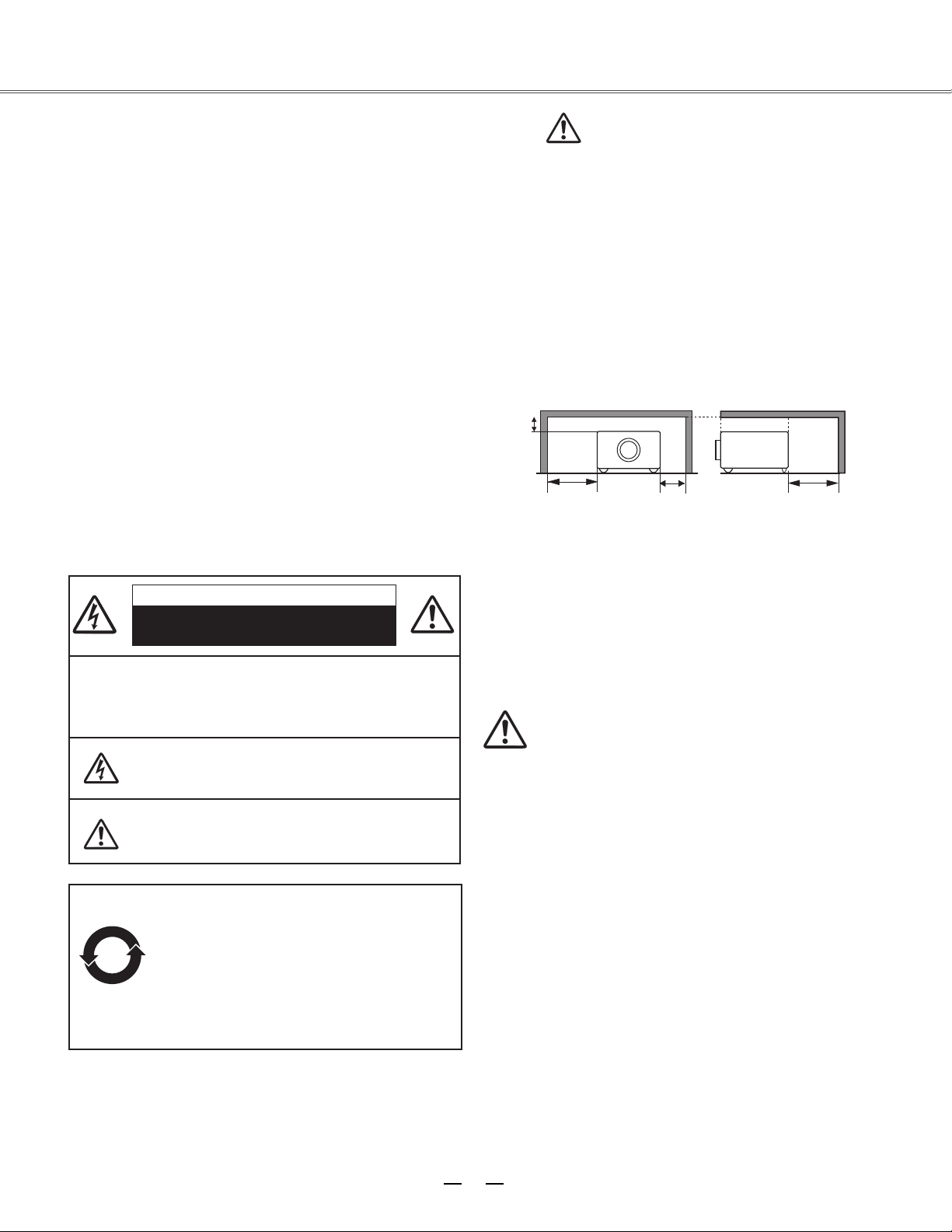
--Leave an appropriate space from the top, sides, and back
of the shell in order to ventilate and cool down the
projector. The figures below indicate the minimum
distance to be left. It must be satisfied if the projector is
placed in sealed environment like a cabinet.
Caution:
Please read this manual completely before installing and
operating the projector.
The projector provides many convenient features and
functions. Proper operation may enable you to fully utilize
the features and keep it in good condition. Otherwise, it
will not only shorten the service life of the unit, but also
may cause malfunction, a fire, or other accidents.
If your projector cannot work properly, please read this
manual again, check the operating methods and cable
connection, and try the solutions in the part of
Troubleshooting. If the problem still exists, contact the
dealer or the service center.
The lamp of the projector is a wearing part. The luminance
may decrease after a period of operation and be weaker
than that of a new lamp. This is normal. Please strictly
follow the steps in Turning on the unit and Turning off the
unit to turn on/off the projector, and the requirements in
Maintaining and cleaning the projector to service and clean
the projector regularly. Or the high temperature residual
heat may not radiate, greatly shortening the service life of
the projector and lamp, or even damaging them within a
short period.
Caution
Electric shock
Do not open
Caution: To reduce the risk of electric shock, do not
remove the cover (or back). No
user-serviceable parts inside except lamp
replacement. Refer servicing to qualified
service personnel.
The sign indicates the danger of high voltage,
i.e., electric shock.
The sign indicates important operating and
maintenance instructions in the manual with the
unit.
Environment-friendly use conditions: The
environment-friendly life time of the
projector and remote control is 10 years, the
lamp (consumable) 5 years, and the
provided batteries (consumable) 5 years.
The use conditions of the
environment-friendly use period are the
same with that of the product. Properly
operate and effectively maintain the
projector according to the requirements in
this manual.
Safety precautions
To the owner
Page 5

4
Safety guide
All the safety and operating instructions should be read
before the product is operated.
Read all of the instructions given here and retain them
for later use. Unplug this projector from AC power supply
before cleaning. Do not use liquid or aerosol cleaners.
Use a damp cloth for cleaning.
Fo l low all warnings and inst r uctions ma r ked on the
projector.
For added protection to the projector during a lightning
storm, or when it is left unattended and unused for long
periods of time, unplug it from the wall outlet. This will
prevent damage due to lightning and power line surges.
Do not expose this unit to rain or use near water... for
example, in a wet basement, near a swimming pool, etc...
Do not u se at t achm e nts n o t rec o mmen d ed by t he
manufacturer as they may cause hazards.
Do not place this projector on an unstable cart, stand,
or table. The projector may fall, causing serious injury
to a child or adult, and serious damage to the projector.
Us e only with a cart or s t a n d recommended b y the
manufacturer, or sold with the projector. Wall or shelf
mounting should follow the manufacturer’s instructions,
an d sh o u l d us e a mo u n t i ng kit app r o v ed by th e
manufacturers.
An appliance and cart combination
should be moved w ith care. Q uick
stops, excessive force, and uneven
surfaces may cause the appliance and
cart combination to overturn.
Slots and openings in the back and bottom of the cabinet
are provided for ventilation, to ensure reliable operation of
the equipment and to protect it from overheating.
The openings should never be covered with cloth or other
materials, and the bottom opening should not be blocked
by placing the projector on a bed, sofa, rug, or other
similar surface. This projector should never be placed
near or over a radiator or heat register.
This projector should not be placed in a built-in installation
such as a book case unless proper ventilation is provided.
Ne ver push objec ts of any kin d into this pr ojector
through cabinet slots as they may touch dangerous
voltage points or short out parts that could result in a
fire or electric shock. Never spill liquid of any kind on the
projector.
Do not install the projector near the ventilation duct of
air-conditioning equipment.
This projector should be operated only from the type
of power source indicated on the marking label. If you
are not sure of the type of power supplied, consult your
authorized dealer or local power company.
Do not overload wall outlets and extension cords as this
can result in fire or electric shock. Do not allow anything
to rest on the power cord. Do not locate this projector
where the cord may be damaged by persons walking on
it.
Do not attempt to service this projector yourself as
openi n g or remo v ing Cov e r s may ex p o se you t o
dangerous voltage or other hazards. Refer all servicing
to qualified service personnel.
Unplug this projector from wall outlet and refer servicing
to qualifie d service personne l under the fol l owing
conditions:
a. When the power cord or plug is damaged or frayed.
b. If liquid has been spilled into the projector.
c. If the projector has been exposed to rain or water.
d. If the projector does not operate normally by
following the operating instructions. Adjust only those
controls that are covered by the operating instructions
as improper adjustment of other controls may result
in damage and will often require extensive work by a
qualified technician to restore the projector to normal
operation.
e. If the projector has been dropped or the cabinet has
been damaged.
f. When the projector exhibits a distinct change in
performance-this indicates a need for service.
When replacement parts are required, be sure the
service technician has used replacement parts specified
by the manufacturer that have the same characteristics
as the original part. Unauthorized substitutions may
result in fire, electric shock, or injury to persons.
Upon completion of any service or repairs to this
projector, ask the service technician to perform routine
safety checks to determine that the projector is in safe
operating condition.
Page 6
10˚
10˚
10° 10°
10°
10°
5
Air circulation
Openings in the cabinet are provided for ventilation. To
ensure reliable operation of the product and to protect it
from overheating, these openings must not be blocked or
covered.
Caution
Hot air is exhausted from the exhaust vent. When using
or installing the projector, the following precautions
should be taken.
--Do not put any flammable objects, or spray can near
the projector. Hot air is exhausted from the air vents.
--Keep the exhaust vent at least 1 m away from any
objec
ts.
--Do not tou
ch a peripheral part of the exhaust vent,
especially screws and metallic part. This area will
become hot while the projector is being used.
--Do not put anything on the projector. Objects put on the
cabinet will not only get damaged but also may cause
fire hazard by heat.
Cooling fans are provided to cool down the projector.
The fan’s running speed is changed according to the
temperature inside the projector.
Air intake vent
Air intake vent
Exhaust vent
Air intake vent
Caution on ceiling mounting
For ceiling mounting, you need the ceiling mount kit
designed for this projector. When not mounted properly,
the projector may fall, causing hazards or injury. For
details, consult your dealer. The warranty on this
projector does not cover any damage caused by use of
any non-recommended ceiling mount kit or installation
of the ceiling mount kit in an improper location.
Safety guide
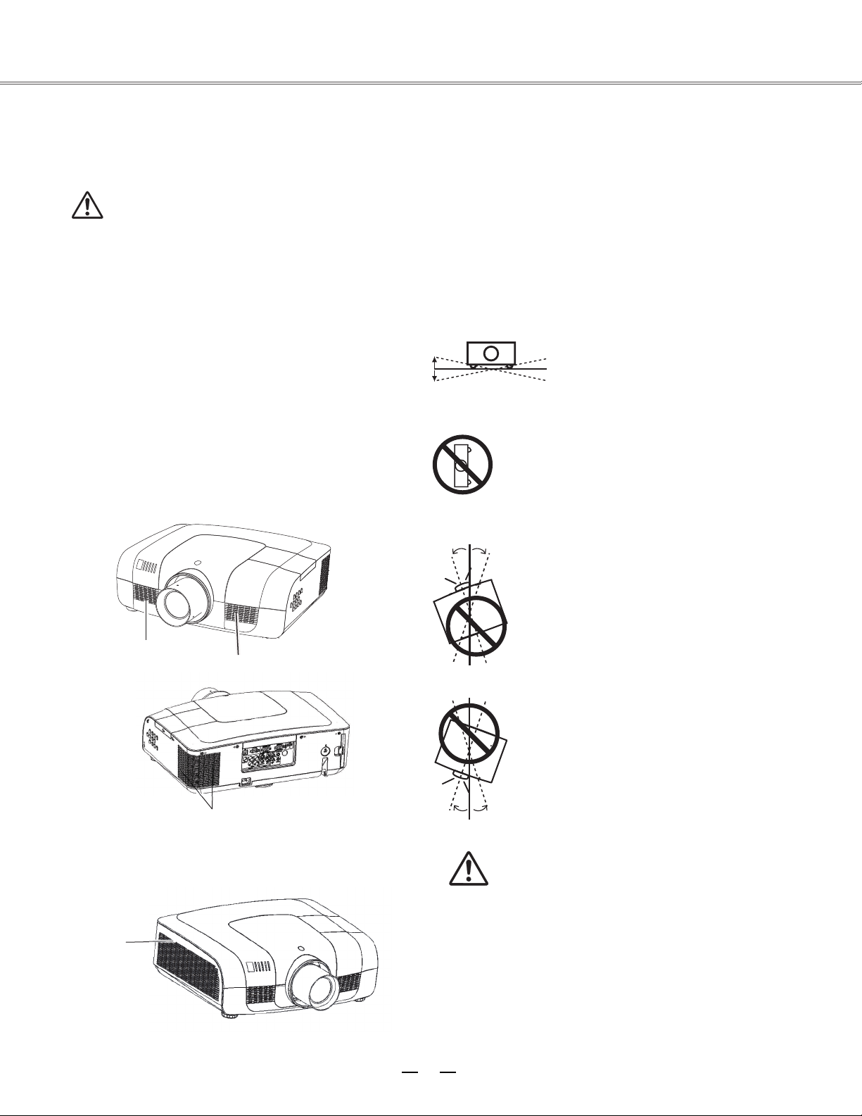
Installing the projector in proper directions
Install the projector properly for normal operation.
Improper installation may red
uce the lamp lifetime and
cause a fire hazard. The projector may project images
upward, downward, or slantwise when it is installed
vertically to the surface level. Keep the bottom of the
projector upward for installation when it is tilted
downward.
To flip an image, set the ceiling function ON.
Positioning precautions
Do not roll the projector over 10
degrees
from side to side.
Do not point the projector down to
projec
t an
ima
ge.
Do not roll the projector over 10 degrees from
side to side when projecting an image upward.
Do not tilt the projector over 10 degrees from
side to side when projecting an image downward.
Page 7
6
Safety guide
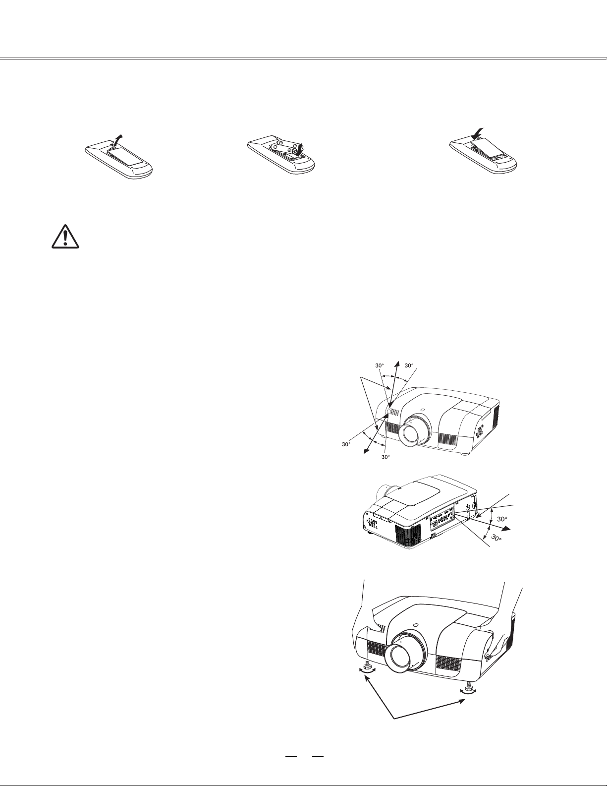
Moving the projector
Caution on lens protector
Before use, remove the lens protector. To move the projector, press and
hold the Shift or lens key more than 5 seconds to center the lens back.
Then, install the protector to protect the lens.
Lens protector
When moving the projector, retract the adjustable feet to prevent damage to the lens and cabinet.
Put it into a suitable case when the projector is not in use for a long period.
Caution in moving or transporting the projector
– Do not drop or bump the projector, otherwise damages or malfunctions may result.
– When carrying the projector, use a suitable carrying case.
– Do not transport the projector by courier or any other transport service in an unsuitable transport
case. This may cause damage to the projector. For information about transporting the projector by
courier or any other transport service, consult your dealer.
– Do not put the projector in a case before it is cooled enough.
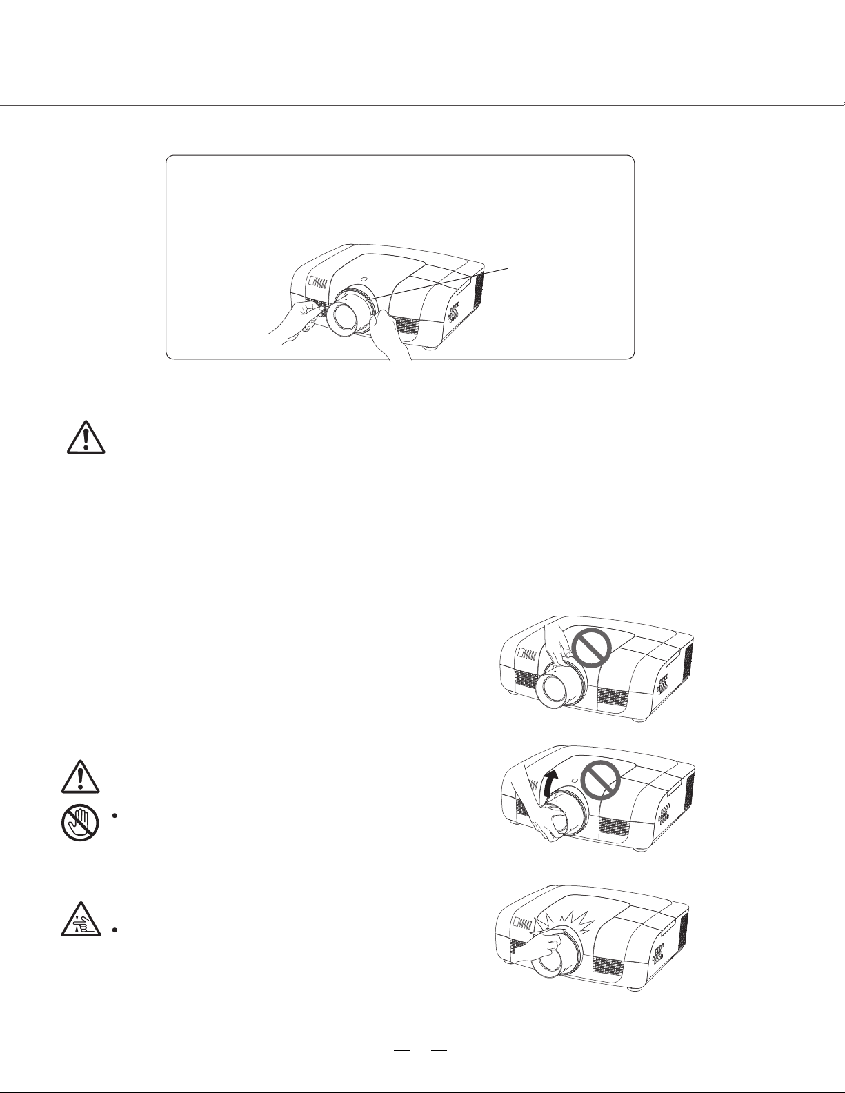
Caution in handling the projector
When lifting or moving the projector, do not hold the lens
or the directive hood to prevent damage to the lens or the
unit.
Handle the projector with care. Do not drop or bump it to
avoid strong force, or place other objects on the cabinet.
Caution
The lens of the projector is electric.
When operating the projector, pay
attention to the following conditions.
When the lens is rotating, do not
touch it, otherwise your fingers may
get hurt.
Do not allow a child to touch the lens.
Do not hold the lens and the peripheral part.
Page 8
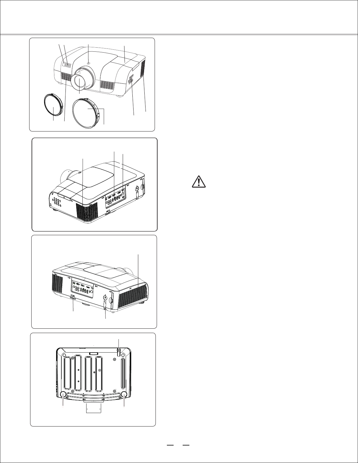
Part names and functions
②
Front
⑧
⑤
④
①
⑥
⑦
③
⑩
⑨
(1) Lens release button
(2) Indicator
(3) Lamp cover
(4) Speaker
(5) Lens cap
(6) Projector lens
(7) Decorative cover
(8) Remote receiver (Front & top)
(9) Side control panel
Back
Back
⑭
⑫
⑩
⑪
(10) Exhaust vent
Caution
Hot air is exhausted from the exhaust vent. Do
not put heat-sensitive objects near this side.
⑬
(11) Remote receiver (Back)
(12) Terminals and connectors
(13) Air filter and air-intake vent
(14) Power cord connector
⑮
Bottom
⑯
⑮
(15) Safety lock
(16) Adjustable feet
⑯
7
Page 9
7
10
9
8
6
11
1
54
32
HDMI
INPUT2
INPUT1
MONITOR OUT
SCART IN
COMPUTER IN2 COMPUTER IN1
3/4
HS/CS
VS
OUT
4
VIDEO 2
1
8
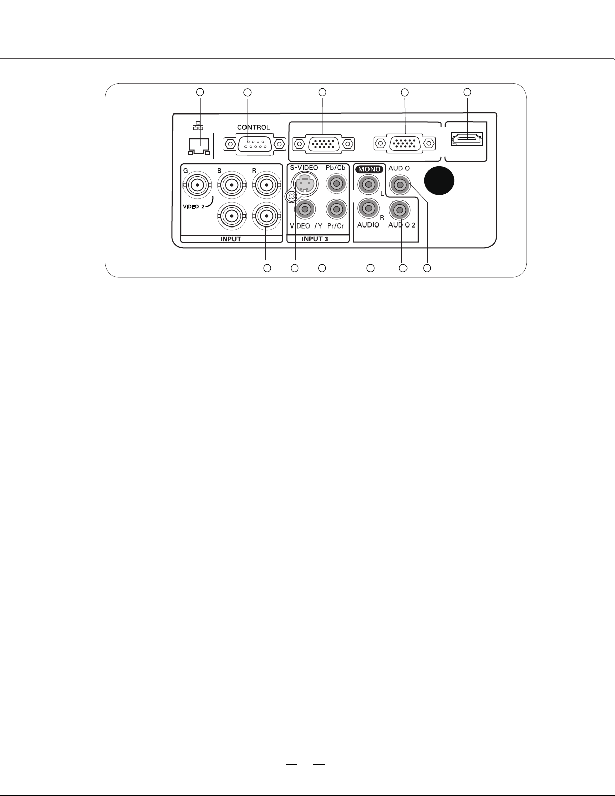
(1) Network port
Used to connect the network cable.
(2) CONTROL
When using RS232 to control the projector,
please connect the serial control line to this
terminal.
(3) COMPUTER IN2/MONITOR OUT
- Used to connect the computer output.
- Used to output the analog signals from (4) or
(6) to the other monitor.
(4) COMPUTER IN1/SCART IN
- Used to connect a computer or RGB SCART
output.
(5) HDMI
Used to connect the HDMI digital output.
(6) BNC input jacks
Connect the component or composite video
output from video equipment to VIDEO 2
te
rminal, or connect the RGBHV format (5
line system) signal to G, B, R, Hs, and Vs
jacks.
(7) S-VIDEO
Used to connect the SVIDEO output of video
equipment.
(8) Component (video) input jacks
Connect the component signals to these
terminals or connect the component video
signal to VIDEO 1/Y terminal.
(9) AUDIO 3/4
Used to connect the audio output from vide
equipment (INPUT 3 or INPUT 4). When the
audio output is monaural, connect it to L
(MONO) jack.
(10)
AUDIO
2
Connect the audio output from video
equipment connected to (3) or (4) to this jack
(stereo).
(11) AUDIO OUT
Used to connect the audio output (stereo)
connected to (9) or (10).
Part names and functions
Rear terminal
Rear terminal
Page 10
⑤
⑦
⑨
⑩
⑪
⑫
⑬
⑥
⑧
①
②
④
③
9
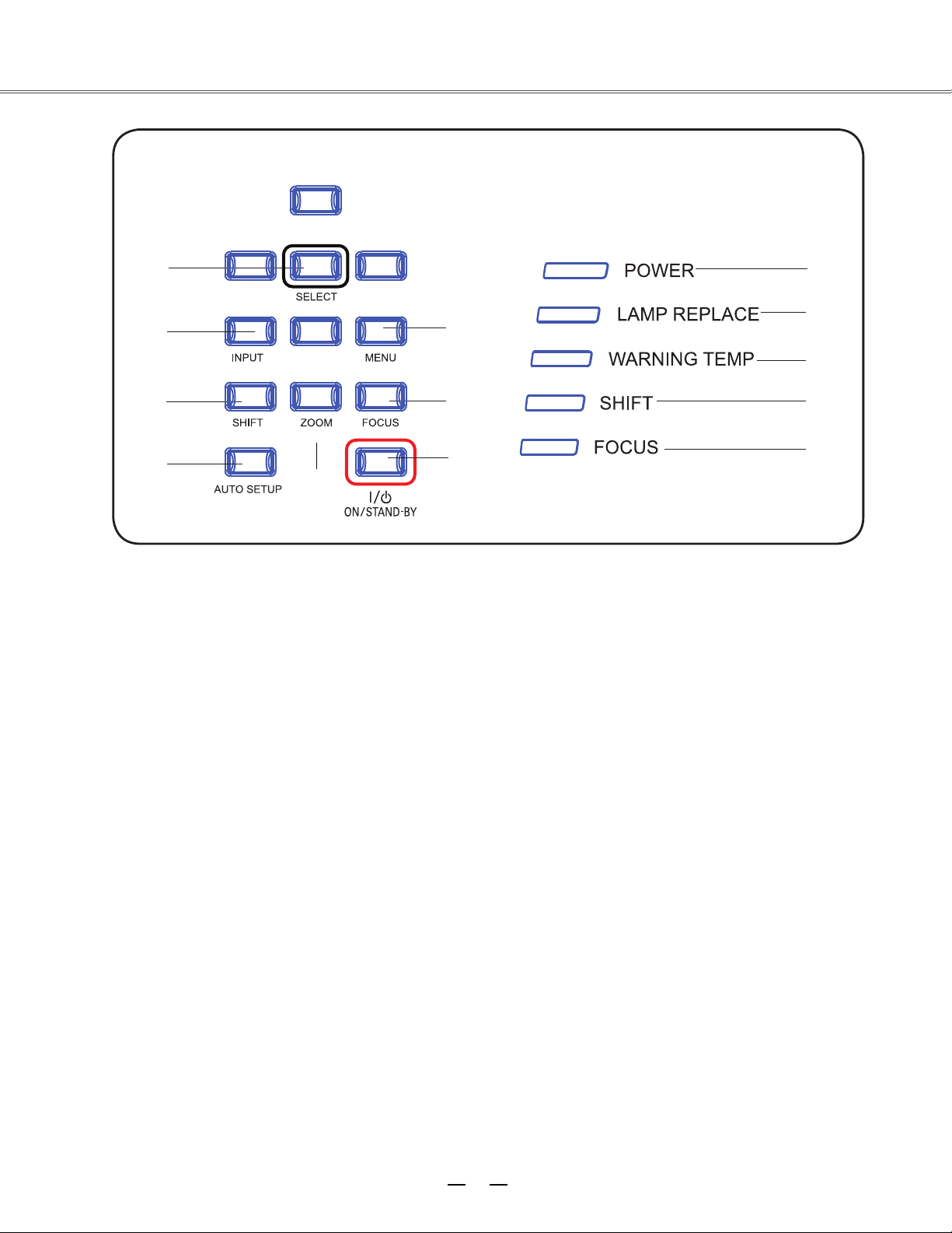
(1) SELECT button
To select the lens shift function.
(2) INPUT button
To select an input source.
(3) SHIFT button
To enter the lens shift mode.
(4) AUTO SETUP button
To perform various settings configured
automatically, including the input source
search function and auto adjusting function.
(5) ZOOM button
To zoom in/out images.
(6) MENU button
To open or close the screen menu.
(7) FOCUS button
To adjust the focus.
(8) ON/STAND-BY button
(9) POWER indicator
– Lights red when the projector is in stand-by
mode.
– Lights green during operations.
– Flashes green in the Power control mode
(10) LAMP REPLACE indicator
It turns orange when the life of the projection
lamp draws to an end.
(11) WARNING TEMP indicator
It flashes red when the internal projector
temperature is too high.
(12) SHIFT indicator
It lights blue when the projector lens is
moving.
It lights blue when the projector lens is
moving to the end.
(13) FOCUS indicator
It lights green when zooming in/out.
To turn on/off the projector.
Part names and functions
Side control and indicators
Side control
Indicators (Top panel)
Page 11
①
②
③
⑤
⑥
⑦
⑧
⑨
⑩
⑪
⑫
⑬
⑮
⑭
⑯
⑰
④
⑱
⑲
25
26
27
28
29
⑨
S.MENU
⑦
⑪
⑩
⑬
⑫
⑮
⑭
⑧
F.MENU
▲▼◄►(
VOLUME
– / +)
⑤
VIDEO 1
① ON-STANDBY
② HDMI
③ COMPUTER
⑥
VIDEO 2
④ RGBHV
10
TIMER
KEYSTONE
SELECT
SCART
COMPONENT
S-VIDEO
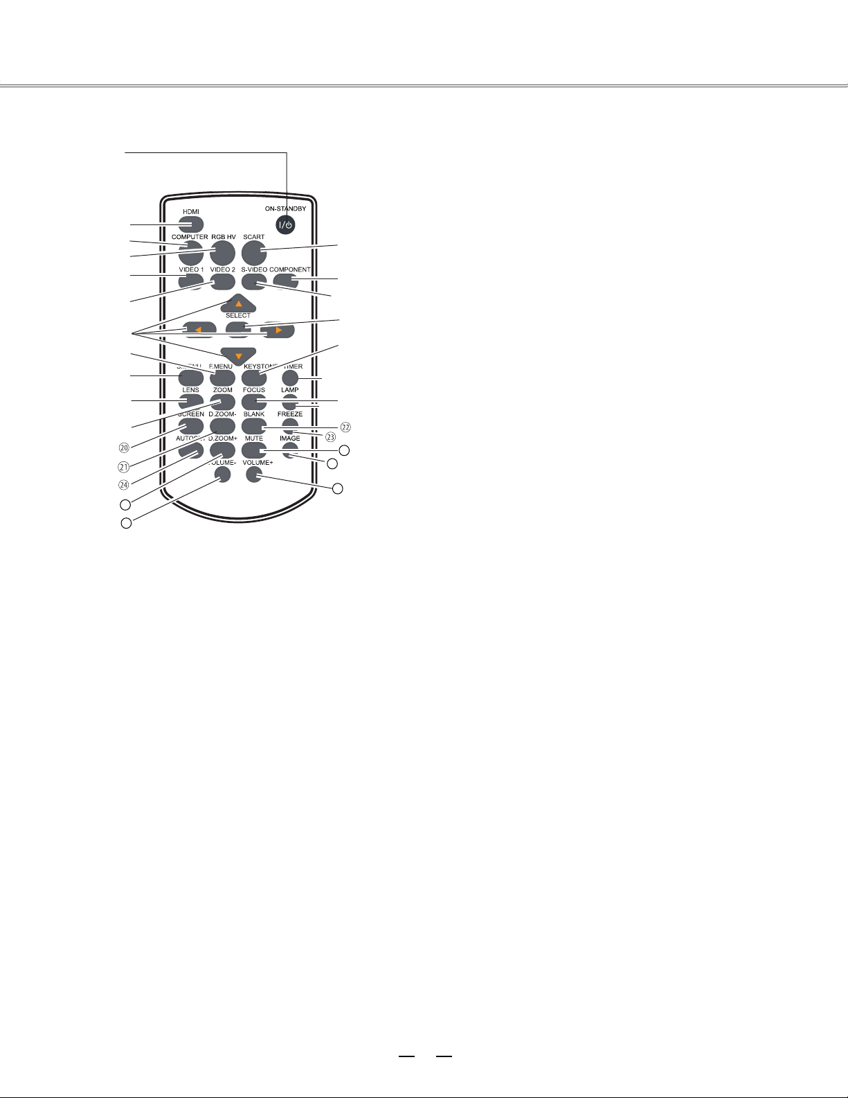
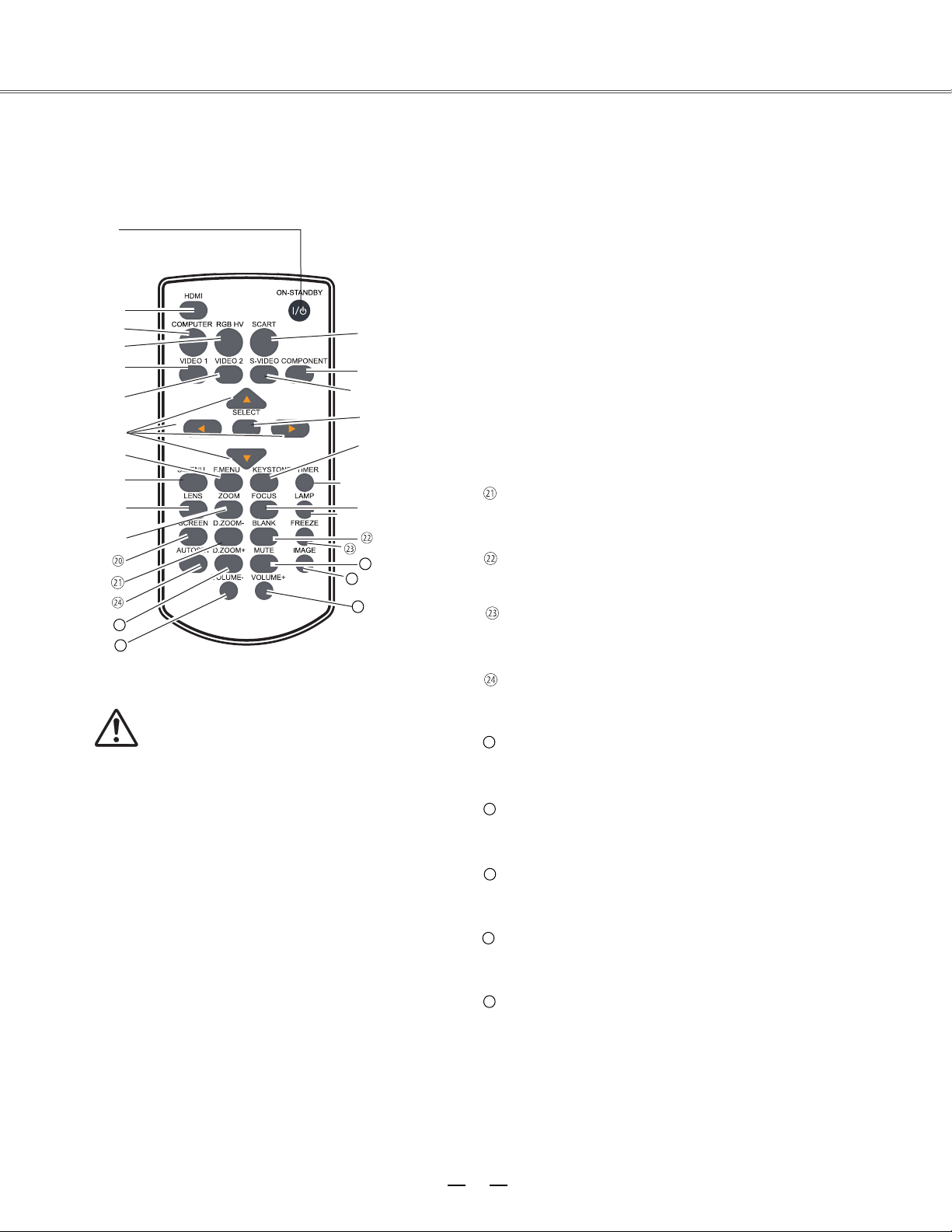
Part names and functions
Remote control
Turn the projector on or off.
button
Select HDMI input source.
Select VGA1 or VGA2 input source.
Select RGBHV input source.
Select VIDEO 1 input source.
Select VIDEO 2 input source.
Open or close the full screen menu.
Open or close the shortcut menu.
button
button
button
button
button
button
button
button
button
button
button
button
button
– Select an item or adjust the value in the
on-screen menu.
– Pan the image in Digital zoom + mode.
– Adjust the volume level (
◄►)
.
button
Select SCART input source.
Select the component input source.
Select the S-Video input source.
-Access the full menu or select an item in the
menu.
Calibrate keystone type distortion.
Enable the timer function.
Page 12
11
MUTE
BLANK
FREEZE
IMAGE
LAMP
FOCUS
VOLUME+
⑳
⑱
⑰
⑯
VOLUME-
⑲
25
26
29
28
27
ZOOM
LENS
SCREEN
D.ZOOM+
AUTOSET
D.ZOOM-
①
②
③
⑤
⑥
⑦
⑧
⑨
⑩
⑪
⑫
⑬
⑮
⑭
⑯
⑰
④
⑱
⑲
25
26
27
28
29
Select the lens shift mode.
Zoom in/out images.
Select a screen display mode.
Select the digital zoom - mode.
Enter the AUTOSET mode.
Select the digital zoom + mode.
Decrease the volume level.
Adjust the focus.
Select the lamp mode.
Temporarily close the on-screen image.
Freeze the projected image.
Select the image mode.
Mute the sound.
Increase the volume level.
button
button
button
button
button
button
button
button
button
button
button
button
button
button
To ensure safe operatio
n, observe
the following precautions:
– Do not bend, drop, or expose the remote
control to moisture or heat.
– For cleaning, use a soft dry cloth. Do not
apply benzene, thinner, splay, or any other
chemicals.
Part names and functions
Remote control
Page 13
12
●
●
●
●
●
●
●
●
1 2 3
5M
5M
To ensure safe operation, please observe the following precautions:
Use two (2) AAA or LR03 type alkaline batteries.
Always replace batteries in sets.
Do not use a new battery with a used battery.
Avoid contact with water or liquid matter.
Do not expose the remote control to moisture or heat.
Do not drop the remote control.
If the battery has leaked on the remote control, carefully
wipe the case clean and install new batteries.
Risk of explosion if a battery is replaced by an incorrect
type.
Dispose of used batteries according to the instructions.
Operating range
Point the remote control toward the projector when pressing any
button. The maximum operating range for the remote control is
about 5 meters and 60 degrees.
Adjustable feet
Projection angle can be adjusted up to 5.0 degree with the
adjustable feet.
Rotate the adjustable feet to lift the projector to a certain height.
During lifting, rotate the two feet clockwise.
To lower or retract the adjustable feet, rotate the two feet
counterclockwise.
Keystone distortion of the projected image can be corrected by
menu operation.
Adjustable feet
●
Part names and functions
Remote control battery installation
Open the battery
compartment lid.
Install new batteries into the
compartment.
Replace the compartment
lid.
For correct polarity
(+ and –), be
sure
battery terminals are in
contact
with pins in the
compartment.
Page 14
13
50%
10%
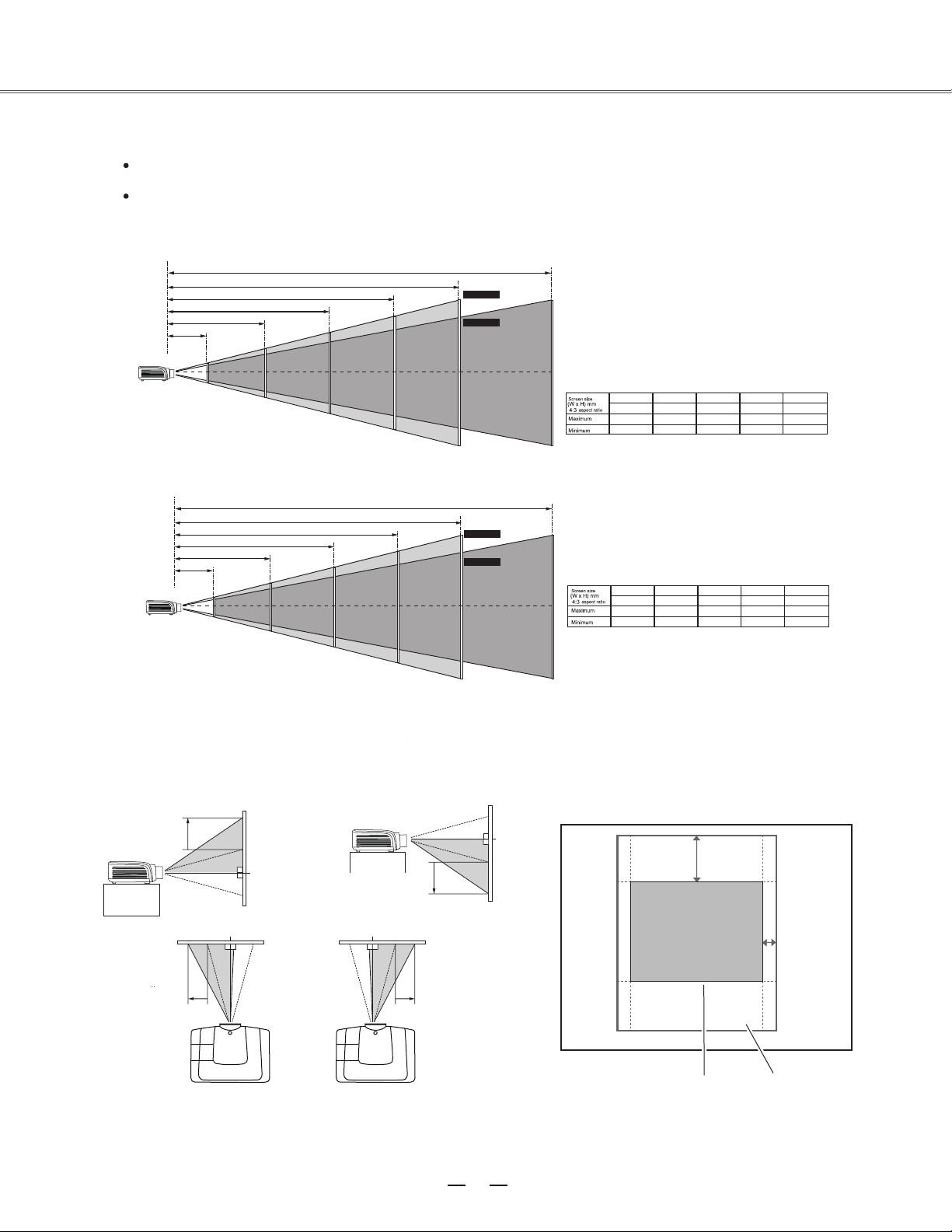
Installation
Positioning the projector
Note
The brightness in the room has a great influence on picture quality. It is recommended to limit the ambient lighting
in order to get the best image.
All measurements are approximate and may vary from the actual sizes.
√
Lens shift adjustment
Projection lens can be moved from side to side and up an
function makes the positioning of images easy on the screen.
The display
position can be
shifted upward up
to 50% elevation
of the display.
The display
position can be
shifted downward
up to 50%
elevation of the
display.
When the lens is shifted to top. When the lens is shifted to bottom.
When the lens is shifted to leftmost. When the lens is shifted to rightmost.
The display
posit
ion can be
shifted to the left
up to 10% width
of the display.
The display position can
be shifted to the right up
to 10% width of the
display.
Adjusting range
Shifting range
When the lens is
shifted to the center.
E1655 series
40”
813 x 610
1.024 m
1.705 m
100”
2032 x 1524
2.628 m
4.334 m
200”
4064 x 3048
5.301 m
8.716 m
300”
6096 x 4572
7.974 m
13.098 m
400”
8128 x 6096
10.647 m
17.481 m
17.481 m
400”
400”
E1655W series
40”
862 x 539
1.093 m
1.777 m
100”
2154 x 1346
2.8 m
4.514 m
200”
4308 x 2692
5.645 m
9.077 m
300”
6462 x 4039
8.489 m
13.64 m
400”
8616 x 5385
11.319 m
18.187 m
11.319 m
18.187 m
2.8 m
5.645 m
8.489 m
2.628 m
5.301 m
7.974 m
10.647 m
Diagonal
( )
Max. frame
Min. frame
Diagonal
( )
Max. frame
Min. frame
Page 15

HDMI
INPUT2
INPUT1
MONITOR OUT
SCART IN
COMPUTER IN2 COMPUTER IN1
3/4
HS/CS
VS
OUT
4
VIDEO 2
1
14
G B R H V
•
•
•
•
Installation
Connecting to computer (Digital and analog RGB)
Cables used for connection ( =Cables are not supplied with the projector.)
VGA cable (1)
Serial crossover cable (F-F) *
BNC cable *
HDMI cable *
Monitor output Serial output Monitor input * Monitor output HDMI terminal
BNC cable Serial crossover
cable VGA cable VGA cable HDMI cable
Control terminal Anal
og output Analog input HDMI
Unplug the power cords of both the projector and external
equipment from the AC outlet before connecting
the cables.
Page 16
15
HDMI
INPUT2
INPUT1
MONITOR OUT
SCART IN
COMPUTER IN2 COMPUTER IN1
3/4
HS/CS
VS
OUT
4
VIDEO 2
1
•
•
•
•
Unplug the power cords of both the projector and external equipment from the
AC outlet before connecting
the cables.
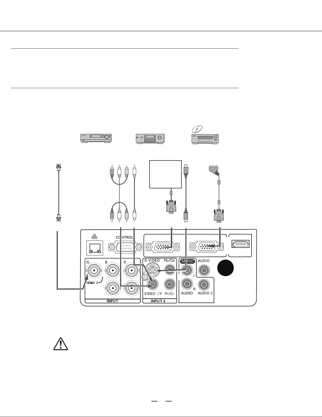
Installation
Connecting to video equipment
Cables used for connection (*=Cables are not supplied with the projector.)
Video cable (RCA* 1 or RCA*3) *
BNC cable (BNC*1 or BNC*3) *
S-Video cable *
Scart-VGA cable *
Composite
video
Component
video
output
Composite
video
S-Video
outp
ut
RGB Scart 21-pin
output
RCA cable S-Video cable Scart-VGA cable
Video Y-Pb/Cb-Pr/Cr
Video
Analog
otput
S-VIDEO Analog
input
Refer to the
analog outpu
signal table as
shown in the
figure above.
Page 17
3/4
OUT
1
16
(R) (L)
(R) (L)
(R) (L)
or
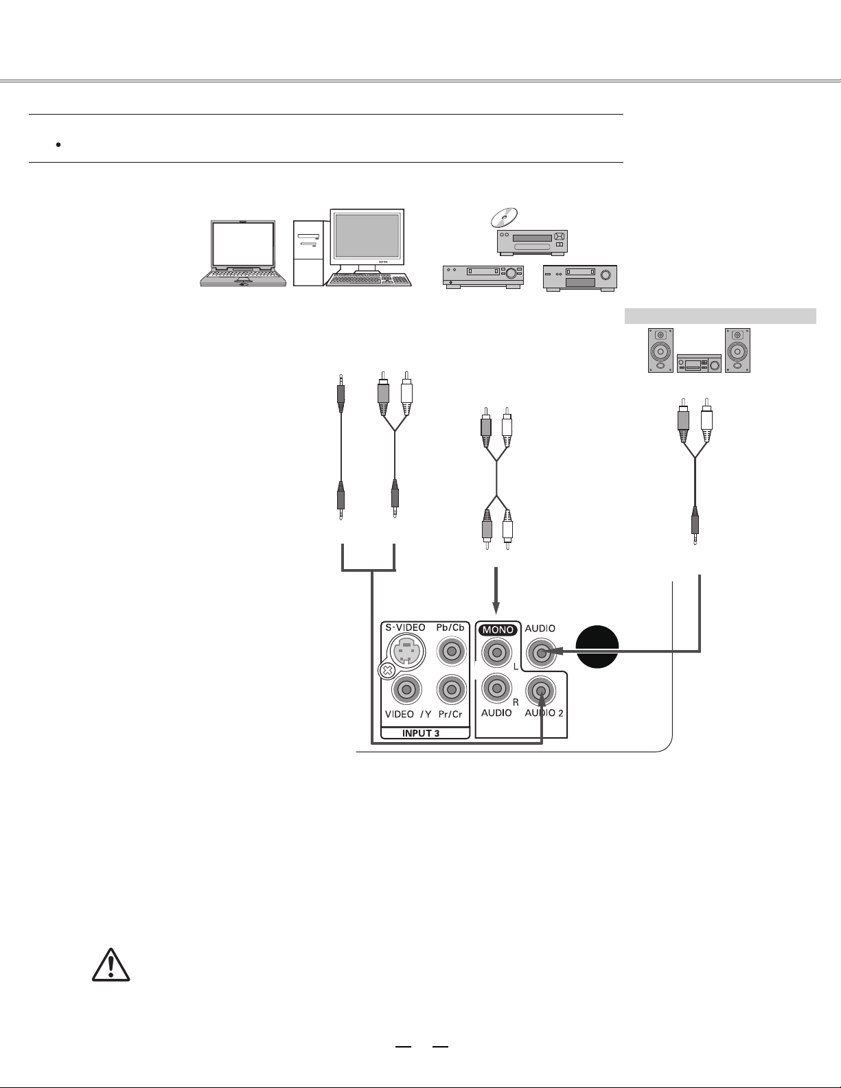
Unplug the power cords of both the projector and external
equipment from the AC outlet before connecting
the cables.
Installation
Connecting to audio equipment
Cables used for connection (* =Cables are not supplied with the projector.)
Audio cable *
External audio equipment
Audio cable
Audio cable
(Stereo)
Audio output
Audio input
(Stereo)
Audio cable
Audio output
Audio cable
(Stereo)
Audio cable
(Stereo)
Audio IN
Page 18

17
Note:
Using incorrect power cord may influence the product performance, or even cause hazards like an electric shock
or fire. To ensure the product performance and security, please apply the cable of the same model with the original
one.
Common connecting cables include the AC power cord, vari ous VGA cables, audio cable,
video cable, and serial
control cable.
Installation
Connecting to the AC power cord
This projector uses nominal input voltages of 100–240 V AC
correct input voltage. It is
designed to work with a single-phase power system having a
duce the risk of electrical
shock, do not plug into any other type of power system. If
you are not sure of the type of power being supplied, consult
service station. Connect the
projector with all peripheral equipment before turning it on.
Connect the AC power cord
(supplied) to the projector.
The AC outlet should be near this equipment and must be easily accessible.
Note:
Note on the power cord
AC power cord must meet the requirements of the country where you use the projector.
Confirm the AC plug type with the chart below and proper AC power cord must be used.
If the supplied AC power cord does not match
Projector side
AC outlet side
To power cord connector
on your projector.
Ground
To the AC outlet.
(100-240 V AC)
and it automatically selects the
grounded neutral conductor. To re
your authorized dealer or
Unplug the AC power cord when the projector is not in use. When the
projector is connected to an outlet with AC power cord, it is in stand-by
mode and consumes a little electric power.
Page 19
18
1
2
3
●
●
●
1
3
2
Installation
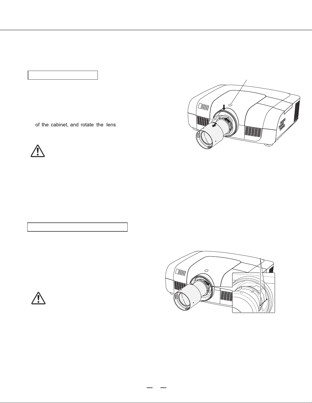
Lens installation
Follow the instructions below to install the lens upon replacing or using the provided lens. For the specification of
projector lens, contact your dealer.
Removing the lens
Lens release button
Shift the lens to the center with the lens shift
function.
Turn off the projector, and unplug the AC power
cord.
Press and hold the lens release button on the top
counterclockwise
until the lens cannot be rotated.
Draw it out slowly from the projector.
Caution
Do not drop the lens when handling.
Installing the lens
Remove the lens decorator.
Align the red point on the lens with that on the
projector to install the lens.
Rotate the lens clockwise slowly until it clicks.
Make sure that the lens is
the projector.
Caution
While installing the lens, do not hold the release button.
Notes on lens installation
Do not touch or remove any part except lens and its relative part. This may cause a malfunction, electric shock,
fire or other hazards.
Make sure the mode of the lens is compatible with your projector before installing or replacing the lens.
For information about the lens and its installation, contact the local dealer.
Red point
Page 20

19
Basic operation
Caution on handling the PIN code
If you forget your PIN code, the projector
can no longer be started. Take a special
care in setting a new PIN code; write
down the number in a column on page 59
of this manual and keep it at hand. Should
the PIN code be missing or forgotten,
consult your dealer or service center.
Turning on the projector
1 Complete peripheral connections (with a computer, VCR, etc.) before
turning on the projector.
2
Connect the projector’s AC power cord into an AC outlet. The
POWER indicator turns red. Open the lens cap.
3 Press the ON/STAND-BY button on the top control or on the remote
control. The POWER indicator becomes green and the cooling fans
start to operate. The preparation display appears on the screen and the
count down starts.
4
If the projector is locked with a PIN code, a PIN code Input Dialog
Box appears. Enter the PIN code as instructed below.
Note:
When the logo select is set to be "Off,” the
logo will not be displayed on the screen.
When the
Display function is set to be
"Off,”
the logo
and countdown will not be displayed on the screen.
During the countdown period, all operations are
invalid except shutdown.
Enter a PIN code
Select a number by pressing the
▲▼
buttons,
and then press the
►
button to fix the number
and move the cursor. The number changes to "*".
If you fixed an incorrect number, move the cursor
to the number you want to correct by pressing the
◄
button, and then select the correct number by
pressing the
▲▼
buttons.
Repeat this step to complete entering a three-digit
number.
After entering the three-digit number, move the
cursor to "Set", then you can start to operate the
projector.
If you entered an incorrect PIN code, the "PIN
code" and the number (***) turn red. Enter the
correct PIN code all over again.
What is PIN code?
PIN (Personal Identification Number) code is a security code that
allows the person who knows it to operate the projector. Setting the
PIN code prevents unauthorized use of the projector.
A PIN code consists of a three-digit number. Refer to the PIN code
lock function in the Setting Menu on pages 46 for locking operation
of the projector with your PIN code.
Move the cursor to Set, and press SELECT.
Page 21

20
1
2
3
Basic operation
Turning off the projector
Press the ON/STAND-BY button on the side control or on
the remote control, and “Power off?” appears on the screen.
Press the ON/STAND-BY button again to turn off the
projector. The POWER indicator starts to flash red, and the
cooling fans keep running. (You can select the level of the
fans’ quietness and running speed.) At this time you can
unplug the AC power cord even if the fans are still running.
When the projector has cooled d
own enough to be turned on
again,
the POWER indicator stops flashing.
“Power off” disappears after 4 seconds.
To maintain the lamp life, once you turn the
projector on, wait at least 5 minutes before turning if off.
Do not operate the projector continuously without
reset. Continuous use may result in shortening the lamp life.
Turn off the projector and let it stand for about an hour in
every 24 hours.
Note:
When the On start function is “On,” this projector is turned on automatically by connecting the AC power cord
to an AC outlet (p. 40).
The running speed of cooling fans is changed accor ding to the temperature inside the projector.
Do not put the projector in a case be fore the projector is cooled enough.
If the WARNING indicator flashes or emits a red light, see “Warning Indicator”.
While the POWER indicator is flashing, the lamp is being cooled down and the projector cannot be turned on.
Wait until the POWER indicator turns red to turn on the projector again.
The fan rotation will terminate directly if the AC power cord is unplugged immediately after the projector is
turned off.
The projector can be turned on after the POWER indicator turns red. The waiting time to restart will be
shortened when the normal power-off processing for fan cooling is completed, comparing with the time the AC
power cord is immediately unplugged after the power-off.
Power off ?
Page 22

How to operate the on-screen menu
The projector can be adjusted or set via the on-screen
menu, including Shortcut menu and Full menu.
General operations are available via the shortcut menu.
A full menu features multiple structures. Each main
menu can be divided into several levels of submenus,
and submenus are also divided into several levels of
sub-submenus. For each adjustment and setting
procedure, refer to the respective sections in this
manual.
Short Cut menu
Remote control
Basic operation
Indicators
Select button
button
Full menu button
Press the menu button on the side control or the S.MENU button on the remote control to display the shortcut
1
menu.
2
Press the
Press the menu button on the side control or the S.MENU button on the remote control again to quit the shortcut
3
menu. Or press the SELECT button again to show the full menu.
buttons to select a menu entry. Press the
▲▼
buttons to adjust settings.
◄►
Full menu
1
Press the menu button on the side control to display
the shortcut menu, and then the SELECT button
again to show the full menu
pre
ss the F.MENU button to show it.
Press the buttons to select an entry in the
2
main menu and then press
to access the
3
Press the
entry, and then press SELECT or the
set or enter the submenu.
4
Press the
switch among the entries. Press the SELECT button
for corresponding operation and then return to the
submenu.
◄►
submenu.
buttons to select your required
▲▲▼▲▼◄►
buttons to adjust settings or
. Or you may directly
the select or button
▼
►
button to
Full menu
Press the
5
Pr
ess the F.MENU on the remote control again to
quit the full menu mode.
button to return to the previ
ous menu.
21
Page 23

22
③ ④ ⑤ ⑥ ⑦ ⑧ ⑨① ②
Basic operation
Full menu bar
(1) PC adjust menu
Used to adjust parameters, like 、 、 、 、
、 、 , to match with VGA input signal format.
(2) Screen menu
If a computer is selected as a signal source, the following setup options for the image size are available: Normal, True,
Wide, Full, Custom,
or keystone.
Digital zoom +/If video equipment is selected as a signal source, the following setup options for the image size are available: Normal,
Wide,
or keystone.
Custom
(3) Image select menu
The available image m
odes
are: Dynamic, Normal, Cinema, Blackboard (Green), Colorboard, or User Image.
(4) Image adjust menu
If a computer is selected as a signal source, the following image adjusting options are available: Contrast, Brightness,
Color temp, Red,Green,Blue, Sharpness, and Gamma.
If video equipment is selected as a signal source, the fo llowing image adjusting options are available: Contrast,
Brightness, Color , T i n t , Red,Green,Blue, Sharpness, Gamma, Noise reduction, and
Progressive.
(5) Input
menu
Used to select
input source, HDMI,
Computer
1
, Computer 2, Component, Video 1, Video 2, S-Video, RGBHV or SCART.
(6) Sound menu
Used to adjust the volume level or mute the sound.
(7) Setting menu
Used to configure the projector operation settings.
Advanced setting menu
Used to configure the projector operation settings.
(8)
Network menu
Used to access the network function.
(9)
(
10
)
Information menu
Used to display information.
Main menu
Sub menu
Auto PC adj. Fine sync Total dots Horizontal、 Vertical、 Clamp、D i s p l a y a r e a H
D i s p l a y a r e a V Reset Mode free 、 Store
10
Page 24

23
Basic operation
Auto setup function
This function is available just by pressing the Auto Setup
button on the top control. The system then automatically
performs various settings in the setup menu, including input
search, and auto PC adj.
Arrow keys
Keystone
button
Auto setup
Remote control
▲▼
Lens shift Control panel (on the right side of the projector body)
1.Use SHIFT on the control panel or LENS of the remote control to adjust the lens.
2. “Lens shift” will jump out on the screen. According to the instruction, please use
▲▼◄► to move the image to the desired place without causing image
distortion. The maximum shift range is ±50°vertically and ±10°horizontally.
3.Push SHIFT on the control panel or LENS of the remote control and hold on for
at least 5 seconds to reset the lens to the center
Note:
•when the lens is in unshifted, the arrows turn green.
•when the lens is shifted, the arrows turn yellow
•when the lens reaches its maximum shift range, the arrows turn red.
Zoom adjustment
1.Push ZOOM on the control panel or ZOOM of the remote control to
enter zoom adjustment.
2. “Zoom” will jump out on the screen. According to instruction, please
use▲ ▼ to zoom in or zoom out.
Focus adjustment
1.Push FOCUS on the control panel or FOCUS of the remote control
to enter focus adjustment.
2. “Focus” will jump out on the screen. According to instruction, please
use▲ ▼ to adjust the focus.
Zoom+
button
button
Shift
LENS
Page 25

24
●
●
●
●
●
The arrows are white when there is
no correction.
The
direction of the arrows which
are being corrected turns red.
maximum correction.
button on the top control or on the
remote control once more while the
keystone dialog box is being
displayed, the keystone adjustment
is canceled.
The adjustable range can be limited
dependin on the input signal.
Keystone
If a projected picture has keystone distortion, correct the image
with the Keystone function.
Press the KEYSTONE button on the top control or on the
remote control. The keystone dialog box appears. Correct
keystone distortion with the arrow buttons
▲▼ . Keystone
adjustment can be stored.
Reduce the upper
width with
the
▲ button.
Reduce the lower
width with the
▼ button.
Sound adjustment
Direct operation
Volume
Press the VOLUME+/– buttons on the side control or on
the remote control to adjust the volume.
Remote control
Mute
Press the MUTE button on the remote control and select
ON to turn off the sound temporarily. To restore the sound
to its previous level, press the MUTE button again or press
the VOLUME+/– buttons. Mute function is also effective
for AUDI
O OUT jack.
Volume –
button
Sound menu
Full menu operation
1. Press the F.MENU button to display the full screen
menu. Use the
▲
▲
▲
▲
▲
▲
buttons to move the cursor to
the Sound Menu icon. Press SELECT or the
button to enter the submenu entry.
2. Use the
▲▼
▼
buttons to move the cursor to the
desired item.
Volume
Press the button to increase the volume; press the
button to decrease the volume.
Mute
Press the buttons to switch the mute function.
To restore
the sound, press the Volume +/- button.
Mute button
Volume+
button
Basic operation
Page 26

25
Basic operation
HDMI
Computer
button
Video button
D.ZOOM+/-
S-Video
button
Component
button
Arrow buttons
▲▼
Lamp mode
button
Freeze
Remote control operation
Using the remote control for some frequently used operations is advisable. Just pressing one of the buttons enables
you to make the desired operation quickly without calling up the on-screen menu.
Remote control
COMPUTER/VIDEO/S-VIDEO/COMPONENT button
Press the Computer/video/HDMI/S-Video/RGBHV/SCART
/component button to select an input source.
FREEZE button
Press the FREEZE button to freeze the picture on the screen. To
cancel the Freeze function, press the FREEZE button again or
press any other button.
D.ZOOM button
Press the D.ZOOM button and use the ▲▼ buttons to access
the digital zoom mode.
LAMP button
Press the LAMP button to select the lamp mode to change the brightness of
the screen.
Normal … Normal brig htness
Auto …… Brightness changes according with the input signal, providing the
contrast of images and thus more real images.
Eco …… Lower brightness reduces the lamp power consumption and
extends
the la
mp life.
√ Note:
See the next page for the
description of other buttons.
Page 27

26
02
:
02
Basic operation
LENS button
ZOOM button
Screen mode
button
Timer button
Focus button
Blank button
button
BLANK button
Press the BLANK button to black out the image. To restore to
normal, press the BLANK button again or press any other
button. The screen changes each time you press the button as
follows.
Black out →Normal →Black out →Normal...
“Blank” disappears after 4 seconds if
there is no other button operation.
TIMER button
Press the TIMER button. The timer display “00:00” appears on the
screen and the timer starts to count time (00:00–59:59).
To stop the Timer, press the
T
IMER button. Press the TIMER
button again, and then the Timer display disappears.
Timer display
IMAGE button
Press the IMAGE button on the remote control to
select your required image mode.
SCREEN button
Press the SCREEN
button on the remote control to
select your required screen mode.
LENS button
Press the LENS button on the remote control to adjust the lens
position.
√Note:
See the previous page for
the description of other
buttons.
ZOOM button
Press the ZOOM button on the remote control to zoom in/out images.
F
OCUS button
Press the FOCUS button on the remote control to adjust the focus of images.
Blank
Page 28

27
VGA 1
VGA 2
1
2
HDMI
VGA 1
VGA 2
RGBHV
SCART
Computer input
Input source selection (VGA1/VGA2)
Direct operation
Press the INPUT button on the side control or the COMPUTER
button on the remote control to select either VGA1/VGA2.
Remote control
Input menu
Full menu operation
Press the F.MENU button to display the full
screen menu. Use the buttons to select the
input source icon and press the
►
►
►
button or
SELECT button.
Press the ▲▼ buttons to select VGA1or VGA2,
and then press the SELECT button.
COMPUTER button
F.MENU button
Component
S-Video
Video1
Vi
deo2
Page 29

28
RGBHV
HDMI
VGA 1
VGA 2
RGBHV
SCART
Computer input
Input source selection (RGBHV)
Direct operation
Press the INPUT button on the side control or the COMPUTER
button on the remote control to select RGBHV.
Remote control
Input menu
Full menu operation
1. Press the F.MENU button to display the full screen
menu. Use the
▲▼ buttons to select the input
source icon and press the
► button or SELECT
button.
2. Press the ▲ ▼ buttons to select RGBHV, and
then press the SELECT button.
RGBHV button
F.MENU button
Component
S-Video
Video1
Video2
Page 30

29
Auto
-----
Computer input
Computer system selection
The projector automatically tunes to various types of computers with its function of Multi-scan system and Auto PC
Adjustment. If a computer is selected as a signal source, the projector automatically detects the signal format and
tunes to project proper images without any additional setting.
VGA system menu
One of the following messages may appear
when:
The projector cannot recognize the signal
beyond the signal format table, “Auto” is
di
s
played on the PC System Menu icon and the
Auto PC Adjustment function works to display
proper images. If images are not projected
properly, adjust manually.
There is no signal input from computer. Check
the connection between your computer and
projector.
Selecting computer system manually
The system can also be selected manually.
1. Press the F.MENU button to display the full screen menu. Use the buttons to select the input source icon,
and press button or SELECT button.
2. Use the ▲▼▼ buttons to select System (S
i
gnal format), and press ►
▲
►
button or SELECT button.
3. Press the ▲▼ buttons to select your required system, and then press the SELECT button.
The PC system menu displays
the selected system.
Page 31

30
Computer input
Auto PC adjustment
Auto PC Adjustment function is provided to automatically adjust total dots, horizontal position, vertical position,
horizontal image, and vertical image to conform to your computer.
PC adjust menu
Full menu operation
Auto PC adjustment
1. Press the F.MENU button to display the full screen
menu. Use the
▲
▼
buttons to select the PC adjust
icon and press the button or SELECT button.
2. Press the ▲ ▼▼ buttons to select AUTO PC
adj, and then press the SELECT button.
To store t
he adjusted
parameters
The system parameters adjusted in the Auto PC Adjustment can be stored in the projector.
√ Note:
Total dots and horizontal & vertical positions of some computers cannot be fully adjusted with this Auto PC
Adjustment function. When the image is not provided properly with this operation, manual adjustments are
required.
The Auto PC Adjustment cannot be operated when 480i, 575i, 480p, 575p, 720p, 1035i,
or 1080i is selected in
the PC System Menu
Page 32

31
Computer input
Manual adjustment via PC
As some PCs adopt special signal formats, the multi-purpose scanner of E1655 may not detect them. To match the
special-format signals, E1655 offers function of manual adjustment, with which users can adjust the parameters.
E1655 provides 5 independent memory sections, where the manually adjusted parameters can be saved. In the case
of specific PC, the user can make use of the memory space to set up whenever necessary.
1. Press F. Menu to display the F. Menu. Press
▲
▼
to
select
the icon for PC adjut . Then pre
ss or
press
Select.
2. Press ▲▼▼ to select the item to be adjusted, and
then
press Select. At
the time, the adjustmentor dialogue box will appear.
Press ◄► to set the value.
pr
ess ◄► to set the value
Fine sync:
Use it to eliminate the flashing of the image. Press ◄►
to adjust the value.
Total dots:
Press ◄►
to adjust the total dots for a cycle so that it can match the image on PC.
Horizontal:
Press ◄► to adjust the h
orizontal position of
the i
mage.
Vertical :
Press ◄► to adjust the vertical position of the image.
Clamp:
Press ◄► to adjust the clamp position. When black strips appear on the image, you can use this function.
D i s p l a y a r e a H:
Press ◄► to adjust the area of E1655’s horizontal projection.
D i s p l a y a r e a V:
Press ◄► to adjust the area of E1655’s vertical projection.
Reset:
To reset the adjusted data, you should select the initial state, and then pre
ss Select. Click Yes when the dialogue box
appears for confirmation. After that, all adjusted value will return to the initial state.
Mode free:
To delete the saved data, you should select the Mode free and press ► or Select. The mode to be deleted will be
highlighted. At the time, click Select.
Store:
To save the adjusted data, you should select Store, and press ► or Select. Then move the cursor to select the saving
mode from the items 1-5. Finally click Select.
√ Note:
If you select 480i, 575i, 480p, 575p, 720p, 1035i or 1080i from the system menu
, the functions of both horizontal
image and vert
ical image will be disabled.
PC adjust menu
Page 33
32
Computer input
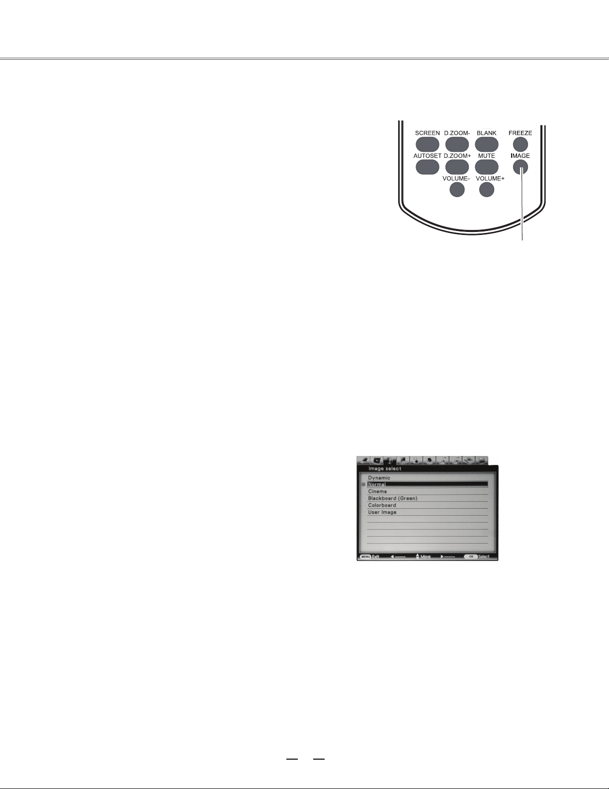
Image select
Image select
mode
Direct selection:
Use the key Image on the remote control to select the
image mode.
Operation through F. Menu
1. Press F. Menu to display the F. Menu. Press
▲
▼
to
select the icon
. Then press
or
press
Select.
2. Press ▲▼▼ to select the desired item, and then press
Select.
When the image is viewed in a room, select this mode.
This is the default image mode.
Multiple grey scales can be selected, and it s
uits for
watching movies.
This mode
can be used to project the image on a green
board to enhance the image quality. It mainly functions
on a green board, not black board.
This mode is suitable for projecting the image onto the
red, blue, yellow or green wallpaper.
This is the image mode pre-set by in the image
adjustment menu.
Remote control
Key for selecting an image mode
Menu for selecting image quality
Dynamic
Normal
Cinema
Blackboard(Green)
User Image
Colorboard
Page 34

33
Computer input
Image adjust
Image adjust
1. Press F. Menu on the remote control to display the on-screen
menu. Press to select the
icon
Then press
or press Select.
2. Press ▲▼▼ to select the item tOro be adjusted, and then press
press Select. At the time, the adjustment
dialogue box will appear. Press ◄►to set the value.
◄► to set the value.
Contrast
Press ◄ to decrease the contrast and press ► to increase it.
Brightness
Press ◄ to decrease the brightness and press ►to increase it.
Color temp.
Press◄► to select the desired color temperature (option
are “ H
igh”,
“ Mid ” and “low” )
Red
Press ◄ to make the red color lighter and press ►to make it stronger.
Green
Press ◄ to make the green color lighter and press ► to make it stronger.
Blue
Press ◄ to make the blue color lighter and press ► to make it stronger.
Sharpness
Press ◄ to soften the image and press ► to sharpen it.
Gamma
Press ◄► to adjust the grey level to achieve better contrast and balance.
Note:
● After white balance (red), white balance (green) or white
balance (blue) is adjusted, the color temperature will ch
ange to
“User”.
● When green board or color mixer is selected in the “
Image
select
”
, the c
olor temperature will change to “ blackboard”
or “ colorboard
”
Menu for adjusting image
▲
▼
Page 35

34
Computer input
Adjusting screen size
With E1655, the size of the screen can be re-set to the value
the user desires.
1. Press F. Menu on the remote control to display the
on-screen menu. Press to select the screen. Then
press or press Select.
2. Press ▲▼▼ to select the desired item, and then press
Select.
This function will make the width-height proportion of the
projected image consistent with the input signals.
This item provides the image with the original
size. If the
original image is larger than the screen (1024X768), E1655
will automatically enter the selection mode for image display
section. The user can press ▲▼◄►◄► to select the image
display section. During adjustment, the arrow turns red.
When the max. value is reached, the arrow will disappear.
This item provides normal video images with a width-height
proportion 16:9.
This item provides normal video images with a width-height
proportion 4:3.
Self-definition
This item can help users manually adjust the proportion and
position of the screen.
When thi
s item is select
ed, press ►. The indication of
self-definition will appear on the screen. You can press ▲▼
▲▼
to select the items to be adjusted.
Horizontal/vertical
:
To
adjust
the
horizontal/vertical proportion
of the screen.
H&V
:
When this item is enabled, the width-height proportion
will
be
locked.
The
vertical
proportion is displayed
in grey,
meaning “disabled”. You can
adjust
the
horizontal
proportion,
and
then
modify the
proportion of the screen on
the basis of
the w
id
th-height proportion.
Horizontal/vertical position: To adjust the horizontal/vertical
position of the screen.
Common : Use this item to save input adjusted
proportion.
When you press Select at this item, a dialog
box will pop
up for confirmation. To save the proportion, press Select
at Yes. If you select self-definition, the system will
use
the saved proportion.
Reset
:
This item allows you to re-set the adjusted
values.
In the initial sta
te, press Select, an
d a dialog box
wil
l
pop
up for confirmation. To re-set the parameters,
press Select
at Yes.
After you select the digital zoom +, the on-screen menu
will disappear, while the information on digital zoom +
appears. You can press Select to zoom in the image size
,
and press
▲▼◄► to move the image horizontally.
The moving is effective only when the image is larger
than the size of the screen.
You can also press D zoom or select
on the remote
control
to zoom in the projected image.
After you select the digital zoom -, the on-screen menu
will
disappear, while the information on digital zoom appears. You can press Select to zoom out the image
size. You can also press
on the
remote control to zoom out the projected image.
To exit the “digital zoom +/-“ mode, press and
all
other keys except Select.
To return to the original screen size, select “screen
size” in the menu “adjusting screen size” , or enter new
input source
in the menu “sel
ecting input source’
, or
use the keys▲▼ designed for
digital focus to adjust
the screen size.
√
Note:
●
E1655 can’tdisplay images
with
r
esolution
higher than 1920
×
1200. If the
r
esolution of
the
PC is high than this
value, you should adjust
it to
a lower value before E1655 is connected to the
PC.
●
●
Image data other than
XGA
(1024 x
768) will be
modified to those adaptable to the screen size in
the initial state.
If no signal is detected in the menu of
PC,
Authentic, 4:3 and digital focus +/- will be disabled.
Screen Menu
R
emote control
Normal
True
Digital zoom +
Digital zoom -
D.zoom - or select
Custom
Full
Wide
▲
▼
Keystone
This item is use to save the data when AC power
is interrupted, or the project image is re-set. You
can press
▲
▼
to switch over between the
items below:
Save: When the power line is disconnected, the
state of keystone correction can be retained.
Initial state: When the power line is disconnected,
the state of keystone correction is initialized.
You can also press ▲▼ to correct keystone
dis
tortion. At the time, the keystone correction
menu will appear on the screen.
D.ZOOM+/-
Navigation keys
Select
Page 36

35
AV Input
Selecting input source (video, S-video, Component, SCART, HDMI)
Direct selection
Press the input key on the control panel at the side of E1655 , or press Video, S-video, Component,
SCART, HDMI on the remote control, to select video, S-video and Component.
Operation through menu
1. Press F. Menu on the remote control to display the
F. Menu. Press to select the icon for
input source. Then press or p
ress Select.
2. Pre
ss ▲▼▼ to select “ video” or “ S
-video ”
, and then press Select.
Component
Select “Component” if the input source is a video
device connected to Y, Cb/Pb an
d Cr/Pr through the
component VGA cable.
Video
Select Video when input video signal is connected to
VIDEO terminal.
S-video
Select S-video when input video signal is
connected to the S-video.
SCART
Select “SCART” if the input source is a video device
connected to SCART IN/COMPUTER IN through the
SCART VGA cable.
HDMI
Connect to HDMI when the video signal is connected
to HDMI terminal.
Remote control
Video
Component
Input menu
S-VIDEO
▲
▼
Page 37

36
AV Input
Selecting AV system
1. Press F. Menu on the remote control to display
the on-screen menu. Press to select the
icon for input source. Then press or press
Select.
2. Press ▲▼▼ to select “ Component ”, “ video ”
or “ S
-video ” , and then press Select.
3. Press ▲▼ to select the system, and then
press
► or
press Select. Press ▲▼ to select the
signal format, then press Select.
Video or S-video
Auto
E1655 can automatically detect the input video
system and optimize its own state. If the video
system is PAL-M or PAL-N, you should manual
ly
select
the system.
PAL/SECAM/NTSC/NTSC4.43/PAL-M/PAL-N
If E1655 can’t reproduce the image, you should
select a specific signal format from PAL, SECAM,
NTSC, NTSC 4.43, PAL-M and PAL-N.
Component
Auto
E1655 can automatically detect the input video
system and optimize its own state.
Component video signal format
If E1655 can’t reproduce the image, you should
select a specific component video signal format
from 480i, 575i, 480p, 575p, 720p, 1035i and 1080i.
√ Note:
●
If SCART or HDMI is selected, AV system menu
will be disabled.
AV System Menu (Video or S-video)
AV System Menu (Component)
▲
▼
Page 38

37
Selecting image mode
Direct selection:
Use the key Image on the remote control to select
the image mode.
Menu selection
1. Press F. Menu to display the F. Menu. Press
to select the icon for image select . Then
press or press Select.
2. Press ▲▼
▼
to select the desired item, and then
press Select.
Dynamic
When the image is viewed in a room, select this
mode.
This is the default image mode.
Improved half-tone lifelike image mode.
Blackboard(Green)
This mode can be used to project the image on a
green board to enhance the image quality. It mainly
functions o
n a green boa
rd, not black board.
Colorboard
This mode is suitable for projecting the image onto
the red, blue, yellow or green wallpaper.
This is the image mode pre-set by in the image
adjustment menu.
Remote control
Key for selecting an image mode
Menu for Image select
AV Input
Normal
Cinema
User Image
▲
▼
Page 39

38
AV Input
Image adjust
1. Press F. Menu on the remote control to display the
on-screen menu. Press to select the icon for
image adjustment. Then press or press Select.
2. Press ▲▼▼ to select the item to be adjusted, and then
press Select. At the time,
the adjustment
dialogue box will appear.
Press ◄►
to set
press ◄► to set
the value.
the value or
Contrast
Press ◄ to decrease the contrast and press ►to increase
it.
Brightness
Press ◄ to decrease the brightness and press ►to
increase it.
Color
Press ◄ to decrease the color gamut and press ►to
increase it.
Tin
t
Press ◄► to select the appropriate tone for the image.
White balance (Red)
Press ◄ to make the red color lighter and press ►to
make it stronger.
White balance (Green)
Press ◄ to make the green color lighter and press ►to
make it stronger.
White balance (Blue)
Press ◄ to make the blue color lighter and press ►to
make it stronger.
Sharpness
Press ◄ to soften the image and press ► to sharpen it.
Gamma
Press ◄► to adjust the grey level to achieve better
contrast and balance.
Noise reduction
Enable this item to reduce the snow interference and
achieve more smoo
th and clear image.
Progressive
The interlaced video signal can be converted into images
in a progressive manner. You can select one from the
options below:
OFF: Disabled;
L1:
Projecting dynamic image;
L2: Projecting still image;
Film: This item is used for watching films. When
it is selected, E1655 will restore the images with hig
quality to reduce image distortion.
h
Menu for adjusting image
▲
▼
Page 40
39
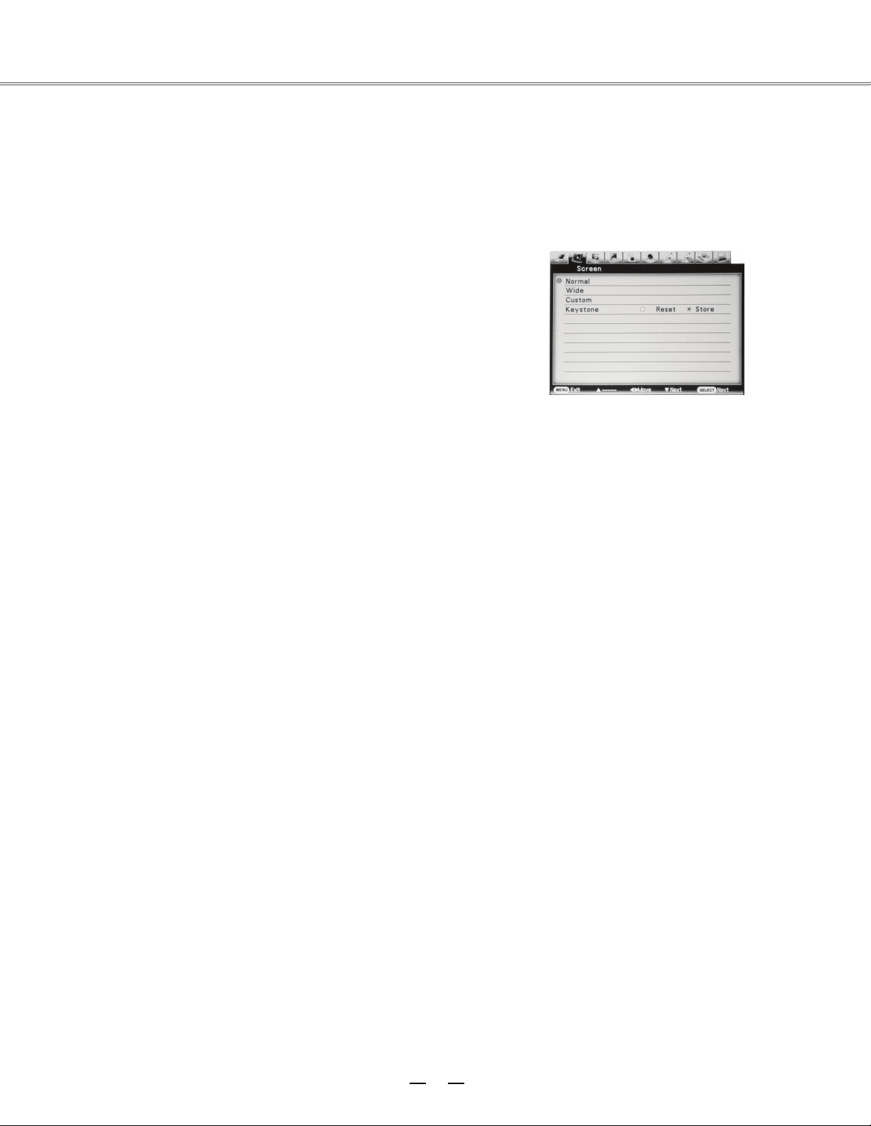
Adjusting screen size
With E1655, the size of the screen can be re-set to the value the
user desires.
1.Press F. Menu on the remote control to display the on-screen menu.
Press to select the screen. Then press or press Select.
2.Press ▲▼ to select the desired item, and then press Select.
Normal
This function will make the width-height proportion of the projected
image
consistent with the input signals.
Wide
This item provides normal video images with a width-height
proportion 16:9.
Custom
This item can help users manually adjust the proportion and
position of the screen.
When this item is selected, press ►. The indication of self-definition
will appear on the screen. You can press ▲▼ to select the items
to be adjusted.
Horizontal/Vertical:
To adjust the horizontal/vertical proportion
of the screen.
H&V: When this item is enabled, the
width-height proportion will be
locked. The vertical proportion is displayed in grey, meaning
“disabled”. You can adjust thehorizontal proportion, and then
modify the proportion of the screen on the basis of the width-height
proportion.
Honrizontal/Vertical Position:
To adjust the horizontal/vertical
position of the screen.
Common: Use this item to save input adjusted proportion. When you press Select
at this item, a dialog box will pop up for confirmation. To save the proportion, press
Select at Yes. If you select self-definition, the system will use the saved proportion.
Reset:
This item allows you to re-set the adjusted values. In the initial state,
press Select, and a dialog box will pop up for confirmation. To re-set the parameters,
press Select at Yes.
√Note:
●If no signal is detected, the system will be
automatically set as normal state. At the
time, the related dialog box disappears.
●The horizontal/vertical proportion and
of horizontal/vertical position should be
adjusted according to the input signal.
Screen Menu
AV Input
▲
▼
▼
Keystone
This item is use to save the data when AC power
is interrupted, or the project image is re-set.
You
can press
▲
▼
to switch over between the
items below.
Save: When the power line is disconnected, the
state of keystone correction can be
retained.
Initial state: When the power line is disconnected,
the state of keystone correction is initialized.
You can also press ▲▼ to correct keystone
dis
tortion. At the time, the keystone correction
menu will appear on the screen.
Page 41

40
menu
Setting
Setting
You can use E1655’s Setting menu to configure the
following functions.
1. Press F. Menu on the remote control to display the
on-screen menu. Press to select Setting.
Then press or press Select to enter the
submenu.
2.
Press
▲ ▼
▼
to select the desired item to be
adjusted, and then press
►
to switch the items.
▲
▲
►
▲
▼
Blue back
You can use this item to set the background of
E1655 for the time when no signal is detected.
You can press to switch over between the
items below:
ON: To enable the blue background for
projection;
OFF: To disable the blue background.
Display
You can use this item to set whether the startup animation is displayed.
ON: Show startup screen
OFF: Show the input image instead of the on-start screen
g
Terminal
The terminals, COMPUTER IN/MONITOR OUT, at the back of E1655 can be used for inputtin
data from a PC or outputting data to a monitor. You can press
▲
▼
to select Input
Input
or Output
:
Data input from PC
2.
Output : Data output to monitor.
On start
When this function is enabled, E1655
will be automatically
powered on so long as AC power source comes to the socket.
Rear
When this function is enabled, the images can be turned over leftward/rightwa
rd. You can project the
images to the screen behind E1655 .
Page 42

41
Setting
Standby mode
If you want to operate E1655 via the network, you can enable this function.
Normal: Even if E1655 is turned off, the network functions are still in active state. You can, through
the network, turn on or off the projector, change the network environment, and receive emails relating
to the projector at the time it is turned off.
Eco : Select this item when you don’t need to operate E1655 through the network. Once
selected, the network function is disabled when E1655 is turned off.
Cooling Fast
After E1655 is powered off, you can use the two options below to operate the cooling fan:
ON: Normal running.
OFF: The fan runs more slowly and produces less noise, but needs more time
High land
E1655 can allow user to control the fan through Setting menu.
You can select the running speed of the fan according to the altitude of the location where E1655 is
installed.
OFF: Normal speed. If the site where E1655 is used is of low altitude, you can set this item as OFF.
ON 1 : The fan runs faster than normal speed. When E1655 is operated in places with high altitude
(2000m), the cooling fan will produ
ce weaker
effects. So, you should select this item.
ON 2 : The fan runs faster than “ON 1 ”. When E1655 is operated in places with high altitude
(above 3000m), the cooling fan will produce weaker effects. So, you should select this item.
Ceiling
With this function, E1655can be inst alled to the ceiling to project images.
OFF: E1655 is in normal vertical position;
Auto : E1655 automatically identifi es its vertical or inverse state;
ON: E1655 is in inverse position.
Test pattern
This item allows you to set the internal signal of the system.
Lamp control
This item allows you to set the brightness of the
screen.
Normal :
The normal brightness.
Eco : Low brightness. It can reduce the power consumption and ensure the service life of the
lamp.
Auto
: Brightness is adjusted according to the input signal.
Page 43

42
Advanced setting
Advanced setting
Advanced setting
Advanced
Advanced setting
You can use E1655’s menu to configure
the following functions.
1. Press F. Menu on the remote control to display the
on
setting.
-screen menu. Press to select
Then press or press Select to enter
the submenu.
▼
▲
▼
2.
Press
▲ ▼
to select the desired item to be
adjusted, and then press
►
or press Select to
reach the selected item.
3.
Press
▲▼
▲▼
to select the desired item and then
press Select.
OSD language
OSD languages include English, Chinese, German,
French, Italian, Portugal, Dutch, Romanian, Spanish,
Polish, Finnish, Russian, Hungarian, Thai, Swedish,
Korean and Japanese.
►
Menu position
You can use this function t
Press select or to enter the menu
position. Then press to switch the items:
o change
the position
of on-screen menu.
Upper left,
U
pper right, Center, Lower left,
Lower right.
√ Note:
● The system can only detect the input source of
the last time.
● If you press PC, AV, S Terminal or Component
on-top control panel of E1655 or on its remote
control when input source search is under way,
the search process will s
top and the system will
return to the input signal used last time.
● In some PCs, the fine synch, total dots and
horizontal/vertical position can be adjusted
through the function “Auto PC adj”
If such
adjustment can’t bring about correct
image,
please adjust it manually.
Auto setup
If you press the automatic setup key on-top
control panel of E1655 or on its remote control,
the system will perform the functions of input
search and Auto PC adj.
You can switch over these functions by
following
the procedures below:
Input search
Wit
h this fun
ction, the system will automatically
detect the input signals. Once detected, the
search will stop. You can then press to
select one of the two items:
OFF: To disable the function;
ON: To enable the function. When the signal is
detected, the search will stop.
Auto pc adj
OFF:
To enable the function “Auto PC adj
”,
press the automatic setup
key on the
control
panel on E1655 or on its
remote control.
ON: To disable this function.
▲
▼
Page 44

43
Advanced setting
PIN code change
Press ▲▼ to select a number, press ►, and enter this number and move the cursor. At the time, the number will
change to the character “*”. If you entered a wrong number, you can press ◄ and move the cursor to the number to be
changed. Then press ▲▼ to select the correct number. Repeat the above process till a 3-digit number is entered.
A
fter you enter a 3-digit number, move the cursor to Enter. Then press Select, and you can start operating E1655.
If you entered a wrong startup-animation PIN code, the PIN code and the number (***) will turn red. Please enter the
correct startup-ani
mation
PIN code.
Re-setting logo PIN code
Enter a right 3-digit numbe, then press to switch over between off and on.
Changing logo PIN code
The PIN code for startup animation can be changed to a 3-digit number you desire. To do that, press Select, and
select the item of PIN code changing. At the time, the PIN
code dialog box will be popped up. You can press ▲▼ to
enter the correct PIN code. Then the dialog box for “new
startup animation PIN code” appears. You can enter a new
PIN code and select Yes. The new PIN code for start
up
animation is already set.
Do remember the new PIN code for the startup animation.
If you forget it, you can not re-set the PIN code.
Note:
After you change the PIN
code for startup animation, p
lease write down the new PIN code in the column “new
PIN code” in “memorandum for startup animation PIN code” on Page 59. Please keep this PIN code properly. If
you forget it or lose it, you can no longer change the PIN code.
Logo(“logo select” and “PIN code lock”)
You can use this item to set startup animation, logo and PIN code and to change the PIN code.
√ Note:
When logo select is on you can ’t select the startup animation and log.
Logo select
You can select from the following options as the startup animation:
User: To display the image you captured.
Default : To display the default startup animation.
OFF: No startup animation is di
splayed.
Capture
Th
is function is used to capture the projected image, which can be set as the startup image or image
interval.
Select Image Grabber and then press Select.
Make sure, when the dialog box appears, it is the captured image.
After the projected image is captured, you can use the function of selecting startup animation and set it
as User. After that, next time when E1655 is powered on, the captured image will appear on the
screen.
PIN code
You can use this item to prevent unauthorized people from changing your startup animation.
OFF: The startup animation can be modified through the “logo” menu.
ON: If one doesn’t know the PIN c
ode, he
can’t change the startup animation.
If you want to change the PIN code for startup animation, press Select. At the time, the dialog box
“logo PIN code” appears. You can change the PIN code by following the steps below.
▲
▼
Page 45

44
01 20
Power management
To preserve energy and retain the service life of the lamp, you can use this function to turn off the
lamp for the time when E1655 is not used.
Options are:
Ready: When the lamp is cooled, the power indicator turns green and flashes. When the system is
in this state, you can either to re-connect to signa ls or press any key on-top control panel of E1655 or
on the remote control to make the lamp illuminated again.
Shut down : When the lamp is cool enough, the power will be turned off.
Off : Function of Pow er managementr is disabled.
Timer: If no signal is input for o
ver 30 seconds and no key is pressed during that time, the characters
“no signal ” will appear on the timer. Then the system counts down the time till the lamp is turned off.
You can press ▲▼ to set the timer (1-30 minutes)
√ Note:
The factory default for standby time: 5 minutes.
Time left before the
lamp is turned off.
Power management
No signal
Advanced Setting
Page 46

45
Closed caption
This item allows the subtitle to be displa
yed for the audio contents or other information. If the input
source contains closed caption, you can enable this function and change the channel. Press to
select OFF, CC1, CC2, CC3 or CC4.
√ Note:
Only under the following circumstances can you select Closed Caption:
● The input signal source is of NTSC or S-video with compound video signal, and the system has
been set as Auto according to the signal.
● AV system of E1655 should be set as NTSC or Auto.
● When Closed Caption is disabled, it turns grey.
● When on-screen menu and Timer appear, Closed Caption can
’t be enabled.
Lamp control
This item allows you to set the brightness of the screen.
Normal :
The normal brightness.
Eco : Low brightness. It can reduce the power consumption and ensure the service life of the
lamp.
Auto : Brightness is adjusted according to the input signal.
Test pattern
This item allows you to set the internal signal of the system.
Security(“Key lock” and “PIN code lock”)
This item provides two options, “key lock” and “PIN code lock”, to ensure the security of the
projector’s operation.
Key lock
This function locks the on-top control panel of E1655 or the remote control to prevent the authorized
operation.
To en
able this function, select Key Lock and press Select, then press to select the desired item.
OFF: Unlocked.
Projector: Lock the on-top control panel of E1655. To unlock it, use the remote control.
Remote control: Lock the remote control. To un lock it, use the on-top control panel of E1655.
If the on-top control panel of E1655 is accidentally locked, and there is no remote control nearby or
the remote control malfunctions, you should contact the local distributor or the repair center.
▲
▼
Advanced Setting
▲
▼
Page 47

46
Advanced setting
PIN code lock
This function can prevent unauthorized operation of the projector. Optional items are:
OFF: Unlocked.
ON: You should enter the correct PIN code each time E1655 is powered on.
If you want to change the settings for PIN code locking or the PIN code (3-digit number), you should
enter the PIN code. The factory default PIN code is “111”’.
To the settings of PIN code locking, press Select and the system will pop up the PIN code box.
Entering PIN code
Press ▲▼ to select a number, press ►, and enter this number and move the cursor. At the time, the
number will change to th
e character “*”. If you entered a wrong number, you can press ◄ and move
the cursor to the number to be changed. Then press ▲▼ to select the correct number.
Repeat the above process till a 3-digit number is entered.
After you enter a 3-digit number, move the cursor to Enter. Then press Select, and you can start
operating E1655.
If you entered a wrong PIN code, the PIN code and the number (***) will turn red. Please enter the
correct startup-animation PIN code.
Re-setting PIN code for startup animation
Changing PIN code
The PIN code can be change
d to a 3-digit number you desire. To do that, press
Select,
and select the
item of PIN code changing. At the time, the PIN code dialog box will be popped up. You can press ▲
▼ to enter the correct PIN code. Then the dialog box for “new PIN code” appears. You can enter a
new PIN code.
Note:
After you change the PIN code, please write down the new PIN code in the column “new PIN code” in
“PIN code memorandum” on Page 59. Please keep this PIN code properly. If you forget is or lose it,
you can not open the projector.
Enter a right 3-digit numbe, then press to switch over between off and on.
▲
▼
Page 48

47
Advanced setting
Filter counter
This function is used to set a frequency for the filter cleaning.
When E1655 reaches specific time between cleanings, a Filter warning icon appears on the screen,
suggesting it is time for cleaning. After cleaning the filter, make sure you have selected Reset and set
the timer. The filter warning icon will not disappear until the filter timer is reset.
Warning log
This fun
ction allows E1655 to record abnormal
operations, according to which errors can be
diagnosed. The log list will display 9 warning
messages, which are sorted according to the time.
√ Note:
When Factory Default is selected, all log
records will be
deleted.
Factory default
You can use this function to reset all values to
factory default, except for startup animation, PIN
code lock, startup animation PIN code lock, lamp
timer and filter timer.
Page 49

48
。
Information
Displaying input source
The information menu is used to detect signal of projected image and running state of E1655.
Operation through menu
Press to select the information. And the information menu will appear.
You can then see the information displayed as follows:
It displays the selected input source and the current signal format.
The h-sync frequency of input signal appears in KHz. When no signal is avai lable, it displays KHz.
The v-sync frequency of input signal appears in KHz. When no signal is available, it displays Hz.
When progressive displaying is activated, frequency (in Hz) will be multi
plied.
Screen
It displays the selected screen mode.
It displays what OSD language is used.
It displays the selected lamp mode.
It displays the power control mode.
Key lock
It displays OFF, Remote Control or Projector.
Input
H-sync freq.
V-sync freq.
Language
Lamp status
Power management
▲
▼
Page 50

49
。
“Warning Temper” indicator
The “Warning Temper” indicator tells in what protection state E1655 is engaged. The user should
check the “Warning Temper” indicator and power indicator to make sure they work.
Projector is in OFF state, and “Warning Temper” indicator flashes red.
When its internal temperature exceeds the normal value,
E1655 will be automatically powered off to protect
the parts. When E1655 is in a cooled state, the power
indicator will blink. When it is cooled enough (restore
the normal operating temperature), you can press the
powe
r key to start up the system.
√ Note:
When E1655 restores its normal operating temperature,
the “Warning Temper” indicator will flash continuously.
If you re-start the projector, it will stop
flashing.
Check the items below:
-Whether the site where E1655 is installed is well
ventilated, and whether t he vent is blocked.
-Whether E1655 is installed near the vent of air
conditioner. Note it can not be installed at that place.
-Whether the filter is clean. You should clean it
regularly.
Projector is in OFF sta
te, and “Warning Temper ”
in
dicator is illuminated red.
When any abnormity in E1655 is detected, E1655
will be automatically powered off to protect its internal
parts. At the time, the “Warning Temper” indicator will
be illuminated red. In this case, you should unplug the
power cord and plug it again, then power on the
projector
again for check. If the projector is still in OFF
state and
“Warning Temper” indicator is illuminated red,
you should
unplug the power cord and contact the
repair center for
maintenance.
On-top control panel
“Warning Temper” indi
cator is illuminated red.
Note:
When abno
rmity occurs, the user should cut
off the AC power. Otherwise, it may lead to
fire or electric shock.
On-top control panel
“Warning Temper” indicator is illuminated red.
Maintenance
Page 51

50
Note:
Keep E1655 from dust and smog.
Otherwise, the image quality may deteriorate.
When E1655 is operated in an environment
with dust and smog, the dust and dirt will
accumulate on its lens, liquid crystal board or
the lens assembly inside the projector. If that
happens, you should contact the local
distributor or repair center for correct
cleaning.
Maintenance
Cleaning the filter
The filter prevents dust from accumulating on the surface of lens assembly in E1655, Should the
filter become clogged with dust particles, it will reduce the cooling fan’s effectiveness and may result
in in
ternal heat buildup and adversely affect the life of the projector. If a Filer warning icon appears on
the screen, you should clean the filter immediately. To do that, follow the steps below:
1. Turn off the projector, and unplug the AC power
cord from the outlet.
2. Remove the air filter from the projector.
3. Brush the filter clean.
4. Install the filter onto the projector again and make
sure it is secured properly.
Note:
Do not operate the projector when the
filter is removed. Otherwise, dust
will be
accu
mulated on lens and thus affect the
image quality.
Never attempt to place any objects to the
air intake vents. Otherwise, the projector
may malfunction.
Filter
Resetting the filter counter
1. Press F. Menu on the remote control to display the
F. Menu. Press to select the icon for the
menu. Then press or
Select.
2. Press ▲▼▼ to select Filter counter
, and then press
► or
press Select. Press ▲▼ to select Filter counter
reset ,
then press Select. At the time, you will see
the prompt information “Filter counter ? ” displayed
on the screen. Select Yes.
3. When another
dialog box pops up, you should
selec
t Yes and reset the filter.
▲
▼
advanced setting
reset
Page 52
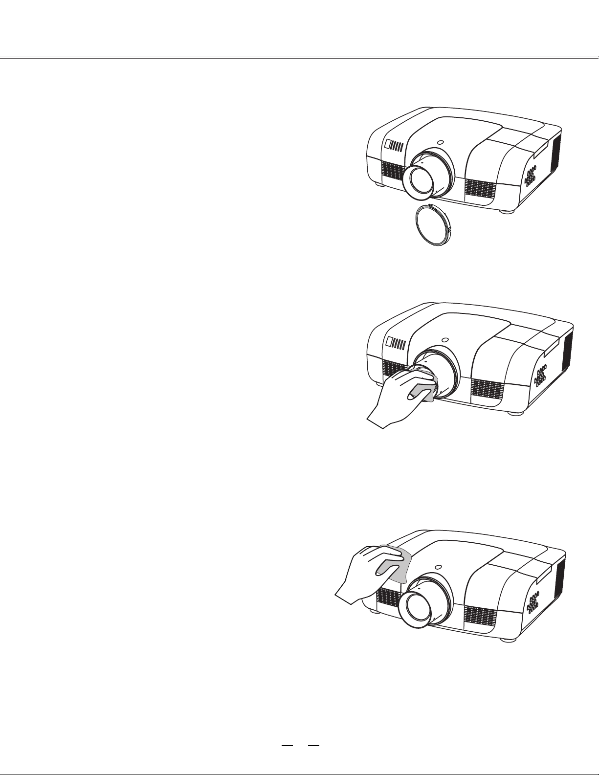
Covering the lens properly
If E1655 needs to be moved or won’t be used for
extended period of time, you should cover the lens
properly.
Cleaning the lens
Unplug the AC power cord before cleaning.
Apply some non-abrasive cleaning agent exclusively
designed for cameras onto a piece of clean cloth, and then
use it to wipe the lens ge ntly. Or you can use cleaning
paper or commercial blower to clean the lens.
Maintenance
Avoid excessive use of cleaning agent. Abrasive cleaning
agent, solvent or other coarse chemicals may scratch the
lens.
Clean
Unplug the AC power cord before cleaning.
Use a piece of clean cloth to gently wipe the surface of
projector. If the projector is quite polluted, you can apply
some neutral cleaning agent onto a piece of clean cloth,
and use it to wipe the shell. Avoid excessive use of
cleaning agent. Abrasive cleaning agent, solvent or other
coarse chemicals may scratch the lens.
When E1655 is not used, you should put it into a bag to
avoid dust and scratch.
he projector’s shell
ing t
51
Page 53

52
To replace the lamp, follow the steps below:
1. Power off the projector and unplug the power
cord. Then let the project cool for at least 45
minutes.
2. Loosen the screws on the lamp cover and open
the cover.
3. Make sure the lamp is well protected and
remove two screws. Hold the handle and pull
out the lamp.
4. Install a new lamp with the same model and
tighten the two screws. Make sure the
installation is correct. Put lamp cover in place
and then tighten the screws.
5. Plug the AC power cord and power on the
projector.
Screw
Handle
Lamp
Screw
Screw
Lamp
cover
Note:
When the lamp isn’t illuminated, it may indicate that the lamp has been damaged.
When you replace the lamp in a projector installed on the ceiling, you should stand beside the lamp
cover but not under it; for the broken glass may fall down to hurt you. To do that, remove the lamp
cover gently to avoid being hurt by the dropped glas s. If glass drops into your eyes or mouth, you
should see the doctor immediately.
Note:
Note:
As temperature inside the projector is high, you
should cool the projector for at least 45 minutes
before you open the lamp cover.
For the sake of safety, only use the lamp of the
same model. Never drop the lamp onto the ground
nor touch the glass bulb! The glass can shatter and
hurt.
Maintenance
Replacing the lamp
When the service life of the projection lamp is over, the
icon suggests that the lamp needed to be replaced will
appear on the screen, and the indicator for the
replacement will flash yellow. If so, you should
immediately replace it with a new one of the same model.
The flashing time of the replacement indicator is subject
to the lamp mode.
Page 54

53
●
:E1655
●
:APU-L8
Maintenance
Changing the lamp model
Purchasing new lamps
Users can buy new lamps through the local distributor. Your purchase order should include the
information below:
Projector model
Lamp model
This projector uses a high-pressure lamp which must be handled carefully and properly.
Improper handling may result in accidents, injury, or create a fire hazard.
● Lamp life may differ from lamp to lamp and according to the environment of use. There is no guarantee
of the same life for each lamp. Some lamps may fail or terminate their life in a shorter period of time
than other similar lamps.
● If the projector indicates that the lamp should be replaced, i.e., if the LAMP REPLACE indicator lights
up, replace the lamp with a new one IMMEDIATELY after the projector has cooled down.
(Follow carefully the instructions in the Lamp Replacement section of this manual.) Continuous use of
the lamp with the LAMP REPLACE indicator lighted may increase the risk of lamp explosion.
● A Lamp may explode as a result of vibration, shock or degradation as a result of hours of use as its
lifetime draws to an end. Risk of explosion may differ according to the environment or conditions in
which the projector and lamp are being used.
IF A LAMP EXPLODES, THE FOLLOWING SAFETY PRECAUTIONS SHOULD BE TAKEN .
If a lamp explodes, disconnect the projector’s AC plug from the AC outlet immediately. Contact an
authorized service station for a checkup of the unit and replacement of the lamp. Additionally, check
carefully to ensure that there are no broken shards or pieces of glass around the projector or coming out
from the cooling air circulation holes. Any broken shards found should be cleaned up carefully. No one
should check the inside of the projector except those who are authorized trained technicians and who
are familiar with projector service. Inappropriate attempts to service the unit by anyone, especially those
who are not appropriately trained to do so, may result in an accident or injury caused by pieces of broken
glass.
LAMP HANDLING PRECAUTIONS
Page 55

54
Appendix
Troubleshooting
Before you contact the local distributor or repair center, you may check the items below once again.
-Make sure you have properly connected E1655 to the peripheral equipment.
-Make sure all equipment has been connected to AC power source and the power source is in ON state.
-If E1655 can’t project image output from a PC, please re-start the PC.
noituloS
eruliaF
Machine can’t be powered on -Plug the power cord of the projector into the AC power outlet.
-Check whether the power indicator
turns red.
-Only when the power indicator turns red can you power on the
projector again.
-Check the Warning Temp indicator. If it is illuminated red, you can’t
power on E1655.
-Check the projection lamp.
-Unlock the “key lock” function.
No initial displaying -Make sure both displa ying and count-down functions are enabled.
Initial displaying is inconsistent
with
factory defaults
-Make sure the item User or OFF is not selected in the startup
animation.
Input signals are automatica
lly switched
(can’t
be switched)
-Adjust the search function of input source properly.
When input is pressed during startup, a
non-Lamp icon appears.
-This icon warns that the filter needs to be replaced.
An icon of non-input mode or lamp mode
appears
-This icon indicates the replacement of lamp or warns for the filter.
Ambiguous images -Adjust the focus of E1655
-Set a more proper projection distance.
-Check whether the lens needs to be cleaned.
-When E1655 is moved from a environment with low temperature
to
the one with higher temperature, water will be condensed on the lens. If
so, you have to wait till the condensed water disappears.
Image turns over leftward/rightward
Image turns over upward/downward
-Check the function of “ceiling/rear”
.
-Ch
eck the function of “ceiling”
.
Image not bright enough
-Check whether the contrast or brightness is adjusted correctly.
-Check whether the image mode is properly selected.
-Check the function of lamp brightness adjusting.
-Check the lamp and replace the indicator. If the
indicator is illuminated,
it means the service life of the lamp is over. You should replace the lamp
with a new one of the same model immediately.
Page 56

55
Appendix
No image -Check the connection between PC or video equipment and E1655 .
-Check with the signal from PC is correct. If E1655 is connected to
certain laptops, the settings of their video adapters need to be changed.
You can refer to the operating instructions of the PC for such
modification.
-Images can show up only about 20 seconds after the projector is
powered on.
-Check the input signal, color system, video system or PC system mode.
-Make sure that the temperature doesn’t exceed the permi
tted operating
temperature (41F–95
F [5
C–35
C]).
-If
non-displaying function is enabled, no image will appear on the
screen. You can then press the non-display key or other keys.
No sound is heard. -Check that the audio cable from the input source is correctly connected.
-Adjust the audio source.
-Press the key “+”.
-Press the key “Mute”.
-If the audio cable is inserted into the port AUDIO OUT, the internal
speaker of the projector will be disconnected.
-Is there any
image project
ed? Only when the image appears on the
screen, can the sound be heard.
Abnormal color -Check the input signal, color system, video system or PC system mode.
-Make sure the
blackboard(green)
is not selected in the item “Image select”
Some information can’t be seen in the
operation.
-Check the function of displaying.
Automatic adjustment through PC can’t
be effective.
-Check the signal of input source. Automatic adjustment through PC
won’t be effective when 480p, 575p, 720p,
480i, 575i, 1035i or 1080i is
selected.
Settings can’t be saved after the system is
powered off.
-Make sure you have selected “store” after you changed the settings.
Some settings can’t be saved if “store” is not selected.
Ineffective power control
-When the system is standstill, or no-display function is enabled, the
power control is ineffective.
Ineffective icon selection
-Check the wiring and the signal of input source, and make sure there is
signal.
Ineffective automatic setting
-Make sure all functions in automatic setting are
enabled.
-Make sure the function of ceiling is not enabled.
Page 57

56
Appendix
Distorted image or no image
-Check and adjust the PC menu or on-screen menu.
The PIN code dialog box popes up in the
startup
process
-A PIN code is set for locking.
Remote control doesn’t work
-Check the battery.
-Make sure there is no obstacle
between the projector and the
remote control.
-To use the remote control, keep it within 5 meters away from the
projector.
-Make sure the code of the remote
control is consistent with the
projector.
-Unlock the key through the setup menu.
The indica
tor is illuminated or flashes
-Check the state of the projector according to the indicator.
Excalmatory point appears on the screen -Ineffective
operation. You should operate the system correctly.
The side control panel doesn’t work
-Unlock the keys on the side control panel through the item
“security” in the setup menu.
PIN code lock for startup animation, key lock
and PIN code lock can’t be unlocked.
-Contact the local distributor or the repair center.
Warning:
E1655 is operated with high voltage. Do not open its casing!
If the problem still exists after you take the aforesaid measures, you should contact the local distributor or the repair
center and tell the machine model. w
ASK Poxima
ill tell you how to handle the issue.
Page 58

57
POWER
WARNING
LAMP
SHIFT
FOCUS
?
?
green
red
yellow
off
green flash
green flash
*When the projector bulb reaches its endurance, the indicator light will be yellow and you need to
change the bulb.
Appendix
Indicator and projector state
Check the indicator to know about the state of projector.
Indicator
(Green/red) (Red) (Yellow) (Blue)
(Green)
State of projector
E1655 is in power-off state (AC power cord not
inserted).
E1655 is in standby state. Press ON/STNADBY to
power on the projector.
E1655 is in normal working state.
E1655 is ready to be in standby mode or the
projection lamp is being cooled. Bef
ore
you power
on the projector, you should wait till the lamp is cool
enough and the power indicator flashes.
E1655 is in suspension state.
Internal temperature too high. E1655 can’t be
powered on. When the projector is cool enough, the
temperature is restored to the normal value and the
power indicator is illuminated red, you can then
power on the projector (The indicator Warning Temp
keeps on flashing).
When the projector is cool enough, the temperature
is restored to the normal value and the power
indica
tor is illuminated red, you can then power on
the projector, At the time, the indicator Warning
Temp stops flashing.
E1655 can’t be powered on because error is
detected. You should unplug the power cord. Then
insert it again and power on the projector. If the
projector is powered off again, you should cut off
the power and contact the local distributor or repair
center. In this case, stop the projector. Otherwise,
electric shock or fire may occur.
The service li
fe
of the lamp is over. You should
replace it with a new one in time.
Lens is moving and being adjusted.
Focus being adjusted.
blue
Page 59

58
640x400 60
1152x900 65
640x400 70
1152x900 75
640x400 85
1280x1024 60
640x480 60
1280x1024 65
640x480 65
1280x1024 70
640x480 72
1280x1024 72
640x480 75
1280x1024 75
640x480 85
1280x1024 85
800x600 50
WXGA 1280x768 60
800x600 60
1280x768 75
800x600 65
1280x768 85
800x600 72
1280x768 120
800x600 75
1360x768 60
800x600 85
1360x768 72
800x600 120
1366x768 60
832x624 75
1280x800 60
XGA 1024x768 60
1280x800 75
1024x768 65
1280x800 85
1024x768 70
1280x800 120
1024x768 72
1080psf24
1
920x1080 2
4
1024x768 75
1080psf25
1920x1080 25
1024x768 80
1080psf30
1920x1080 30
1024x768 85
480i 60
1024x768 120
575i 50
1152x864 70
480p 60
1035i 60
575p 50
1080i 60
720p 50
1080i 50
720p 60
SXGA
VGA
SVGA
Appendix
Compatible PCs
E1655 is compatible with all analog and digital signal formats under 160MHz of DCLK, whose resolution and
correspondent field frequencies are listed below:
Note:
The specification is subject to change without prior notice.
Signal format Resolution Field frequency(HZ)
Signal format Resolution Field frequency(HZ)
When E1655 is controlled via PC, you should use SI control cable (bus-to-bus crossover) to connect the PC to
the control terminals of E1655.
Page 60

59
5
1
2
34
10
9 678
15
14
13
1112
-----
1
5
2
4
3
6
7
8
-----9
13
10
12
11
14
15
RX –
TX +
TX –
RX +
2
3
4
8 7 6 5 4 3 2 1
5
6
7
8
1 -----
-----
----------
-----
R X D
T X D
-----
GND
-----
1
2
3
4
5
6
7
8
-----9
-----
-----
PIN code memorandum
Write down the PIN code in the blank below and keep it with
E1655, please contact the repair center.
PIN code lock
*If this 3-digit number is changed,
the factory
default number will be ineffective.
Factory default PIN code 111*
Factory default PIN code 111*
Locking startup-animation PIN code
Appendix
Configuration of terminals
OMPUTER IN 1/COMPUTER IN 2/MONITOR OUT (analog)
Terminal: Analog RGB (D-sub 15-pin)
CONTROL PORT terminal (D-SUB-9-Pin) LAN terminal
Red (Input/output)
Green (Input/output)
Grounding (field synchronizing)
Blue (Input/output)
Grounding
DDC data
Grounding (line synchronizing)
Horizontal synchronizing
(compound sync.) input/output
Grounding (red)
Vertical synchronizing
input/output
Grounding (green)
DDC clock
Grounding (blue)
Page 61

61
3 0 0
1 5 0
2 3 8
5 8
1 0
534.5
193.4
176.9
146
380 5.
398 5.
465 1.
LCD PROJECTOR
LENS RELEASE
LCD PROJECTOR
114
Appendix
Outer dimensions
Content of hazardous substances and elements in E1655
Name of parts
Hazardous substances and elements
Plastic parts
Pb Hg Cd Cr6+ PBB PBDE
Metal parts
○ ○ ○ ○ ○
Optical parts
○
○
○ ○ ○ ○ ○
PCB assembly
× ○ ○ ○ ○ ○
Body
Other parts
× ○ ○ ○ ○ ○
Remote control
× ○ ○ ○ ○ ○
Accessories
Cable
× ○ ○ ○ ○ ○
○: It means that contents of hazardous substances in all homogeneous materials in this part don’t
exceed “Required Limitations” specified in SJ/T11363-2006.
×: It means that contents of hazardous substances in at least one homogeneous material in this part
exceed “Required Limitations” specified in SJ/T11363-2006.
Unit: mm
Screw hole used when E1655 is
installed on the ceiling
Screw:MB
Depth:10.0
Page 62

62
1.8-2.3
1.7-2.2
1.8-2.3
1.8-2.3
13.05
Flred/Power
NO
YES
YES
YES
YES
2.0
73.9-117.1
45.6-73.8
22-35
20.4-27.6
X1.3/Power
X1.6/Power
X1.6/Power
X1.6/Power
Appendix
Optional parts
Wide-range
lens
tandard lens
Ultra-long
-focus
lens
Appearance
Electric
Zoom/Focus
Foci(mm)
F value
Replacing lens
E1655’s lens can be replaced by those of other models, a design that allows the projector to be used for
multi-purposes.
If you want to install or replace the lens, you should contact the local distributor. Only qualified sales personnel or
repair engineers are permitted to install or replace the lens. To avoid injury, never attempt to install or replace the
lens without permi
ssion.
When you need to lift or move E1655, do not grasp the lens for that purpose. Otherwise, the projector
may be seriously damaged.
To sales personnel and repair engineers:
For information on installation and replacement of lens, please refer to related operating instructions. Before
installing or replacing the lens, make sure the model of the lens is correct to E1655.
Short-focus
lens
lens
Telephoto
Type
Listed below are optional parts. Users should provide distributors with such information as part name and model
when
they place the order.
Page 63

 Loading...