


www.proxicast.com
LAN-Cell 2
3G Cellular Router + VPN + Firewall
User’s Guide
Version 4.02
November 2008
Edition 2


Contents Overview
Contents Overview
Introduction ............................................................................................................................25
Getting to Know Your LAN-Cell 2 .............................................................................................. 27
Introducing the Web Configurator & Home Screen ...................................... ... ... .... ... ... ... ... .... ... 35
Tutorials: 3G Modem Setup & VPN Wizard ............................................................................... 53
Network & Wireless Menus ...................................................................................................75
LAN Screens .............................................................................................................................77
WAN & 3G Cellular Screens ............... ... ............................................................. .... ... ... .............89
DMZ Screens ........................................................................................................................... 127
Wireless LAN (WLAN) Screens ...............................................................................................137
Wi-Fi Screens ........... ... ... .... ... .......................................................... ... ... .... ... ... ... .... ... ... ........... 163
Security Menu ......................................................................................................................179
Firewall Screens ...................................................................................................................... 181
IPSec VPN Config Screens ..................................................................................................... 209
Certificates Screens ................................................................................................................255
Authentication Server Screens ........... ... ... ... .... ... ... ... .... ... ... ..................................................... 283
Advanced Menu ...................................................................................................................287
Network Address Translation (NAT) Screens .......................................................................... 289
DNS Screens ............................................ ... .... ... ... ... .... ... ... ... .................................................. 307
Remote Management Screens ................................................................................................319
Static Route Screens ...............................................................................................................339
Policy Route Screens ..............................................................................................................343
Bandwidth Management Screens .................... ... .....................................................................349
ALG Screens ........................................................................................................................... 365
Custom Application Screens ...................................................................................................371
Logs and Maintenance Menus ............................................................................................373
Logs Screens ........................................................................................................................... 375
Maintenance Screens ..............................................................................................................397
System Management Terminal ...........................................................................................411
Introducing the SMT ................................................................................................................413
General Setup .......... .......................................................... ... .... ... ... ... ... .... ... ... ... .....................421
WAN, 3G and Dial Backup Setup .......................................... .... ... ... ... ... .... ... ... ........................ 427
LAN Setup ............................................................................................................................... 441
LAN-Cell 2 User’s Guide
3

Contents Overview
Ethernet WAN Internet Access ................................................................................................447
DMZ Setup .............................................................................................................................. 453
Route Setup .............. ... ... .... .......................................................... ... ... ... .... ... ...........................457
WLAN Setup ............................................................................................................................461
WAN ISP Setup ........... ... .... ... ... ... .... .......................................................... ... ... ... .... ... ... ... ........ 465
IP Static Route Setup ..............................................................................................................473
Network Address Translation (NAT) ........................................................................................ 477
Firewall Status ......................................................................................................................... 497
Filter Configuration ..................................................................................................................499
SNMP Configuration ................................................................................................................515
System Information & Diagnosis .............................................................................................517
Firmware and Configuration File Maintenance ........................................................................ 529
System Maint. Menus 8 to 10 .................................................................................................. 543
Remote Management ..............................................................................................................551
IP Policy Routing ......................................... ........................................................... ... ... ...........555
Call Scheduling ........................................................................................................................ 563
Troubleshooting and Specifications ..................................................................................567
Troubleshooting ..................................................... .................................................................. 569
Product Specifications ............................................................................................................. 575
Appendices ...........................................................................................................................581
4
LAN-Cell 2 User’s Guide

Table of Contents
Table of Contents
Contents Overview ...................................................................................................................3
Table of Contents......................................................................................................................5
About This User's Guide........................................................................................................19
Document Conventions..........................................................................................................20
Safety Warnings ......................................................................................................................22
Part I: Introduction................................................................................. 25
Chapter 1
Getting to Know Your LAN-Cell 2..........................................................................................27
1.1 LAN-Cell 2: 3G Cellular Router + VPN + Firewall Overview ............................................... 27
1.2 Ways to Manage the LAN-Cell ..................................................................................... .... ... 27
1.3 Good Habits for Managing the LAN-Cell ............................................................................. 28
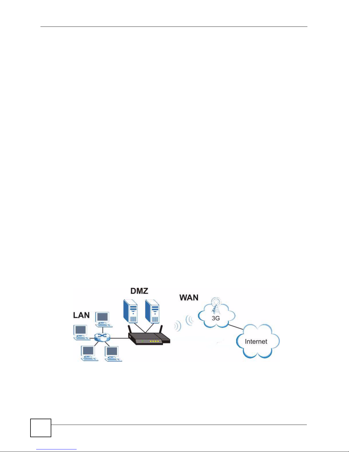
1.4 Applications for the LAN-Cell ........................ ....................... ................... ...................... ....... 28
1.4.1 3G WAN Applications ................................................................................................. 28
1.4.2 Redundant Secure Broadband Internet Access via Ethernet or Cellular ................... 29
1.4.3 VPN Application ............................................ ... ... ... .... ... ... ... ....................................... 29
1.5 Front Panel Indicators ........ ... .... ............................................................. ... ... .......................30
1.6 Rear Panel Connections ...................................................................................................... 31
1.7 Card-Lock ........ ... ... .......................................................... .... ... ... ... ... .... ................................ 32
Chapter 2
Introducing the Web Configurator & Home Screen.............................................................35
2.1 Web Configurator Overview .................................................................................................35
2.2 Accessing the LAN-Cell Web Configurator ..........................................................................35
2.3 Navigating the LAN-Cell Web Configurator ......................................................................... 37
2.3.1 Title Bar ...................................................................................................... ... ... .......... 37
2.3.2 Navigation Panel ....................... ... .... ..........................................................................38
2.3.3 Main Window .......................... ... .......................................................... .... ... ... ... ... .... ...40
2.3.4 HOME Screen .................... ... ... ... .... .......................................................... ... ... ... .... ... 41
2.3.5 Port Statistics ...........................................................................................................45
2.3.6 Show Statistics: Line Chart .................................... .... ... ... ... ....................................... 46
2.3.7 DHCP Table Screen ................................................................................................ 47
2.3.8 VPN Status ................... .... ... ... ... ... .... .......................................................... ... ... ... ....... 48
LAN-Cell 2 User’s Guide
5

Table of Contents
2.3.9 Bandwidth Monitor .................................................................................................... 49
2.3.10 Status Bar .................................................................................................................50
2.4 Resetting the LAN-Cell .... .................................................................................................... 51
Chapter 3
Tutorials: 3G Modem Setup & VPN Wizard...........................................................................53
3.1 Setting Up a 3G WAN Connection ....................................... ... ... ... ... .... ... ... .......................... 53
3.1.1 Inserting a 3G PC-Card ........................................................................... ... ... ... ... .... ... 53
3.1.2 Configuring 3G WAN Settings ................... .... ... ... ... .................................................... 54
3.1.3 Checking WAN Connections ...................................................................................... 55
3.2 VPN Wizard Overview ........................................................................................................ 57
3.2.1 VPN Wizard Gateway Setting ....................................................................................57
3.2.2 VPN Wizard Network Setting ..................................................................................... 58
3.2.3 VPN Wizard IKE Tunnel Setting (IKE Phase 1) ......................................................... 59
3.2.4 VPN Wizard IPSec Setting (IKE Phase 2) ................................................................. 61
3.2.5 VPN Wizard Status Summary .................................................................................... 62
3.2.6 VPN Wizard Setup Complete ........... .......................................... ................................ 64
3.3 Security Settings for VPN Traffic ......................................................... ... ... ... .... ... ... ... ... .... ... 66
3.3.1 Firewall Rule for VPN Example .................................................................................. 66
3.3.2 Configuring the VPN Rule ..........................................................................................66
3.3.3 Configuring the Firewall Rules ................................................................................... 70
Part II: Network & Wireless Menus....................................................... 75
Chapter 4
LAN Screens............................................................................................................................77
4.1 LAN, WAN and the LAN-Cell ...............................................................................................77
4.1.1 What Yo u Can Do in The LAN Screens .....................................................................77
4.1.2 What You Need to Know About LAN ...... ... .... ... ... ... .... ................................................ 78
4.2 LAN Screen ..................................... ... ... .... ... ... ... ................................................................. 80
4.3 LAN Static DHCP Screen ...... .... ... ... ... ... .... .......................................................... ... ... ... .... ... 83
4.4 LAN IP Alias Screen ........................................................................................................... 84
4.5 LAN Port Roles Screen .......................................................................................................86
Chapter 5
WAN & 3G Cellular Screens...................................................................................................89
5.1 Overview ............. .......................................................... ... .... ... ... ... ....................................... 89
5.1.1 What Yo u Can Do in the WAN Screens ..................................................................... 90
5.1.2 What You Need To Know About WAN ........................................ ... ... ... .... ... ... ... ... .... ... 91
5.2 WAN General Screen .......................................................................................................... 94
5.2.1 Configuring Load Balancing ................ ... ... .... ............................................................. 97
6
LAN-Cell 2 User’s Guide

Table of Contents
5.2.2 WAN Connectivity Check ......................................................................................... 101
5.3 WAN Screen ........................................................................................... ... ... .... .................103
5.3.1 WAN Ethernet Encapsulation ................................................................................... 104
5.3.2 PPPoE Encapsulation ..............................................................................................107
5.3.3 PPTP Encapsulation .............................................. .... ... ... ... ... .... ...............................110
5.4 Cellular (3G WAN) Screen .................................................................................................114
5.4.1 Configuring 3G Network Access Parameters ......... .... ... ... ... ... .... ... ............................115
5.4.2 Configuring Cell-Sentry Budget Control ....................................................................118
5.5 Traffic Redirect Screen ...................................... .... ... ... ... .................................................. 120
5.5.1 Configuring Traffic Redirect .............................................. ... ... .................................. 120
5.6 Dial Backup Screen ............ ... .... ... ... ... ...............................................................................122
5.6.1 Advanced Modem Setup ........................................................................................ 124
5.6.2 Configuring Advanced Modem Setup .............. ... ... .... ... ... ... ... .... ... ... ... .... ... ..............125
Chapter 6
DMZ Screens.........................................................................................................................127
6.1 Overview .......................................................................................................................... 127
6.1.1 What You Can Do in the DMZ Screens ....................................................................127
6.1.2 What You Need To Know About DMZ ....... .... ... ... ... .... ... ... ... ... .... .............................. 127
6.1.3 DMZ Public IP Address Example .............................................................................128
6.1.4 DMZ Private and Public IP Address Example ..........................................................129
6.2 DMZ Screen ....... ... ... .... ... ... ... .... ... .....................................................................................129
6.3 DMZ Static DHCP Screen .................................... ... ... ... .... ... ... ........................................ 132
6.4 DMZ IP Alias Screen ......................................... ............................................................... 133
6.5 DMZ Port Roles ............. ... ... .... .......................................................... ... ... ... .... ... ... ...........135
Chapter 7
Wireless LAN (WLAN) Screens............................................................................................137
7.1 Overview ............. .......................................................... ... .... ... ... ... ..................................... 137
7.1.1 What You Can Do in the WLAN Screens ................................................................. 138
7.1.2 What You Need to Know About Wireless LAN ........................... ... ... ... .... ... ... ... ... .... . 1 38
7.2 WLAN Screen .................................................................................................................. 139
7.3 WLAN Static DHCP Screen .............................................................................................. 141
7.4 WLAN IP Alias Screen .......................................................................................................142
7.5 WLAN Port Roles Screen ................................................................................................. 144
7.6 Wireless Security Overview ............................. ... .... ... ........................................................ 147
7.6.1 SSID ................................................. ... ... .......................................................... ........ 147
7.6.2 MAC Address Filter ...................... ....................................................................... ..... 147
7.6.3 User Authentication .......................................... ... ... .... ... ... ........................................ 147
7.6.4 Encryption .............................................. .......................................................... ... ..... 148
7.6.5 Additional Installation Requirements for Using 802.1x ............................................. 149
7.7 Internal Wi-Fi Access Point Setup .................................................................................... 150
7.7.1 SSID Profile ........................... ... ... ........................................................... ... ... ... ... ..... 152
LAN-Cell 2 User’s Guide
7

Table of Contents
7.8 Configuring Wireless Security ........................................................................................... 153
7.8.1 No Security .......................... ... .......................................................... ... .... ... ... ... ........155
7.8.2 Static WEP ............. ... ... .... ... .......................................................... ... ... .....................155
7.8.3 IEEE 802.1x Only .....................................................................................................156
7.8.4 IEEE 802.1x + Static WEP ....................................................................................... 157
7.8.5 WPA, WPA2, WPA2-MIX ........ ... ... .... ... ... .......................................................... ... .... . 1 59
7.8.6 WPA-PSK, WPA2-PSK, WPA2-PSK-MIX ................................................................. 160
7.9 MAC Filter ............. ... .... ... ... ... .... ... .......................................................... ... ... .... ... ... ........... 161
7.10 Country Codes ................................................................................................................. 162
Chapter 8
Wi-Fi Screens........................................................................................................................163
8.1 Overview ............. .......................................................... ... .... ... ... ... ..................................... 163
8.1.1 What You Can Do in the Wi-Fi Screens ................................................................... 163
8.1.2 What You Need to Know About Wireless LAN ........................... ... ... ... .... ... ... ... ... .... . 1 63
8.2 Wi-Fi Configuration Screen ..............................................................................................166
8.2.1 SSID Profile ........................... ... ... ........................................................... ... ... ... ... ..... 168
8.3 Wireless Security Screen .......................................... ... ... .... ... ... ... ... .................................. 169
8.3.1 No Security .......................... ... .......................................................... ... .... ... ... ... ........171
8.3.2 Static WEP ............. ... ... .... ... .......................................................... ... ... .....................171
8.3.3 IEEE 802.1x Only .....................................................................................................173
8.3.4 IEEE 802.1x + Static WEP ....................................................................................... 173
8.3.5 WPA, WPA2, WPA2-MIX ........ ... ... .... ... ... .......................................................... ... .... . 1 75
8.3.6 WPA-PSK, WPA2-PSK, WPA2-PSK-MIX ................................................................. 176
8.4 MAC Filter Screen ................................. .... ... ... ... .......................................................... ..... 177
8.5 Country Codes ................. ... ... .......................................................... .... ... ... ... .... ... ... ... ........ 178
Part III: Security Menu......................................................................... 179
Chapter 9
Firewall Screens....................................................................................................................181
9.1 Overview ............... .......................................................... .... ... ... ... ... .................................. 181
9.1.1 What You Can Do in the Firewall Screens ...............................................................182
9.1.2 What You Need To Know About The LAN-Cell Firewall ........................................... 1 82
9.2 Firewall Rules Example ......... .... ... ... ... ... .... ... ............................................................. ... .....182
9.3 Firewall Default Rule .... ... ... ... .... ... ... ... ... .... ........................................................................184
9.4 Firewall Rule Summary Screen .... ............................................................. ... .... ... ..............186
9.4.1 Firewall Edit Rule ..................................................... ........................................... 188
9.5 Anti-Probing Screen ...... ... ... .... ... ... ... ...............................................................................191
9.6 Threshold Screen ...................................... ... .......................................................... ... ... ..... 192
9.7 Service Screen .................................................................................................................194
8
LAN-Cell 2 User’s Guide

Table of Contents
9.7.1 Firewall Edit Custom Service .................................................................................. 195
9.7.2 My Service Firewall Rule Example ................... ... ... .... ... ........................................... 196
9.8 Firewall Technical Reference ................. .... ... ... ... .... ... ... ... .... .............................................. 200
Chapter 10
IPSec VPN Config Screens ..................................................................................................209
10.1 IPSec VPN Overview ..................................................................................................... 209
10.1.1 What You Can Do in the IPSec VPN Screens ........................................................ 209
10.1.2 What You Need to Know About IPSec VPN ...........................................................210
10.2 VPN Rules (IKE) Screen ................................................................................................. 212
10.2.1 VPN Rules (IKE) Gateway Policy Edit Screen ...................................................... 213
10.2.2 VPN Rules (IKE): Network Policy Edit .................................................................. 219
10.2.3 Network Policy Edit: Port Forwarding Screen ........................................................ 223
10.2.4 VPN Rules (IKE): Network Policy Move Screen .................................................. 225
10.2.5 Dialing the VPN Tunnel via Web Configurator .. ... .... ... ... ........................................ 226
10.3 VPN Rules (Manual) ........................................................................................................227
10.4 VPN Rules (Manual): Edit Screen ................................................................................228
10.5 VPN SA Monitor Screen .................................................................................................. 231
10.6 VPN Global Setting Screen ............................................................................................232
10.6.1 Configuring the Global Setting Screen ..................................................... ... ... ... .... . 234
10.7 Mobile User VPN/IPSec Examples ............................. .......................... .......................... . 235
10.7.1 Mobile Users Sharing One VPN Rule Example .......................................... ... ... .... . 2 36
10.7.2 Mobile Users Using Unique VPN Rules Example .................................................. 236
10.8 VPN and Remote Management .......................................................................................238
10.9 Hub-and-spoke VPN ........................................................................................................ 238
10.9.1 Hub-and-spoke VPN Example ............................................................................... 239
10.9.2 Hub-and-spoke Example VPN Rule Addresses ............................. ........................ 240
10.9.3 Hub-and-spoke VPN Requirements and Suggestions ........................................... 240
10.10 VPN Troubleshooting .....................................................................................................241
10.10.1 IPSec Debug ........................................................................................................ 242
10.11 IPSec VPN Technical Reference ................................................................................... 244
Chapter 11
Certificates Screens .............................................................................................................255
11.1 Overview .......................................................................................................................... 255
11.1.1 What You Can Do in the Certificate Screens .................. ............. ............. ......... ..... 255
11.1.2 What You Need to Know About Certificates ........................................................... 255
11.2 My Certificates Screen ....................................................................................................257
11.2.1 My Certificate Details Screen ............................................................................... 259
11.3 My Certificate Export Screen ..........................................................................................262
11.4 My Certificate Import Screen .......................................................................................... 263
11.5 My Certificate Create Screen ...........................................................................................265
11.6 Trusted CAs Screen .........................................................................................................269
LAN-Cell 2 User’s Guide
9

Table of Contents
11.7 Trusted CA Details Screen .............................................................................................. 270
11.8 Trusted CA Import Screen .............................................................................................. 273
11.9 Trusted Remote Hosts Screen ........................................................................................ 274
11.10 Trusted Remote Hosts Import Screen .................................... ... ... .... ... ... ... .... ... ... ... ... .... . 276
11.11 Trusted Remote Host Certificate Details Screen ........................................................... 277
11.12 Directory Servers Screen ..............................................................................................279
11.13 Directory Server Add or Edit Screen ..................................... ... ... .... .............................. 280
Chapter 12
Authentication Server Screens...................................................................................... ......283
12.1 Overview .......................................................................................................................... 283
12.1.1 What You Can Do in the Authentication Server Screens .......................................283
12.1.2 What You Need To Know About Authentication Server ..........................................283
12.2 Local User Database Screen ............................................................................. ... ... ... .... . 2 84
12.3 RADIUS Screen .............................................................................................................. 285
Part IV: Advanced Menu...................................................................... 287
Chapter 13
Network Address Translation (NAT) Screens.....................................................................289
13.1 Overview ........................................................................................................................ 289
13.1.1 What You Can Do in the NAT Screens ...................................................................289
13.1.2 What You Need To Know About NAT .....................................................................289
13.2 NAT Overview Screen ..................................................................................................... 290
13.3 NAT Address Mapping ................................................................................................... 292
13.3.1 NAT Address Mapping Edit .................................................................................. 294
13.4 Port Forwarding .............................................................................................................. 295
13.4.1 Configuring Servers Behind Port Forwarding (Example) ....................................... 296
13.4.2 Port Forwarding Screen ......................................................................................... 298
13.5 Port Triggering ...............................................................................................................300
13.6 NAT Technical Reference ................................................................................................ 302
Chapter 14
DNS Screens .........................................................................................................................307
14.1 Overview ......................................................................................................................... 307
14.1.1 What You Can Do in the DNS Screens .................................................................. 307
14.1.2 What You Need To Know About DNS .................................................................... 307
14.2 System Screen ................................................................................................................309
14.2.1 Adding an Address Record ...................................................................................311
14.2.2 Inserting a Name Server Record .......................................................................... 312
14.3 DNS Cache .................................................................................................................... 313
10
LAN-Cell 2 User’s Guide

Table of Contents
14.4 Configure DNS Cache ..................................................................................................... 313
14.5 Configuring DNS DHCP ................................................................................................315
14.6 DDNS Screen ................. ... .... ... .....................................................................................316
14.7 Configuring Dynamic DNS ............................................................................................... 317
Chapter 15
Remote Management Screens.............................................................................................319
15.1 Overview .......................................................................................................................... 319
15.1.1 What You Can Do in the Remote Management Screens ....................................... 319
15.1.2 What You Need To Know About Remote Management ......................................... 320
15.2 Remote Management Examples .....................................................................................321
15.2.1 HTTPS Example .................................................................................................... 321
15.2.2 Secure Telnet Using SSH Examples ...................................................................... 324
15.3 WWW ..............................................................................................................................326
15.4 The WWW (HTTP and HTTPS) Screen .......................................................................... 327
15.5 Configuring the WWW Screen .......................... .......................... .......................... ........... 329
15.6 The SSH Screen ............................................................................................................. 330
15.7 Configuring the SSH Screen ........................................................................................... 331
15.8 Telnet Screen ................................................................................................................... 331
15.9 FTP Screen ................................................................................................................... 332
15.10 SNMP Screen ..............................................................................................................333
15.10.1 Configuring the SNMP Screen .............................................................................335
15.11 DNS Screen ................................................................................ .... ... ... ... .... ... ... ... ........ 336
15.12 Remote Management Technical Reference ................ .... ... ... ........................................ 337
Chapter 16
Static Route Screens............................................................................................................339
16.1 Overview .......................................................................................................................... 339
16.1.1 What You Can Do in the Static Route Screens ...................................................... 339
16.2 IP Static Route Screen ....................................................................................................339
16.2.1 IP Static Route Edit Screen ...................................................................................341
Chapter 17
Policy Route Screens...........................................................................................................343
17.1 Overview .......................................................................................................................... 343
17.1.1 What You Can Do in the Policy Route Screens ..................................................... 343
17.1.2 What You Need To Know About Policy Route .......................... .............................. 343
17.2 Policy Route Summary Screen ........................................................................................ 344
17.3 Policy Route Edit Screen .................................................................................................345
Chapter 18
Bandwidth Management Screens........................................................................................349
18.1 Overview ......................................................................................................................... 349
LAN-Cell 2 User’s Guide
11

Table of Contents
18.1.1 What You Can Do in the Bandwidth Management Screens ..... ... ... ... .... ... ... ... ... .... . 349
18.1.2 What You Need to Know About Bandwidth Management ...................................... 350
18.1.3 Bandwidth Management Examples ................................ ................... .................... . 351
18.2 Bandwidth Management Summary Screen .....................................................................354
18.3 Class Setup Screen ........................................................................................................356
18.3.1 Bandwidth Manager Class Configuration ............................................................. 357
18.3.2 Bandwidth Management Statistics Screen ........................................................361
18.4 Bandwidth Manager Monitor .......................................................................................... 362
Chapter 19
ALG Screens .........................................................................................................................365
19.1 Overview ......................................................................................................................... 365
19.1.1 What You Need to Know About ALG ..................................................................... 365
19.2 ALG Screen ..................................................................................................................... 369
Chapter 20
Custom Application Screens...............................................................................................371
20.1 Overview ......................................................................................................................... 371
20.1.1 What You Need to Know About Custom Application ..............................................371
20.2 The Custom Application Screen ...................................................................................... 371
Part V: Logs and Maintenance Menus ............................................... 373
Chapter 21
Logs Screens ........................................................................................................................375
21.1 Overview .......................................................................................................................... 375
21.1.1 What You Can Do in the Log Screens .................................................................... 375
21.1.2 What You Need To Know About Logs ....................................................................375
21.2 View Log Screen ................................................... ........................................................... 375
21.2.1 Log Description Example ....................................................................................... 377
21.3 Log Settings Screen ........................................................................................................377
21.4 Logs Technical Reference ............................................................................................... 381
Chapter 22
Maintenance Screens...........................................................................................................397
22.1 Overview .......................................................................................................................... 397
22.1.1 What You Can Do in the Maintenance Screens ..................................................... 397
22.2 General Setup Screen ..................................................................................................... 397
22.3 Password Screen ............................................................................................................ 398
22.4 Time and Date Screen ......................... .... ........................................................................399
22.4.1 Time Server Synchronization Example ... .... ... ... ... .... ... ... ... ... .... ... ... ... .... ... ... ...........402
12
LAN-Cell 2 User’s Guide

Table of Contents
22.5 F/W Upload Screen ........................................................................................................403
22.6 Backup and Restore Screen ......................... ....................... ...................... ..................... 405
22.7 Restart Screen ................................................................................................................ 407
22.8 The Diagnostics Screen ..................................................................................................408
Part VI: System Management Terminal...............................................411
Chapter 23
Introducing the SMT.............................................................................................................413
23.1 Introduction to the SMT ...................................................................................................413
23.2 Accessing the SMT via the Console Port ........................................................................ 413
23.2.1 Initial Screen ..........................................................................................................413
23.2.2 Entering the Password ................................ ........................................................... 414
23.3 Navigating the SMT Interface .......................................................................................... 414
23.3.1 Main Menu ............................................................................................................. 415
23.3.2 SMT Menus Overview ............................................................................................ 417
23.4 Changing the System Password .....................................................................................418
23.5 Resetting the LAN-Cell ....................................................................................................419
Chapter 24
General Setup........................................................................................................................421
24.1 Introduction to General Setup .......................................................................................... 421
24.2 Configuring General Setup .............................................................................................. 421
24.2.1 Configuring Dynamic DNS ..................................................................................... 422
Chapter 25
WAN, 3G and Dial Backup Setup.........................................................................................427
25.1 Introduction to WAN, 3G WAN and Dial Backup Setup ................................................... 427
25.2 WAN Setup ......................................................................................................................427
25.3 Dial Backup .....................................................................................................................428
25.3.1 Configuring Dial Backup in Menu 2 ........................................................................ 428
25.3.2 Advanced WAN Setup ........................................................................................... 429
25.3.3 Remote Node Profile (Backup ISP) ................... ... .... ... ... ... ... .... ... ... ... .....................431
25.3.4 Editing TCP/IP Options .......................................................................................... 433
25.3.5 Editing Login Script ................................................................................................ 434
25.3.6 Remote Node Filter ................................................................................................ 436
25.4 3G WAN ...........................................................................................................................436
25.4.1 3G Modem Setup ................................................................................................... 436
25.4.2 Remote Node Profile (3G WAN) .................................... ... ... .... ... ........................... 437
Chapter 26
LAN Setup..............................................................................................................................441
LAN-Cell 2 User’s Guide
13

Table of Contents
26.1 Introduction to LAN Setup ............................................................................................... 441
26.2 Accessing the LAN Menus ............ ... ... .... ........................................................................441
26.3 LAN Port Filter Setup ....................................................................................................... 441
26.4 TCP/IP and DHCP Ethernet Setup Menu ........................................................................ 442
26.4.1 IP Alias Setup .........................................................................................................445
Chapter 27
Ethernet WAN Internet Access ............................................................................................447
27.1 Introduction to Internet Access Setup ..............................................................................447
27.2 Ethernet Encapsulation ................................................................................................... 447
27.3 Configuring the PPTP Client ............................................................................................ 449
27.4 Configuring the PPPoE Client ......................................................................................... 450
27.5 Basic Setup Complete ..................................................................................................... 451
Chapter 28
DMZ Setup.............................................................................................................................453
28.1 Configuring DMZ Setup ................................................................................................... 453
28.2 DMZ Port Filter Setup ......................................................................................................453
28.3 TCP/IP Setup ................................................................................................................... 454
28.3.1 IP Address ..............................................................................................................454
28.3.2 IP Alias Setup .........................................................................................................455
Chapter 29
Route Setup................................................................ .......... ........... ........... ...........................457
29.1 Configuring Route Setup .................................................................................................457
29.2 Route Assessment ..........................................................................................................457
29.3 Traffic Redirect ................................................................................................................458
29.4 Route Failover .................................................................................................................459
Chapter 30
WLAN Setup..........................................................................................................................461
30.1 TCP/IP Setup ................................................................................................................... 461
30.1.1 IP Address ..............................................................................................................461
30.1.2 IP Alias Setup .........................................................................................................462
Chapter 31
WAN ISP Setup......................................................................................................................465
31.1 Introduction to WAN ISP Setup .......................................................................................465
31.2 Remote Node Setup ........................................................................................................ 465
31.3 Remote Node Profile Setup .................................. .......................................................... . 4 65
31.3.1 Ethernet Encapsulation ..........................................................................................466
31.3.2 PPPoE Encapsulation ............................................................................................467
31.3.3 PPTP Encapsulation .............................................................................................. 468
14
LAN-Cell 2 User’s Guide

Table of Contents
31.4 Edit IP .............................................................................................................................. 469
31.5 Remote Node Filter .........................................................................................................471
Chapter 32
IP Static Route Setup............................................................................................................473
32.1 IP Static Route Setup ......................................................................................................473
Chapter 33
Network Address Translation (NAT)....................................................................................477
33.1 Using NAT ........................................................................................................................ 477
33.1.1 SUA (Single User Account) Versus NAT ................................................................ 477
33.1.2 Applying NAT .........................................................................................................477
33.2 NAT Setup ....................................................................................................................... 479
33.2.1 Address Mapping Sets ...........................................................................................480
33.3 Configuring a Server behind NAT ........ .... ... .......................................................... ... ... .....484
33.4 General NAT Examples ...................................................................................................487
33.4.1 Internet Access Only .............................................................................................. 487
33.4.2 Example 2: Internet Access with a Default Server ............ ... .... ... ... ... .... ... ..............488
33.4.3 Example 3: Multiple Public IP Addresses With Inside Servers .............................. 489
33.4.4 Example 4: NAT Unfriendly Application Programs ................................................. 492
33.5 Trigger Port Forwarding ...................................................................................................494
33.5.1 Two Points To Remember About Trigger Ports ...................................................... 494
Chapter 34
Firewall Status.......................................................................................................................497
34.1 Firewall SMT Menus ........................................................................................................497
34.1.1 Activating the Firewall ............................................................................................ 497
Chapter 35
Filter Configuration...............................................................................................................499
35.1 Introduction to Filters ....................................................................................................... 499
35.1.1 The Filter Structure of the LAN-Cell ....................................................................... 500
35.2 Configuring a Filter Set ....................................................................................................502
35.2.1 Configuring a Filter Rule ........................................................................................ 503
35.2.2 Configuring a TCP/IP Filter Rule ............................................................................ 504
35.2.3 Configuring a Generic Filter Rule ........................................................................... 506
35.3 Example Filter .................................................................................................................. 508
35.4 Filter Types and NAT .......................................................................................................510
35.5 Firewall Versus Filters .....................................................................................................510
35.5.1 Packet Filtering: ..................................................................................................... 510
35.5.2 Firewall ....................................................................................................................511
35.6 Applying a Filter ...............................................................................................................511
35.6.1 Applying LAN Filters ............................................................................................... 512
LAN-Cell 2 User’s Guide
15

Table of Contents
35.6.2 Applying DMZ Filters .............................................................................................. 512
35.6.3 Applying Remote Node Filters ...............................................................................513
Chapter 36
SNMP Configuration.............................................................................................................515
36.1 SNMP Configuration ........................................................................................................515
36.2 SNMP Traps .................................................................................................................... 516
Chapter 37
System Information & Diagnosis.........................................................................................517
37.1 Introduction to System Status .......................................................................................... 517
37.2 System Status ..................................................................................................................517
37.3 System Information and Console Port Speed .................................... ... ........................... 519
37.3.1 System Information ................................................................................................ 519
37.3.2 Console Port Speed ............................................................................................... 520
37.4 Log and Trace ..................................................................................................................521
37.4.1 Viewing Error Log ...................................................................................................521
37.4.2 Syslog Logging .......................................................................................................522
37.4.3 Call-Triggering Packet ............................................................................................ 525
37.5 Diagnostic ........................................................................................................................526
37.5.1 WAN DHCP ............................................................................................................ 527
Chapter 38
Firmware and Configuration File Maintenance..................................................................529
38.1 Introduction ......................................................................................................................529
38.2 Filename Conventions .....................................................................................................529
38.3 Backup Configuration ......................................................................................................530
38.3.1 Backup Configuration ........................ ....................................... .............................. 530
38.3.2 Using the FTP Command from the Command Line ................. ... ... ... .... ... ... ... ... .... . 531
38.3.3 Example of FTP Commands from the Command Line .......................................... 531
38.3.4 GUI-based FTP Clients ..........................................................................................532
38.3.5 File Maintenance Over WAN ..................................................................................532
38.3.6 Backup Configuration Using TFTP ......................................................................... 532
38.3.7 TFTP Command Example ...................................................................................... 533
38.3.8 GUI-based TFTP Clients ........................................................................................ 533
38.3.9 Backup Via Console Port ....................................................................................... 533
38.4 Restore Configuration ...................................................................................................... 534
38.4.1 Restore Using FTP ................................................................................................. 535
38.4.2 Restore Using FTP Session Example .................................................................... 536
38.4.3 Restore Via Console Port .......................................................................................536
38.5 Uploading Firmware and Configuration Files .................................................................. 537
38.5.1 Firmware File Upload .............................. ............................................................... 537
38.5.2 Configuration File Upload .......................................................................................538
16
LAN-Cell 2 User’s Guide

Table of Contents
38.5.3 FTP File Upload Command from the DOS Prompt Example ................................. 539
38.5.4 FTP Session Example of Firmware File Upload .................................................... 539
38.5.5 TFTP File Upload ................................................................................................... 539
38.5.6 TFTP Upload Command Example ......................................................................... 540
38.5.7 Uploading Via Console Port ................................................................................... 540
38.5.8 Uploading Firmware File Via Console Port ............................................................ 540
38.5.9 Example Xmodem Firmware Upload Using HyperTerminal ..................... ... ...........541
38.5.10 Uploading Configuration File Via Console Port ............................................... .... . 5 41
38.5.11 Example Xmodem Configuration Upload Using HyperTerminal ........................... 5 42
Chapter 39
System Maint. Menus 8 to 10...............................................................................................543
39.1 Command Interpreter Mode ............................................................................................ 543
39.1.1 Command Syntax ...................................................................................................543
39.1.2 Command Usage ................................................................................................... 544
39.2 Call Control Support ........................................................................................................545
39.2.1 Budget Management .............................................................................................. 545
39.2.2 Call History .............................................................................................................546
39.3 Time and Date Setting .......................................................... ...........................................547
Chapter 40
Remote Management............................................................................................................551
40.1 Remote Management ...................................................................................................... 551
40.1.1 Remote Management Limitations .......................................................................... 553
Chapter 41
IP Policy Routing ..................................................................................................................555
41.1 IP Routing Policy Summary .............................................................................................555
41.2 IP Routing Policy Setup ...................................................................................................556
41.2.1 Applying Policy to Packets ..................................................................................... 558
41.3 IP Policy Routing Example ..............................................................................................559
Chapter 42
Call Scheduling.....................................................................................................................563
42.1 Introduction to Call Scheduling ........................................................................................ 563
Part VII: Troubleshooting and Specifications ................................... 567
Chapter 43
Troubleshooting....................................................................................................................569
43.1 Power, Hardware Connections, and LEDs .... ... .... ... ... ... .... ... ... ........................................ 569
LAN-Cell 2 User’s Guide
17

Table of Contents
43.2 LAN-Cell Access and Login ............................................................................................. 570
43.3 Internet Access ................................................................................................................572
Chapter 44
Product Specifications.........................................................................................................575
Part VIII: Appendices........................................................................... 581
Appendix A Pop-up Windows, JavaScripts and Java Permissions......................................583
Appendix B Setting up Your Computer’s IP Address............................................................589
Appendix C IP Addresses and Subnetting ...........................................................................605
Appendix D Common Services ............................................................................................613
Appendix E Wireless LANs ..................................................................................................617
Appendix F Brute-Force Password Guessing Protection.....................................................633
Appendix G Legal Information..............................................................................................635
Appendix H Customer Support.............................................................................................639
Index.......................................................................................................................................641
18
LAN-Cell 2 User’s Guide

About This User's Guide
About This User's Guide
Intended Audience
This manual is intended for people who want to configure the LAN-Cell 2 using the web
configurator or System Management Terminal (SMT). You should have at least a basic
knowledge of TCP/IP networking concepts and topology.
Related Documentation
• Quick Start Guide
The Quick Start Guide is designed to help you get up and running right away. It contains
information on setting up your network and configuring for Internet access.
• Web Configurator Online Help
Embedded web help for descriptions of individual screens and supplementary
information.
• Support Disk
Refer to the included CD for additional support documents.
• Proxicast Support Web Site
Please refer to support.proxicast.com
our Knowledgebase.
for additional support documentation and access to
LAN-Cell 2 User’s Guide
19

Document Conventions
Document Conventions
Warnings and Notes
These are how warnings and notes are shown in this User’s Guide.
1 Warnings tell you about things that could harm you or your device.
" Notes tell you other important information (for example, other things you may
need to configure or helpful tips) or recommendations.
Syntax Conventions
• The LAN-Cell 2 may be referred to as the “LAN-Cell”, the “device” or the “system” in
this User’s Guide.
• The LAN-Cell’s wired Ethernet WAN interface may be referred to as “WAN”, “Wired
WAN” or “WAN 1”.
• The LAN-Cell’s PC-Card modem 3G cellular interface may be referred to was “Cellular”,
“CELL”, or “WAN 2”
• Product labels, screen names, field labels and field choices are all in bold font.
• A key stroke is denoted by square brackets and uppercase text, for example, [ENTER]
means the “enter” or “return” key on your keyboard.
• “Enter” means for you to type one or more characters and then press the [ENTER] key.
“Select” or “choose” means for you to use one of the predefined choices.
• A right angle bracket ( > ) within a screen name denotes a mouse click. For example,
Maintenance > Log > Log Setting means you first click Maintenance in the navigation
panel, then the Log sub menu and finally the Log Setting tab to get to that screen.
• Units of measurement may denote the “metric” value or the “scientific” value. For
example, “k” for kilo may denote “1000” or “1024”, “M” for mega may denote “1000000”
or “1048576” and so on.
• “e.g.,” is a shorthand for “for instance”, and “i.e.,” means “that is” or “in other words”.
• The example screens shown in the User’s Guide may differ slightly from the actual
screens on the LAN-Cell, depending on the firmware version the LAN-Cell is running.
20
LAN-Cell 2 User’s Guide
Document Conventions
Icons Used in Figures
Figures in this User’s Guide may use the following generic icons. The LAN-Cell icon is not an
exact representation of your device.
LAN-Cell Computer Notebook computer
Server Wi-Fi Access Point Firewall
Telephone Switch Router
LAN-Cell 2 User’s Guide
21

Safety Warnings
Safety Warnings
1 For your safety, be sure to read and follow all warning notices and instructions.
• Do NOT use this product near water, for example, in a wet basement or near a swimming
pool.
• Do NOT expose your device to dampness, dust or corrosive liquids.
• Do NOT store things on the device.
• Do NOT install, use, or service this device during a thunderstorm. There is a remote risk
of electric shock from lightning.
• Connect ONLY suitable accessories to the device.
• Do NOT open the device or unit. Opening or removing covers can expose you to
dangerous high voltage points or other risks. ONLY qualified service personnel should
service or disassemble this device. Please contact your vendor for further information.
• Make sure to connect the cables to the correct ports.
• Place connecting cables carefully so that no one will step on them or stumble over them.
• Always disconnect all cables from this device before servicing or disassembling.
• Use ONLY an appropriate power adaptor or cord for your device.
• Connect the power adaptor or cord to the right supply voltage (for example, 110V AC in
North America or 230V AC in Europe).
• Not to remove the plug and plug into a wall outlet by itself; always attach the plug to the
power supply first before insert into the wall.
• Do NOT allow anything to rest on the power adaptor or cord and do NOT place the
product where anyone can walk on the power adaptor or cord.
• Do NOT use the device if the power adaptor or cord is damaged as it might cause
electrocution.
• If the power adaptor or cord is damaged, remove it from the power outlet.
• Do NOT attempt to repair the power adaptor or cord. Contact your local vendor to order a
new one.
• Do not use the device outside, and make sure all the connections are indoors. There is a
remote risk of electric shock from lightning.
• CAUTION: RISK OF EXPLOSION IF BATTERY (on the motherboard) IS REPLACED
BY AN INCORRECT TYPE. DISPOSE OF USED BATTERIES ACCORDING TO
THE INSTRUCTIONS. Dispose them at the applicable collection point for the recycling
of electrical and electronic equipment. For detailed information about recycling of this
product, please contact your local city offi ce, your household waste disposal service or the
store where you purchased the product.
• Do NOT obstruct the device ventilation slots, as insufficient airflow may harm your
device.
22
LAN-Cell 2 User’s Guide

Safety Warnings
• Antenna Warning! This device meets ETSI and FCC certification requirements when
using the included antenna(s).
• If you wall mount your device, make sure that no electrical lines, gas or water pipes will
be damaged.
This product is recyclable. Dispose of it properly.
LAN-Cell 2 User’s Guide
23

Safety Warnings
24
LAN-Cell 2 User’s Guide

PART I
Introduction
Getting to Know Your LAN-Cell 2 (27)
Introducing the Web Configurator & Home Screen (35)
Tutorials: 3G Modem Setup & VPN Wizard (53)
25

26

CHAPTER 1
Getting to Know Your LAN-Cell 2
This chapter introduces the main features and applications of the LAN-Cell 2.
1.1 LAN-Cell 2: 3G Cellular Router + VPN + Firewall Overview
The LAN-Cell 2 is Proxicast’s second generation of enterprise-grade secure cellular gateways.
This model features customer accessible and removeable “3G” PC-Card (PCMCIA) cellular
modems -- the same ones commonly used to provide high-speed 3G cellular connectivity to
laptops. The 3G PC-Card modem seamlessly becomes a WAN interface for the LAN-Cell’s
router and is fully integrated with all of the LAN-Cell’s security, performance, and
management capabilities.
As in earlier LAN-Cell models, the LAN-Cell 2 is loaded with security features including
VPN, firewall and X.509 PKI certificates. The LAN-Cell 2’s De-Militarized Zone (DMZ)
increases LAN security by providing separate ports for connecting publicly accessible servers.
The LAN-Cell provide the option to change port roles from LAN to DMZ.
The LAN-Cell 2 adds bandwidth management, NAT, port forwarding, policy routing, DHCP
server, Cell-Sentry
and demanding applications.
The LAN-Cell 2 also has a built-in Wi-Fi access point that allows IEEE 802.11a, IEEE
802.11b or IEEE 802.11g compatible clients to securely communicate with the LAN-Cell and
access the wired network or Internet. You can use the Wi-Fi access point as part of the LAN,
DMZ or WLAN.
The LAN-Cell 2’s all metal construction coupled with its unique Card-Lock
TM
Guard
secure, reliable and rugged cellular router is required.
See Chapter 44 on page 575 for a complete list of features.
systems make it the perfect choice for applications where a high-performance,
TM
data budgeting and many other powerful features required for complex
1.2 Ways to Manage the LAN-Cell
Use any of the following methods to manage the LAN-Cell.
• Web Configurator. This is recommended for everyday management of the LAN-Cell
using a (supported) web browser.
• SMT. System Management Terminal is a text-based configuration menu that you can use
to configure your device.
• FTP for firmware upgrades and configuration backup/restore.
TM
and Card-
LAN-Cell 2 User’s Guide
27
Chapter 1 Getting to Know Your LAN-Cell 2
• Command Line Interface. Line commands are mostly used for troubleshooting by service
engineers and also provide access to some of the LAN-Cell’s more advanced features.
• SNMP. The device can be monitored by an SNMP manager. See the SNMP chapter in this
User’s Guide.
1.3 Good Habits for Managing the LAN-Cell
Do the following things regularly to make the LAN-Cell more secure and to manage the LANCell more effectively.
• Change the password. Use a password that’s not easy to guess and that consists of
different types of characters, such as numbers and letters.
• Write down the password and put it in a safe place.
• Back up the configuration (and make sure you know how to restore it). Restoring an
earlier working configuration may be useful if the device becomes unstable or even
crashes. If you forget your password, you will have to reset the LAN-Cell to its factory
default settings. If you backed up an earlier configuration file, you would not have to
totally re-configure the LAN-Cell. You could simply restore your last configuration.
1.4 Applications for the LAN-Cell
Here are some examples of what you can do with your LAN-Cell.
1.4.1 3G WAN Applications
Insert a 3G PC-Card modem to have the LAN-Cell wirelessly access the Internet via a 3G
celluar network. Use this connection to provide Internet access to LAN devices such as PCs
and ATMs, or to provide access to remote equipment such as weather stations and security
systems. See Section 5.4 on page 114 for more information about 3G Cellular WAN support.
Figure 1 3G WAN Application
28
LAN-Cell 2 User’s Guide
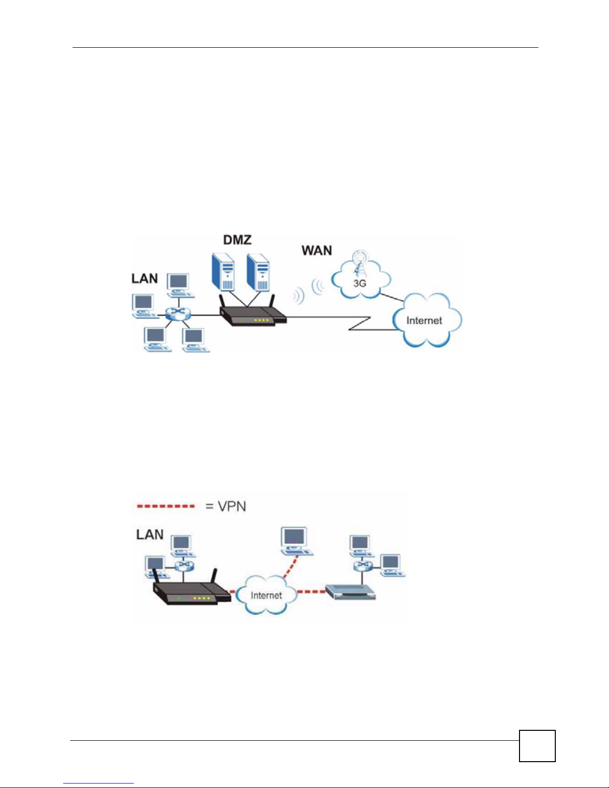
Chapter 1 Getting to Know Your LAN-Cell 2
1.4.2 Redundant Secure Broadband Internet Access via Ethernet or Cellular
Connect the LAN-Cell’s Ethernet WAN port to your existing Internet access gateway
(company network, or your cable or DSL modem for example). Connect computers or servers
to the LAN, DMZ or WLAN ports for shared Internet access.
With both the primary WAN (physical WAN port) and 3G WAN connections enabled, you
can set one of the WAN connections as an automatic fail-over backup connection or use load
balancing to improve quality of service and maximize bandwidth utilization.
The LAN-Cell guarantees not only high speed Internet access, but secure internal network
protection and traffic management as well.
Figure 2 Redundant Internet Access via Ethernet or Cellular
1.4.3 VPN Application
The LAN-Cell’s built-in VPN feature is an ideal cost-ef fective way to securely connect branch
offices, business partners and telecommuters over the Internet without the need (and expense)
for leased lines between sites. You can make connections via the LAN-Cell’s cellular, wired
WAN, or dial-backup interfaces to ensure VPN connectivity regardles s of the communication
service available.
Figure 3 VPN Application
LAN-Cell 2 User’s Guide
29
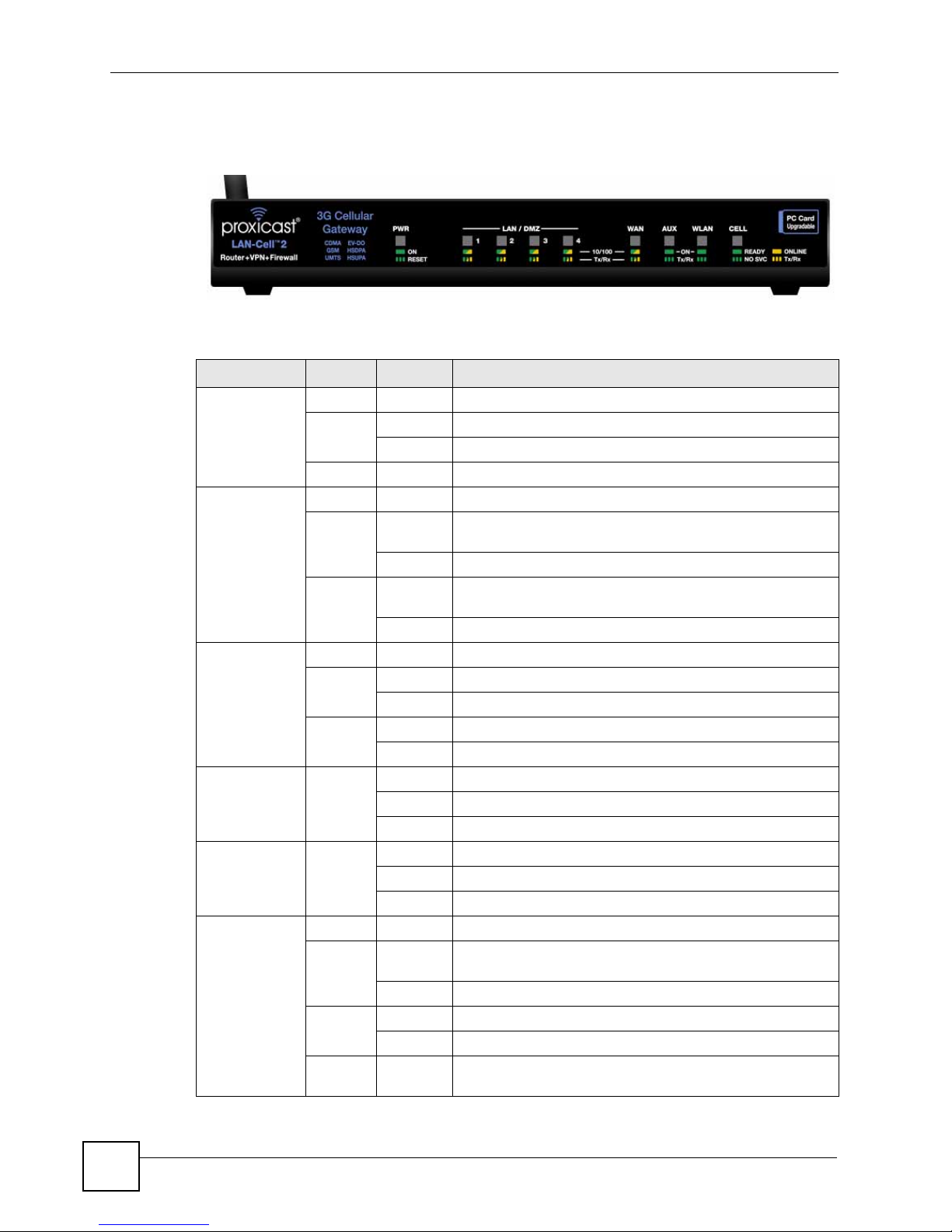
Chapter 1 Getting to Know Your LAN-Cell 2
1.5 Front Panel Indicators
Figure 4 Front Panel
The following table describes the LAN-Cell’s front panel indicator lights.
Table 1 Front Panel Lights
LED COLOR STATUS DESCRIPTION
PWR Off The LAN-Cell is turned off.
Green On The LAN-Cell is ready and running.
Flashing Power-on Self Test is in progress. (approximately 60 sec)
Red On The power to the LAN-Cell is too low.
LAN/DMZ 1-4 Off The LAN/DMZ is not connected.
Green On The LAN-Cell has a successful 10Mbps Ethernet
Flashing The 10M LAN is sending or receiving packets.
Orange On The LAN-Cell has a successful 100Mbps Ethernet
Flashing The 100M LAN is sending or receiving packets.
WAN Off The WAN connection is not ready, or has failed.
Green On The LAN-Cell has a successful 10Mbps WAN connection.
Flashing The 10M WAN is sending or receiving packets.
Orange On The LAN-Cell has a successful 100Mbps WAN connection.
Flashing The 100M WAN is sending or receiving packets.
AUX Green Off The dial backup port is not connected to a remote server.
On The dial backup port is connected to a remote server.
Flashing The dial backup port is sending or receiving packets.
WLAN Green Off The wireless LAN is not ready, or has failed.
On The wireless LAN is ready.
Flashing The wireless LAN is sending or receiving packets.
CELL Off There is no 3G card inserted in the LAN-Cell.
Green Flashing 3G card is initializing OR is not registered on the carrier
On A 3G card ready to make a connection (dial).
Orange On The 3G WAN connection is established.
Flashing The 3G WAN is sending or receiving packets.
Green/
Orange
Flashing Cellular signal strength or quality is Poor. Connections may
connection.
connection.
network OR there is no compatible cellular service available.
be unreliable.
30
LAN-Cell 2 User’s Guide

1.6 Rear Panel Connections
Figure 5 Rear Panel
The following table describes the LAN-Cell 2’s rear panel connections.
Table 2 Rear Panel Connections
LABEL DESCRIPTION
PWR Connect the included 12V DC power adapter to this power jack.
RESET To erase all user-entered settings, press & hold the reset button with a small object
such as a paperclip for approximately 10 seconds until the PWR LED begins to
flash. This returns the LAN-Cell to its factory default settings (LAN IP = 192.168.1.1
Password = 1234).
LAN/DMZ 1-4 Connect computer equipment to these ports with Ethernet cables. These ports are
auto-negotiating (can connect at 10 or 100 Mbps) and auto-sensing (automatically
adjust to the type of Ethernet cable you use, straight-through or crossover). Set the
ports as LAN or DMZ in the web configurator.
WAN Connect a cable/DSL modem or other 10/100 Ethernet-based WAN equipment to
AUX Connect an analog modem's RS-232 interface to the AUX port using the Black
CONSOLE Use the Blue
WLAN Attach the supplied cylindrical Wi-Fi antenna to this SMA-RP (reverse polarity)
3G CARD
SLOT
this port.
backup cable. The AUX port is used only to provide modem dial-backup support for
the wired WAN and Ce ll u l ar Mo de m in te rfaces. The default AUX port
communication parameters are: 115200 bps, no parity, 8 data bits, 1 stop bit,
hardware flow control..
serial cable to connect a terminal or PC-terminal emulation program to
the LAN-Cell for diagnostic access. The default Console Port communication
parameters are: 9600 bps, no parity, 8 data bits, 1 stop bit, no flow control.
connector if you will be using the LAN-Cell's integrated 802.11 a/b/g/ access point.
Attaching other types of antennas (such antennas with standard SMA, TNC or
FME connectors) to this jack may damage the antennas and/or WLAN antenna
jack!
Insert an activated 3G PC-Card cellular modem into the slot on the right side of the
LAN-Cell. Always power off the LAN-Cell before inserting or removing PC-
Cards, otherwise damage to the LAN Cell or the PC-Card may result.
Chapter 1 Getting to Know Your LAN-Cell 2
dial
LAN-Cell 2 User’s Guide
31

Chapter 1 Getting to Know Your LAN-Cell 2
1.7 Card-Lock
The LAN-Cell 2's Card-Lock system provides a mechanism for securing the PC Card modem
to prevent it from coming loose in mobile applications.
1 Insert a cable-tie through the two Card-Lock brackets above and below the PC-Card slot
(Figure 6) leaving enough slack to accommodate the portion of the PC-Card that extends
outside of the LAN-Cell.
Figure 6 Card-Lock Step 1
2 Rotate the loop toward the front of the LAN-Cell (Figure 7).
Figure 7 Card-Lock Step 2
32
LAN-Cell 2 User’s Guide

Chapter 1 Getting to Know Your LAN-Cell 2
3 Insert the PC-Card modem into the card slot, keeping the cable-tie loop toward the front
of the LAN-Cell (Figure 8).
Figure 8 Card-Lock Step 3
4 Once the PC-Card is inserted, slide the loop over the protruding end of the card and pull
the bottom of the cable-tie straight down to tighten the loop against the card (Figure 9).
Figure 9 Card-Lock Step 4
LAN-Cell 2 User’s Guide
33

Chapter 1 Getting to Know Your LAN-Cell 2
5 Bring the bottom of the cable-tie up to secure it with the cable-tie lock (Figure 10).
Figure 10 Card-Lock Step 5
6 Tighten the cable-tie against the PC Card (Figure 11).
Figure 11 Card-Lock Step 6
You may also wish to lock the PC Card's external antenna "pig-tail" cable inside the cable-tie
loop to minimize movement of the antenna cable.
34
LAN-Cell 2 User’s Guide

CHAPTER 2
Introducing the Web
Configurator & Home Screen
This chapter describes how to access the LAN-Cell web configurator and provides an
overview of its screens.
2.1 Web Configurator Overview
The web configurator is an HTML-based management interface that allows easy LAN-Cell
setup and management via Internet browser. Use Internet Explorer 6.0 and later or Netscape
Navigator 7.0 and later versions. The recommended screen resolution is 1024 by 768 pixels.
In order to use the web configurator you need to allow:
• Web browser pop-up windows from your device. Web pop-up blocking is enabled by
default in Windows XP SP (Service Pack) 2.
• JavaScripts (enabled by default).
• Java permissions (enabled by default).
See Appendix A on page 583 if you want to make sure these functions are allowed in Internet
Explorer or Netscape Navigator.
2.2 Accessing the LAN-Cell Web Configurator
" By default, the packets from WLAN to WLAN/LAN-Cell are dropped and users
cannot configure the LAN-Cell wirelessly. We do not recommend configuring
the LAN-Cell via a WLAN connection.
1 Make sure your LAN-Cell hardware is properly connected and prepare your computer/
computer network to connect to the LAN-Cell (refer to the Quick Start Guide).
2 Launch your web browser.
3 Type "192.168.1.1" as the URL. The LAN-Cell Login screen will appear Figure 12)
LAN-Cell 2 User’s Guide
35

Chapter 2 Introducing the Web Configurator & Home Screen
Figure 12 Web Configurator Login Screen
4 Type "1234" (default) as the password and click Login.
5 You should see a screen (Figure 13) asking you to change your password (highly
recommended). T ype a new password (and retype it to confirm) and click Apply or click
Ignore.
Figure 13 Change Password Screen
6 Click Apply in the Replace Certificate screen (Figure 14) to create a certificate using
your LAN-Cell’s MAC address that will be specific to this device.
" If you do not replace the default certificate here or in the CERTIFICATES
screen, this screen displays every time you access the web configurator.
Figure 14 Replace Certificate Screen
7 You should now see the HOME screen (see Figure 16 on page 41).
36
LAN-Cell 2 User’s Guide

Chapter 2 Introducing the Web Configurator & Home Screen
C
D
B
A
" The management session automatically times out when the time period set in
the Administrator Inactivity Timer field expires (default five minutes). Simply
log back into the LAN-Cell if this happens to you.
2.3 Navigating the LAN-Cell Web Configurator
The following summarizes how to navigate the web configurator from the HOME screen.
Figure 15 HOME Screen
As illustrated above, the main screen is divided into these parts:
• A - Title Bar
• B - Navigation Panel
• C - Main Window
• D - Status Bar
2.3.1 Title Bar
The title bar contains the Help icon in the upper right corner.
LAN-Cell 2 User’s Guide
37

Chapter 2 Introducing the Web Configurator & Home Screen
2.3.2 Navigation Panel
The following table describes the sub-menus on the left side navigation panel.
Table 3 Screens Summary
LINK TAB FUNCTION
HOME This screen shows the LAN-Cell’s general device and network
status information. Use this screen to access the wizards,
statistics and DHCP table.
NETWORK
LAN LAN Use this screen to configure LAN DHCP and TCP/IP settings.
Static DHCP Use this screen to assign fixed IP addresses on the LAN.
IP Alias Use this screen to partition your LAN interface into subnets.
Port Roles Use this screen to change the LAN/DMZ/WLAN port roles.
WAN General This screen allows you to configure load balancing, route priority
and traffic redirect properties.
WAN Use this screen to configure the WAN connection for Internet
Cellular Use this screen to configure the Cellular connection for Internet
Traffic
Redirect
Dial Backup Use this screen to configure the backup WAN dial-up connection.
DMZ DMZ Use this screen to configure your DMZ connection.
Static DHCP Use this screen to assign fixed IP addresses on the DMZ.
IP Alias Use this screen to partition your DMZ interface into subnets.
Port Roles Use this screen to change the LAN/DMZ/WLAN port roles on the
WLAN WLAN Use this screen to confi gure your WLAN connection.
Static DHCP Use this screen to assign fixed IP addresses on the WLAN.
IP Alias Use this screen to partition your WLAN interface into subnets.
Port Roles Use this screen to change the LAN/DMZ/WLAN port roles on the
WIRELESS
CELLULAR Use this screen to configure the Cellular connection for Internet
Wi-Fi Wi-Fi
Configuration
Security Use this screen to configure the WLAN security settings.
MAC Filter Use this screen to change MAC filter settings on the LAN-Cell
SECURITY
access.
access.
Use this screen to configure your traffic redirect properties and
parameters.
LAN-Cell.
LAN-Cell.
access.
Use this screen to configure the internal Wi-Fi Access Point
settings.
38
LAN-Cell 2 User’s Guide

Chapter 2 Introducing the Web Configurator & Home Screen
Table 3 Screens Summary (continued)
LINK TAB FUNCTION
FIREWALL Default Rule Use this screen to activate/deactivate the firewall and the direction
of network traffic to which to apply the rule
Rule Summary This screen shows a summary of the firewall rules, and allows you
to edit/add a firewall rule.
Anti-Probing Use this screen to change your anti-probing settings.
Threshold Use this screen to configure the threshold for DoS attacks.
Service Use this screen to configure custom servic es.
VPN WIZARD Use this Wizard to be prompted through the process of setting up
a basic IPSec VPN connection.
VPN CONFIG VPN Rules
(IKE)
VPN Rules
(Manual)
SA Monitor Use this screen to display and manage active VPN connections.
Global Setting Use this screen to configure the IPSec timer settings.
CERTIFICATES My Certificates Use this screen to view a summary list of certificates and manage
Trusted CAs Use this screen to view and manage the list of the trusted CAs.
Trusted
Remote Hosts
Directory
Servers
AUTH SERVER Local User
Database
RADIUS Configure this screen to use an external server to authenticate
ADVANCED
NAT NAT Overview Use this screen to enable NAT.
Address
Mapping
Port
Forwarding
Port
Triggering
DNS System Use this screen to configure the address and name server
Cache Use this screen to configure the DNS resolution cache.
DHCP Use this screen to confi gure LAN/DMZ/WLAN DNS information.
DDNS Use this screen to set up dynamic DNS.
Use this screen to configure VPN connections using IKE key
management and view the rule summary.
Use this screen to configure VPN connections using manual key
management and view the rule summary.
certificates and certification requests.
Use this screen to view and manage the certificates belonging to
the trusted remote hosts.
Use this screen to view and manage the list of the directory
servers.
Use this screen to configure the local user account(s) on the LAN-
Cell.
wireless and/or VPN users.
Use this screen to configure network address translation mapping
rules.
Use this screen to configure servers behind the LAN-Cell.
Use this screen to change your LAN-Cell’s port triggering settings.
records.
LAN-Cell 2 User’s Guide
39

Chapter 2 Introducing the Web Configurator & Home Screen
Table 3 Screens Summary (continued)
LINK TAB FUNCTION
REMOTE
MGMT
STATIC ROUTE IP Static Route Use this scre en to configure IP static routes.
POLICY ROUTE Policy Route
BW MGMT Summary Use this screen to enable bandwidth management on an interface.
Custom APP Custom App Use th is screen to specify port numbers for the LAN-Cell to
ALG ALG Use this screen to allow certain applications to pass through the
LOGS View Log Use this screen to view the logs for the categories that you
MAINTENANCE General This screen contains administrative.
LOGOUT Click this label to exit the web configurator.
WWW Use this screen to configure through which interface(s) and from
which IP address(es) users can use HTTPS or HTTP to manage
the LAN-Cell.
SSH Use this screen to configure through which interface(s) and from
which IP address(es) users can use Secure Shell to manage the
LAN-Cell.
TELNET Use this screen to configure through which interface(s) and from
which IP address(es) users can use Telnet to manage the LAN-
Cell.
FTP Use this screen to configure through which interface(s) and from
which IP address(es) users can use FTP to access the LAN-Cell.
SNMP Use this screen to configure your LAN-Cell’s settings for Simple
DNS Use this screen to configure through which interface(s) and from
Summary
Class Setup Use this screen to set up the bandwidth classes.
Monitor Use this screen to view the LAN-Cell ’s bandwidth usage and
Log Settings Use this screen to change your LAN-Cell’s log settings.
Password Use this screen to change your password.
Time and Date Use this screen to change your LAN-Cell’s time and date.
F/W Upload Use this screen to upload firmware to your LAN-Cell
Backup &
Restore
Restart This screen allows you to reboot the LAN-Cell without turning the
Diagnostics Use this scre en to have the LAN-Cell generate and send
Network Management Protocol management.
which IP address(es) users can send DNS queries to the LAN-
Cell.
Use this screen to view a summary list of all the policies and
configure policies for use in IP policy routing.
allotments.
monitor for FTP, HTTP, SMTP, POP3, H323, and SIP traffic.
LAN-Cell.
selected.
Use this screen to backup and restore the configuration or reset
the factory defaults to your LAN-Cell.
power off.
diagnostic files by e-mail and/or the console port.
2.3.3 Main Window
The main window shows the screen you select in the navigation panel. It is discussed in more
detail in the rest of this document.
40
LAN-Cell 2 User’s Guide

Right after you log in, the HOME screen is displayed.
2.3.4 HOME Screen
This screen displays general status information about the LAN-Cell.
Figure 16 Web Configurator HOME Screen
Chapter 2 Introducing the Web Configurator & Home Screen
The following table describes the labels in this screen.
Table 4 Web Configurator HOME Screen
LABEL DESCRIPTION
Automatic Refresh
Interval
Refresh Click this button to update the status screen statistics immediately.
System Information
System Name This is the System Name you enter in the MAINTENANCE > General screen. It
Model This is the model name of your LAN-Cell.
Bootbase Version This is the bootbase version and the date created.
Firmware Version This is the ProxiOS Firmware version and the date created. ProxiOS is
Up Time This field displays how long the LAN-Cell has been running since it last started
Select a number of seconds or None from the drop-down list box to update all
screen statistics automatically at the end of every time interval or to not update
the screen statistics.
is for identification purposes. Click the field label to go to the screen where you
can specify a name for this LAN-Cell.
Proxicast's proprietary Network Operating System design. Click the field label to
go to the screen where you can upload a new firmware file.
up. The LAN-Cell starts up when you turn it on, when you restart it
(MAINTENANCE > Restart), or when you reset it (see Section A. on page 50).
LAN-Cell 2 User’s Guide
41

Chapter 2 Introducing the Web Configurator & Home Screen
Table 4 Web Configurator HOME Screen (continued)
LABEL DESCRIPTION
System Time This field displays your LAN-Cell’s present date (in yyyy-mm-dd format) and time
(in hh:mm:ss format) along with the difference from the Greenwich Mean Time
(GMT) zone. The difference from GMT is based on the time zone. It is also
adjusted for Daylight Saving Time if you set the LAN-Cell to use it. Click the field
label to go to the screen where you can modify the LAN-Cell’s date and time
settings.
Firewall This displays whether or not the LAN-Cell’s firewall is activated. Click the field
label to go to the screen where you can turn the firewall on or off.
System Resources
Flash The first number shows how many megabytes of the flash the LAN-Cell is using.
Memory The first number shows how many megabytes of the heap memory the LAN-Cell
is using. Heap memory refers to the memory that is not used by ProxiOS and is
thus available for running processes like NAT, VPN and the firewall.
The second number shows the LAN-Cell's total heap memory (in megabytes).
The bar displays what percent of the LAN-Cell's heap memory is in use. The bar
turns from green to red when the maximum is being approached.
Sessions The first number shows how many sessions are currently open on the LAN-Cell.
CPU This field displays what percentage of the LAN-Cell’s processing ability is
Interfaces This is the port type.
Status For the LAN, DMZ and WLAN ports, this displays the port speed and duplex
IP/Netmask This shows the port’s IP address and subnet mask.
This includes all sessions that are currently traversing the LAN-Cell, terminating
at the LAN-Cell or Initiated from the LAN-Cell
The second number is the maximum number of sessions that can be open at one
time.
The bar displays what percent of the maximum number of sessions is in use. The
bar turns from green to red when the maximum is being approached.
currently used. When this percentage is close to 100%, the LAN-Cell is running at
full load, and the throughput is not going to improve anymore. If you want some
applications to have more throughput, you should turn off other applications (for
example, using bandwidth management.
Click "+" to expand or "-" to collapse the IP alias drop-down lists.
Hold your cursor over an interface’s label to display the interface’s MAC Address.
Click an interface’s label to go to the screen where you can configure settings for
that interface.
setting. Ethernet port connections can be in half-duplex or full-du plex mode. Full-
duplex refers to a device's ability to send and receive simultaneously, while half-
duplex indicates that traffic can flow in only one direction at a time. The Ethernet
port must use the same speed or duplex mode setting as the peer Ethernet port in
order to connect.
For the WAN interface(s) and the Dial Backup port, it displays the port speed and
duplex setting if you’re using Ethernet encapsulation or the remote node name
(configured through the SMT) for a PPP connection and Down (line is down or
not connected), Idle (line (ppp) idle), Dial (starting to trigger a call) or Drop
(dropping a call) if you’re using PPPoE encapsulation.
42
LAN-Cell 2 User’s Guide

Chapter 2 Introducing the Web Configurator & Home Screen
Table 4 Web Configurator HOME Screen (continued)
LABEL DESCRIPTION
IP Assignment For the WAN, if the LAN-Cell gets its IP address automatically from an ISP, this
displays DHCP client when you’re using Ethernet encaps ulation and IPCP Client
when you’re using PPPoE or PPTP encapsulation. Static displays if the WAN
port is using a manually entered static (fixed) IP address.
For the LAN, WLAN or DMZ, DHCP server displays when the LAN-Cell is set to
automatically give IP address information to the computers connected to the LAN.
DHCP relay displays when the LAN-Cell is set to forward IP address assignment
requests to another DHCP server. Static displays if the LAN port is using a
manually entered static (fixed) IP address. In this case, you must have another
DHCP server on your LAN, or else the computers must be manually configured.
For the dial backup port, this shows N/A when dial backup is disabled and IPCP
client when dial backup is enabled.
Renew If you are using Ethernet encapsulation and the WAN port is configured to get the
IP address automatically from the ISP, click Renew to release the WAN port’s
dynamically assigned IP address and get the IP address afresh. Click Dial to dial
up the PPTP, PPPoE or dial backup connection. Click Drop to disconnect the
PPTP, PPPoE, 3G WAN or dial backup connection.
Cellular Interface Status
The fields below shows up on the LAN-Cell with a 3G card inserted.
Cellular
Connection Status
Service Provider This displays the name of your network service provider or Limited Service when
Roaming Network Name of 3G Operator currently providing service when roaming off of the 3G
Signal Strength This displays the strength of the signal. The signal strength mainly depends on
Last Connection
Up Time
Tx Bytes This displ ays the total number of data frames transmitted.
Rx Bytes This displays the total number of data frames received.
Remaining Budget
Bytes
Remaining Budget
Time
Cellular Card
Manufacturer
Cellular Card
Model
This displays Down when the 3G connection is down or not activated.
This displays Idle when the 3G connection is idle.
This displays Init when the LAN-Cell is initializing the 3G card.
This displays Drop when the LAN-Cell is dropping a call.
This also displays whether the LAN-Cell is connected to a UMTS/HSDPA, GPRS/
EDGE or CDMA/EV-DO network.
the signal strength is too low.
card’s “Home” network.
the antenna output power and the distance between your LAN-Cell and the
service provider’s base station.
This displays how long the 3G connection has been up.
This field is available only when you enable budget control in the Cellular screen.
This shows how much data (in bytes) can still be transmitted through the cellular
connection before the LAN-Cell takes the actions you specified in the Cellular
screen.
Click the reset link and OK in the pop-up screen to clear all counters in the
Remaining Budget Bytes and Remaining Budget Time fields.
This field is available only when you enable budget control in the Cellular screen.
This shows the amount of time (in hours and minutes) the cellular connection can
still be used before the LAN-Cell takes the actions you specified in the Cellular
screen.
This displays the manufacturer of your 3G card.
This displays the model name of your 3G card.
LAN-Cell 2 User’s Guide
43

Chapter 2 Introducing the Web Configurator & Home Screen
Table 4 Web Configurator HOME Screen (continued)
LABEL DESCRIPTION
Cellular Card
Firmware Revision
Cellular Card IMEI This fie ld is available only when you insert a GSM (Global System for Mobile
SIM Card IMSI This field is available only when you insert a GSM or UMTS cellular card.
Cellular Card ESN This field is available only when you insert a CDMA (Code Division Multiple
Enter PIN code If the PIN code you specified in the Cellular screen is not the right one for the card
PUK Code If you enter the PIN code incorrectly three times, the SIM card will be blocked by
New PIN Code Configure a PIN code for the SIM card. You can specify any four to eight digits to
Reset budget
counters, resume
budget control
Resume budget
control
Disable budget
control
Enter modem
unlock code
This displays the version of the firmware currently used in the 3G card.
Communications) or UMTS (Universal Mobile Telecommunications System)
cellular card.
This displays the International Mobile Equipment Identity (IMEI) which is the
serial number of the GSM or UMTS cellular card. The IMEI is a unique 15-digit
number used to identify a mobile device.
This displays the International Mobile Subscriber Identity (IMSI) stored in the SIM
(Subscriber Identity Module) card. The SIM card is installed in a mobile device
and used for authenticating a customer to the carrier network. The IMSI is a
unique 15-digit number used to identify a user on a network.
Access) cellular card.
This shows the ESN (Electronic Serial Number) of the inserted CDMA cellular
card in decimal and (hexadecimal) notation. The ESN is the serial number of a
CDMA cellular card and is similar to the IMEI on a GSM or UMTS cellular card.
you inserted, this field displays allowing you to enter the correct PIN code. Enter
the PIN code (four to eight digits) for the inserted cellular card.
your ISP and you cannot use the account to access the Internet. You should get
the PUK (Personal Unblocking Key) code (four to eight digits) from your ISP.
Enter the PUK code to enable the SIM card. If an incorrect PUK code is entered
10 times, the SIM card will be disabled permanently. You then need to contact
your ISP for a new SIM card.
have a new PIN code or enter the previous PIN code.
This field displays if you have enabled budget control but insert a cellular card
with a different user account from the one for which you configured budget
control.
Select this option to have the LAN-Cell do budget calculation starting from 0 but
use the previous settings.
This field displays if you have enabled budget control but insert a cellular card
with a different user account from the one for which you configured budget
control.
Select this option to have the LAN-Cell keep the existing statistics and continue
counting.
This field displays if you have enabled budget control but insert a cellular card
with a different user account from the one for which you configured budget
control.
Select this option to disable budget control.
If you want to enable and configure new budget control settings for the new user
account, go to the Cellular screen.
The LAN-Cell keeps the existing statistics if you do not change the budget control
settings. You could reinsert the original card and enable budget control to have
the LAN-Cell continue counting the budget control statistics.
This field only displays when you insert a cellular card and the internal modem on
the cellular card is blocked.
Enter a key to enable the internal modem on your cellular card. By default, the
key is the last four digits of your phone number used to dial up the cellular
connection. Otherwise, you need to get the key from your service provider.
44
LAN-Cell 2 User’s Guide

Chapter 2 Introducing the Web Configurator & Home Screen
Table 4 Web Configurator HOME Screen (continued)
LABEL DESCRIPTION
Wi-Fi Information
Wi-Fi status This displays whether or not the wireless LAN card is activated.
SSID This displays a descriptive name used to identify the LAN-Cell in the wireless
LAN.
Bridge To This displays whether the wireless LAN card is used as part of the LAN, DMZ or
WLAN.
802.11 Mode This displays the wireless standard (802.11a, 802.11b, 802.11g or 802.11b+g) of
the wireless LAN.
Channel This displays the radio channel the LAN-Cell is currently using for the wireless
Security Mode This shows the type of wireless security the LAN-Cell is using.
# of Associated
Clients
ALERTS
Latest Alerts This table displays the five most recent alerts recorded by the LAN-Cell. You can
Date/Time This is the date and time the alert was recorded.
Message This is the reason for the alert.
System Status
Port Statistics Click Port Statistics to see router performance statistics such as the number of
DHCP Table Click DHCP Table to show current DHCP client information.
VPN Click VPN to display the active VPN connections.
Bandwidth Click Bandwidth to view the LAN-Cell’s bandwidth usage and allotments.
LAN.
This shows the number of the wireless client(s) connected to the LAN-Cell.
see more information in the View Log screen, such as the source and destination
IP addresses and port numbers of the incoming packets.
packets sent and number of packets received for each port.
2.3.5 Port Statistics
Click Port Statistics in the HOME screen. Read-only information here includes port status
and packet specific statistics. The Poll Interval(s) field is configurable.
LAN-Cell 2 User’s Guide
45

Chapter 2 Introducing the Web Configurator & Home Screen
Figure 17 HOME > Show Statistics
The following table describes the labels in this screen.
Table 5 HOME > Show Statistics
LABEL DESCRIPTION
Click the icon to display the chart of throughput statistics.
Port These are the LAN-Cell’s interfaces.
Status For the WAN interface(s) and the Dial Backup port, this displays the port speed and
TxPkts This is the number of transmitted packets on this port.
RxPkts This is the number of received packets on this port.
Tx B/s This displays the transmission speed in bytes per second on this port.
Rx B/s This displays the reception speed in bytes per second on this port.
Up Time This is the total amount of time the line has been up.
System Up Time This is the total time the LAN-Cell has been on.
Automatic
Refresh Interval
Refresh Click this button to update the screen’s statistics immediately.
duplex setting if you’re using Ethernet encapsulation or the remote node name for a
PPP connection and Down (line is down or not connected), Idle (line (ppp) idle),
Dial (starting to trigger a call) or Drop (dropping a call) if you’re using PPPoE
encapsulation.
For the LAN, DMZ and WLAN ports, this displays the port speed and duplex setting.
For the WLAN card, this displays the transmission rate when WLAN is enabled or
Down when WLAN is disabled.
Select a number of seconds or None from the drop-down list box to update all
screen statistics automatically at the end of every time interval or to not update the
screen statistics.
2.3.6 Show Statistics: Line Chart
Click the icon in the Show Statistics screen. This screen shows you a line chart of each port’s
throughput statistics.
46
LAN-Cell 2 User’s Guide

Chapter 2 Introducing the Web Configurator & Home Screen
Figure 18 HOME > Show Statistics > Line Chart
The following table describes the labels in this screen.
Table 6 HOME > Show Statistics > Line Chart
LABEL DESCRIPTION
Click the icon to go back to the Show Statistics screen.
Port Select the check box(es) to display the throughput statistics of the corresponding
B/s Specify the direction of the traffic for which you want to show throughput statistics in
Throughput
Range
interface(s).
this table.
Select Tx to display transmitted traffic throughput statistics and the amount of traffic
(in bytes). Select Rx to display received traffic throughput statistics and the amount
of traffic (in bytes).
Set the range of the throughput (in B/s, KB/s or MB/s) to display.
Click Set Range to save this setting back to the LAN-Cell.
2.3.7 DHCP Table Screen
DHCP (Dynamic Host Configuration Protocol, RFC 2131 and RFC 2132) allows individual
clients to obtain TCP/IP configuration at start-up from a server. You can configure the LANCell as a DHCP server or disable it. When configured as a server, the LAN-Cell provides the
TCP/IP configuration for the clients. If DHCP service is disabled, you must have another
DHCP server on your LAN, or else the computer must be manually configured.
Click Show DHCP Table in the HOME sc reen. Read-only information here relates to your
DHCP status. The DHCP table shows current DHCP client information (including IP
Address, Host Name and MAC Addr ess) of all network clients using the L AN-Cell’s DHCP
server.
LAN-Cell 2 User’s Guide
47

Chapter 2 Introducing the Web Configurator & Home Screen
Figure 19 HOME > DHCP Table
The following table describes the labels in this screen.
Table 7 HOME > DHCP Table
LABEL DESCRIPTION
Interface Select LAN, DMZ or WLAN to show the current DHCP client information for the
# This is the index number of the host computer.
IP Address This field displays the IP address relative to the # field listed above.
Host Name This field displays the computer host name.
MAC Address The MAC (Media Access Control) or Ethernet address on a LAN (Local Area
Reserve Select the check box in the heading row to automatically select all check boxes or
Refresh Click Refresh to reload the DHCP table.
specified interface.
Network) is unique to your computer (six pairs of hexadecimal notation).
A network interface card such as an Ethernet adapter has a hardwired address that is
assigned at the factory. This address follows an industry standard that ensures no
other adapter has a similar address.
select the check box(es) in each entry to have the LAN-Cell always assign the
selected entry(ies)’s IP address(es) to the corresponding MAC address(es) (and host
name(s)). You can select up to 128 entries in this table. After you click Apply, the
MAC address and IP address also display in the corresponding LAN, DMZ or WLAN
Static DHCP screen (where you can edit them).
2.3.8 VPN Status
Click VPN in the HOME screen. This screen displays read-only information about the active
VPN connections. The Poll Interval(s) field is configurable. A Security Association (SA) is
the group of security settings related to a specific VPN tunnel.
48
LAN-Cell 2 User’s Guide

Chapter 2 Introducing the Web Configurator & Home Screen
Figure 20 HOME > VPN Status
The following table describes the labels in this screen.
Table 8 HOME > VPN Status
LABEL DESCRIPTION
# This is the security association index number.
Name This field displays the identificati on name for this VPN policy.
Local Network This field displays the IP address of the computer using the VPN IPSec feature of
your LAN-Cell.
Remote Network This field displays IP address (in a range) of computers on the remote network
behind the remote IPSec router.
Encapsulation This field displays Tunnel or Transport mode.
IPSec Algorithm This field displays the security protocols used for an SA.
Both AH and ESP increase LAN-Cell processing requirements and communications
latency (delay).
Automatic
Refresh Interval
Refresh Click this button to update the screen’s statistics immediately.
Select a number of seconds or None from the drop-down list box to update all
screen statistics automatically at the end of every time interval or to not update the
screen statistics.
2.3.9 Bandwidth Monitor
Click Bandwidth in the HOME screen to display the bandwidth monitor. This screen displays
the device’s bandwidth usage and allotments.
LAN-Cell 2 User’s Guide
49

Chapter 2 Introducing the Web Configurator & Home Screen
Figure 21 Home > Bandwidth Monitor
The following table describes the labels in this screen.
Table 9 ADVANCED > BW MGMT > Monitor
LABEL DESCRIPTION
Interface Select an interface from the drop-down list box to view the bandwidth usage
Class This field displays the name of the bandwidth class.
Budget (kbps) This field displays the amount of bandwidth allocated to the bandwidth class.
Current Usage (kbps) This field displays the amount of bandwidth that each bandwidth class is
Automatic Refresh
Interval
Refresh Click this button to update the screen’s statistics immediately.
of its bandwidth classes.
A Default Class automatically displays for all the bandwidth in the Root
Class that is not allocated to bandwidth classes. If you do not enable
maximize bandwidth usage on an interface, the LAN-Cell uses the bandwidth
in this default class to send traffic that does not match any of the bandwidth
classes.
using.
Select a number of seconds or None from the drop-down list box to update all
screen statistics automatically at the end of every time interval or to not
update the screen statistics.
A
A. If you allocate all the root class’s bandwidth to the bandwidth classes, the default class still displays a budget of 2
kbps (the minimum amount of bandwidth that can be assigned to a bandwidth class).
2.3.10 Status Bar
The Status Bar area displays system confirmation and error messages as you navigate through
the Web Configurator. Whenever clicking “Apply” to save configuration parameters, be sure
to wait for the Status Bar message “Configuration updated successfully” before moving to
the next screen.
50
LAN-Cell 2 User’s Guide

2.4 Resetting the LAN-Cell
If you forget your password or cannot access the web configurator , you will need to reload the
factory-default configuration file or use the RESET button on the back of the LAN-Cell.
Uploading this configuration file replaces the current configuration file with the factorydefault configuration file. This means that you will lose all configurations that you had
previously and the speed of the console port will be reset to the default of 9600bps with 8 data
bit, no parity, one stop bit and flow control set to none. The password will be reset to 1234,
also.
Make sure the SYS LED is on (not blinking) before you begin this procedure.
1 Press the RESET button for ten seconds, and then release it. If the SYS LED begins to
blink, the defaults have been restored and the LAN-Cell restarts. Otherwise, go to step 2.
2 Turn the LAN-Cell off.
3 While pressing the RESET button, turn the LAN-Cell on.
4 Continue to hold the RESET button. The SYS LED will begin to blink and flicker very
quickly after about 20 seconds. This indicates that the defaults have been restored and
the LAN-Cell is now restarting.
Release the RESET button and wait for the LAN-Cell to finish restarting.
Chapter 2 Introducing the Web Configurator & Home Screen
LAN-Cell 2 User’s Guide
51

Chapter 2 Introducing the Web Configurator & Home Screen
52
LAN-Cell 2 User’s Guide

CHAPTER 3
Tutorials: 3G Modem Setup &
VPN Wizard
This chapter describes how to set up a 3G Cellular PC-Card modem WAN connection and
how to configure a basic VPN using the VPN Wizard and firewall security settings.
3.1 Setting Up a 3G WAN Connection
3.1.1 Inserting a 3G PC-Card
T o enable and use the 3G WAN connection, you need to insert a 3G PC-Card in the LAN-Cell.
1 Turn the LAN-Cell off before you install or remove a 3G card.
1 After obtaining a 3G PC-Card modem from your cellular service provider, ensure that it
is properly configured and activated on their network by using the PC-Card in a
Windows laptop to make a 3G network connection. PC-Card firmware updates and
device activation must be done using the software tools provided by your carrier or the
PC-Card manufacturer.
1 Make sure the LAN-Cell is off before inserting or removing a card (to avoid damage).
2 Slide the connector end of the 3G card firmly and completely into the slot.
3 Power on the LAN-Cell.
" The LAN-Cell supports a specific list of 3G Cellular PC-Card modems
including devices for GSM, GPRS, EDGE, HSDPA, HSUPA, UMTS, CDMA,
1xRTT and EV-DO carrier networks worldwide. ExpressCard modems are
supported using a PC-Card to ExpressCard adapter cradle.
Refer to the firmware Release Notes or the Proxicast Support Web site for the
list of 3G PC-Cards supported in your firmware version. Support for additional
3G cards is being added continuously and may require a firmware upgrade.
LAN-Cell 2 User’s Guide
53

Chapter 3 Tutorials: 3G Modem Setup & VPN Wizard
3.1.2 Configuring 3G WAN Settings
You should already have an activated user account and network access information from the
service provider.
1 Click WIRELESS > Cellular on the LAN-Cell.
2 Make sure that the Cellular interface is Enabled.
3 For GSM networks such as AT&T, T-Mobile, Rogers, Vodafone, Orange, MTN, etc.,
enter the APN (Access Point Name) and phone number (typically *99#) that were
provided by your service provider.
4 For CDMA networks such as Verizon Wireless, Sprint, Alltel, Telus, etc., the APN field
is not required or displayed. The ISP access phone number is typically #777 for CDMA
networks.
5 Select the authentication type used by your service provider. If it was not given, leave
the field at the default (None).
6 If required by your network operator, also enter the user name, password, and PIN code
used for network access. If your service provider didn’t provide this information,
contact your service provider.
7 If you want the Cellular WAN connection to stay connected at all times, select “Always
On”, otherwise indicate how long to wait before the LAN-Cell drops the 3G connection
when no data activity is detected. Note: this will “hang up” the 3G connection and is not
the same as the radio “Dormant State” that 3G PC-Cards go into when not transmitting
data.
8 For WAN IP Address Assignment, select Get Automatically from ISP. This is the
correct setting in most situations, even if your carrier has assigned a “static” IP address
to your 3G card.
9 Click Apply.
54
Figure 22 Tutorial: WIRELESS > Cellular (3G WAN) - CDMA Example
LAN-Cell 2 User’s Guide

Chapter 3 Tutorials: 3G Modem Setup & VPN Wizard
Figure 23 Tutorial: WIRELESS > Cellular (3G WAN) - GSM Example
3.1.3 Checking WAN Connections
1 Go to the web configurator ’s Home screen.
2 In the network status table, make sure the status for Cellular is not Down and there is an
IP address. If the Cellular connection is not up, make sure you have entered the correct
information in the Cellular screen and the signal strength to the service provider’s base
station is not too low.
LAN-Cell 2 User’s Guide
55

Chapter 3 Tutorials: 3G Modem Setup & VPN Wizard
Figure 24 Tutorial: Home
56
LAN-Cell 2 User’s Guide

3.2 VPN Wizard Overview
The web configurator contains a “wizard” feature to help you easily set up a basic IPSec VPN
connnection.
From the left-side navigation menu, select SECURITY then click the VPN Wizard menu
item
to open the VPN Wizard screen. Use this wizard to configure a VPN connection that
uses a pre-shared key. If you want to set the rule to use a certificate, please go to the VPN
Config screens for configuration. See Section 3.2.1 on page 57.
3.2.1 VPN Wizard Gateway Setting
Use this screen to name the VPN gateway policy (IKE SA) and identify the IPSec routers at
either end of the VPN tunnel.
Figure 25 VPN Wizard: Gateway Setting
Chapter 3 Tutorials: 3G Modem Setup & VPN Wizard
The following table describes the labels in this screen.
Table 10 VPN Wizard: Gateway Setting
LABEL DESCRIPTION
Gateway Policy
Property
Name Type up to 32 characters to identify this VPN gateway policy. You may use any
My LAN-Cell Enter the WAN IP address or the domain name of your LAN-Cell or leave the field set
LAN-Cell 2 User’s Guide
character, including spaces, but the LAN-Cell drops trailing spaces.
to 0.0.0.0.
The following applies if the My LAN-Cell field is configured as 0.0.0.0:
When the WAN interface operation mode is set to Active/Passive, the LAN-Cell
uses the IP address (static or dynamic) of the WAN interface that is in use.
When the WAN interface operation mode is set to Active/Active, the LAN-Cell uses
the IP address (static or dynamic) of the primary (highest priority) WAN interface to
set up the VPN tunnel as long as the corresponding WAN or CELL connection is up.
If the corresponding WAN or CELL connection goes down, the LAN-Cell uses the IP
address of the other WAN interface.
If both WAN connections go down, the LAN-Cell uses the dial backup IP address for
the VPN tunnel when using dial backup or the LAN IP address when using traffic
redirect. See the chapter on WAN for details on dial backup and traffic redirect.
57

Chapter 3 Tutorials: 3G Modem Setup & VPN Wizard
Table 10 VPN Wizard: Gateway Setting
LABEL DESCRIPTION
Remote
Gateway
Address
Back Click Back to return to the previous screen.
Next Click Next to continue.
Enter the WAN IP address or domain name of the remote IPSec router (secure
gateway) in the field below to identify the remote IPSec router by its IP address or a
domain name. Set this field to 0.0.0.0 if the remote IPSec router has a dynamic WAN
IP address.
3.2.2 VPN Wizard Network Setting
Use this screen to name the VPN network policy (IPSec SA) and identify the devices behind
the IPSec routers at either end of a VPN tunnel.
Two active SAs cannot have the local and remote IP address(es) both the same. Two active
SAs can have the same local or remote IP address, but not both. You can configure multiple
SAs between the same local and remote IP addresses, as long as only one is active at any time.
Figure 26 VPN Wizard: Network Setting
The following table describes the labels in this screen.
Table 11 VPN Wizard: Network Setting
LABEL DESCRIPTION
Network Policy
Property
Active If the Active check box is selected, packets for the tunnel trigger the LAN-Cell to build
the tunnel.
Clear the Active check box to turn the network policy off. The LAN-Cell does not
apply the policy. Packets for the tunnel do not trigger the tunnel.
Name Type up to 32 characters to identify this VPN network policy. You may use any
character, including spaces, but the LAN-Cell drops trailing spaces.
Network Policy
Setting
58
LAN-Cell 2 User’s Guide

Chapter 3 Tutorials: 3G Modem Setup & VPN Wizard
Table 11 VPN Wizard: Network Setting
LABEL DESCRIPTION
Local Network Local IP addresses must be static and correspond to the remote IPSec router's
configured remote IP addresses.
Select Single for a single IP address. Select Range IP for a specific range of IP
addresses. Select Subnet to specify IP addresses on a network by their subnet
mask.
Starting IP
Address
Ending IP
Address/
Subnet Mask
Remote
Network
Starting IP
Address
Ending IP
Address/
Subnet Mask
Back Click Back to return to the previous screen.
Next Click Next to continue.
When the Local Network field is configured to Single, enter a (static) IP address on
the LAN behind your LAN-Cell. When the Local Network field is configured to Range
IP, enter the beginning (static) IP address, in a range of computers on the LAN behind
your LAN-Cell. When the Local Network field is configured to Subnet, this is a
(static) IP address on the LAN behind your LAN-Cell.
When the Local Network field is configured to Single, this field is N/A. When the
Local Network field is configured to Range IP, enter the end (static) IP address, in a
range of computers on the LAN behind your LAN-Cell. When the Local Network field
is configured to Subnet, this is a subnet mask on the LAN behind your LAN-Cell.
Remote IP addresses must be static and correspond to the remote IPSec router's
configured local IP addresses.
Select Single for a single IP address. Select Range IP for a specific range of IP
addresses. Select Subnet to specify IP addresses on a network by their subnet
mask.
When the Remote Network field is configured to Single, enter a (static) IP address
on the network behind the remote IPSec router. When the Remote Network field is
configured to Range IP, enter the beginning (static) IP address, in a range of
computers on the network behind the remote IPSec router. When the Remote
Network field is configured to Subnet, enter a (static) IP address on the network
behind the remote IPSec router
When the Remote Network field is configured to Single, this field is N/A. When the
Remote Network field is configured to Range IP , enter the end (static) IP address, in
a range of computers on the network behind the remote IPSec router. When the
Remote Network field is configured to Subnet
behind the remote IPSec router.
, enter a subnet mask on the network
3.2.3 VPN Wizard IKE Tunnel Setting (IKE Phase 1)
Use this screen to specify the authentication, encryption and other settings needed to negotiate
a phase 1 IKE SA.
LAN-Cell 2 User’s Guide
59

Chapter 3 Tutorials: 3G Modem Setup & VPN Wizard
Figure 27 VPN Wizard: IKE Tunnel Setting
The following table describes the labels in this screen.
Table 12 VPN Wizard: IKE Tunnel Setting
LABEL DESCRIPTION
Negotiation Mode Select Main Mode for identity protection. Select Aggressive Mode to allow
more incoming connections from dynamic IP addresses to use separate
passwords.
Note: Multiple SAs (security associations) connecting through a
secure gateway must have the same negotiation mode.
Encryption
Algorithm
Authentication
Algorithm
Key Group You must choose a key group for phase 1 IKE setup. DH1 (default) refers to
SA Life Time
(Seconds)
When DES is used for data communications, both sender and receiver must
know the same secret key, which can be used to encrypt and decrypt the
message or to generate and verify a message authentication code. The DES
encryption algorithm uses a 56-bit key. T riple DES (3DES) is a variation on DES
that uses a 168-bit key. As a result, 3DES is more secure than DES. It also
requires more processing power, resulting in increased latency and decreased
throughput. This implementation of AES uses a 128-bit key. AES is faster than
3DES.
MD5 (Message Digest 5) and SHA1 (Secure Hash Algorithm) are hash
algorithms used to authenticate packet data. The SHA1 algorithm is generally
considered stronger than MD5, but is slower. Select MD5 for minimal security
and SHA-1 for maximum security.
Diffie-Hellman Group 1 a 768 bit random number. DH2 refers to Diffie-Hellman
Group 2 a 1024 bit (1Kb) random number.
Define the length of time before an IKE SA automatically renegotiates in this
field. The minimum value is 180 seconds.
A short SA Life Time increases security by forcing the two VPN gateways to
update the encryption and authentication keys. However, every time the VPN
tunnel renegotiates, all users accessing remote resources are temporarily
disconnected.
60
LAN-Cell 2 User’s Guide

Chapter 3 Tutorials: 3G Modem Setup & VPN Wizard
Table 12 VPN Wizard: IKE Tunnel Setting (continued)
LABEL DESCRIPTION
Pre-Shared Key T yp e yo ur pre-shared key in this field. A pre-shared key identifies a
communicating party during a phase 1 IKE negotiation. It is called "pre-shared"
because you have to share it with another party before you can communicate
with them over a secure connection.
Type from 8 to 31 case-sensitive ASCII characters or from 16 to 62
hexadecimal ("0-9", "A-F") characters. You must precede a hexadecimal key
with a "0x (zero x), which is not counted as part of the 16 to 62 character range
for the key. For example, in "0x0123456789ABCDEF", 0x denotes that the key
is hexadecimal and 0123456789ABCDEF is the key itself.
Both ends of the VPN tunnel must use the same pre-shared key. You will
receive a PYLD_MALFORMED (payload malformed) packet if the same pre-
shared key is not used on both ends.
Back Click Back to return to the previous screen.
Next Click Next to continue.
3.2.4 VPN Wizard IPSec Setting (IKE Phase 2)
Use this screen to specify the authentication, encryption and other settings needed to negotiate
a phase 2 IPSec SA.
Figure 28 VPN Wizard: IPSec Setting
The following table describes the labels in this screen.
Table 13 VPN Wizard: IPSec Setting
LABEL DESCRIPTION
Encapsulation Mode Tunnel is compatible with NAT, Transport is not.
Tunnel mode encapsulates the entire IP packet to transmit it securely. A Tunnel
mode is required for gateway services to provide access to internal systems.
Tunnel mode is fundamentally an IP tunnel with authentication and encryption.
Transport mode is used to protect upper layer protocols and only affects the
data in the IP packet. In Transport mode, the IP packet contains the security
protocol (AH or ESP) located after the original IP header and options, but before
any upper layer protocols contained in the packet (such as TCP and UDP).
IPSec Protocol Select the security protocols used for an SA.
Both AH and ESP increase LAN-Cell processing requirements and
communications latency (delay).
LAN-Cell 2 User’s Guide
61

Chapter 3 Tutorials: 3G Modem Setup & VPN Wizard
Table 13 VPN Wizard: IPSec Setting (continued)
LABEL DESCRIPTION
Encryption Algorithm When DES is used for data communications, both sender and receiver must
know the same secret key, which can be used to encrypt and decrypt the
message or to generate and verify a message authentication code. The DES
encryption algorithm uses a 56-bit key. T riple DES (3DES) is a variation on DES
that uses a 168-bit key. As a result, 3DES is more secure than DES. It also
requires more processing power, resulting in increased latency and decreased
throughput. This implementation of AES uses a 128-bit key. AES is faster than
3DES. Select NULL to set up a tunnel without encryption. When you select
NULL, you do not enter an encryption key.
Authentication
Algorithm
SA Life Time
(Seconds)
Perfect Forward
Secret (PFS)
Back Click Back to return to the previous screen.
Next Click Next to continue.
MD5 (Message Digest 5) and SHA1 (Secure Hash Algorithm) are hash
algorithms used to authenticate packet data. The SHA1 algorithm is generally
considered stronger than MD5, but is slower. Select MD5 for minimal security
and SHA-1 for maximum security.
Define the length of time before an IKE SA automatically renegotiates in this
field. The minimum value is 180 seconds.
A short SA Life Time increases security by forcing the two VPN gateways to
update the encryption and authentication keys. However, every time the VPN
tunnel renegotiates, all users accessing remote resources are temporarily
disconnected.
Perfect Forward Secret (PFS) is disabled (None) by default in phase 2 IPSec
SA setup. This allows faster IPSec setup, but is not so secure.
Select DH1 or DH2 to enable PFS. DH1 refers to Diffie-Hellman Group 1 a 768
bit random number. DH2 refers to Diffie-Hellman Group 2 a 1024 bit (1Kb)
random number (more secure, yet slower).
3.2.5 VPN Wizard Status Summary
This read-only screen shows the status of the current VPN setting. Use the summary table to
check whether what you have configured is correct.
62
LAN-Cell 2 User’s Guide

Figure 29 VPN Wizard: VPN Status
Chapter 3 Tutorials: 3G Modem Setup & VPN Wizard
The following table describes the labels in this screen.
Table 14 VPN Wizard: VPN Status
LABEL DESCRIPTION
Gateway Policy
Property
Name This is the name of this VPN gateway policy.
Gateway Policy
Setting
My LAN-Cell This is the WAN IP address or the domain name of your LAN-Cell.
Remote Gateway
Address
Network Policy
Property
Active This displays whether this VPN network policy is enabled or not.
Name This is the name of this VPN network policy.
Network Policy
Setting
Local Network
Starting IP Address This is a (static) IP address on the LAN behind your LAN-Cell.
Ending IP Address/
Subnet Mask
This is the IP address or the domain name used to identify the remote IPSec
router.
When the local network is configured for a single IP address, this field is N/A.
When the local network is configured for a range IP address, this is the end
(static) IP address, in a range of computers on the LAN behind your LAN-Cell.
When the local network is configured for a subnet, this is a subnet mask on the
LAN behind your LAN-Cell.
LAN-Cell 2 User’s Guide
63

Chapter 3 Tutorials: 3G Modem Setup & VPN Wizard
Table 14 VPN Wizard: VPN Status (continued)
LABEL DESCRIPTION
Remote Network
Starting IP Address This is a (static) IP address on the network behind the remote IPSec router.
Ending IP Address/
Subnet Mask
IKE Tunnel Setting
(IKE Phase 1)
Negotiation Mode This shows Main Mode or Aggressive Mode. Multiple SAs connecting through
Encryption
Algorithm
Authentication
Algorithm
Key Group Th is is the key group you chose for phase 1 IKE setup.
SA Life Time
(Seconds)
Pre-Shared Key This is a pre-shared key identifying a communicating party during a phase 1 IKE
IPSec Setting (IKE
Phase 2)
Encapsulation Mode This shows Tunnel mode or Transport mode.
IPSec Protocol ESP or AH are the security protocols used for an SA.
Encryption
Algorithm
Authentication
Algorithm
SA Life Time
(Seconds)
Perfect Forward
Secret (PFS)
Back Click Back to return to the previous screen.
Finish Click Finish to complete and save the wizard setup.
When the remote network is configured for a single IP address, this field is N/A.
When the remote network is configured for a range IP address, this is the end
(static) IP address, in a range of computers on the network behind the remote
IPSec router. When the remote network is configured for a subnet, this is a
subnet mask on the network behind the remote IPSec router.
a secure gateway must have the same negotiation mode.
This is the method of data encryption. Options can be DES, 3DES or AES.
MD5 (Message Digest 5) and SHA1 (Secure Hash Algorithm) are hash
algorithms used to authenticate packet data.
This is the length of time before an IKE SA automatically renegotiates.
negotiation.
This is the method of data encryption. Options can be DES, 3DES, AES or
NULL.
MD5 (Message Digest 5) and SHA1 (Secure Hash Algorithm) are hash
algorithms used to authenticate packet data.
This is the length of time before an IKE SA automatically renegotiates.
Perfect Forward Secret (PFS) is disabled (None) by default in phase 2 IPSec
SA setup. Otherwise, DH1 or DH2 are selected to enable PFS.
3.2.6 VPN Wizard Setup Complete
Congratulations! You have successfully set up the VPN rule for your LAN-Cell. If you already
had VPN rules configured, the wizard adds the new VPN rule after the last existing VPN rule.
64
LAN-Cell 2 User’s Guide

Figure 30 VPN Wizard Setup Complete
Chapter 3 Tutorials: 3G Modem Setup & VPN Wizard
LAN-Cell 2 User’s Guide
65

Chapter 3 Tutorials: 3G Modem Setup & VPN Wizard
3.3 Security Settings for VPN Traffic
The LAN-Cell can apply the firewall and content filtering to the traffic going to or from the
LAN-Cell’s VPN tunnels. The LAN-Cell applies the security settings to the traffic before
encrypting VPN traffic that it sends out or after decrypting received VPN traffic.
" The security settings apply to VPN traffic going to or from the LAN-Cell’s VPN
tunnels. They do not apply to other VPN traffic for which the LAN-Cell is not
one of the gateways (VPN pass-through traffic).
You can apply firewall security to VPN traffic based on its direction of travel. The following
examples show how you do this for the firewall.
3.3.1 Firewall Rule for VPN Example
The firewall provides even more fine-tuned control for VPN tunnels. You can configure
default and custom firewall rules for VPN packets.
Take the following example. You have a LAN FTP server with IP address 192.168.1.4 behind
device A. You could configure a VPN rule to allow the network behind device B to access
your LAN FTP server through a VPN tunnel. Now, if you don’t want other services like chat
or e-mail going to the FTP server, you can configure firewall rules that allow only FTP traffic
to come from VPN tunnels to the FTP server. Furthermore, you can configure the firewall rule
so that only the network behind device B can access the FTP server through a VPN tunnel (not
other remote networks that have VPN tunnels with the LAN-Cell).
Figure 31 Firewall Rule for VPN
3.3.2 Configuring the VPN Rule
This section shows how to configure a VPN rule on device A to let the network behind B
access the FTP server. You would also have to configure a corresponding rule on device B.
66
LAN-Cell 2 User’s Guide

Chapter 3 Tutorials: 3G Modem Setup & VPN Wizard
1 Click Security > VPN CONFIG to open the following screen. Click the Add Gateway
Policy icon.
Figure 32 SECURITY > VPN CONFIG > VPN Rules (IKE)
2 Use this screen to set up the connection between the routers. Configure the fields that are
circled as follows and click Apply.
LAN-Cell 2 User’s Guide
67

Chapter 3 Tutorials: 3G Modem Setup & VPN Wizard
Figure 33 SECURITY > VPN CONFIG > VPN Rules (IKE)> Add Gateway Policy
3 Click the Add Network Policy icon.
68
LAN-Cell 2 User’s Guide

Chapter 3 Tutorials: 3G Modem Setup & VPN Wizard
Figure 34 SECURITY > VPN CONFIG> VPN Rules (IKE): With Gateway Policy Example
4 Use this screen to specify which computers behind the routers can use the VPN tunnel.
Configure the fields that are circled as follows and click Apply. You may notice that the
example does not specify the port numbers. This is due to the following reasons.
• While FTP uses a control session on port 20, the port for the data session is not fixed.
So this example uses the firewall’s FTP application layer gateway (ALG) to handle
this instead of specifying port numbers in this VPN network policy.
• The firewall provides better security because it operates at layer 4 and checks traffic
sessions. The VPN network policy only operates at layer 3 and just checks IP
addresses and port numbers.
LAN-Cell 2 User’s Guide
69

Chapter 3 Tutorials: 3G Modem Setup & VPN Wizard
Figure 35 SECURITY > VPN CONFIG > VPN Rules (IKE)> Add Network Policy
3.3.3 Configuring the Firewall Rules
Suppose you have several VPN tunnels but you only want to allow device B’s network to
access the FTP server. You also only want FTP traffic to go to the FTP server, so you want to
block all other traffic types (like chat, e-mail, web and so on). The following sections show
how to configure firewall rules to enforce these restrictions.
70
LAN-Cell 2 User’s Guide

Chapter 3 Tutorials: 3G Modem Setup & VPN Wizard
3.3.3.1 Firewall Rule to Allow Access Example
Configure a firewall rule that allows FTP access from the VPN tunnel to the FTP server.
1 Click Security > Firewall > Rule Summary.
2 Select VPN to LAN as the packet direction and click Refresh.
Figure 36 SECURITY > FIREWALL > Rule Summary
3 Insert a new by clicking the plus sign (+) under the Modify column. Define the rule as
shown in the following figure and click Apply. The source addresses are the VPN rule’s
remote network and the destination address is the LAN FTP server.
LAN-Cell 2 User’s Guide
71

Chapter 3 Tutorials: 3G Modem Setup & VPN Wizard
Figure 37 SECURITY > FIREWALL > Rule Summary > Edit: Allow
4 The rule displays in the summary list of VPN to LAN firewall rules.
72
LAN-Cell 2 User’s Guide

Chapter 3 Tutorials: 3G Modem Setup & VPN Wizard
Figure 38 SECURITY > FIREWALL > Rule Summary: Allow
3.3.3.2 Default Firewall Rule to Block Other Access Example
Now you configure the default firewall rule to block all VPN to LAN traffic. This blocks any
other types of access from VPN tunnels to the LAN FTP server. This means that you need to
configure more firewall rules if you want to allow any other VPN tunnels to access the LAN.
1 Click SECURITY > FIREWALL > Default Rule.
2 Configure the screen as follows and click Apply.
Figure 39 SECURITY > FIREWALL > Default Rule: Block From VPN To LAN
LAN-Cell 2 User’s Guide
73

Chapter 3 Tutorials: 3G Modem Setup & VPN Wizard
74
LAN-Cell 2 User’s Guide

PART II
Network & Wireless
Menus
LAN Screens (77)
WAN & 3G Cellular Screens (89)
DMZ Screens (127)
Wireless LAN (WLAN) Screens (137)
Wi-Fi Screens (163)
" The WIRELESS > CELLULAR menu option is a short-cut to the
WAN > CELLULAR screen.
75

76

CHAPTER 4
LAN Screens
4.1 LAN, WAN and the LAN-Cell
This chapter describes how to configure LAN settings.
A network is a shared communication system to which many computers are attached.
The Local Area Network (LAN) includes the computers and networking devices in your home
or office that you connect to the LAN-Cell’s LAN ports.
The Wide Area Network (WAN) is another network (most likely the Internet) that you connect
to the LAN-Cell’s WAN port. See Chapter 5 on page 89 for how to use the WAN screens to
set up your WAN connection.
The LAN and the WAN are two separate networks. The LAN-Cell controls the traffic that
goes between them. The following graphic gives an example.
Figure 40 LAN and WAN
4.1.1 What You Can Do in The LAN Screens
• Use the LAN screen (Section 4.2 on page 80) to configure TCP/IP, DHCP, IP/MAC
binding and NetBIOS settings on the LAN.
• Use the Static DHCP screen (Section 4.3 on page 83) to configure the IP addresses
assigned to devices in the LAN by DHCP.
• Use the IP Alias screen (Section 4.4 on page 84) to configure IP alias settings on the
ZLAN-Cell’s LAN ports.
• Use the Port Roles screen (Section 4.5 on page 86) to configure LAN ports on the LAN-
Cell.
LAN-Cell 2 User’s Guide
77

Chapter 4 LAN Screens
4.1.2 What You Need to Know About LAN
IP Address and Subnet Mask
Similar to the way houses on a street share a common street name, so too do computers on a
LAN share one common network number.
Where you obtain your network number depends on your particular situation. If the ISP or
your network administrator assigns you a block of registered IP addresses, follow their
instructions in selecting the IP addresses and the subnet mask.
If the ISP did not explicitly give you an IP network number, then most likely you have a single
user account and the ISP will assign you a dynamic IP address when the connection is
established. If this is the case, it is recommended that you select a network number from
192.168.0.0 to 192.168.255.0 and you must enable the Network Address Translation (NAT)
feature of the LAN-Cell. The Internet Assigned Number Authority (IANA) reserved this block
of addresses specifically for private use; please do not use any other number unless you are
told otherwise. If you select 192.168.1.0 as the network number; it covers 254 individual
addresses, from 192.168.1.1 to 192.168.1.254 (zero and 255 are reserved). In other words, the
first three numbers specify the network number while the last number identifies an individual
computer on that network.
Once you have decided on the network number, pick an IP address that is easy to remember,
for instance, 192.168.1.1, for your LAN-Cell, but make sure that no other device on your
network is using that IP address.
The subnet mask specifies the network number portion of an IP address. Your LAN-Cell will
compute the subnet mask automatically based on the IP address that you entered. You don't
need to change the subnet mask computed by the LAN-Cell unless you are instructed to do
otherwise.
Private IP Addresses
Every machine on the Internet must have a unique address. If your networks are isolated from
the Internet, for example, only between your two branch offices, you can assign any IP
addresses to the hosts without problems. However, the Internet Assigned Numbers Authority
(IANA) has reserved the following three blocks of IP addresses specifically for private
networks:
• 10.0.0.0 — 10.255.255.255
• 172.16.0.0 — 172.31.255.255
• 192.168.0.0 — 192.168.255.255
You can obtain your IP address from the IANA, from an ISP or it can be assigned from a
private network. If you belong to a small organization and your Internet access is through an
ISP, the ISP can provide you with the Internet addresses for your local networks. On the other
hand, if you are part of a much larger organization, you should consult your network
administrator for the appropriate IP addresses.
78
LAN-Cell 2 User’s Guide

Chapter 4 LAN Screens
" Regardless of your particular situation, do not create an arbitrary IP address;
always follow the guidelines above. For more information on address
assignment, please refer to RFC 1597, Address Allocation for Private Internets
and RFC 1466, Guidelines for Management of IP Address Space.
MAC Address
Every Ethernet device has a unique MAC (Media Access Control) address. The MAC address
is assigned at the factory and consists of six pairs of hexadecimal characters, for example,
00:1B:39:00:00:02.
DHCP
The LAN-Cell can use DHCP (Dynamic Host Configuration Protocol, RFC 2131 and RFC
2132) to automatically assign IP addresses subnet masks, gateways, and some network
information like the IP addresses of DNS servers to the computers on your LAN. You can
alternatively have the LAN-Cell relay DHCP information from another DHCP server. If you
disable the LAN-Cell’s DHCP service, you must have another DHCP server on your LAN, or
else the computers must be manually configured.
IP Pool Setup
The LAN-Cell is pre-configured with a pool of IP addresses for the computers on your LAN.
See Appendix on page 575 for the default IP pool range. Do not assign your LAN computers
static IP addresses that are in the DHCP pool.
RIP Setup
RIP (Routing Information Protocol, RFC 1058 and RFC 1389) allows a router to exchange
routing information with other routers. RIP Direction controls the sending and receiving of
RIP packets. When set to Both or Out Only, the LAN-Cell will broadcast its routing table
periodically. When set to Both or In Only, it will incorporate the RIP information that it
receives; when set to None, it will not send any RIP packets and will ignore any RIP packets
received.
RIP Version controls the format and the broadcasting method of the RIP packets that the
LAN-Cell sends (it recognizes both formats when receiving). RIP-1 is universally supported;
but RIP-2 carries more information. RIP-1 is p robably adequate for most networks, unless you
have an unusual network topology.
Both RIP-2B and RIP-2M send routing data in RIP-2 format; the difference being that RIP-
2B uses subnet broadcasting while RIP-2M uses multicasting. Multicasting can reduce the
load on non-router machines since they generally do not listen to the RIP multicast address
and so will not receive the RIP packets. However, if one router uses multicasting, then all
routers on your network must use multicasting, also.
By default, RIP Direction is set to Both and RIP Version to RIP-1.
LAN-Cell 2 User’s Guide
79

Chapter 4 LAN Screens
Multicast
Traditionally, IP packets are transmitted in one of either two ways - Unicast (1 sender - 1
recipient) or Broadcast (1 sender - everybody on the network). Multicast delivers IP packets to
a group of hosts on the network - not everybody and not just 1.
IGMP (Internet Group Multicast Protocol) is a network-layer protocol used to establish
membership in a Multicast group - it is not used to carry user data. IGMP version 2 (RFC
2236) is an improvement over version 1 (RFC 11 12) but IGMP versi on 1 is still in wide use. If
you would like to read more detailed information about interoperability between IGMP
version 2 and version 1, please see sections 4 and 5 of RFC 2236. The class D IP address is
used to identify host groups and can be in the range 224.0.0.0 to 239 .255.255.255. The addr ess
224.0.0.0 is not assigned to any group and is used by IP multicast computers. The address
224.0.0.1 is used for query messages and is assigned to the permanent group of all IP hosts
(including gateways). All hosts must join the 224.0.0.1 group in order to participate in IGMP.
The address 224.0.0.2 is assigned to the multicast routers group.
The LAN-Cell supports both IGMP version 1 (IGMP-v1) and IGMP version 2 (IGMP-v2).
At start up, the LAN-Cell queries all directly connected networks to gather group membership.
After that, the LAN-Cell periodically updates this information. IP multicasting can be enabled/
disabled on the LAN-Cell LAN and/or WAN interfaces in the web configurator (LAN;
WAN). Select None to disable IP multicasting on these interfaces.
WINS
WINS (Windows Internet Naming Service) is a Windows implementation of NetBIOS Name
Server (NBNS) on Windows. It keeps track of NetBIOS computer names. It stores a mapping
table of your network’s computer names and IP addresses. The table is dynamically updated
for IP addresses assigned by DHCP. This helps reduce broadcast traffic since computers can
query the server instead of broadcasting a request for a computer name’s IP address. In this
way WINS is similar to DNS, although WINS does not use a hierarchy (unlike DNS). A
network can have more than one WINS server. Samba can also serve as a WINS server.
IP Alias
IP alias allows you to partition a physical network into different logical networks over the
same Ethernet interface. The LAN, DMZ or WLAN may all be partitioned in this way.
Port Roles
Port Roles allows you to set ports as part of the LAN, DMZ and/or WLAN interface.
4.2 LAN Screen
Click NETWORK > LAN to open the LAN screen. Use this screen to configure the LANCell’s IP address and other LAN TCP/IP settings as well as the built-in DHCP server
capability that assigns IP addresses and DNS servers to systems that support DHCP client
capability.
80
LAN-Cell 2 User’s Guide

Figure 41 NETWORK > LAN
Chapter 4 LAN Screens
The following table describes the labels in this screen.
Table 15 NETWORK > LAN
LABEL DESCRIPTION
LAN TCP/IP
IP Address Type the IP address of your LAN-Cell in dotted decimal notation. 192.168.1.1 is the
IP Subnet Mask The subnet mask specifies the network number portion of an IP address. Your
RIP Direction RIP (Rou ting Information Protocol, RFC1058 and RFC 1389) allows a router to
factory default. Alternatively, click the right mouse button to copy and/or paste the
IP address.
LAN-Cell automatically calculates the subnet mask based on the IP address that
you assign. Unless you are implementing subnetting, use the subnet mask
computed by the LAN-Cell.
exchange routing information with other routers. The RIP Direction field controls
the sending and receiving of RIP packets. Select the RIP direction from Both/In
Only/Out Only/None. When set to Both or Out Only, the LAN-Cell will broadcast
its routing table periodically. When set to Both or In Only, it will incorporate the
RIP information that it receives; when set to None, it will not send any RIP packets
and will ignore any RIP packets received. Both is the default.
LAN-Cell 2 User’s Guide
81

Chapter 4 LAN Screens
Table 15 NETWORK > LAN (continued)
LABEL DESCRIPTION
RIP Version The RIP Version field controls the format and the broadcasting method of the RIP
Multicast Select IGMP V-1 or IGMP V-2 or None. IGMP (Internet Group Multicast Protocol)
DHCP Setup
DHCP DHCP (Dynamic Host Configuration Protocol, RFC 2131 and RFC 2132) allows
IP Pool Starting
Address
Pool Size This field specifies the size, or count of the IP address pool.
DHCP Server
Address
DHCP WINS
Server 1, 2
Windows
Networking
(NetBIOS over
TCP/IP)
Allow between
LAN and WAN
packets that the LAN-Cell sends (it recognizes both formats when receiving). RIP-
1 is universally supported but RIP-2 carries more information. RIP-1 is probably
adequate for most networks, unless you have an unusual network topology. Both
RIP-2B and RIP-2M sends the routing data in RIP-2 format; the difference being
that RIP-2B uses subnet broadcasting while RIP-2M uses multicasting.
Multicasting can reduce the load on non-router machines since they generally do
not listen to the RIP multicast address and so will not receive the RIP packets.
However, if one router uses multicasting, then all routers on your network must use
multicasting, also. By default, RIP direction is set to Both and the Version set to
RIP-1.
is a network-layer protocol used to establish membership in a Multicast group - it is
not used to carry user data. IGMP version 2 (RFC 2236) is an improvement over
version 1 (RFC 1112) but IGMP version 1 is still in wide use. If you would like to
read more detailed information about interoperability between IGMP version 2 and
version 1, please see sections 4 and 5 of RFC 2236.
individual clients (workstations) to obtain TCP/IP configuration at startup from a
server. Unless you are instructed by your ISP, leave this field set to Server. When
configured as a server, the LAN-Cell provides TCP/IP configuration for the clients.
When set as a server, fill in the IP Pool St arting Address and Pool Size fields.
Select Relay to have the LAN-Cell forward DHCP requests to another DHCP
server. When set to Relay, fi ll in the DHCP Serv er Address field.
Select None to stop the LAN-Cell from acting as a DHCP server. When you select
None, you must have another DHCP server on your LAN, or else the computers
must be manually configured.
This field specifies the first of the contiguous addresses in the IP address pool.
Type the IP address of the DHCP server to which you want the LAN-Cell to relay
DHCP requests. Use dotted decimal notation. Alternatively, click the right mouse
button to copy and/or paste the IP address.
Type the IP address of the WINS (Windows Internet Naming Service) server that
you want to send to the DHCP clients. The WINS server keeps a mapping table of
the computer names on your network and the IP addresses that they are currently
using.
NetBIOS (Network Basic Input/Output System) are TCP or UDP packets that
enable a computer to connect to and communicate with a LAN. For some dial-up
services such as PPPoE or PPTP, NetBIOS packets cause unwanted calls.
However it may sometimes be necessary to allow NetBIOS packets to pass
through to the WAN in order to find a computer on the WAN.
Select this check box to forward NetBIOS packets from the LAN to WANand from
WAN to the LAN. If your firewall is enabled with the default policy set to block WAN
to LAN traffic, you also need to enable the default WAN to LAN firewall rule that
forwards NetBIOS traffic.
Clear this check box to block all NetBIOS packets going from the LAN to WAN and
from WAN to the LAN.
82
LAN-Cell 2 User’s Guide

Table 15 NETWORK > LAN (continued)
LABEL DESCRIPTION
Allow between
LAN and Cellular
Allow between
LAN and DMZ
Allow between
LAN and WLAN
Apply Click Apply to save your changes back to the LAN-Cell.
Reset Click Reset to begin configuring this screen afresh.
Select this check box to forward NetBIOS packets from the LAN to CELL and from
CELL to the LAN. If your firewall is enabled with the default policy set to block
CELL to LAN traffic, you also need to enable the default CELL to LAN firewall rule
that forwards NetBIOS traffic.
Clear this check box to block all NetBIOS packets going from the LAN to CELL and
from CELL to the LAN.
Select this check box to forward NetBIOS packets from the LAN to the DMZ and
from the DMZ to the LAN. If your firewall is enabled with the default policy set to
block DMZ to LAN traffic, you also need to enable the default DMZ to LAN firewall
rule that forwards NetBIOS traffic.
Clear this check box to block all NetBIOS packets going from the LAN to the DMZ
and from the DMZ to the LAN.
Select this check box to forward NetBIOS packets from the LAN to the WLAN and
from the WLAN to the LAN.
Clear this check box to block all NetBIOS packets going from the LAN to the WLAN
and from the WLAN to the LAN.
Chapter 4 LAN Screens
4.3 LAN Static DHCP Screen
This table allows you to assign IP addresses on the LAN to specific individual computers
based on their MAC Addresses.
T o change your LAN-Cell’s static DHCP settings, click NETWORK > LAN > Static DHCP.
The screen appears as shown.
LAN-Cell 2 User’s Guide
83

Chapter 4 LAN Screens
Figure 42 NETWORK > LAN > Static DHCP
The following table describes the labels in this screen.
Table 16 NETWORK > LAN > Static DHCP
LABEL DESCRIPTION
# This is the index number of the Static IP table entry (row).
MAC Address Type the MAC address of a computer on your LAN.
IP Address Type the IP address that you want to assign to the computer on your LAN.
Alternatively, click the right mouse button to copy and/or paste the IP address.
Apply Click Apply to save your changes back to the LAN-Cell.
Reset Click Reset to begin configuring this screen afresh.
4.4 LAN IP Alias Screen
IP alias allows you to partition a physical network into different logical networks over the
same Ethernet interface.
84
LAN-Cell 2 User’s Guide

Chapter 4 LAN Screens
The LAN-Cell has a single LAN interface. Even though more than one of ports 1~4 may be in
the LAN port role, they are all still part of a single physical Ethernet interface and all use the
same IP address.
The LAN-Cell supports three logical LAN interfaces via its single physical LAN Ethernet
interface. The LAN-Cell itself is the gateway for each of the logical LAN networks.
When you use IP alias, you can also configure firewall rules to control access between the
LAN's logical networks (subnets).
" Make sure that the subnets of the logical networks do not overlap.
The following figure shows a LAN divided into subnets A, B, and C.
Figure 43 Physical Network & Partitioned Logical Networks
To change your LAN-Cell’s IP alias settings, click NETWORK > LAN > IP Alias. The
screen appears as shown.
Figure 44 NETWORK > LAN > IP Alias
LAN-Cell 2 User’s Guide
85

Chapter 4 LAN Screens
The following table describes the labels in this screen.
Table 17 NETWORK > LAN > IP Alias
LABEL DESCRIPTION
Enable IP Alias 1, 2Select the check box to configure another LAN network for the LAN-Cell.
IP Address Enter the IP address of your LAN-Cell in dotted decimal notation.
IP Subnet Mask Your LAN-Cell will automatically calculate the subnet mask based on the IP
RIP Direction RIP (Routing Information Protocol, RFC 1058 and RFC 1389) allows a router to
RIP Version The RIP Ver sion field controls the format and the broadcasting method of the RIP
Apply Click Apply to save your changes back to the LAN-Cell.
Reset Click Reset to begin configuring this screen afresh .
Alternatively, click the right mouse button to copy and/or paste the IP address.
address that you assign. Unless you are implementing subnetting, use the subnet
mask computed by the LAN-Cell.
exchange routing information with other routers. The RIP Direction field controls
the sending and receiving of RIP packets. Select the RIP direction from Both/In
Only/Out Only/None. When set to Both or Out Only, the LAN-Cell will broadcast
its routing table periodically. When set to Both or In Only, it will incorporate the
RIP information that it receives; when set to None, it will not send any RIP packets
and will ignore any RIP packets received.
packets that the LAN-Cell sends (it recognizes both formats when receiving). RIP-
1 is universally supported but RIP-2 carries more information. RIP-1 is probably
adequate for most networks, unless you have an unusual network topology. Both
RIP-2B and RIP-2M sends the routing data in RIP-2 format; the difference being
that RIP-2B uses subnet broadcasting while RIP-2M uses multicasting.
Multicasting can reduce the load on non-router machines since they generally do
not listen to the RIP multicast address and so will not receive the RIP packets.
However, if one router uses multicasting, then all routers on your network must
use multicasting, also. By default, RIP direction is set to Both and the V ersion set
to RIP-1.
4.5 LAN Port Roles Screen
Use the Port Roles screen to set ports as part of the LAN, DMZ and/or WLAN interface.
Ports 1~4 on the LAN-Cell can be part of the LAN, DMZ or WLAN interface.
" Do the following if you are configuring from a computer connected to a LAN,
DMZ or WLAN port and changing the port's role:
1 A port's IP address varies as its role changes, make sure your computer's IP address is in
the same subnet as the LAN-Cell's LAN, DMZ or WLAN IP address.
2 Use the appropriate LAN, DMZ or WLAN IP address to access the LAN-Cell.
To change your LAN-Cell’s port role settings, click NETWORK > LAN > Port Roles. The
screen appears as shown.
The radio buttons correspond to Ethernet ports on the front panel of the LAN-Cell. On the
LAN-Cell, ports 1 to 4 are all LAN ports by default.
86
LAN-Cell 2 User’s Guide

Chapter 4 LAN Screens
" Your changes are also reflected in the DMZ Port Roles and WLAN Port
Roles screens.
Figure 45 NETWORK > LAN > Port Roles
The following table describes the labels in this screen.
Table 18 NETWORK > LAN > Port Roles
LABEL DESCRIPTION
LAN Select a port’s LAN radio button to use the port as part of the LAN. The port will
DMZ Select a port’s DMZ radio button to use the port as part of the DMZ. The port will
WLAN Select a port’s WLAN radio button to use the port as part of the WLAN.
Apply Click Apply to save your changes back to the LAN-Cell.
Reset Click Reset to begin configuring this screen afresh .
use the LAN-Cell’s LAN IP address and MAC address.
use the LAN-Cell’s DMZ IP address and MAC address.
The port will use the LAN-Cell’s WLAN IP address and MAC address.
After you change the LAN/DMZ/WLAN port roles and click Apply, please wait for few
seconds until the following screen appears. Click Return to go back to the Port Roles screen.
Figure 46 Port Roles Change Complete
LAN-Cell 2 User’s Guide
87

Chapter 4 LAN Screens
88
LAN-Cell 2 User’s Guide

CHAPTER 5
WAN & 3G Cellular Screens
5.1 Overview
This chapter describes how to configure WAN, 3G Cellular, Dial-Backup and Traffic Redirect
settings.
A WAN (Wide Area Network) connection is an outside connection to another network or the
Internet. It connects your private networks such as a LAN (Local Area Network) and other
networks, so that a computer in one location can communicate with computers in other
locations.
The LAN-Cell 2 has two primary WAN and two backup WAN interfaces:
Figure 47 LAN-Cell 2 Primary & Backup WAN Interfaces
LAN-Cell 2 User’s Guide
89

Chapter 5 WAN & 3G Cellular Screens
Primary WAN Interfaces
1. WAN refers to the Ethernet WAN port on the LAN-Cell which is typically connected
to a DSL/cable modem, T1, or other high-speed Ethernet-based wired Internet service.
2. CELLULAR refers to 3G cellular (CDMA/GSM) modem cards that are inserted into
the PC-Card slot on the side of the LAN-Cell.
The primary WAN interfa ces can be used in either Load-Balancing or Fail-Over modes and
are the most common pathways for connecting to the Internet.
Backup WAN Interfaces
1. Dial-Backup refers to the AUX (serial) port the LAN-Cell which can be connected to
an external serial modem that responds to basic Hayes “AT” commands. The DialBackup port is used when the wired Ethernet WAN (or CELLULAR) interface is not
available.
2. Traffic Redirect refers to the LAN-Cell’s ability to redirect WAN-bound traffic to an
independent WAN gateway located elsewhere on the Local Area Network. This is a
“route of last resort” in situations where the LAN-Cell has no available WAN
connections of its own.
5.1.1 What You Can Do in the WAN Screens
• Use the General screen (Section 5.2 on page 94) to configure lo ad balancing, route
priority, and connection test settings for the LAN-Cell.
• Use the WAN screen (Section 5.3 on page 103) to configure the Ethernet WAN interface
for Internet access on the LAN-Cell.
• Use the Cellular (3G) screen (Section 5.4 on page 114) to configure the CELL interface
for Internet access on the LAN-Cell.
• Use the T raffic Redirect screen (Section 5.5 on page 120) to configure an alternative
gateway.
• Use the Dial Backup screen (Section 5.6 on page 122) to configure the backup WAN
dialup connection.
90
LAN-Cell 2 User’s Guide

5.1.2 What You Need To Know About WAN
Encapsulation Method
Encapsulation is used to include data from an upper layer protocol into a lower layer protocol.
To set up a WAN connection to the Internet, you need to use the same encapsulation method
used by your ISP (Internet Service Provider).
If your ISP offers a dial-up Internet connection using PPPoE (PPP over Ethernet) or PPPoA,
they may also provide a username and password (and service name) for user authentication.
WAN IP Address
The WAN IP address is an IP addres s for the LAN-Cell, which makes it accessible from an
outside network. It is used by the LAN-Cell to communicate with other devices in other
networks. It can be static (fixed) or dynamically assigned by the ISP each time the LAN-Cell
tries to access the Internet.
If your ISP assigns you a static WAN IP address, they should also assign you the subnet mask
and DNS server IP address(es) (and a gateway IP address if you use the Ethernet or ENET
ENCAP encapsulation method).
Chapter 5 WAN & 3G Cellular Screens
" Most Cellular Network Operators provide WAN IP addresses using a form of
Dynamic Host Control Protocol (DHCP), even if your WAN IP address is
“static”. In these cases, configure the Cellular WAN IP Address Assignment
as “Get Automatically from ISP”.
Multiple WAN Interfaces
You can use a second WAN connection for load sharing to increase overall network
throughput or as a backup to enhance network reliability.
The LAN-Cell has one Ethernet WAN port. Inserting a 3G card adds a second WAN
(Cellular) interface. You can connect one interface to one ISP (or network) and connect the
other to a second ISP (or network).
If one WAN interface's connection goes down, the LAN-Cell can automatically send its traffic
through the other WAN interface when the WAN interfaces are configured for Fail-Over
Mode. See Chapter 5 on page 92 for details.
Optionally, the LAN-Cell can balance the load between the two WAN interfaces (see Section
on page 92).
You can use policy routing to specify the WAN interface that specific services go through. An
ISP may give traffic from certain (more expensive) connections priority over the traffic from
other accounts. You could route delay intolerant traffic (like voice over IP calls) through this
kind of connection. Other traffic could be routed through a cheaper broadband Internet
connection that does not provide priority service. The LAN-Cell's NAT feature allows you to
configure sets of rules for one WAN inte rface and separate sets of rules for the other WAN
interface. Refer to Chapter 13 on page 289 for details.
LAN-Cell 2 User’s Guide
91

Chapter 5 WAN & 3G Cellular Screens
The LAN-Cell's DDNS lets you select which WAN interface you want to use for each
individual domain name. The DDNS high availability feature lets you have the LAN-Cell use
the other WAN interface for a domain name if the configured WAN interface's connection
goes down. See DDNS on page 309 for details.
When configuring a VPN rule, you have the option of selecting one of the LAN-Cell's domain
names in the My Address field.
Load Balancing Introduction
On the LAN-Cell, load balancing is the process of dividing traffic loads between the two
WAN interfaces (or ports). This allows you to improve quality of services and maximize
bandwidth utilization.
See also policy routing to provide quality of service by dedicating a route for a specific traffic
type and bandwidth management to specify a set amount of bandwidth for a specific traffic
type on an interface.
Load Balancing Algorithms
The LAN-Cell uses three load balancing methods (least load first, weighted round robin and
1
spillover) to decide which WAN interface the traffic for a session
(from the LAN) uses.
The following sections describe each load balancing method. The available bandwidth you
configure on the LAN-Cell refers to the actual bandwidth provided by the ISP and the
measured bandwidth refers to the bandwidth an interface is currently using.
TCP/IP Priority (Metric)
The metric represents the "cost of transmission". A router determines the best route for
transmission by choosing a path with the lowest "cost". RIP routing uses hop count as the
measurement of cost, with a minimum of "1" for directly connected networks. The number
must be between "1" and "15"; a number greater than "15" means the link is down. The
smaller the number, the lower the "cost".
1 The metric sets the priority for the LAN-Cell's routes to the Internet. Each route must
have a unique metric.
2 The priorities of the WAN interface routes must always be higher than the dial-backup
and traffic redirect route priorities.
Lets say that you have the WAN operation mode set to active/passive, meaning the LAN-Cell
will use the second highest priority WAN interface as a back up. The WAN route has a metric
of "2", the Cellular route has a metric of "3", the traffic-redirect route has a metric of "14" and
the dial-backup route has a metric of "15". In this case, the WAN route acts as the primary
default route. If the WAN route fails to connect to the Internet, the LAN-Cell tries the Cellular
route next. If the Cellular route fails, the LAN-Cell tries the traffic-redirect route. In the same
manner, the LAN-Cell uses the dial-backup route if the traffic-redirect route also fails.
1. In the load balancing section, a session may refer to normal connection-oriented, UDP and SNMP2 traffic.
92
LAN-Cell 2 User’s Guide

Chapter 5 WAN & 3G Cellular Screens
" The dial-backup or traffic redirect routes cannot take priority over the W AN and
Cellular routes.
WAN Continuity Check
TThe LAN-Cell can periodically generate ICMP (ping) traffic to test the connection status of
the Ethernet WAN, Cellular WAN or Traffic Redirect ports. This feature is useful for
detecting “dead-peer” situations or other conditions where the WAN interface is not
forwarding traffic even though the physical st atus of the interface is “up”. WAN Connectivity
Check is most useful for “Always-On” WAN connections.
LAN-Cell 2 User’s Guide
93

Chapter 5 WAN & 3G Cellular Screens
5.2 WAN General Screen
Click NETWORK > WAN to open the General screen. Use this screen to configure load
balancing, route priority and traffic redirect properties.
Figure 48 NETWORK > WAN General
94
LAN-Cell 2 User’s Guide

Chapter 5 WAN & 3G Cellular Screens
The following table describes the labels in this screen.
Table 19 NETWORK > WAN General
LABEL DESCRIPTION
Active/Passive
(Fail Over) Mode
Fall Back to
Primary WAN
When Possible
Active/Active
Mode
Load Balancing
Algorithm
Route Priority
WAN
Cellular
Traffic Redirect
Dial Backup
Connectivity Check
Check Period The LAN-Cell tests a WAN connection by periodically sending a ping to either the
Check Timeout Type the number of seconds (1 to 10) for your LAN-Cell to wait for a response to
Check Fail
Tolerance
Select the Active/Passive (fail over) operation mode to have the LAN-Cell use the
second highest priority WAN interface as a back up. This means that the LAN-Cell
will normally use the highest priority (primary) WAN interface (depending on the
priorities you configure in the Route Priority fields). The LAN-Cell will switch to the
secondary (second highest priority) WAN interface when the primary WAN
interface's connection fails.
This field determines the action the LAN-Cell takes after the primary WAN interface
fails and the LAN-Cell starts using the secondary WAN interface.
Select this check box to have the LAN-Cell change back to using the primary WAN
interface when the LAN-Cell can connect through the primary WAN interface again.
Clear this check box to have the LAN-Cell continue using the secondary WAN
interface, even after the LAN-Cell can connect through the primary WAN interface
again. The LAN-Cell continues to use the secondary WAN interface until it's
connection fails (at which time it will change back to using the primary WAN
interface if its connection is up.
Select Active/Active Mode to have the LAN-Cell use both of the WAN interfaces
at the same time and allow you to enable load balancing.
Select Least Load First, Weighted Round Robin or Spillover to activate load
balancing and set the related fields. Otherwise, select None.
Refer to Section 5.2.1 on page 97 for load balancing configuration.
The default WAN connection is "1' as your broadband connection via the WAN
interface should always be your preferred method of accessing the WAN. The
LAN-Cell switches from the WAN interface to the Cellular if the WAN interface's
connection fails and then back to WAN interface when the WAN interface’s
connection comes back up. The default priority of the routes is WAN, Cellular,
Traffic Redirect and then Dial Backup:
You have three choices for an auxiliary connection (Cellular, Traffic Redirect and
Dial Backup) in the event that your regular WAN connection goes down. If Dial
Backup is preferred to Traffic Redirect, then type "14" in the Dial Backup
Priority (metric) field (and leave the Traffic R edir e ct Pr ior it y (metr ic ) at the
default of "15").
The Dial Backup field is available only when you enable the correspondin g dial
backup feature in the Dial Backup screen.
default gateway or the address in the Ping this Address field.
Type a number of seconds (5 to 3600) to set the time interval between checks.
Allow more time if your destination IP address handles lots of traffic.
the ping before considering the check to have failed. This setting must be less than
the Check Period. Use a higher value in this field if your network is busy or
congested.
Type how many WAN connection checks can fail (1-10) before the connection is
considered "down" (not connected). The LAN-Cell still checks a "down" connection
to detect if it reconnects.
LAN-Cell 2 User’s Guide
95

Chapter 5 WAN & 3G Cellular Screens
Table 19 NETWORK > WAN General (continued)
LABEL DESCRIPTION
Check WAN/
Cellular
Connectivity
Check Traffic
Redirection
Connectivity
Windows
Networking
(NetBIOS over
TCP/IP):
Allow between
WAN and LAN
Allow between
WAN and DMZ
Allow between
WAN and WLAN
Allow between
Cellular and LAN
Allow between
Cellular and DMZ
Allow between
WAN and WLAN
Allow Trigger Dial Select this option to allow NetBIOS packets to initiate calls.
Apply Click Apply to save your changes back to the LAN-Cell.
Reset Click Reset to begin configuring this screen afresh.
Select the check box to have the LAN-Cell periodically test the respective W AN
interface's connection.
Select Ping Default Gateway to have the LAN-Cell ping the WAN interface's
default gateway IP address.
Select Ping this Address and enter a domain name or IP address of a reliable
nearby computer (for example, your ISP's DNS server address) to have the LANCell ping that address. For a domain name, use up to 63 alphanumeric characters
(hyphens, periods and the underscore are also allowed) without spaces.
Select the check box to have the LAN-Cell periodically test the traffic redirect
connection.
Select Ping Default Gateway to have the LAN-Cell ping the backup gateway's IP
address.
Select Ping this Address and enter a domain name or IP address of a reliable
nearby computer (for example, your ISP's DNS server address) to have the LANCell ping that address. For a domain name, use up to 63 alphanumeric characters
(hyphens, periods and the underscore are also allowed) without spaces.
NetBIOS (Network Basic Input/Output System) are TCP or UDP packets that
enable a computer to connect to and communicate with a LAN. For some dial-up
services such as PPPoE or PPTP, NetBIOS packets cause unwanted calls.
Select this check box to forward NetBIOS packets from WAN to the LAN port and
from the LAN port to WAN. If your firewall is enabled with the default policy set to
block WAN to LAN traffic, you also need to enable the default WAN to LAN firewall
rule that forwards NetBIOS traffic.
Clear this check box to block all NetBIOS packets going from WAN to the LAN port
and from LAN port to WAN.
Select this check box to forward NetBIOS packets from WAN to the DMZ port and
from the DMZ port to WAN.
Clear this check box to block all NetBIOS packets going from WAN to the DMZ port
and from DMZ port to WAN.
Select this check box to forward NetBIOS packets from WAN to the WLAN port and
from the WLAN port to WAN.
Clear this check box to block all NetBIOS packets going from WANto the WLAN
port and from WLAN port to WAN.
Select this check box to forward NetBIOS packets from Cellular to the LAN port
and from the LAN port to Cellular. If your firewall is enabled with the default policy
set to block Cellular to LAN traffic, you also need to enable the default Cellular to
LAN firewall rule that forwards NetBIOS traffic.
Clear this check box to block all NetBIOS packets going from Cellular to the LAN
port and from LAN port to Cellular.
Select this check box to forward NetBIOS packets from Cellular to the DMZ port
and from the DMZ port to Cellular.
Clear this check box to block all NetBIOS packets going from Cellular to the DMZ
port and from DMZ port to Cellular.
Select this check box to forward NetBIOS packets from Cellular to the WLAN port
and from the WLAN port to Cellular.
Clear this check box to block all NetBIOS packets going from Cellular to the WLAN
port and from WLAN port to Cellular.
96
LAN-Cell 2 User’s Guide

5.2.1 Configuring Load Balancing
To configure load balancing on the LAN-Cell, click NETWORK > WAN in the navigation
panel. The WAN General screen displays by default. Select Active/Active Mode under
Operation Mode to enable load balancing on t he LAN-Cell.
The WAN General screen varies depending on what you select in the Load Balancing
Algorithm field.
5.2.1.1 Least Load First
The least load first algorithm uses the current (or recent) outbound and/or inboun d bandwidth
utilization of each WAN interface as the load balancing criteria for making decisions on how
how to route traffic. The outbound bandwidth utilization is defined as the measured outbound
throughput over the available outbound bandwidth. The inbound bandwidth utilization is
defined as the measured inbound throughput over the available inbound bandwidth. The two
ratios are indexes used to calculate which WAN interface is less utilized at the time. A new
LAN-originated session is distributed to the less utilized WAN interface.
5.2.1.2 Example 1
The following figure depicts an example where both the WAN interfaces on the LAN-Cell are
connected to the Internet. The configured available outbound bandwidths for WAN and
Cellular are 512K and 256K respectively.
Chapter 5 WAN & 3G Cellular Screens
Figure 49 Least Load First Example
If the outbound bandwidth utilization is used as the load balancing index and the measured
outbound throughput of WAN is 412K and Cellular is 198K, the LAN-Cell calculates the load
balancing index as shown in the table below.
Since Cellular has a smaller load balancing index (meaning that it is less utilized than WAN),
the LAN-Cell will send the subsequent new session traffic through Cellular.
Table 20 Least Load First: Example 1
INTERFACE
WAN 512 K 412 K 0.8
Cellular 256 K 198 K 0.77
5.2.1.3 Example 2
This example uses the same network scenario as in Figure 49 on page 97, but uses both the
outbound and inbound bandwidth utilization in calculating the load balancing index. If the
measured inbound stream throughput for both WAN and Cellular is 1600K, the LAN-Cell
calculates the average load balancing indices as shown in the table below.
OUTBOUND
A VAILABLE (A) MEASURED (M)
LOAD BALANCING INDEX
(M/A)
LAN-Cell 2 User’s Guide
97

Chapter 5 WAN & 3G Cellular Screens
Since WAN has a smaller load balancing index (meaning that it is less utilized than Cellular),
the LAN-Cell will send the next new session traffic through WAN.
Table 21 Least Load First: Example 2
OUTBOUND INBOUND
INTERFACE
WAN 512 K 412 K 8000 K 1600 K ( 0.8 + 0.2) / 2 = 0.5
Cellular 256 K 198 K 2000 K 1600 K ( 0.77 + 0.8 ) / 2 = 0.79
AVAILABLE
(OA)
To configure Least Load First, select Least Load First in the Load Balancing Algorithm
field.
Figure 50 Load Balancing: Least Load First
MEASURED
(OM)
A VAILABLE
(IA)
MEASURED
(IM)
AVERAGE LOAD
BALANCING INDEX
(OM / OA + IM / IA) / 2
The following table describes the related fields in this screen.
Table 22 Load Balancing: Least Load First
LABEL DESCRIPTION
Active/Active
Mode
Load Balancing
Algorithm
Time Frame You can set the LAN-Cell to get the measured bandwidth using the average
Load Balancing
Index(es)
Interface This field displays the name of the WAN interface (WAN and Cellular).
Select Active/Active Mode and set the related fields to enable load balancing on
the LAN-Cell.
Set the load balancing method to Least Load First.
bandwidth in the specified time interval.
Enter the time interval between 10 and 600 seconds.
Specify the direction of the traffic utilization you want the LAN-Cell to use in
calculating the load balancing index.
Select Outbound Only, Inbound Only or Outbound + Inbound.
98
LAN-Cell 2 User’s Guide

Table 22 Load Balancing: Least Load First (continued)
LABEL DESCRIPTION
Available
Inbound
Bandwidth
Available
Outbound
Bandwidth
This field is applicable when you select Outbound + Inbound or Inbound Only in
the Load Balancing Index(es) field.
Specify the inbound (or downstream) bandwidth (in kilo bites per second) for the
interface. This should be the actual downstream bandwidth that your ISP provides.
This field is applicable when you select Outbound + Inbound or Outbound Only in
the Load Balancing Index(es) field.
Specify the outbound (or upstream) bandwidth (in kilo bites per second) for the
interface. This should be the actual upstream bandwidth that your ISP provides.
5.2.1.4 Weighted Round Robin
Round Robin routes traffic on a rotating basis and is activated only when a WAN interface has
more traffic than the configured available bandwidth. On the LAN-Cell with two WAN
interfaces, an amount of traffic is sent through the first interface. The second interface is also
given an equal amount of traffic, and then the same amount of traffic is sent through the first
interface again; and so on. This works in a looping fashion until there is no outgoing traffic.
Similar to the Round Robin (RR) algorithm, the W eighted Round Rob in (WRR) algorithm sets
the LAN-Cell to send traffic through each WAN interface in turn. In addition, the WAN
interfaces are assigned weights. An interface with a larger weight gets more of the traffic than
an interface with a smaller weight.
Chapter 5 WAN & 3G Cellular Screens
This algorithm is best suited for situations when the bandwidths set for the two WAN
interfaces are different.
For example, in the figure below, the configured available bandwidth of WAN is 1M and
Cellular is 512K. You can set the LAN-Cell to distribute the network traffic between the two
interfaces by setting the weight of WAN and Cellular to 2 and 1 respectively. The LAN-Cell
assigns the traffic of two sessions to WAN for every one session's traffic assigned to Cellular.
Figure 51 Weighted Round Robin Algorithm Example
T o load balance using the weighted round robin method, select Weighted Round Robin in the
Load Balancing Algorithm field.
LAN-Cell 2 User’s Guide
99

Chapter 5 WAN & 3G Cellular Screens
Figure 52 Load Balancing: Weighted Round Robin
The following table describes the related fields in this screen.
Table 23 Load Balancing: Weighted Round Robin
LABEL DESCRIPTION
Active/Active
Mode
Load Balancing
Algorithm
Interface This field displays the name of the WAN interface (WAN and Cellular).
Ratio S pecify the weight for the interface. Enter 0 to set the LAN-Cell not to send traffic load
Select Active/Active M ode and set the related fields to enable load balancing on the
LAN-Cell.
Set the load balancing method to Weighted Round Robin.
to the interface. The higher the number, the bigger the weight (the more traffic sent).
5.2.1.5 Spillover
With the spillover load balancing algorithm, the LAN-Cell sends network traffic to the
primary interface until the maximum allowable load is reached, then the LAN-Cell sends the
excess network traffic of new sessions to the secondary WAN interface. Configure the Route
Priority metrics in the WAN General screen to determine the primary and secondary WANs.
In cases where the primary WAN interface uses an unlimite d access Internet connection and
the secondary WAN uses a per-use timed access plan, the LAN-Cell will only use the
secondary WAN interface when the traffic load reaches the upper threshold on the primary
WAN interface. This allows you to fully utilize the bandwidth of the primary WAN interface
while avoiding overloading it and reducing Internet connection fees at the same time.
In the following example figure, the upper threshold of the primary WAN interface is set to
800K. The LAN-Cell sends network traffic of a new session that exceeds this limit to the
secondary WAN interface.
Figure 53 Spillover Algorithm Example
100
LAN-Cell 2 User’s Guide
 Loading...