


USER
MANUAL
MH-5106
10.1” Integrated Pad
Powered By ARM
Cortex-A9
MH-5106 M1

MH-5106
10.1” Integrate d Pad Powered By
Intel® Atom
TM
COPYRIGHT NOTICE & TRADEMARK
All trademarks and registered trademarks mentioned herein are the
property of their respective owners.
This manual is copyrighted in November 2017. You may not reproduce
or transmit in any form or by any means, electronic, or mechanical,
including photocopying and recording.
DISCLAIMER
This user’s manual is meant to assist users in installing and setting up
the system. The information contained in this document is subject to
change without any notice.
CE NOTICE
This is a class A product. In a domestic environment this product may
cause radio interference in which case the user may be required to take
adequate measures.

FCC NOTICE
This equipment has been tested and found to compl y with the limits for
a Class A digital device, pursuant to part 15 of the FCC Rules. These
limits are designed to provide reasonable protection against harmful
interference when the equipment is operated in a commercial
environment. This equipment generates, uses, and can radiate radio
frequency energy and, if not installed and used in accordance with the
instruction manual, may cause harmful interference to radio
communications. Operation of this equipment in a residential area is
likely to cause harmful interference in which case the user will be
required to correct the interference at his own expense.
You are cautioned that any change or modifications to the equipment
not expressly approve by the party responsible for compliance could
void your authority to operate such equipment.
CAUTION: Danger of explosion may occur when the battery
is incorrectly replaced. Replace the battery
only with the
same or equivalent type recommended by the manufact
urer.
Dispose of used batteries according to the manufacturer’s
instructions.
WARNING: Some internal part s of the system may have h igh
electrical voltage. We strongly recommend that only qualified
engineers are allowed to service
and disassemble the
system. If any damages should occur on the system and are
caused by unauthorized servicing, it will not be covered by
the product warranty.

Contents
1 Introduction ......................................................................................... 1-1
1.1 About This Manual .................................................................... 1-2
2 Getting Started .................................................................................... 2-1
2.1 Package List .............................................................................. 2-2
2.2 Pad System Overview ............................................................... 2-3
2.2.1 Front View ......................................................................... 2-3
2.2.2 Rear View .......................................................................... 2-3
2.2.3 Side View ........................................................................... 2-4
2.2.4 Top View ............................................................................ 2-4
2.2.5 Bottom View ...................................................................... 2-4
2.3 Lite Cradle System Overview .................................................... 2-5
2.3.1 Front View ......................................................................... 2-5
2.3.2 Rear View .......................................................................... 2-5
2.3.3 Side View ........................................................................... 2-6
2.3.4 Top View ............................................................................ 2-6
2.3.5 Bottom View ...................................................................... 2-7
2.3.6 Quarter View ...................................................................... 2-8
2.4 Quick Setup ............................................................................... 2-9
2.4.1 Turning the Power On from Pad and Connect to Wi-Fi ..... 2-9
2.4.2 Turning the Power On and Connec t to Local Network from
Lite Cradle ....................................................................... 2-10
2.4.3 Installing Battery for Pad ................................................. 2-11
2.4.4 Recharging Battery from Pad .......................................... 2-12
2.4.5 Recharging Battery from Lite Cradle ............................... 2-12
2.4.6 Installing Integrated Pad Onto Lite Cradle ...................... 2-13
2.4.7 Separating Integrated Pad From Lite Cradle .................. 2-14
i

2.4.8 Scanning Barcodes and QR Codes ................................ 2-15
2.4.9 Installing Hand Strap ....................................................... 2-16
2.4.10 Installing Neck S trap ........................................................ 2-17
2.5 Pad Specifications ................................................................... 2-18
2.6 Lite Cradle Specifications ........................................................ 2-21
2.7 OS Specifications .................................................................... 2-22
2.8 API Specification ..................................................................... 2-22
2.9 Safety Precautions .................................................................. 2-23
3 Hardware Configuration ..................................................................... 3-1
3.1 Pad Function Buttons and I/O Ports .......................................... 3-2
3.1.1 Power Button ..................................................................... 3-2
3.1.2 DC-IN Port ......................................................................... 3-2
3.1.3 USB Port ............................................................................ 3-2
3.1.4 Audio Port .......................................................................... 3-3
3.2 Lite Cradle I/O Ports Diagram ................................................... 3-3
3.2.1 I/O Ports Diagram .............................................................. 3-3
3.3 Pad Main Board Component Locations .................................... 3-4
3.3.1 Top View of Pad Main Board Component Locations ......... 3-4
3.3.2 Bottom View of Pad Main Board Component Locations ... 3-5
3.4 Pad Mainboard Connectors Quick Reference T able ................. 3-6
3.5 Setting Pad Main Board Connectors ......................................... 3-7
3.5.1 Touch Panel Connector (JTOUCH1) ................................. 3-7
3.5.2 NFC Connector (JNFC1) ................................................... 3-7
3.5.3 LVDS Connector (JLVDS1) ............................................... 3-8
3.5.4 RTC Battery Connector (JBAT1) ....................................... 3-9
ii

3.5.5 Battery Connector (BAT1) ................................................. 3-9
3.5.6 Earphone Jack Connector (AUDIO1) .............................. 3-10
3.5.7 Speaker Connector (JSPK1) ........................................... 3-11
3.5.8 Barcode Scanner Connector (JBARCODE1) .................. 3-11
3.5.9 Left Scan Button (BUTTON1) .......................................... 3-12
3.5.10 Right Scan Button (BUTTON2) ....................................... 3-12
3.5.11 Power Button (PWR_SW1) ............................................. 3-13
3.5.12 DC IN Jack Connector (DC_IN1) .................................... 3-13
3.5.13 Cradle Connector (CRADLE1) ........................................ 3-14
3.5.14 MCU F/W Update Connector (J1) ................................... 3-14
3.5.15 Batter y Lock Switch Button (BAT_LOCK1) ..................... 3-15
3.5.16 MicroSD Card Connector (SD1) ...................................... 3-15
3.5.17 CCD Front Camera Connector (JCCM1) ........................ 3-16
3.5.18 USB 2.0 Connector (USB1) ............................................. 3-16
3.5.19 MSR Connector (JMSR1) ................................................ 3-17
3.5.20 SCR Connector (JSCR1) ................................................ 3-17
3.5.21 SIM Card Connector (SIM1) ............................................ 3-18
3.5.22 Reset Button (RST_SW1) ............................................... 3-18
3.5.23 ADFU Button (RST1) ....................................................... 3-19
3.5.24 Debug Connector (JDEBUG1) ........................................ 3-19
3.5.25 ADFU Connector (JADFU1) ............................................ 3-19
3.6 Daughter Board MR-5100RA-5 and MR-5100RA-2 Connectors
Quick Reference T abl e ............................................................ 3-20
3.6.1 Jumper Settings of Daughter Board MR-5100RA-5 ........ 3-21
3.6.2 Daughter Board MR-5100RA-2 Connectors Location ..... 3-22
3.7 Setting Daughter Board MR-5100RA-5 Connectors and Jumpers
................................................................................................ 3-23
3.7.1 COM1, COM2 Port Pin9 Definition Selection Guide
(JP_COM1 and JP_COM2) ............................................. 3-23
iii

3.7.2 RJ-45 COM Port (COM1) ................................................ 3-24
3.7.3 D-Sub 9 COM Port (COM2) ............................................ 3-24
3.7.4 DC-IN Port (DC_IN1) ....................................................... 3-25
3.7.5 Dual USB Ports (USB1)................................................... 3-25
3.7.6 Local Area Network (LAN) Port (LAN1) ........................... 3-26
3.7.7 Cash Drawer Port (DRW1) .............................................. 3-27
3.7.8 LAN & Cash Drawer Function Switch (SW1) .................. 3-27
3.8 Setting Daughter Board MR-5100RA-2 Connectors ............... 3-28
3.8.1 Lite Cradle Connector (CRADLE1) ................................. 3-28
Appendix A System Diagrams .................................................... A-1
Integrated Pad Exploded Diagrams .........................................................A-2
Exploded Diagram For Top Cover & Touch Panel & Panel Assembly
.......................................................................................................A-2
Exploded Diagram For Pad PCBA Assembly ................................A-3
Exploded Diagram For Bottom Cover Assembly ...........................A-4
Exploded Diagram For Camera Module, Barcode Scanner Module
and NFC Module Assembly ...........................................................A-5
Exploded Diagram For Back Cover Assembly ..............................A-6
Exploded Diagram For Smart Card Reader Assembly ..................A-7
Lite Cradle Exploded Diagrams ................................................................A-8
Exploded Diagram For Cradle T op Cover Assembly .....................A-8
Exploded Diagram For Cradle PCBA & Bottom Cover Assembly
.....................................................................................................A-10
iv

Revision History
The revision history of MH-5106 User Manual is described below:
Version No.
Revision History
Date
1.0
Initia l Release
11/09/2017
v

1 Introduction
This chapter provides the introduction for the MH-5106
system as well as the framework of the user manual.
The following topic is included:
• About This Manual
MH-5106 SERIES USER MANUAL
Page: 1-1

Chapter 1 Introduction
1.1 About This Manual
Thank you for purchasing our MH-5106 system. The MH-5106 provides faster
processing speed, greater expandability and can handle more tasks than before. This
manual is designed to assist you how to install and set up the whole system. It
contains 3 chapters and 1 appendix. Users can configure the system according to their
own needs. This user manua l is intended for service personnel wit h strong hard ware
background. It is not intended for general users.
The following section outlines t he structure of this user manual.
Chapter 1 Introduction
This chapter provides the introduction for the MH-5106 system as well as the
framework of the user manual.
Chapter 2 Getting Started
This chapter describes the package contents and outlines the system specifications. It
also includes the physical illustrations and quick setup for the MH-5106 system. Read
the safety reminders carefully on how to take care of your syst em properly.
Chapter 3 System Configura tion
This chapter outlines the locations of the motherboard and daughter board
component s and their respective functions. You will learn how to set t he jumpers and
configur e the system to meet your own needs.
Appendix A System Assembly Diagrams
This appendix provides the exploded diagrams and part numbers of the MH-5106.
MH-5106 SERIES USER MANUAL
Page: 1-2

2 Getting Started
This chapter provides the information for the MH-5106
system. In addition to the MH-5106 Pad, users are also
welcome to purchase the optional “Lite Cradle” so you can
combine MH-5106 Integrated Pad and Lite Cradle together
and place the s ystem set on the desktop for user application
needs. This chapter describes the p ackage contents, s yst em
overview and outlines the system specifications.
The following topics are included:
• Package List
• Pad System Overview
• Lite Cradle System Overview
• Quick Setup
• Pad Specifications
• Lite Cradle Specifications
• Safety Precautions
Experienced users can go to Chapter 3 Hardware
Configuration on page 3-1 for a quick start.
MH-5106 SERIES USER MANUAL
Page: 2-1

Chapter 2 Getting Started
2.1 Package List
If you discover any of the items listed below are damaged or lost,
please contact your local distributor immediately.
Item
Q’ty
MH-5106 Integrated Pad
1
Quick Reference Guide
1
AC Power Adapter for Pad
1
Hand Strap (optional)
1
Neck Strap (optional)
1
Lite Cradle (optional)
1
Power Adapter for Lite Cradle (optional)
1
Power Cord for Lite Cradle (optional)
1
MH-5106 SERIES USER MANUAL
Page: 2-2

Chapter 2 Getting Started
2.2 Pad System Overview
Unit: mm
2.2.1 Front View
2.2.2 Rear View
MH-5106 SERIES USER MANUAL
Page: 2-3
MSR
Smart Card Reader
Camera
Battery Pack
Chapter 2 Getting Started
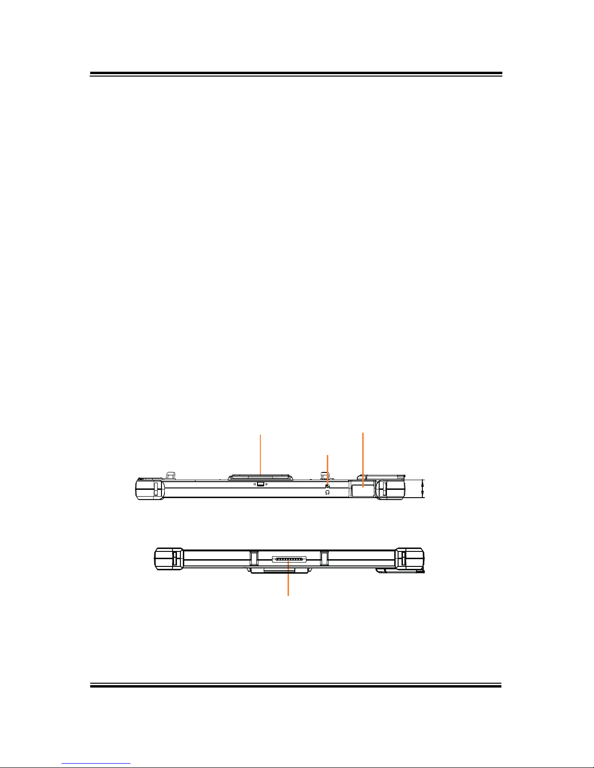
2.2.3 Side View
2.2.4 Top View
2.2.5 Bottom View
MH-5106 SERIES USER MANUAL
Page: 2-4
17.7
MSR Barcode Scanner
Earphone Jack
POGO Pins

Chapter 2 Getting Started
2.3 Lite Cradle System Overview
Unit: mm
2.3.1 Front View
2.3.2 Rear View
MH-5106 SERIES USER MANUAL
Page: 2-5
IN 12V
COM DWR
LAN
USB COM
Chapter 2 Getting Started
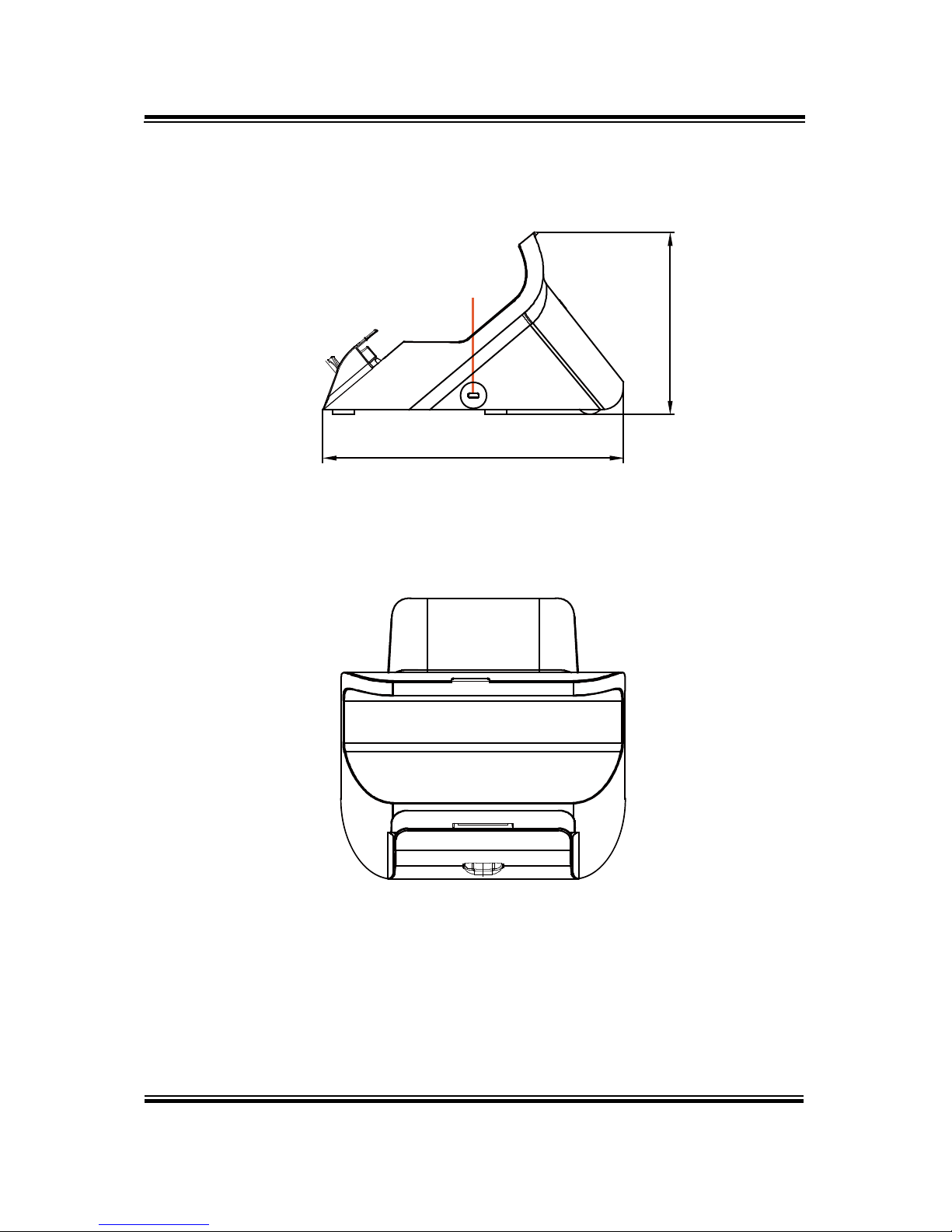
2.3.3 Side View
2.3.4 Top View
MH-5106 SERIES USER MANUAL
Page: 2-6
Kensington
Lock Slot
217.23
131.65

Chapter 2 Getting Started
2.3.5 Bottom View
MH-5106 SERIES USER MANUAL
Page: 2-7
LAN and Cash Drawer Selection
DWR LAN

Chapter 2 Getting Started
2.3.6 Quarter View
MH-5106 SERIES USER MANUAL
Page: 2-8
Chapter 2 Getting Started
2.4 Quick Setup
2.4.1 Turning the Power On from Pad and Connect to Wi-Fi
Long press the Power Button on the right side of the Pad to turn on the
system. Connect the Pad to a wireless network via Wi-Fi connection. (Refer to
the Side View section of Pad for the location of Power Button.)
How to Set Up Wi-Fi Connection
Step 1. From the bottom right corner of the screen, tap the ∧ icon from the
tool tray.
Step 2. From the small pop-up window , t ap on the Wi-Fi icon
if it shows
grey to activate Wi-Fi.
Step 3. Select a Wi-Fi network from the list and tap on it.
Step 4. Tap the Connect button.
Step 5. Enter the correct security key for the selected Wi-Fi network and wait
for the Wi-Fi connection to establish.
You can also swipe the screen f rom the right side of the Pad to bring up the
ACTION CENTER window and se lect Network menu item to ent er the Wi-Fi
network selection list.
For stability issue, always power off the Pad from W indows 10 OS. Make sure
you have closed a ll the applicatio n programs before you close W indows. Tap
on
Start icon from the bottom left corner of the Pad and select the
displayed
menu icon and select Shut down from the selection list to turn
off the Pad power.
MH-5106 SERIES USER MANUAL
Page: 2-9

Chapter 2 Getting Started
2.4.2 Turning the Power On and Connect to Local Network from
Lite Cradle
Prerequisite: Insert a ball point pen or a pin into the hole of DWR/LAN
selection switch slot located on the bottom base of the Lite Cradle, and switch
it to the LAN port location. See the pic tur e belo w:
Pres
s the Power Button on the right side of the Pad to turn on the system .
Connect the Ethernet cable to the LAN port on the rear side of the Lit e Cra dl e
and the other end of the ne twork cable to a p ort on your hub, s witc h or rout er.
(Refer to the Side View section of Pad for the location of Power Button.)
Refer to the I/O Ports Diagram section of Lite Cradle for the locatio n of LAN
port.
MH-5106 SERIES USER MANUAL
Page: 2-10
LAN and Cash Drawer Selection
DWR LAN

Chapter 2 Getting Started
2.4.3 Installing Battery for Pad
Make sure to power off the device first before you start installing the battery.
Step 1. Slide to unlock the left-side battery switch with your left hand. See
the Figure below.
Step 2. Use your left hand to push the right-side sliding tab to the right and
long press on it and hold it.
Step 3. Use a fingertip of your right hand to remove the battery from the slim
opening located under the Camera.
Step 4. Repl ac e a new battery onto the back of Pad and the right-side
locking switch snaps into place automatically.
Step 5. Slide the left-side battery switch to the right to secure and lock up the
replaced battery.
Note 1: The factory default battery cycle life guarantees to retain 80 percent of its original
capacity after the battery has been charged and discharged for 300 times.
Note 2: Batteries are consumerables and the limited warranty for MH-5106 battery is 1 year
only.
MH-5106 SERIES USER MANUAL
Page: 2-11
Step 1. Use your left hand to
slide to unlock left-side
battery switch.
Step 2. Push sliding tab to
the right side
and long press
on it and hold it.
Step 3. Use a fingertip of your right hand
to remove the battery from the slim
opening.
Step 4. Replace a new battery onto back
of Pad and the right-side locking
switch snaps into place
automatically.
Step 5. Slide the left-side
battery switch to the
right to secure and
lock up the replaced battery
to complete.

Chapter 2 Getting Started
Low Battery Indicator
The low battery indicator will show on the LCD screen when the battery is
nearly exhausted. When the low battery indicat or app e ars on the tool tray, you
should recharge the battery by connecting the power adapter of Pad/Lite
Cradle or replace a fully charged battery immediately.
2.4.4 Recharging Battery from Pad
Before you use MH-5106 Pad, follow the instructions below to charge the
battery:
Step 1. Connect the Pad’s AC power adapter to the DC-IN jack located on
the right side of the Pad. (Refer to the Side View section of Pad for
the location of the DC-IN Jack.)
Step 2. Plug the other end to an AC power outlet.
MH-5106 Pad battery will then start chargi ng, a nd t h e Po wer L ED ind ic ator on
the top left corner of the to uc h s c reen w ill the n f las h G REEN . After the batt ery
is fully charged, the Power LED indicator will turn to a solid green.
2.4.5 Recharging Battery from Lite Cradle
Step 1. Connect the Lite Cradle’s AC power adapter to the DC-IN power jack
located on the bottom of the Lite Cradle.
Step 2. Plug the other end to an AC power outlet.
The Power LED indicator on the to p left corner of the to uch screen will the n
flash GREEN. After the b attery is fully charged, the Power LED indicator will
turn to a solid green.
MH-5106 SERIES USER MANUAL
Page: 2-12

Chapter 2 Getting Started
2.4.6 Installing Integrated Pad Onto Lite Cradle
Step 1. From the bottom side of Pad, align the two locking tabs located
on both side of the POGO pins to their mating slots located inside
of Lite Cradle base respectively.
Step 2. Lock the two locking tabs of Pad into their mating slots inside the
Lite Cradle base and the Pad snaps into place.
Step 3. The installation is completed.
MH-5106 SERIES USER MANUAL
Page: 2-13

Chapter 2 Getting Started
2.4.7 Separating Integrated Pad From Lite Cradle
Step 1. Push down the Lock Switch on the front of Lite Cradle.
Step 2. Separate the integrated pad from the lite cradle. See the picture
below:
MH-5106 SERIES USER MANUAL
Page: 2-14
Push down the Lock Switch to eject.

Chapter 2 Getting Started
2.4.8 Scanning Barcodes and QR Codes
Step 1. Press to turn on the Scan Button located on the right/left side of the
Pad. (Refer to the Side View section for the location of the Scan
Button.)
Step 2. Point the Barcode Scanner at the barcode or QR code that you
want to scan and position the light beam on the barcode/QR code.
(Refer to the Top View section of Pad for the location of the Barcode
Scanner.)
After the barcode/QR code has been scanned successfully, you will hear one
beep sound.
MH-5106 SERIES USER MANUAL
Page: 2-15

Chapter 2 Getting Started
2.4.9 Installing Hand Strap
Step 1. Tighten the two screws of the strap bracket set onto the strap bracket
holes on the back cover.
Step 2. Ready to hold the hand strap attached on the strap brackets to lift up
the Pad with your hand.
Note: The strap bracket set is pre-ins
talled for easy user installation before
the shipment. The strap bracket set includes 2 x strap brackets, 2 x
pan head screws (M3 x 6 mm) and 1 x Velcro badge.
MH-5106 SERIES USER MANUAL
Page: 2-16

Chapter 2 Getting Started
2.4.10 Installing Neck Strap
Step 1. Insert one end of the provided neck strap through the upper opening
of the right-side bumper rubber and adjust to tighten the neck strap.
Step 2. Insert another end of the neck strap through the upper opening of the
left-side bumper rubber and adjust to tighten the neck strap.
Step 3. Put the installed neck strap around your neck to carry the Pad
around.
Note: You can also select to put the neck strap through the lower openings of
the right-side and left-side bumper rubbers.
MH-5106 SERIES USER MANUAL
Page: 2-17

Chapter 2 Getting Started
2.5 Pad Specifications
Fundamental Spec. (Conform to RoHS Directive)
Operator
Display (LCD)
Type
10.1” LCD
Resolution
WXGA 1280 x 800 dots
Brightness Typical 400 cd/m2
Life time of Backlight
Lamp
30,000 hours
Interface
LVDS
Backlight
Type
LED Backlight
Touch Panel
Type
10.1” PCT
Interface
I2C
CPU
BGA on board CPU
Actions S500 (ARM Cortex A9 R4 CPU)
Chipset
Intel Platform
Built-in CPU
Memory
DDR3L on Board
DDR3L 1GB / 2GB
PMIC or EC
Type
Actions A T C2603C
Interface I2C
Charger
Type
TI BQ24192
Interface
I2C
Storage (eMMC)
Type
16GB / 32GB / 64GB
Interface
SDIO
Storage (SD)
Type
MicroSD Slot
Interface
SDIO
Hardware
Monitor
Type
(1) Volt age detection (Battery)
(2) CPU & System Temperature detection
(3) CPU Temperature over heat warning
(4) CPU Temperature over heat shut down
Speaker
Type
1W Speaker x1
Wi-Fi +
B
luetooth
M
odule IC
Type
802.11 a/b/g/n wireless LAN and Bluetooth
4.0 module
Interface
Wi-Fi: SDIO / Bluetooth: UART
MH-5106 SERIES USER MANUAL
Page: 2-18

Chapter 2 Getting Started
G-Sensor
(
Accelerator
sensor)
Type
ST
Interface I2C
LED Indicator
Tri-color Light LED
Green / Yellow / Red
LED
1. Power LED (Green):
a. Start OSconstant Green light
b. Charging flashing Green l ight
c. Full chargeconstant Green light
2. Alarm LED (Yellow):
a. 4%< Battery Capacity <
8%flashing Yellow light
b. Battery Capacity < 4% system turns to
SleepYellow Alarm LED turns off.
3. Error LED (Red):
a. S0 unlock battery switchflashing
Red light
b. Battery errorflashing Red light
Power Supply
Type
DC 12V/2A/24W for USB / Cradle
Operating
System
OS Android 5.1.1 (Linux Kernel 3.10)
Dimension
L x W x T
259.9 x 175.9 x 17.7mm
Weight
Pad only
838g (without any optional devices attached)
Certificate
-
FCC/CE
Battery Pack
Operation time
Main battery(1S2P) 8 hours @ 7900mAh
Coin Battery
RTC Battery
160mAh
Battery Pack
Charging time
Main battery (1S2P) Power ON: 5 hours
Power OFF: 3.3 hours
IP Rating
Body unit
IP54 (front panel only)
Drop Impact
Resistance
- 1.2m
Temperature
Operating
Temperature
0°C ~ 40°C (32°F ~ 104°F)
Stor age Temperature
-20°C ~ 60°C (-4°F ~ 140°F)
Humidity
Operating Humidity
0~90%RH (no condensation)
Storage Humidity
0~95%RH (no condensation)
MH-5106 SERIES USER MANUAL
Page: 2-19

Chapter 2 Getting Started
Integrated Devices (Optional)
Barcode
S
canner
(Optional)
Type
Honeywell 2D Barcode scanner
Interface
UART
3G Module
(Reserved
)
Type
3.75G module IC supports SIM card interface
(on board)
Interface
USB
NFC Module
(Reserved
)
Type
NXP N-P300
Interface
I2C
Rear Camera
Type
5M pixels camera module with autofocus
function on the back cover
Interface
USB
MSR Module
Type
Meet ISO 7811, support AAMVA / JIS II format,
support single / dual / triple tracks
Interface
USB
Smart Card
Reader
Module
Type
USB port (meet ISO 7816 & EMV Level 1 & 2
Certification)
Interface
USB
External I/O Ports
DC-IN Jack
Type
DC-IN Jack x 1
Cradle
Connector
Type
POGO pins (1x10 pins) x 1
USB
Type Standard USB (Type A) x1 for external
expansion
SD (Secure
Digital)
Type
MicroSD Slot for internal memory expansion
SIM
Type
SIM Card Slot for cellular network services
Audio Jack
Type
Audio Jack (3.5 mm) x1
External Buttons (for side I/O & front panel)
Power Button
Type
Power Button x1
Scan Button
Type
2 x Scan buttons (left & right)
MH-5106 SERIES USER MANUAL
Page: 2-20

Chapter 2 Getting Started
2.6 Lite Cradle Specifications
Lite Cradle
Cradle
Connector
Type
POGO pins (1 x 10 pins) x 1
Interface
USB 2.0/Power/GND
DC-IN Jack
Type
DC 12V IN x 1
USB
Type
Standard USB 2.0 port (T ype A) x 2
COM
Type
R-J45 with 12V/5V/RI x 1
COM
Type
D-Sub 9 with 12V/5V/RI x 1
LAN
(
10/100 Mbps)
or
DWR
(Cash Drawer)
Type
RJ-45 x 1
Type
RJ-11 with 12V/1A x 1
DIP Switch
-
LAN Port and Cash Drawer selection
Kensington
Security
Lock Slot
Type 1
Lock Switch
-
Fixing between Integrated Pad and Crad le
AC Power
Adapter
Type 12V/5A/60W AC Power Adapter x 1
Dimension
L x W x T
220 x 217.23 x 131.65mm
Weight
Lite Cradle only
About 858g
Note: The functions of Ethernet LAN & Cash Drawer are co-layout and can be
selected by DIP Switch.
MH-5106 SERIES USER MANUAL
Page: 2-21
DC-IN RJ-45 Cash LAN
2 x
D-Sub 9
Drawer
USB 2.0
DIP
Switch

Chapter 2 Getting Started
2.7 OS Specifications
OS Description
Andro
id 5.1.1 Android 5.1.1 (Linux Kernel 3.10)
2.8 API Specification
•
Cash Drawer API
MH-5106 SERIES USER MANUAL
Page: 2-22

Chapter 2 Getting Started
2.9 Safety Precautions
Before operating this system, read the follo wing information carefully to protect your
systems from damages, and extend the life cycle of the system.
1. Check the Line Voltage
• The operating voltage for the power supply should be within the r ange of
100V to 240V AC; otherwise, the system may be damaged.
2. Environ mental Co nditio ns
• Place your MH-5106 on a sturdy, level surface. Be sure to allow enough
space around the system to have easy access needs.
• Avoid installing your MH-5106 system in extremely hot or cold places.
• Avoid direct sunlight exposure for a long period of time (for example, in a
closed car in summer time. Also avoid the system from any heating device.).
Or do not use MH-5106 when it has been left outdoor s in a cold winter day.
• Avoid moving the system rapidly from a hot place to a cold place, and vice
versa, because condensation may occur inside the system.
• Protect your MH-5106 from strong vibrations which may cause hard disk
failure.
• Do not place the system too close to any radio-active device. Radio-active
device may cause signal interference.
• Always shut down the operating system before you turn off the power.
3. Handling
• Avoid placing heavy objects on the top of the system.
• Do not allow any objects to fall into this device.
• If water or other liquid spills into the device, unplug the power cord
immediately.
4. Good Care
• When t he o ut sid e ca s e ge t s stained, re move t he sta i ns u si ng neut ra l was hi ng
agent with a dry cloth.
• Never use strong agents such as benzene and thinner to clean the surface of
the case.
• If heavy stains are present, moisten a cloth with diluted neutral washing
agent or al cohol and then wipe thoroughly with a dry cloth.
• If dust is accumulated on the case surface, remove it by using a special
vacuum cleaner for computers.
MH-5106 SERIES USER MANUAL
Page: 2-23

3 Hardware Configuration
This chapter contains helpful information about the jumper
& connector settings, and component locations.
The following sections are included:
• Pad Function Buttons and I/O Ports
• Lite Cradle I/O Ports Diagram
• Pad Main Board Component Locations
• Pad Mainboard Connectors Quick Reference Table
• Setting Pad Main Board Connectors
• Daughter Board MR-5100RA-5 and MR-5100RA-2
Connectors Quick Reference T able
• Setting Daughter Board MR-5100RA-5 Connectors
and Jumpers
• Setting Daughter Board MR-5100RA-2 Connectors
MH-5106 SERIES USER MANUAL
Page: 3-1

Chapter 3 Hardware Configuration
3.1 Pad Function Buttons and I/O Ports
3.1.1 Power Button
To turn on the system, press the Power Button on t he right side
of the Pad briefly.
ACTION
ASSIGNMENT
Press
0V
Release
+3.3V
3.1.2 DC-IN Port
Port Name: DC-IN
Description: DC Power-In Port. The DC-IN Port is located
on the right side of the Pad.
PIN
ASSIGNMENT
PIN
ASSIGNMENT
0
+12V
2
GND
1
+12V
3
GND
3.1.3 USB Port
Port Name: USB1
Description: USB Type A Port (Side I/O)
PIN
ASSIGNMENT
PIN
ASSIGNMENT
1
+5V (Max.
current: 0.5A)
3
D+
2
D- 4 GND
Note: The USB1 port is provided with Standby power 5V.
DC-IN
USB1
Power
Button
MH-5106 SERIES USER MANUAL
Page: 3-2

Chapter 3 Hardware Configuration
3.1.4 Audio Port
Port Name: AUDIO1
Description: Audio Port located on the top right side
of the Pad.
PIN
ASSIGNMENT
1
LEFT
2
RIGHT
3
GND
4
GND
5
HP_DET
3.2 Lite Cradle I/O Ports Diagram
3.2.1 I/O Ports Diagram
The I/O ports are located on the bottom side of the Lite Cradle.
AUDIO1
MH-5106 SERIES USER MANUAL
Page: 3-3
DC-IN RJ-45 Cash LAN
2 x
D-Sub 9
Drawer
USB 2.0
DIP
Switch
Chapter 3 Hardware Configuration
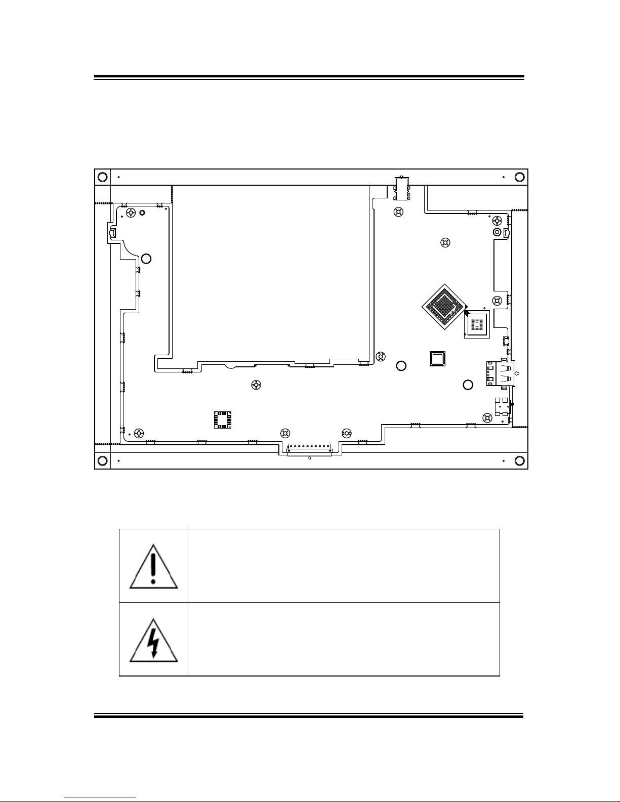
3.3 Pad Main Board Component Locations
3.3.1 Top View of Pad Main Board Component Locations
M/B: MB-5106
Figure 3-1. MB-5106 Main Board Component Locations (Top View)
WARNING: Always disconnect the power cord when you are
working with the connectors on the main board. Make sure
both the system and the external devices are turned OFF as
s
udden surge of power could ruin sensitive components.
Make sure MH-5106 is properly grounded.
CAUTION: Observe precautions while handling electrostatic
sensitive components. Make sure to ground yourself to
prevent static charge while configuring the con nec t ors. Use a
grounding wrist strap and place all electronic components in
any static-shielded devices.
MH-5106 SERIES USER MANUAL
Page: 3-4
5
3
1
2
4
AUDIO1
BUTTON2
BUTTON1
PWR_SW1
USB1
3 2
DC_IN1
0
1
16
CRADLE1
1
10
1 4
1 2
1 2
1
2

Chapter 3 Hardware Configuration
3.3.2 Bottom View of Pad Main Board Component Locations
Figure 3-2. MB-5106 Main Board Component Locations (Bottom View)
MH-5106 SERIES USER MANUAL
Page: 3-5
3
5
1
4
2
AUDIO1
BAT_LOCK1
JCCM1
12 1
JBARCODE1
1 5
JMSR1
JDEBUG1
JSPK1
1 2
RST1
JNFC1
5
JADFU1
RST_SW1
JSCR1
C1 C2 C3 C4
1
4
8 1
SIM1
BAT1
ECN:
JLVDS1
C5 C6 C7 C8
M/N:
SD1
2
1
JBAT1
1
8
JTOUCH1
1 6
J1
4
3
2
1
1
5
15
1

Chapter 3 Hardware Configuration
3.4 Pad Mainboard Connectors Quick Reference
Table
CONNECTOR Description
NAME
Touch Screen Connector
JTOUCH1
NFC Connector
JNFC1
LVDS Connector
JLVDS1
RTC Battery Connector
JBAT1
Earphone Jack Connector
AUDIO1
Speaker Connector
JSPK1
Barcode Scanner Connector
JBARCODE1
Left Scan Button
BUTTON1
Right Scan Button
BUTTON2
Power Button
PWR_SW1
Battery Connector
BAT1
DC IN Jack Connector
DC_IN1
Cradle Connector
CRADLE1
MCU F/W Update Connector
J1
Battery Lock Switch Button
BAT_LOCK1
MicroSD Card Connector
SD1
CCD Front Camera Connector
JCCM1
Universal Serial Bus 2.0 Connector
USB1
MSR Connector
JMSR1
SCR Connector
JSCR1
SIM Card Connector
SIM1
Reset Button
RST_SW1
ADFU Button
RST1
Debug Connector
JDEBUG1
ADFU Connector
JADFU1
MH-5106 SERIES USER MANUAL
Page: 3-6

Chapter 3 Hardware Configuration
3.5 Setting Pad Main Board Connectors
3.5.1 Touch Panel Connector (JTOUCH1)
Connector Location: JTOUCH1 (rear side of mainboard)
Description: Touch Panel Connector
PIN
ASSIGNMENT
1
V3P3S_TCH
2
GND
3
GND
4
I2C2_Touch_SCL
5
I2C2_Touch_SDA
6
GND
7
TOUCH_INT_R
8
TOUCH_RST_R
3.5.2 NFC Connector (JNFC1)
Connector Location: JNFC1 (rear side of mainboard)
Description: NFC (Near Field Communication) Connector
PIN
ASSIGNMENT
15
GND
14
VDD_IO
13
VBAT
12
SWP_PWR
11
DWL_REQ
10
WakeUp
9
GND
8
I2C_SCL
7
I2C_SDA
6
VDD_SIM
5
IRQ
4
VCC_BOOST
3
NC
2
GND
1
VBAT
JNFC1
JTOUCH1
MH-5106 SERIES USER MANUAL
Page: 3-7

Chapter 3 Hardware Configuration
3.5.3 LVDS Connector (JLVDS1)
Connector Location: JLVDS1 (rear side of mainboard)
Description: LVDS (Low-Voltage Differential Signaling) Connector
PIN
ASSIGNMENT
1
NC
2
VDD
3
VDD
4
NC
5
NC
6
NC
7
NC
8
LVDS_A_N0
9
LVDS_A_P0
10
GND
11
LVDS_A_N1
12
LVDS_A_P1
13
GND
14
LVDS_A_N2
15
LVDS_A_P2
16
GND
17
LVDS_A_CLK_N
18
LVDS_A_CLK_P
19
GND
20
LVDS_A_N3
21
LVDS_A_P3
22
GND
23
NC
24
NC
25
GND
26
NC
27
SEL
28
GND
29
NC
JLVDS1
MH-5106 SERIES USER MANUAL
Page: 3-8

Chapter 3 Hardware Configuration
PIN
ASSIGNMENT
30
NC
31
GND
32
GND
33
GND
34
NC
35
LVDS_BKLT_CTRL
36
NC
37
NC
38
VLED
39
VLED
40
VLED
3.5.4 RTC Battery Connector (JBAT1)
Connector Location: JB AT 1 (rear side of mainboard)
Description: RTC (Real-Time Clock) Battery Connector
The RTC battery provides power supply for the internal
real-time clock and calendar.
PIN
ASSIGNMENT
2
GND
1
VCC
3.5.5 Battery Connector (BAT1)
Connector Location: BAT 1 (rear side of mainboard)
Description: Battery Connector
PIN
ASSIGNMENT
1
BT+
2
BT+
3
BAT1_SENSE
4
BAT _DET
5
GND
6
BAT _SCL
7
BAT _SDA
8
GND
JBAT1
BAT1
MH-5106 SERIES USER MANUAL
Page: 3-9

Chapter 3 Hardware Configuration
3.5.6 Earphone Jack Connector (AUDIO1)
Connector Location: AUDIO1 (top side of mainboard)
Description: Earphone Jack Connector
PIN
ASSIGNMENT
PIN
ASSIGNMENT
5
HP_DET
3
GND
2
RIGHT
1
LEFT
- - 4
GND
AUDIO1
MH-5106 SERIES USER MANUAL
Page: 3-10

Chapter 3 Hardware Configuration
3.5.7 Speaker Connector (JSPK1)
Connector Location: JSPK1 (rear side of mainboard)
Description: Speaker Connector
PIN
ASSIGNMENT
PIN
ASSIGNMENT
1
SPK-
2
SPK+
3.5.8 Barcode Scanner Connector (JBARCODE1)
Connector Location: JBARCODE1 (rear side of mainboard)
Description: Barcode Scanner Connector
PIN
ASSIGNMENT
1
NC
2
VCC3_3
3
GND
4
RXD
5
TXD
6
NC
7
NC
8
NC
9
Buzzer
10
NC
11
Wake up
12
Trigger
JSPK1
JBARCODE1
MH-5106 SERIES USER MANUAL
Page: 3-11

Chapter 3 Hardware Configuration
3.5.9 Left Scan Button (BUTTON1)
Connector Location: BUTTON1 (top side of mainboard)
Description: Left Scan Button
PIN
ASSIGNMENT
1
GND
2
SCAN_EN_SW
3.5.10 Right Scan Button (BUTTON2)
Connector Location: BUTTON2 (top side of mainboard)
Description: Right Scan Button
PIN
ASSIGNMENT
1
GND
2
SCAN_EN_SW
BUTTON1
BUTTON2
MH-5106 SERIES USER MANUAL
Page: 3-12

Chapter 3 Hardware Configuration
3.5.11 Power Button (PWR_SW1)
Connector Location: PWR_SW1 (top side of mainboard)
Description: Power Button
ACTION
ASSIGNMENT
Press
0V
Release
3.3V
3.5.12 DC IN Jack Connector (DC_IN1)
Connector Location: DC_IN1 (top side of mainboard)
Description: DC IN Jack Connector
PIN
ASSIGNMENT
PIN
ASSIGNMENT
3
GND
2
GND
0
+12V
1
+12V
DC_IN1
PWR_SW1
MH-5106 SERIES USER MANUAL
Page: 3-13

Chapter 3 Hardware Configuration
3.5.13 Cradle Connector (CRADLE1)
Connector Location: CRADLE1 (rear side of mainboard)
Description: Cradle Connector
PIN
ASSIGNMENT
1
GND
2
+12V
3
+12V
4
GND
5
USB_DP
6
USB_DP
7
USB_DN
8
USB_DN
9
+5V
10
GND
3.5.14 MCU F/W Update Connector (J1)
Connector Location: J1 (rear side of mainboard)
Description: MCU Firmware Update Connector
PIN
ASSIGNMENT
1
MCU_MISO
2
3.3V
3
MCU_SCK
4
MCU_MOSI
5
MCU_RST
6
GND
CRADLE1
J1
MH-5106 SERIES USER MANUAL
Page: 3-14

Chapter 3 Hardware Configuration
3.5.15 Battery Lock Switch Button (BAT_LOCK1)
Connector Location: BAT _ L OCK1 (rear side of mainboard)
Description: Battery Lock Switch Button
PIN
ASSIGNMENT
PIN
ASSIGNMENT
3
NC
1
GND
4
NC
2
BAT _LOCK
3.5.16 MicroSD Card Connector (SD1)
Connector Location: SD1 (rear side of mainboard)
Description: MicroSD (Secure Digital) Card Connector
PIN
ASSIGNMENT
1
DAT 2
2
CD/DAT3
3
CMD
4
VDD
5
CLK
6
GND
7
DATA0
8
DAT 1
9
CARD DETECT
10
GND
BAT_LOCK1
SD1
MH-5106 SERIES USER MANUAL
Page: 3-15

Chapter 3 Hardware Configuration
3.5.17 CCD Front Camera Connector (JCCM1)
Connector Location: JCCM1 (rear side of mainboard)
Description: CCD (Charge-coupled Device) Front
Camera Connector
PIN
ASSIGNMENT
5
GND
4
GND
3
D+ 2 D- 1 5V
3.5.18 USB 2.0 Connector (USB1)
Connector Location: USB1 (right side of mainboard)
Description: USB 2.0 Connector
PIN
ASSIGNMENT
4
GND
3
D+ 2 D- 1 +5V
JCCM1
USB1
MH-5106 SERIES USER MANUAL
Page: 3-16

Chapter 3 Hardware Configuration
3.5.19 MSR Connector (JMSR1)
Connector Location: JMSR1 (rear side of mainboard)
Description: MSR (Magnetic-Stripe Card Reader)
Connector
PIN
ASSIGNMENT
1
5V 2 D- 3 D+ 4 GND
5
GND
3.5.20 SCR Connector (JSCR1)
Connector Location: JSCR1 (rear side of mainboard)
Description: SCR Connector
PIN
ASSIGNMENT
1
5V 2 D- 3 D+ 4 GND
JMSR1
JSCR1
MH-5106 SERIES USER MANUAL
Page: 3-17

Chapter 3 Hardware Configuration
3.5.21 SIM Card Connector (SIM1)
Connector Location: SIM1 (rear side of mainboard)
Description: SIM (Subscriber Identity Module) Card
Connector
PIN
ASSIGNMENT
PIN
ASSIGNMENT
C5
GND
C1
VSIM
C6
VPP
C2
RST
C7
DATA
C3
CLK
C8
RSV
C4
RSV
3.5.22 Reset Button (RST_SW1)
Connector Location: RST_SW1 (rear side of mainboard)
Description: Reset Button
ACTION
ASSIGNMENT
Press
1.8V
Release
Floating
SIM1
RST_SW1
MH-5106 SERIES USER MANUAL
Page: 3-18

Chapter 3 Hardware Configuration
3.5.23 ADFU Button (RST1)
Connector Location: RST1 (rear side of mainboard)
Description: ADFU Button
ACTION
ASSIGNMENT
Press
0V
Release
3.1V
3.5.24 Debug Connector (JDEBUG1)
Connector Location: JDEBUG1 (rear side of mainboard)
Description: Debug Connector
PIN
ASSIGNMENT
5
GND
4
GND
3
RXD
2
TXD
1
3.3V
3.5.25 ADFU Connector (JADFU1)
Connector Location: JADFU1 (rear side of mainboard)
Description: ADFU Connector
PIN
ASSIGNMENT
5
GND
4
GND
3
D+ 2 D- 1 5V
RST1
JDEBUG1
JADFU1
MH-5106 SERIES USER MANUAL
Page: 3-19

Chapter 3 Hardware Configuration
3.6 Daughter Board MR-5100RA-5 and
MR-5100RA-2 Connectors Quick Reference
Table
JUMPER Description
NAME
COM1 Port Pin9 Definition Selectio n
Guide (MR-5100RA-5)
JP_COM1
COM2 Port Pin9 Definition Selection
Guide (MR-5100RA-5)
JP_COM2
CONNECTOR Description
NAME
COM Port Connector (RJ45)
COM1
COM Port Connector (D-Sub 9)
COM2
Universal Serial Bus 2.0 Connector
(Dual Laye rs)
USB1
Cash Drawer Connector
DRW1
Local Area Network Connector
LAN1
DC IN Jack Connector
DC_IN1
LAN & Cash Drawer Function
Switch (MR-5100RA-5 Bottom Side)
SW1
Lite Cradle Connector
(MR-5100RA-2)
CRADLE1
MH-5106 SERIES USER MANUAL
Page: 3-20

Chapter 3 Hardware Configuration
3.6.1 Jumper Settings of Daughter Board MR-5100RA-5
Note: W hen the Lite Cradle is joined with Integrated Pad, the COM2 and COM3 ports
shown on Pad system are actually COM1 and COM2 ports of the daughter
board respectively, because the Lite Cradle’s COM ports are deployed
according to OS Image built by Protech and COM1 port placement has been
used by Pad system.
MH-5106 SERIES USER MANUAL
Page: 3-21

Chapter 3 Hardware Configuration
Figure 3-3. MR-5100RA-5 Daughter Board Component Locations (Bottom View)
3.6.2 Daughter Board MR-5100RA-2 Connectors Location
Figure 3-4. MR-5100RA-2 Daughter Board Component Locations (Top View)
Figure 3-5. MR-5100RA-2 Daughter Board Component Locations (Bottom View)
MH-5106 SERIES USER MANUAL
Page: 3-22
10 6
5 1
LAN
DWR
1
4
1
3
SW1
1
M/N:
ECN:
S/N:
1
5
1
5
2
6
2
6
9
1
8 5
10
2
4
1
1
9
2 10
14 12
13
11
ON
1
CRADLE1
JP1
D2
9
1
Pb-free

Chapter 3 Hardware Configuration
3.7 Setting Daughter Board MR-5100RA-5
Connectors and Jumpers
3.7.1 COM1, COM2 Port Pin9 Definition Selection Guide
(
JP_COM1 and JP_COM2)
Jumper Location: JP_COM1 and JP_COM2
Description: COM1, COM2 Port Pin9 RI/+5V/+12V Selection
SELECTION JUMPER SETTING JUMPER IL LU STRATION
RI
1-2
(Default Setting)
JP_COM1 JP_COM2
12V 3-4
JP_COM1 JP_COM2
5V 5-6
JP_COM1 JP_COM2
MH-5106 SERIES USER MANUAL
Page: 3-23

Chapter 3 Hardware Configuration
3.7.2 RJ-45 COM Port (COM1)
COM1(RS-232, RJ-45) C onnector Pin Assignment
PIN
ASSIGNMENT
PIN
ASSIGNMENT
1
DCD
6
DSR
2
RXD
7
RTS
3
TXD
8
CTS
4
DTR
9
RI/5V/12V
5
GND
-
Note: COM1 Pin 9 is selectable for RI, +5V or +12V by jumper setting. Default setting is RI.
Please see “COM1, COM2 Port Pin9 Definition Selection Guide” section for
selection details.
3.7.3 D-Sub 9 COM Port (COM2)
COM2(RS-232, D-Sub 9 ) Connector Pin Assignment:
PIN
ASSIGNMENT
PIN
ASSIGNMENT
1
DCD
6
DSR
2
RXD
7
RTS
3
TXD
8
CTS
4
DTR
9
RI/5V/12V
5
GND
-
Note: COM2 Pin 9 is selectable for RI, +5V or +12V by jumper setting. Default setting is RI.
Please see “COM1, COM2 Port Pin9 Definition Selection Guide” section for
selection details.
5
1
9
6
COM2
101
COM1
MH-5106 SERIES USER MANUAL
Page: 3-24

Chapter 3 Hardware Configuration
3.7.4 DC-IN Port (DC_IN1)
Port Name: DC_IN1
Description: DC Power-In Port. The DC-IN Port is located
on the bottom side of Lite Cradle.
PIN
ASSIGNMENT
1
VCC12V
2
GND
3
GND
3.7.5
Dual USB Ports (USB1)
Port Name: USB1
Description: Dual USB 2.0 Type A Connectors
PIN
ASSIGNMENT
PIN
ASSIGNMENT
1
VCC5V
5
VCC5V
2
USB_DN
6
USB_DN
3
USB_DP
7
USB_DP
4
GND
8
GND
Note: The top USB 2.0 connector pin assignments are the
same as the one below.
USB1
DC_IN1
MH-5106 SERIES USER MANUAL
Page: 3-25

Chapter 3 Hardware Configuration
3.7.6 Local Area Network (LAN) Port (LAN1)
Port Name: LAN1
Description: a Giga LAN RJ-45 Port
PIN
ASSIGNMENT
1
MX0+
2
MX0-
3
MX1+
4
MX1-
5
CT1
6
CT2
7
NC
8
NC
9
NC
10
NC
11
SPEED_LED
12
VCC3.3V
13
LINK_ACT_LED
14
VCC3.3V
LAN LED Status
There are 2 LAN LED indicators for LAN on the bottom side of the Lite Cradle. By
observing their status, you can know the status of the Ethernet connection.
LAN LED
Indicator
Color Status Description
Left Sid e
LED
Orange Blink Giga LAN connection is activated.
Green Blink
10/100Mbps LAN connection is
activated.
Right Side
LED
Green On LAN switch/hub c onnected.
1
8
Green/Orange
Yellow
LAN1
MH-5106 SERIES USER MANUAL
Page: 3-26

Chapter 3 Hardware Configuration
3.7.7 Cash Drawer Port (DRW1)
Port Name: DRW1
Description: RJ-11 Cash Drawer Port
PIN
ASSIGNMENT
1
GND
2
DRAWER_OPEN
3
DRAWER_SENSE
4
VCC12V
5
NC
6
GND
3.7.8 LAN & Cash Drawer Function Switch (SW1)
Connector Name: SW1
Description: LAN Port and Cash Drawer function selection
PIN
ASSIGNMENT
1
CASH DRAWER
2
LAN
Note: Users need to use a ball point pen or a pin to toggle the DIP switch.
Default: LAN
16
DRW1
MH-5106 SERIES USER MANUAL
Page: 3-27
SW1

Chapter 3 Hardware Configuration
3.8 Setting Daughter Board MR-5100RA-2
Connectors
3.8.1 Lite Cradle Connector (CRADLE1)
Connector Name: CRADLE1
Description: Lite Cradle Connector
PIN
ASSIGNMENT
1
GND
2
CRA_DCIN
3
CRA_DCIN
4
GND
5
USB_DP
6
USB_DP
7
USB_DN
8
USB_DN
9
V5P0S
10
GND
CRADLE1
MH-5106 SERIES USER MANUAL
Page: 3-28

Appendix A System Diagrams
This appendix contains exploded diagrams and part
numbers of the Pad and Lite Cradle for MH-5106 system.
The following topics are included:
Exploded Diagrams for Integrated Pad
• Exploded Diagram for Top Cover, Touch Panel and
Panel Assembly
• Exploded Diagram for Pad PCBA Assembly
• Exploded Diagram for Bottom Cover Assembly
• Exploded Diagram for Camera Module, Barcode
Scanner Module and NFC Module Assembly
• Exploded Diagram for Back Cover Assembly
• Exploded Diagram for Smart Card Reader Assembly
Exploded Diagrams for Lite Cradle
• Exploded Diagram for Cradle Top Cover Assembly
• Exploded Diagram for Cradle PCBA & Bottom Cover
Assembly
MH-5106 SERIES USER MANUAL
Page: A-1

Appendix A System Diagrams
Integrated Pad Exploded Diagrams
Exploded Diagram For Top Cover & Touch Panel & Panel Assembly
ITEM
Description
Part No.
Q’ty
1
Touch Panel
52-380-14164023
1
2
Panel
52-351-12101028
1 3 MH-5100 Top Cover
30-002-12210378
1
4
MH-5100 Bumper Right
30-013-48300378
1 5 MH-5100 Bumper Left
30-013-48200378
1
6
MH-5100 Barcode Button
30-046-28110378
2 7 MH-5100 Power Button
30-046-28210378
1
8
MH-5100 Barcode Lens
30-021-10130378
1
MH-5106 SERIES USER MANUAL
Page: A-2
1
2
6
5
6
8
4
7
3

Appendix A System Diagrams
Exploded Diagram For Pad PCBA Assembly
ITEM
Description
Part No.
Q’ty
1
MH-5100 Panel Holder
20-029-34001378
1
2
Round Head With Spring Washer Screw
(M2.5x0.45Px6mm)
22-235-25006011 7
3
MH-5106 PCBA
MB-5106RA-x1N
1
4
Round Head With Spring Washer Screw
(M2x0.4Px5mm)
22-232-20005311 11
5
Sub-Battery
27-061-37801071
1
6
Thermal Pad 20x15mm
81-006-82015001
3 7 Thermal Pad 15x15mm
81-006-81515005
1
8
Thermal Pad 10x10mm
81-006-81010003
1
MH-5106 SERIES USER MANUAL
Page: A-3
2
3
5
4
1
8
6
7

Appendix A System Diagrams
Exploded Diagram For Bottom Cover Assembly
ITEM
Description
Part No.
Q’ty
1
MH-5100 Bottom Cover
30-002-12110378
1 2 MH-5100 Slide Key
30-002-28410378
2
3
MH-5100 Battery Hook
90-019-04110378
1 4 MH-5100 Battery Hook (Lock)
90-019-04210378
1
5
MH-5100 Battery Lock Spring
23-002-00000332
1 6 Round Washer Head Screw #1/T2.0x5mm
22-132-20005011
2
7
MH-5100 MSR-Bumper-Rubber
30-013-48100378
1 8 MSR Module
N/A
1
9
PA-8225 MSR Plate Pin (IDTECH)
20-005-07001342
2
10
Flat Head Screw #1 (T2.6x6mm)
22-112-26006011
2
11
Camera Lens
30-021-10330378
1
12
Warning Label
94-017-01601378
1
13
Rating Label
94-017-01602378
1
14
Speaker
27-021-37802071
1
MH-5106 SERIES USER MANUAL
Page: A-4
7
2
2
12
11
3
6
5
10
13
14
1
8
9
10
4
6

Appendix A System Diagrams
Exploded Diagram For Camera Module, Barcode Scanner Module and
NFC Module Assembly
ITEM
Description
Part No.
Q’ty
1
Camera PCBA
52-151-08040533
1
2
Round Head Screw
φ3.3/#1/M2x0.4Px4mm
22-232-20004811 2
3
Barcode Module
52-820-36800111
1
4
MH-5100 Barcode Fix Plate
80-005-03001378
1 5 Fillister Head Screw T1.7xL4mm
22-175-17004011
2
6
Round Head With Spring Washer Screw
(M2x0.4px5mm)
22-232-20005311 2
7
WIFI Antenna
27-029-37805071
1
8
Fillister Head Screw M2x0.4Px2.5mm
22-272-20004011
2 9 Bluetooth Antenna
27-029-37802071
1
10
3G Antenna
27-029-37803071
1
11
NFC Module
52-151-08030035
1
12
MH-5100 NFC Antenna
52-810-00140011
1
MH-5106 SERIES USER MANUAL
Page: A-5
1
2
9
3
6
5
4
8
7
11
10
12

Appendix A System Diagrams
Exploded Diagram For Back Cover Assembly
ITEM
Description
Part No.
Q’ty
1
MH-5100 Decoration Cover
30-002-28110378
1
2
Round Head With Spring Washer Screw
(M2.5x0.45Px6mm)
22-235-25006011 11
3
MH-5100 –Screw-Hole-Plug
30-013-06100378
9
4
MH-5100 Strap Bracket
80-006-06001378
2
5
Pan Head Screw M3x0.5Px6mm
22-220-30006011
2 6 M2xL3mm Flat-Head-Screw
22-215-20003011
4
MH-5106 SERIES USER MANUAL
Page: A-6
1
2
3
6
4
5

Appendix A System Diagrams
Exploded Diagram For Smart Card Reader Assembly
ITEM
Description
Part No.
Q’ty
1
MH-5100 Smart Card Cover
30-002-28610378
1
2
Round Head Screw φ3.3 / #1 /
M2x0.4Px4mm
22-232-20004811 2
3
Smart Card Module
52-551-16000010
1 4 Pan Head Screw (T2.0x4mm)
22-125-20004011
4
MH-5106 SERIES USER MANUAL
Page: A-7
2
2
1
3
4

Appendix A System Diagrams
Lite Cradle Exploded Diagrams
Exploded Diagram For Cradle Top Cover Assembly
MH-5106 SERIES USER MANUAL
Page: A-8

Appendix A System Diagrams
ITEM
Description
Part No.
Q’ty
1
MH-5100-Lite-Cradle-To p -Cover
30-002-28310378
1
2
MH-5100-Lite-Cradle-Rear-Cover
30-002-28210378
1 3 T2.6xL8mm Pan-Head-Screw
22-135-26008011
14
4
POGO Pin PCBA
10-625-01010025
1 5 MH-5100-Lite-Cradle-Hole-Cover
30-002-28510378
1
6
Pan Head screw (T2.0x4mm)
22-125-20004011
2 7 MH-5100-Lite-Cradle-Ejection-Spring
23-000-00010622
1
8
MH-5100-Lite-Cradle-Lock-Button
30-046-09230378
1
9
MH-5100-Lite-Cradle-Button-Hook
30-046-09130378
1
10
MT-590X Battery Lock Spring
23-000-01000132
2
11
MH-5100-Lite-Cradle-Lock-Spring-Cover
80-004-03001378
1
12
MH-5100-Lite-Cradle-Rotate-Plate
80-005-03002378
2
13
T2.3xL5mm Pan-Head-Screw
22-135-23005011
4
MH-5106 SERIES USER MANUAL
Page: A-9

Appendix A System Diagrams
Exploded Diagram For Cradle PCBA & Bottom Cover Assembly
ITEM
Description
Part No.
Q’ty
1
MH-5100-Lite-Cradle-Metal-Plate
80-005-03003378
1
2
Lite Cradle PCBA
N/A
1
3
Round Washer Head Screw
(M3x0.5Px6mm)
22-232-30006311 4
4
T2.6xL8mm Flat-Head-Screw
22-115-26008011
5 5 Rubber Foot φ=16x3.5mm (Black)
30-004-06800000
4
MH-5106 SERIES USER MANUAL
Page: A-10
 Loading...