

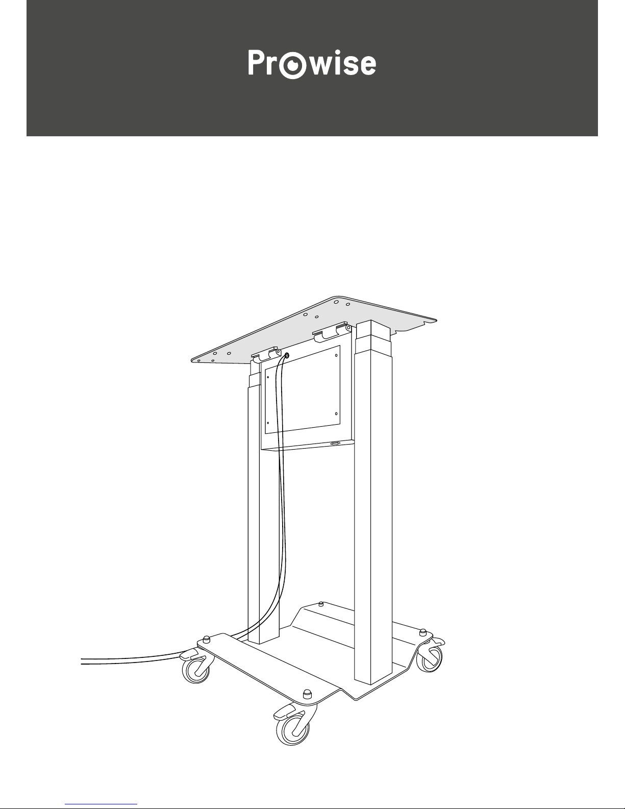
Assembly Manual
Prowise All-in-One Lift

Included
Please only use supplied parts
2 x
2 x
A • Basebox with 2 height adjustable
pillars
• 2 x locking screws
• 2 x hinge pins
• 1 x elevator control
• 1 x plug for screen
• 1 x plug for power cord
C • VESA bracket
• 1 x nut M8
• 1xatheadscrew
B • Chassis assembled with 4 wheels
• 8 x M6x20 bolts for assembling
the 2 adjustable pillars
8 x
1 x
1 x
2

See back side for required tools
Included with touchscreen
Please only use supplied parts
A • 55” or 65” Multi-touchscreen
• 4 x sheet-metal ring M8
• 4 x bolts M8x20
3
4 x
4 x

Put the basebox upright and connect it to the
net with the power cord. Place the actuator in
the highest position by using the lift control.
1
2
Assembly instructions
Put the chassis and basebox upside down.
Assemble the adjustable pillars to the chassis
(4 M6x20 bolts per pillar).
4 x M6x204 x M6x20
4 mm
Push the hinge pins, from the outsides, partially
in the hinges. Please note: the serrated edge of
the pins must be on the outside. Subsequently,
place the VESA bracket into the hinges.
3
3 mm
Push the hinge pins carefully through, then
completely hammer them by using a pin punch.
4
1 x pin 1 x pin
4

Screw 2 bolts partially into
the upper holes of the
screen, leave about 5 mm
between the head and
screen.
1 2 3 4
Place the screen in the
predrilled holes of the
VESA bracket. Completely
screw the bolts with an
Allen wrench.
Secure the two
remaining bolts
at the bottom
side, using an
Allen wrench.
Mount the elevator
control at the back
of the screen, in a
place of your own
choice.
7
See back side for required tools
6
M13
10
mm
Securetheactuatorwithaatheadscrewand
the nut (M8). Make use of a screwdriver
(10 mm) and a ring spanner (M13).
5
3 mm
Secure the hinge with a locking screw. Make use
of an Allen wrench (3 mm). Repeat this for the
other hinge.
1 x locking screw
2 x bolt M8x20
2 x bolt M8x20
1 x at head screw
1 x nut (M8)
5
With a 55” touchscreen: please operate the
following intermediate steps. After step 2,
unscrew the upper bolts one at a time. Apply the
rings and screw the bolts back in their position.
Repeat this action for the bottom side.

Prowise B.V.
Luchthavenweg 1b
6021 PX Budel
The Netherlands
Tel. +31 495 49 71 10
info@prowise.com
www.prowise.com
© Prowise 2015
Required tools
• Hammer
• Screwdriver 10 mm
• Pin punch 8 mm
• Allen wrench 3 + 4 + 6 mm
• Ring spanner M13
3 + 4 + 6 M13
10 mm 8 mm
 Loading...