

Pro-Weld CD-312 User Manual
OPERATION/MAINTENANCE
MANUAL


PRO WELD
CD-312
1.0
2.0
3.0
4.0
5.0
6.0
7.0
8.0
9.0
TABLE OF CONTENTS
INTRODUCTION
WARRANTY
UNPACKING YOUR UNIT
SUGGESTED SAFETY PRECAUTIONS
GENERA
THE CD WELDING PROCESS
POWER REQUIREMENTS
SYSTEM SPECIFICATIONS
WELDING SYSTEM HOOK-UP
9.1
9.2
9.3
L DESCRIPTION
Straight Polarity
Reverse Polarity
Cuphead Pin
1
1
1
1
2
2
3
3
4
4
5
6
10.0
11.0
11.5
12.0
13.0
14.0
15.0
16.0
17.0
SYSTEM OPERATION
GUN SET-UP
11.1
11.2
11.3
11.4
11.6
WELDABLE MATERIAL COMBINATIONS 15
CAUSES OF
TROUBLE SHOOTING POOR WELDS 16
ROUTINE WELDER MAINTENANCE 17
ASSEMBLY –CD-312 CONTROLLER
16.1
TROUBLE SHOOTING – ELECTRICAL 22
9
Standard
Installing or Changing Collets or Chucks 10
For Weld Pins with Collet Protector 10
Template Adapter
Collet Protector with Blunt Leg 11
Parts List LD CD Handgun 14
PC Board Assembly Drawing
POOR OR ERRATIC WELDS 16
11
21
7
9
18,19,20
18.0
19.0
CHECK LIST CD-312 SYSTEM P.N. 100-0108 24
CHECK LIST CD-312 SYSTEM P.N. 100-0109 24

PRO WELD
CD-312
LIST OF FIGURES
1
2 STRAIGHT POLARITY HOOK-UP 4
3
4
5
6 STANDARD GUN SETUP 9
7
8 TEMPLATE ADAPTER GUN SETUP 11
9 COLLET PROTECTOR/
10
CD CONTACT PROCESS
REVERSE POLARITY HOOK-UP
CUPHEAD PIN HOOK-UP
FRONT PANEL LAYOUT
COLLET PROTECTOR SETUP
LIGHT DUTY CD GUN
2
6
7
10
BLUNT LEG SETUP
13
5
11
11
12
13
14
15 G
16
17
18
19
HOT WELD
COLD WELD
ARC BLOW
WELD WITHOUT FOOTPIECE
PARTS LIST
PARTS LIST
PARTS LIST
PC BOARD
16
17
OOD WELD
21
16
17
17
18
(continued)
(continued)
19
20
PRO WELD
CD-312

PRO WELD
CD-312
PRO WELD
CD-312

PRO WELD
CD-312

PRO WELD
1
.0 INTRODUCTION
Your new stud welding equipment is carefully
constructed of the finest components and materials
available. Used
you years of profitable, efficient service.
The system incorporates the latest in enginee
ing advances, for completely reliable end welding of
mild steel, stainless steel, aluminum and lead free
copper and brass fasten
A careful study of this manual will enable you
to understand how the welder operates to insure
proper performance under al
properly, this equipment will give
2.0 WARRANTY
The electrical and mechanical components of
the stud welder are thoroughly performance i
spected prior to assembly in the welder. The asse
bled welder is completely performance checked. The
welder is delivered to you in functional electro
mechanical condition.
All p
arts used in the assembly of the welder
and its accessories are fully warranted for a period of
1 YEAR from the date of delivery
welding capacitors are warranted for a period of 1
YEAR from the date of delivery. The printed circuit
boards
for a period of 3 years.
the right to repair or replace, at their option, defe
tive parts which fail during the guarantee period.
No
ment
purchaser within ten (10) days after the defect is first
discovered. The manufacturer does not assume any
liability for paying shipping cost or any labor or m
terials furnished where such cost are not expressly
authorized in writing.
acces
abuse, improper installation, maladjustment, or use
not in accordance with the operating instructions fu
nished by the manufacturer. The warranty is valid
only when studs are purchased from sources a
proved by the manufacturer or are of identical spec
fi
used in all proweld equipment are warranted
Under the warranty, the manufacturer reserves
tice of any claim for warranty repair or replac
must be furnished to the manufacturer by the
The manufacturer does not warrant any parts or
sories against failures resulting from misuse,
cations to the manufacturer’s
ers.
l operating conditions.
. In addition, the
n-
m-
-
c-
e-
a-
p-
CD-312
3
.0 UNPACKING YOUR UNIT
possible to the point of installation before unpacking
it. Do not operate the unit from an extension power
r-
cord if possible. Once the unit is unpacked it is reco
mended that you inspect it for any physical damage.
inspected at the factory. Upon
hooked up to the recommended incoming power b
fore welding. We recommend that you check that you
have received all the items listed on the shipping
check list. (see SECTION 1
adequate ventilation. Do not restrict the air flow
through the side l
the control housing.
Upon receipt of your unit, place it as close as
Your unit has been completely assembled and
receipt, the unit must be
8 or 19)
Place the unit in a large enough area to provide
ouvers. Do not allow water to enter
4.0 SUGGESTED SAFETY PRECA
TIONS
ity of the welder to observe certain safety rules to i
sure his personal safety and to protect those working
near him.
Reference is directed, without endorsement or
recommendation, t
and Cutting, and to AWG Publication A6,1-66, Re
om
ing.
r-
i-
while welding or weld in the rain. Avoid wear-
In any welding operation, it is the responsibi
o ANSI Z49.1, Safety in Welding
mended Safety Practices for Gas-Shield Arc Wel
1. Always treat electricity with respect. Under
open circuit conditions, the welding machine
output voltage may be dang
2. Don’t work on live circuits or conductors.
Disconnect the main power line before check
ing the machine or perform
nance operations.
3. Be sure the welding machine cabinet is
properly grounded to a good electrical ground.
4. Don’t stand in water or on a damp floor
ing wet sweaty cloths when welding.
U-
erous.
ing any mainte
m-
e-
l-
n-
c-
d-
-
-
PAGE 1
PRO WELD
5. Don’t operate with worn or poorly con
nected cables. Don’t operate weld gun with
loose cable connections. Inspect all cable
quently for insulation failures, exposed wires,
loose connections, and repair as needed.
6. Don’t overload welding cab
to operate with hot cables.
7. Don’t weld near flammable materials or liq
uids, in or near atmospheres, or o
ing explosive gases.
8. Don’t weld on containers which have held
combustible or flammable materials, or on ma
terials which give off flammable or toxic va
pors when heated, without proper cleaning,
purging, or inerting.
les or continue
n ducts carry
-
s fre
CD-312
1
10 volt AC line voltage. The system comes complete
with power cord, weld cables and gun. Just add the
-
-
-
-
-
accessories required for t
This manual should provide all the information r
quired for you to be able to set up, weld, and maintain
the CD-312 welding system.
6.0 THE CD WELDING PROCESS
common method of CD stud welding. Practically
foolproof, it produces no reverse side marking in
most cases and is suitable for most commercial and
industrial applications.
accessories for the length and diameter stud you are
going to weld. Refer to the CD Acc
and CD Stud Welding Gun Section for information
on accessories and gun set
Contact welding
First
, the gun must be set
he stud size to be welded.
e-
is the simplest and most
-up with the proper
essories Guide
-up.
9. Be sure t
when welding in confined spaces.
10. Never look at the electric arc without wear
ing protec
11. Always use the proper protective clothing,
gloves, ect.
12. Never strike an arc when near a bystander
who is unaware of the dangers of ultraviolet
light on their eyes.
5.0 GENERAL DESCRIPTION
CD-
tained heavy duty capacitor discharge power supply
capable of welding up to 5/16” flanged studs in mild
steel or stainless steel
It can weld up to 1/4 flanged studs (5/16” weld base
diameter) in aluminum or brass.
for longer life and has been designed for easy mai
te
nance and field service. This welder uses standard
312 HEAVY DUTY PORTABLE
CD ST
The CD-312 portable CD welder is a self co
The CD
o provide for proper ventilation
tive eye shields.
UD/PIN WELDER
(3/8” in weld base diameter).
-312
utilizes a solid state control board
n-
n-
1 2
-
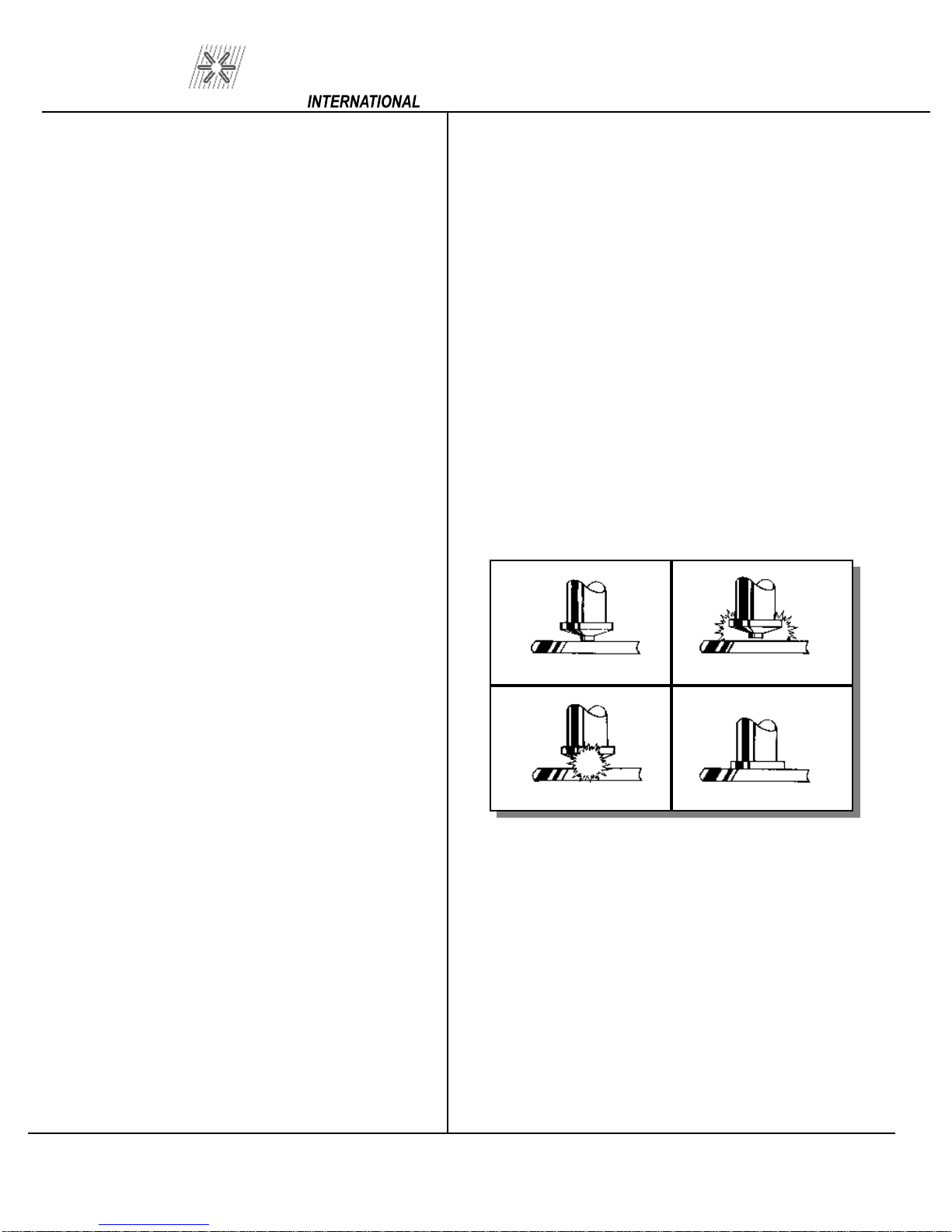
Initial Contact
3 4
Forced Into Molten Pool
(FIGURE 1 CONTACT CD WELD)
base material (SEE FIGURE 1). Verify that the gun is
held perpendicular to the work
di
porizes the tip. The proper tip design is critical. This
is what determines the length of time of the weld. An
arc is briefly sustained which melts the stud base su
face and the work surface directly underneath the
stud. The spring pressure in the gun then forces the
stud into the molten pool, completing the weld in a
proximately six milliseconds.
The stud is first placed in contact with the
scharges the capacitors through the stud which v
During Weld
After Weld
. Pulling the trigger
a-
r-
p-
PAGE 2

PRO WELD
T
his technique, when equipment is set up properly,
is simple and easily mastered. The same power su
ply is capable of welding many different sizes and
materials of fasteners. If you require assistance in
se
lecting the proper accessories, contact our cu
tomer service department or your field represent
tive.
7.0 POWER REQUIREMENTS
110 VOLT OPERATION
110 volt AC 60 H:
Internal :
circuit breaker
Integral 9 foot power cord
25 amp service
20 amp;
(P/N: 104-0021)
s-
a-
p-
CD-312
Capacitance:
88,000 uF nominal
Weld Mode:
Polarity:
Power Required:
Int
STANDARD GUN & CABLE SPECIFICATIONS
Contact
Straight or Reverse
110 Volt AC 60 Hz 25 Amp
ernal Fusing:
20 Amp Circuit Breaker
3AG 1 Amp 250 volt (2 on PC board)
IF EXTENSION REQUIRED
Cable Length
50
12’
25’
30’
110 Volt
#16/3
#16/3
#14/3
#12/3
8.0 SYSTEM SPECIFICATIONS
Weight:
48 Lbs.
Size:
Ch
Panel Controls:
Weldable Materials:
Brass, Zinc coated, Galvanized
Weldable Stud Diameter:
Weld Rate:
Weld Voltage:
45-
8 1/2” W x 10” D x 16 1/2” H
21.6 cm W x 25.4 cm D x 42 cm H
assis:
16 Ga. Steel (Painted International Orange)
Power
Voltage Control
Steel, Stainles
12 Ga. Through 3/8” Weld Base
(Max W.B. Dia.
24 per minute 5/16”
185 VDC
s steel, Aluminum, Copper,
For AL=5/16” {1/4” thread})
WELD GUN-LIGHT DUTY PRECISION
CD CONTACT
Part Number:
300 300-
Weight:
2 lbs. (not including cable)
(
Size:
Weldable Stud Diameter:
14 Ga. Thr
Material:
Integral Gun Cable Length:
Connectors:
Cables
Ground Cable:
lbs. (including 25 ft. #4 weld cable & 16
SOW control cable)
6 1/2” x 5 3/4” x 2”
High strength, impact resistant, glass fiber re
inforced polycarbonate
25 feet – #4 AWG
Male Camlok / 2 Pin Hubbell Male
(1) #4 x 15’
0100 B Collet Gun
0101 Taper Tip Gun
ough 1/4” Flanged
(P/N: 125-0100)
-4
-
PAGE 3
 Loading...