

Page 1

OPERATION/MAINTENANCE
MANUAL
Page 2

Page 3

PRO WELD
CD-212
1.0
2.0
3.0
4.0
5.0
6.0
7.0
8.0
9.0
10.0
TABLE OF CONTENTS
INTRODUCTION
WARRANTY
UNPACKING YOUR UNIT
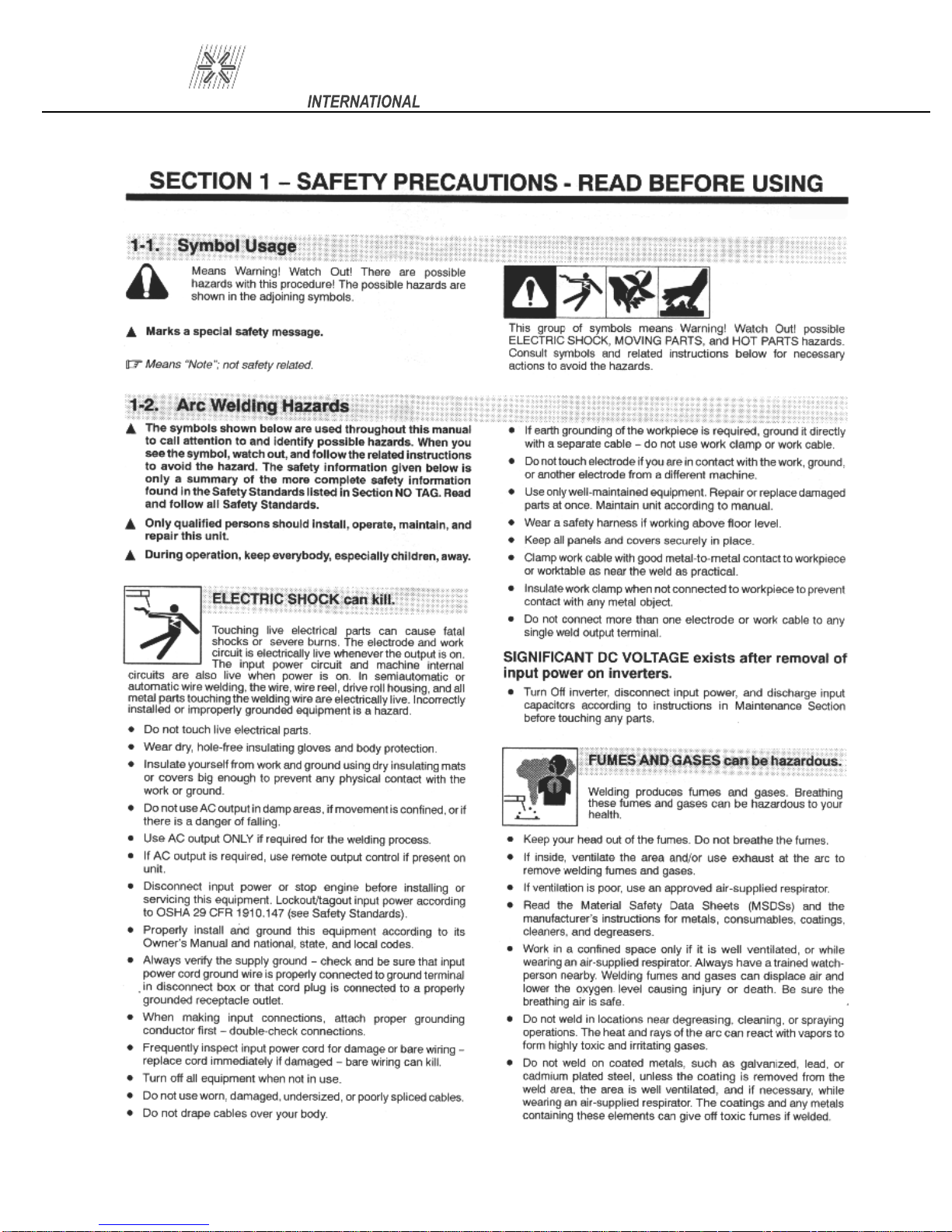
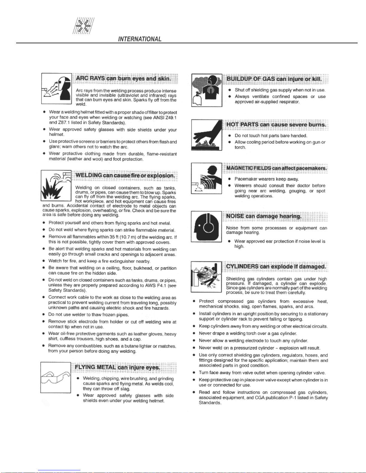
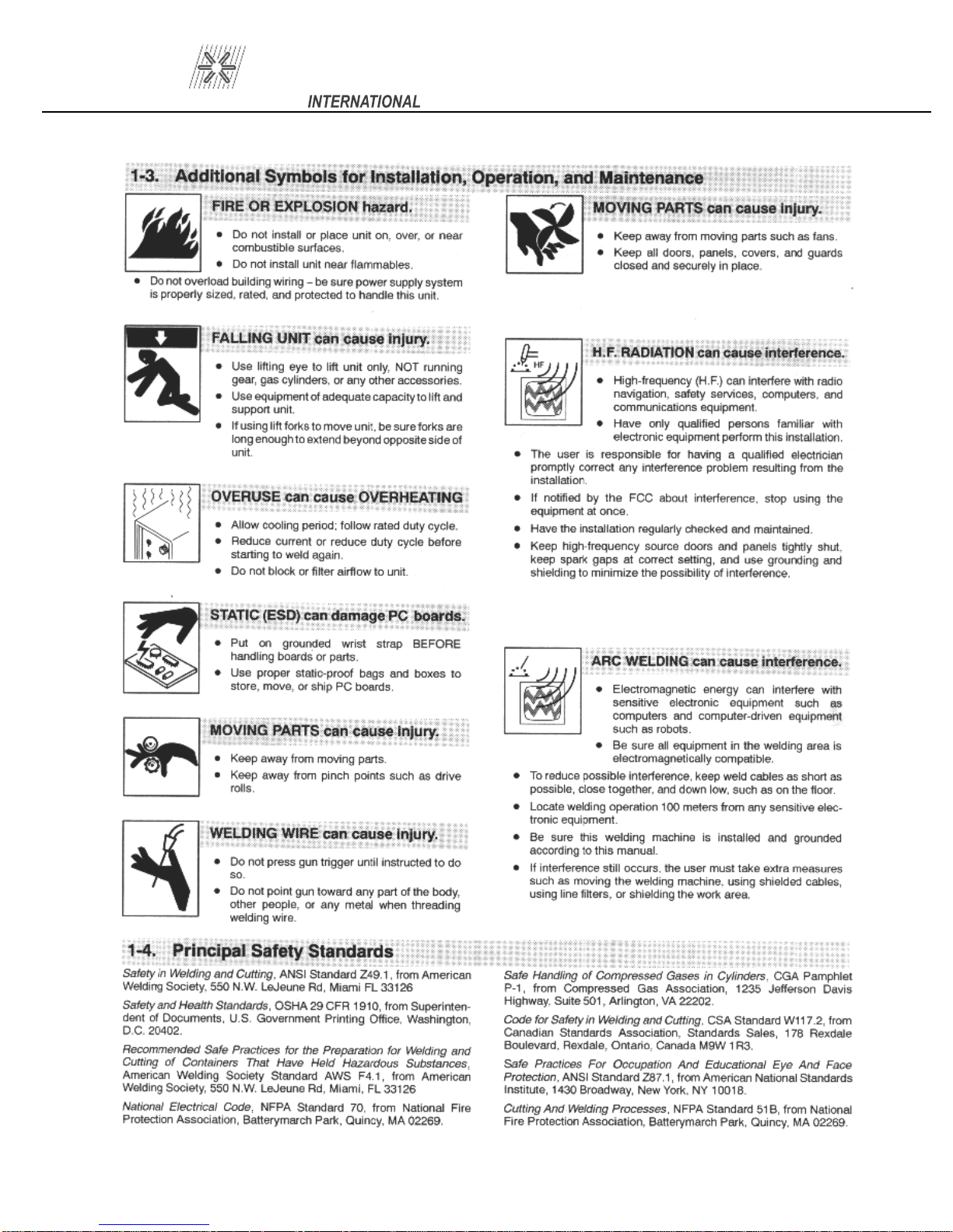
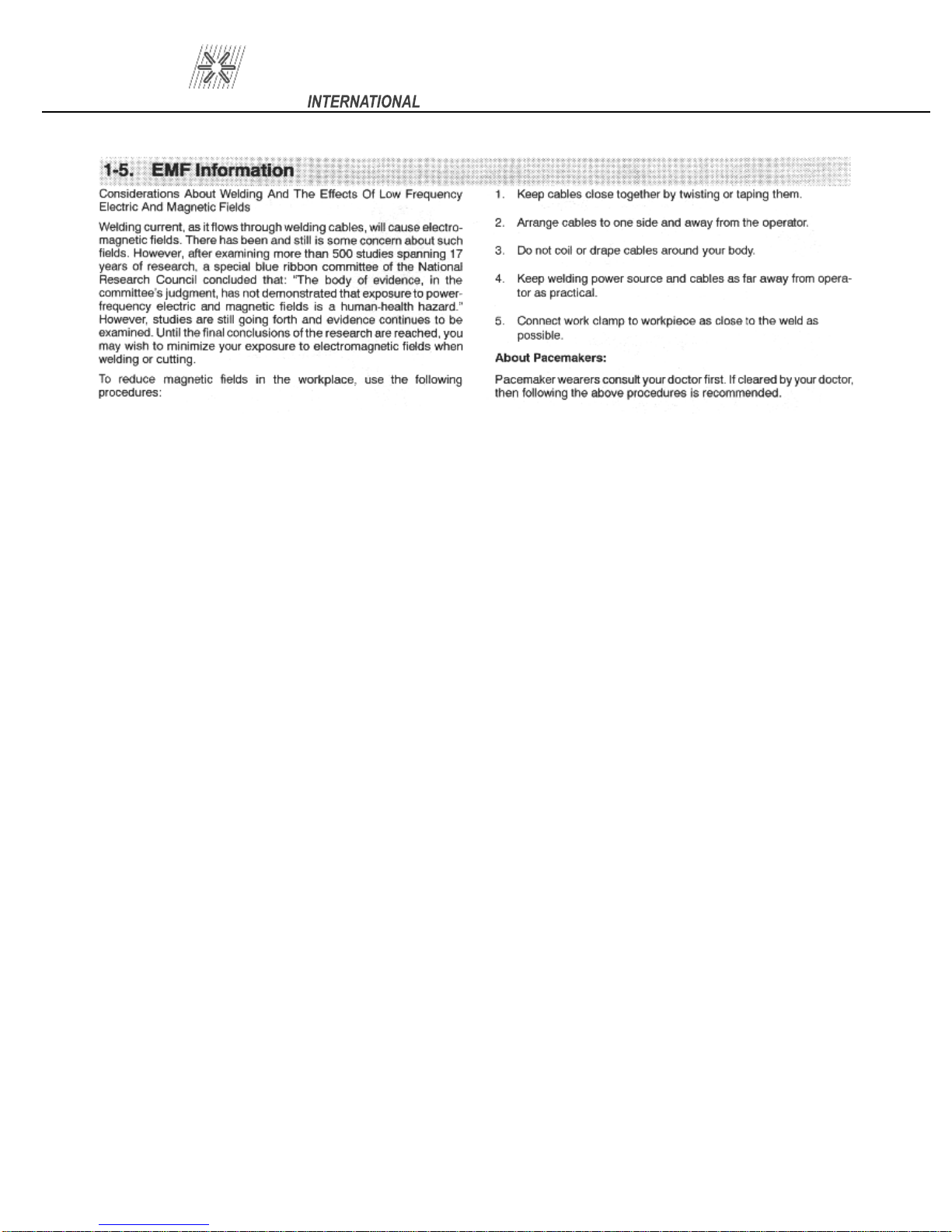
SUGGESTED SAFETY PRECAUTIONS
GENERA
L DESCRIPTION
THE CD WELDING PROCESS
POWER REQUIREMENTS
SYSTEM SPECIFICATIONS
WELDING SYSTEM HOOK-UP
9.1
9.2
Straight Polarity
Reverse Polarity
SYSTEM OPERATION
1
1
1
1
2
2
3
3
4
4
5
6
11.0
12.0
13.0
14.0
15.0
16.0
17.
18.0
19.0
GUN SET-UP
11.1
11.2
11.3
11.4
11.5
11.6
Standard
Installin
For Weld Pins with Collet Protector
Template Adapter
Collet Protector wi
Parts List LD CD Handgun
g or Changing Collets or Chucks
th Blunt Leg
WELDABLE MATERIAL COMBINATIONS
CAUSES OF POOR OR ERRATIC WELDS
TROUBLE SHOOTING POOR WELDS
ROUTINE WELDER MAINTENANCE
ASSEMBLY –CD-212 CONTROLLER
16.1
PC Boar
d Assembly Drawing
TROUBLE SHOOTING – ELECTRICAL
13
14
18
CHECK LIST CD-212 SYSTEM P.N. 100-0112
CHECK LIST CD-212 SYSTEM P.N. 100-0113
7
7
8
8
9
9
11
12
13
15,16
17
20
20
Page 4

PRO WELD
CD-212
LIST OF FIGURES
1
2 STRAIGHT POLARITY HOOK-UP 4
3
4
5 STANDARD GUN SETUP 7
6
7
8
9
10
CD CONTACT PROCESS
REVERSE POLARITY HOOK-UP
FRONT PANEL LAYOUT
COLLET PROTECTOR SETUP
TEMPLATE ADAPTER GUN SETUP
COLLET PROTECTOR/BLUNT LEG SETUP
LIGHT
HOT WELD
DUTY CD GUN
13
2
6
10
5
8
9
9
11
12
13
14
15
16
17
COLD WELD
ARC BLOW
WELD WITHOUT FOOTPIECE
GOOD WELD
PARTS LIST
PARTS LIST (continued)
PC BOARD
13
14
14
15
16
17
14
Page 5
PRO WELD
CD-212
Page 6
PRO WELD
CD-212
Page 7
PRO WELD
CD-212
Page 8
PRO WELD
CD-212
Page 9

PRO WELD
1
.0 INTRODUCTION
Your new stud welding equipment is carefully
constructed of the finest components and materials
available. Used
you years of profitable, efficient service.
The system incorporates the latest in enginee
ing advances, for completely reliable end welding of
mild steel, stainless steel, aluminum and lead free
copper and brass fasten
A careful study of this manual will enable you
to understand how the welder operates to insure
proper performance under al
properly, this equipment will give
2.0 WARRANTY
The electrical and mechanical components of
the stud welder are thoroughly performance i
spected prior to assembly in the welder. The asse
bled welder is completely performance checked. The
welder is delivered to you in functional electro
mechanical condition.
All p
arts used in the assembly of the welder
and its accessories are fully warranted for a period of
1 YEAR from the date of delivery
welding capacitors are warranted for a period of 1
YEAR from the date of delivery. The printed circuit
boards
for a period of 3 years.
the right to repair or replace, at their option, defe
tive parts which fail during the guarantee period.
No
ment
purchaser within ten (10) days after the defect is first
discovered. The manufacturer does not assume any
liability for paying shipping cost or any labor or m
terials furnished where such cost are not expressly
authorized in writing.
acces
abuse, improper installation, maladjustment, or use
not in accordance with the operating instructions fu
nished by the manufacturer. The warranty is valid
only when studs are purchased from sources a
proved by the manufacturer or are of identical spec
fi
used in all proweld equipment are warranted
Under the warranty, the manufacturer reserves
tice of any claim for warranty repair or replac
must be furnished to the manufacturer by the
The manufacturer does not warrant any parts or
sories against failures resulting from misuse,
cations to the manufacturer’s
ers.
l operating conditions.
. In addition, the
n-
m-
-
c-
e-
a-
p-
CD-212
3
.0 UNPACKING YOUR UNIT
possible to the point of installation before unpacking
it. Do not operate the unit from an extension power
r-
cord if possible. Once the unit is unpacked it is reco
mended that you inspect it for any physical damage.
inspected at the factory. Upon
hooked up to the recommended incoming power b
fore welding. We recommend that you check that you
have received all the items listed on the shipping
check list. (see SECTION 1
adequate ventilation. Do not restrict the air flow
through the side l
the control housing.
Upon receipt of your unit, place it as close as
Your unit has been completely assembled and
receipt, the unit must be
8 or 19)
Place the unit in a large enough area to provide
ouvers. Do not allow water to enter
4.0 SUGGESTED SAFETY PRECA
TIONS
ity of the welder to observe certain safety rules to i
sure his personal safety and to protect those working
near him.
Reference is directed, without endorsement or
recommendation, t
and Cutting, and to AWG Publication A6,1-66, Re
om
ing.
r-
i-
while welding or weld in the rain. Avoid wear-
In any welding operation, it is the responsibi
o ANSI Z49.1, Safety in Welding
mended Safety Practices for Gas-Shield Arc Wel
1. Always treat electricity with respect. Under
open circuit conditions, the welding machine
output voltage may be dang
2. Don’t work on live circuits or conductors.
Disconnect the main power line before check
ing the machine or perform
nance operations.
3. Be sure the welding machine cabinet is
properly grounded to a good electrical ground.
4. Don’t stand in water or on a damp floor
ing wet sweaty cloths when welding.
U-
erous.
ing any mainte
m-
e-
l-
n-
c-
d-
-
-
Page
1
Page 10
PRO WELD
5. Don’t operate with worn or poorly con
nected cables. Don’t operate weld gun with
loose cable connections. Inspect all cable
quently for insulation failures, exposed wires,
loose connections, and repair as needed.
6. Don’t overload welding cab
to operate with hot cables.
7. Don’t weld near flammable materials or liq
uids, in or near atmospheres, or o
ing explosive gases.
8. Don’t weld on containers which have held
combustible or flammable materials, or on ma
terials which give off flammable or toxic va
pors when heated, without proper cleaning,
purging, or inerting.
les or continue
n ducts carry
-
s fre
CD-212
T
he system comes complete with power cord, weld
-
-
-
-
-
cables and gun. Just add the accessories required for
the stud size to be welded. This manual should pr
vide all the information required for you to be able to
set up, weld, and maintain the CD-212 welding sy
tem.
6.0 THE CD WELDING PROCESS
common method of CD stud welding. Practically
foolproof, it produces no reverse side marking in
most cases and is suitable for most commercial and
industrial applications.
accessories for the length and diameter stud you are
going to weld. Refer to the CD Acc
and CD Stud Welding Gun Section for information
on accessories and gun set
Contact welding is the simplest and most
First
, the gun must be set
-up.
-up with the proper
essories Guide
o-
s-
9. Be sure t
when welding in confined spaces.
10. Never look at the electric arc without wear
ing protec
11. Always use the proper protective clothing,
gloves, ect.
12. Never strike an arc when near a bystander
who is unaware of the dangers of ultraviolet
light on their eyes.
5.0 GENERAL DESCRIPTION
CD-
tained heavy duty capacitor discharge power supply
capable of welding up to 1/4” flanged studs in mild
steel.
for longer life and has been designed for easy mai
te
nance and field service. This welder uses standard
110 volt AC line voltage.
212 HEAVY DUTY PORTABLE
CD ST
The CD-212 portable CD welder is a self co
The CD-212 utiliz
o provide for proper ventilation
tive eye shields.
UD/PIN WELDER
es a solid state control board
n-
n-
1 2
-
Initial Contact
3 4
Forced Into Molten Pool
(FIGURE 1 CONTACT CD WELD)
base material (SEE FIGURE 1). Verify that the gun is
held perpendicular to the work
di
porizes the tip. The proper tip design is critical. This
is what determines the length of time of the weld. An
arc is briefly sustained which melts the stud base su
face and the work surface directly underneath the
stud. The spring pressure in the gun then forces the
stud into the molten pool, completing the weld in a
proximately six milliseconds.
The stud is first placed in contact with the
scharges the capacitors through the stud which v
During Weld
After Weld
. Pulling the trigger
a-
r-
p-
Page
2
Page 11

PRO WELD
T
his technique, when equipment is set up properly,
is simple and easily mastered. The same power su
ply is capable of welding many different sizes and
materials of fasteners. If you require assistance in
se
lecting the proper accessories, contact our cu
tomer service department or your field represent
tive.
7.0 POWER REQUIREMENTS
110 VOLT OPERATION
110 volt AC 60 H:
Circuit protection:
(P/N: 104-0020)
Integral 9 foot power cord
IF EXTENSION REQUIRED
Cable Length
50
12’
25’
30’
20 amps;
15 amp circuit breaker
110 Volt
#16/3
#16/3
#14/
#12/3
8.0 SYSTEM SPECIFICATIONS
Weight:
26 Lbs.
Size:
Chassis:
Panel Controls:
Power
Weldable Materials:
Steel,
Brass, Zinc coated, Galvanized
Weldable Stud Diameter:
14 Ga. Through 1/4” Flanged
Weld Rate:
Weld Voltage:
45-
9” W x 11 3/4” D x 8 1/2” H
22.9 cm W x 29.8 cm D x 21.6 cm H
14 Ga. Aluminum (Painted International
Orange)
Voltage Controls
(Max W.
12 per minute
Stainless steel, Aluminum, Copper,
B. Dia. For AL=5/16” (1/4” thread)
200 VDC
3
s-
a-
p-
CD-212
Weld Mode:
Polarity:
Power Required:
Circuit Protection:
3AG 1 Amp 250 volt fuses
STANDARD GUN & CABLE SPECIFICATIONS
WELD GUN-LIGHT DUTY PRECISION
CD CON
Part Number:
300 300-
Weight:
2 lbs. (not including cable)
Size:
Weldable Stud Diameter:
14 Ga. Through 1/4” Flanged
Mate
Integral Gun Cable Length:
Conn
Cables
Ground Cable:
Contact
Straight or Reverse
110 Volt AC 60 Hz 20 Amp
15 Amp circuit
(2 on PC Board)
( lbs. (including 25 ft
SOW control cable)
6 1/2” x 5 3/4” x 2”
rial:
High strength, impact resistant, glass fiber re
inforced polycarbonate
25 feet – #4 AWG
ectors:
Male Camlok / 2 Pin Hubbell Male
(1) #4 x 15’
breaker
TACT
0100 B Collet Gun
0101 Taper Tip Gun
(P/N: 125-0100)
. #4 weld cable & 16
-4
-
Page
3
Page 12
PRO WELD
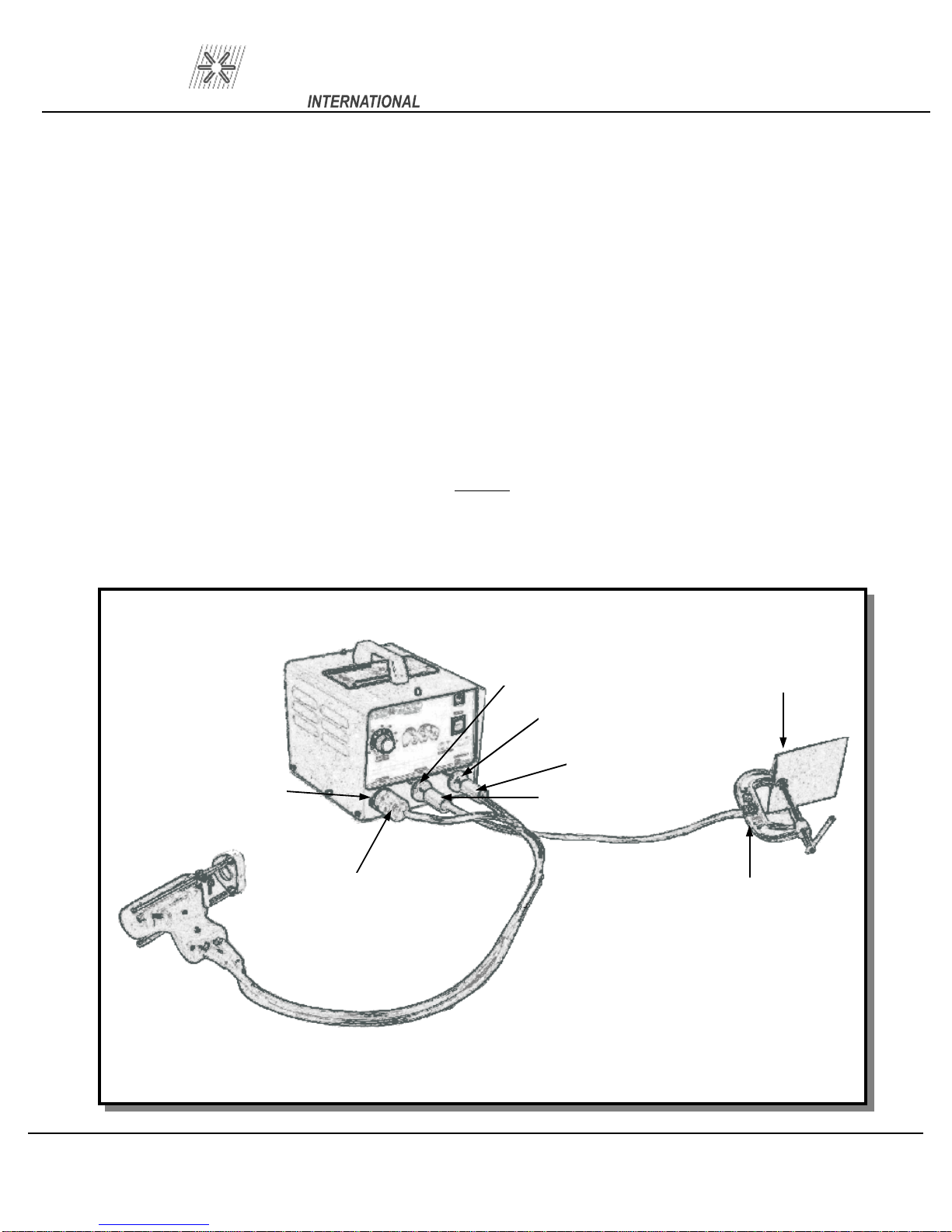
9.0 WELDING SYSTEM HOOK-UP
9.1
A. Connect ground cable connector (1A) into c
receptacle marked GROUND. Twist until it locks. Attach “C” clamp (2) to the w
(CLEANED AREA).
B. Connect the gun control cable (3A) into the female receptacle (3).
C. Connect the gun weld cab
locks.
D. Connect AC power cable to AC outlet.
The
welding cables are coiled.
Straight Polarity (Standard Set-Up) (see Figure 2)
le (4A) into the receptacle marked GUN (4). Twist clockwise until it
gun welding and control cables must be laid out in a straight line. Poor weld quality may result if
CD-212
amlok (1). The camlok should be connected into the
orkpiece (5)
NOTE:
1
4
4A
3
3A
Figure 2 Straight Polarity Hook-Up
1A
5
2
Page
4
Page 13
PRO WELD
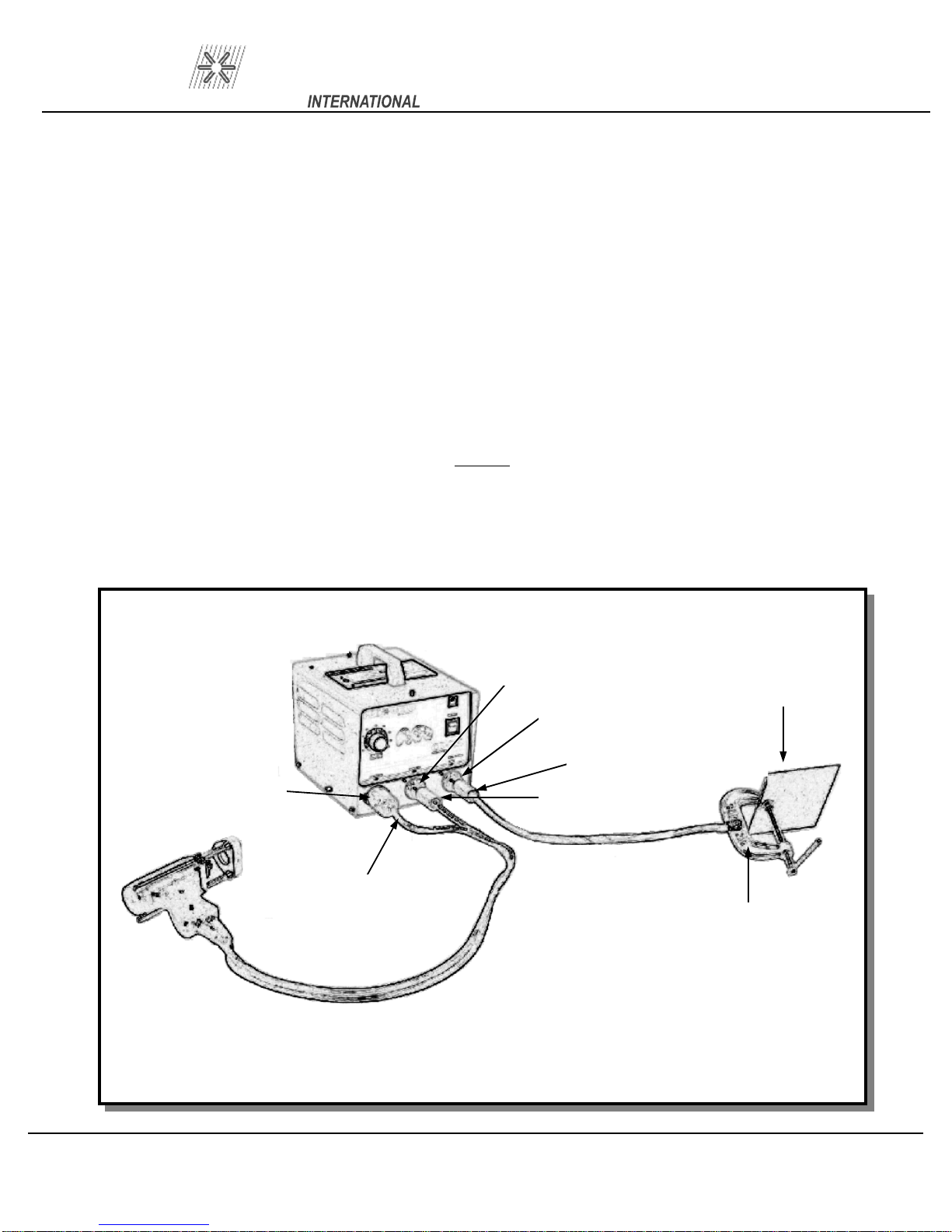
9.2 Reverse Polarity (Recommended for brass or galvanized) (see Figure 3)
A. Connect ground cable connector (1A) into camlok (
receptacle marked GUN. Twist until it locks. Attach “C” clamp (2) to the workpiece (
AREA).
B. Connect the gun control cable (3A) into the female receptacle (3).
C. Connect the gun weld cable (4A) in
it locks.
D. Connect AC power cable to AC outlet.
The gun wel
welding cables are coiled.
ding and control cables must be laid out in a straight line. Poor weld quality may result if
to the receptacle marked GROUND (1). Twist clockwise until
CD-212
4). The camlok should be connected into the
5) (CLEANED
NOTE:
1
5
4
1A
3
3A
Figure 3 Reverse Polarity Hook-Up
4A
2
Page
5
Page 14
PRO WELD
1
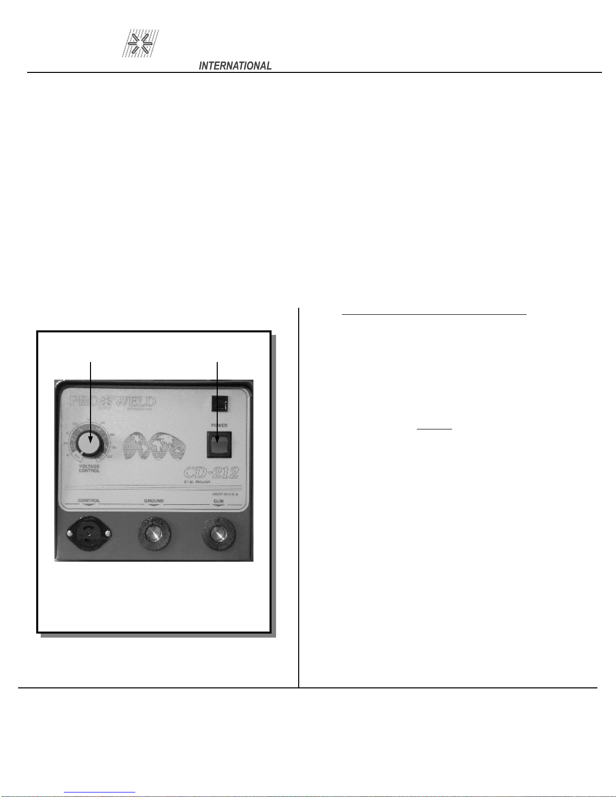
0.0 SYSTEM OPERATION
1.
2.
the front panel.
3.
to the lowest setting.
4.
tion. The integral indicator light (1) will turn on.
(see Figure 4)
The CD-212 is designed for simple, yet precise operation.
It has an “ON-OFF” rocker
Before turning the unit “ON”, the vo
With all cables connected, turn the unit on by putting the rocker switch (1) in the “ON” pos
2 1
switch/indicator light (1) and a variable voltage control dial (2) on
ltage control knob (2) should be turned counter-clockwise
CD-212
i-
S
etting the Weld Voltage/Capacitance
clockwise to increase the weld voltage until the
indi
number for the particular stud size that you are
welding. (See the set up information
Below).
Once the voltage control knob is set to
a higher setting, turning it counterwill NOT reduce
bank, until the toggle switch (1) is turned
“OFF” (for approximately 10 seconds).
Slowly turn the voltage control knob
cator knob is pointing at the appropriate
chart,
NOTE:
clockwise
the voltage on the capacitor
Figure 4 Front Panel Layout
Page
6
ages corresponding to various stud sizes. The
approximate voltages for each stud size is as
follows:
45-
80-
120-
160-
The settings are marked with the vol
45 VDC
200VDC
80 VDC
120 VDC
160 VDC
190 VDC
1
#8
#10
Min.
2 ga./#6
1/4”
MAX.
t-
Page 15
PRO WELD
11.0 GUN SET-UP
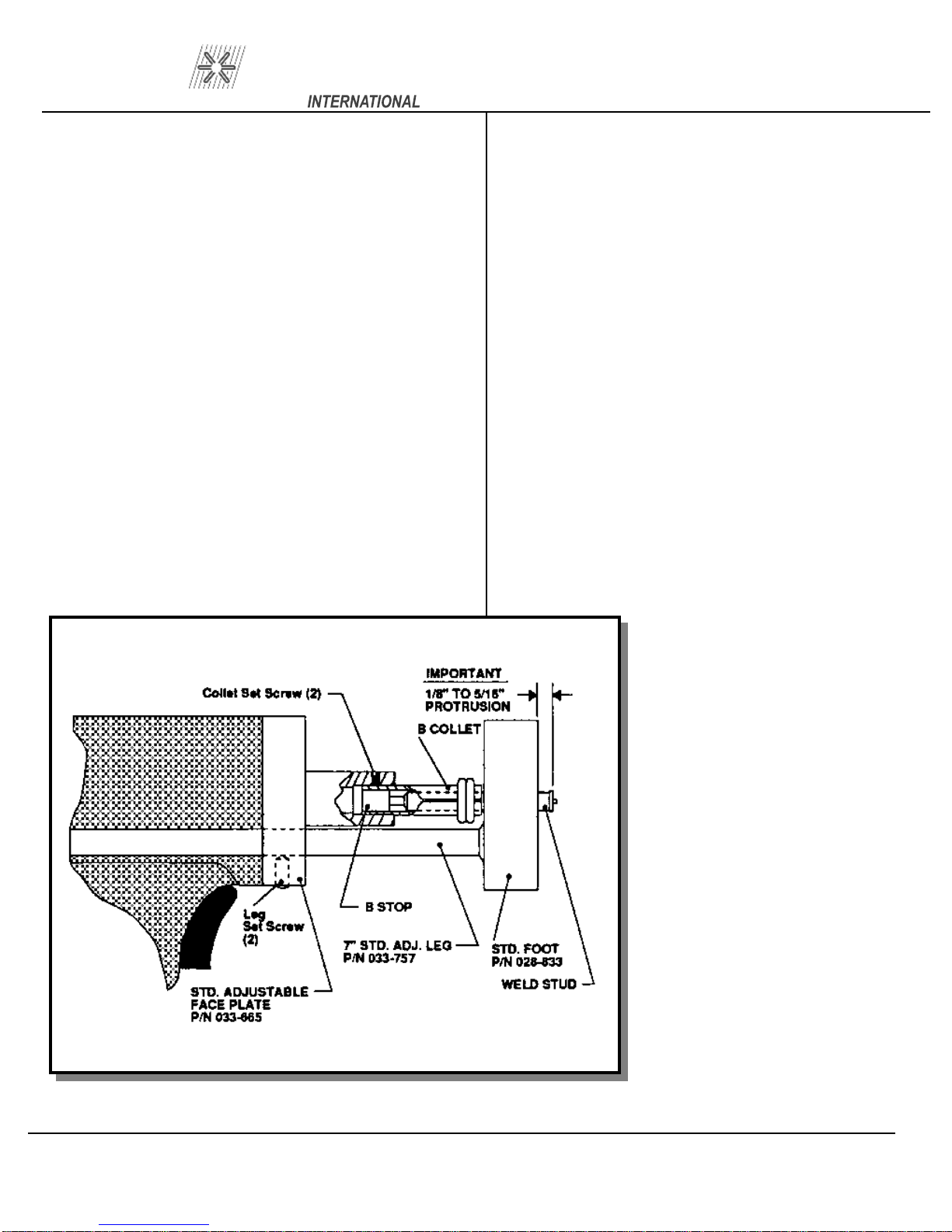
11.1 STANDARD (see Figure 5)
The standard gun set-up is used for welding the
majority of applications. It co
adjustable face plate, two legs, a foot, B-collet, stop,
and spring for your specific stud size.
A step
to set-up and operate the standard CD gun.
To prepare for stud welding, it is necessar
have the proper accessories for the stud to be
welded. Those required are the legs, footpiece,
spring, collet, and appropri
A 3/32” and a 5/32” hex wrench are the only tools
needed for the adjustment of the gun.
-by-
step explanation of the correct way
nsists of the standard
y to
ate screws and washers.
CD-212
For CD welding, the stud normally should be
engaged for all but 1/4” of its length, whenever po
si
ble. Selecting the proper stop will accomplish this
for you. The objective of the collet is to maintain a
firm grip on the faste
and a good electrical connection, yet allow for ease
of loading.
made, assembly may begin. The footpiece is
mounted on the legs using 10-32 x 3/4” socket head
cap screws, inse
the footpiece. These holes are recessed so that the
head of the screws will not protrude.
the collet and stop into the open end of the gun shaft.
Secure the collet in p
shaft. Locate the legs, with footpiece attached, in the
Once the selection of the cor
After assembling the legs and footpiece, insert
ner to assure correct alignment
rect accessory is
rted through the holes at the base of
lace with two set screws on the
s-
Figure 5 Standard Gun Setup
h
oles provided in the gun faceplate. (It
may be necessary to back off the
socket screw in the faceplate to allow
the legs to ente
opening of the footpiece around the
weld end of the fastener. Tighten the
footpiece in position at this time. A
justment for the plunge which is the
distance the stud protrudes beyond the
end of the footpiece can now be made.
This is done b
32 x 1/4” set screws at the bottom of
the faceplate using the 3/32” Allen
wrench. Then sliding the legs f
proper adjustment. Refer to the set
chart for correct plunge distance (from
1/8” to 5/16”).
Correct set-up on all CD
5/16” plunge. This must be assured for
proper weld results in all cases.
r the hole). Center the
y loosening the two 10
or
-up
NOTE:
units is 1/8”
d-
-
-
Page
7
Page 16
PRO WELD
The gun is now ready to weld. Select the
proper setting for the size stud to be welded. Voltage
is determined by the weld base d
your power source is set for the proper polarity:
straight for steel, reverse for galvanized.
11.2 INSTALLING
OR CHUCKS
( The terms collet or chuck are different names for
the same device). The collet holds the pin or
be welded. It is secured to the gun shaft by two set
screws. These screws are loosened to remove or r
place a collet. Tighten these screws snugly to secure
the collet in place.
weldin
collet. If a collet becomes damaged or broken, it
must be replaced. You may also need a stop.
When you change the size of the stud you are
g, you must also change to the appropriate
OR CHANGING COLLETS
iameter. Be sure
stud to
e-
CD-212
therefore, the same setup is applicable
There are two standard sizes
And 10 ga. It is used with the round faceplate and
three blunt legs. The collet protector slides over the
coll
screws. The insert, which takes the place of the I
teral stop, is replaceable.
The stud is pushed into the chuck until the flange bo
toms out on the insert. The collet protector is not
available for studs larger than 10 ga.
1. It does not require a pin stop.
for a range of pin lengths.
2. There is a fixed
adjustments necessary.
3. It provides stability at the weld end
of the pin.
et and fastens to the chuck with three allen set
plunge, no gun
available: 12 ga.
n-
t-
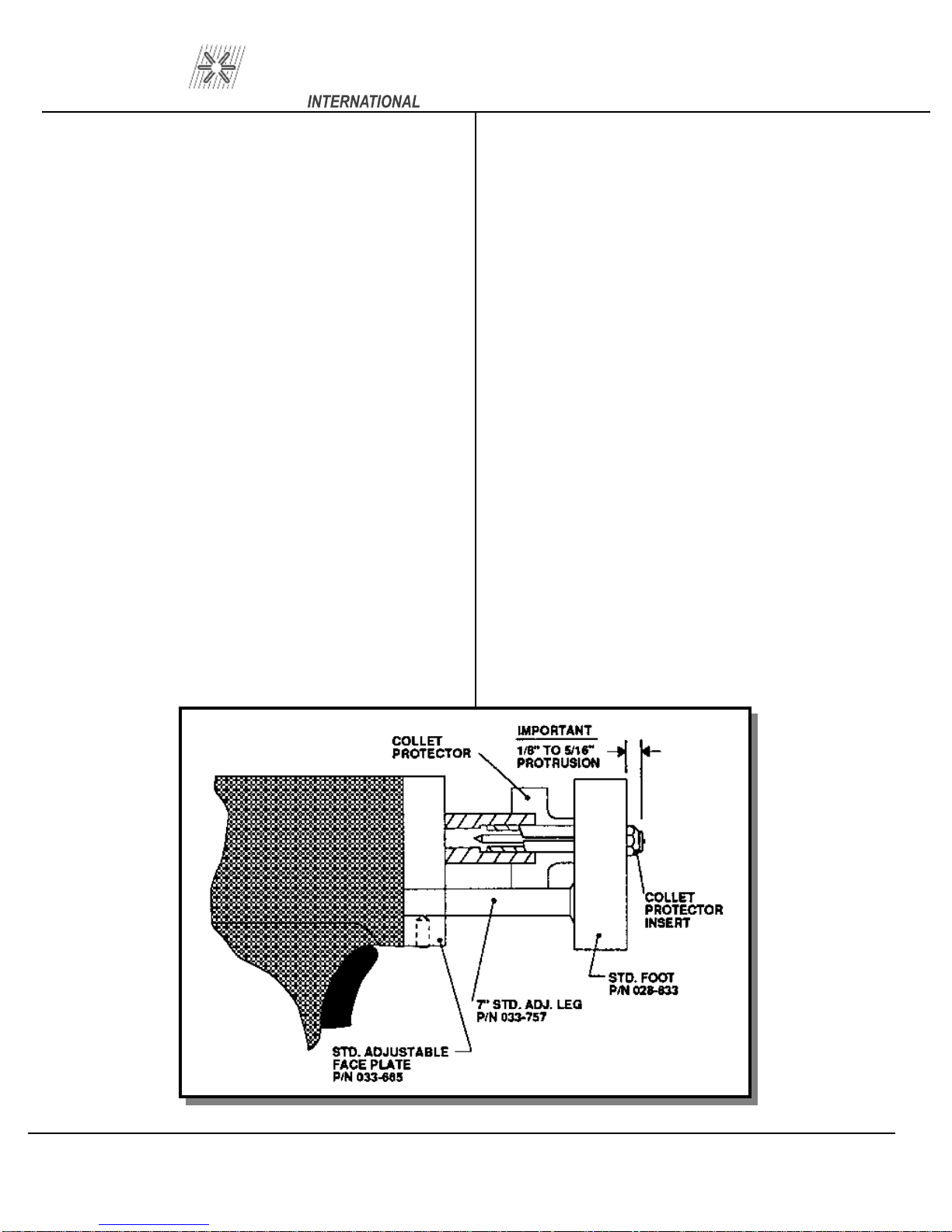
11.3 GUN SET-UP FOR WELD PINS WITH
COLLET PROTECTOR (see Figure 6)
The collet protector has several advantages
over the standard set
-up.
combination can alternately be used with the collet
protector as shown in Figure 10.
The standard adjustable legs and footpiece
Figure 6 Collet Protector Gun Setup
Page
8
Page 17
PRO WELD
1
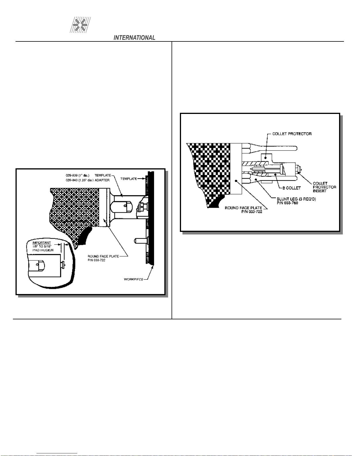
1.4 TEMPLATE ADAPTER (see Figure 7)
The template adapter is used when precise
location or positioning of the CD stud is requir
It is used with the round faceplate and does not r
quire a footpiece or legs. The adapter is fastened to
the faceplate and provides a fixed distance b
tween the collet and work. The plunge is set by u
ing the correct stop in the collet. A template can
then be fabricated to enable very precise locating
of a particular stud.
The template adapter is available in two
sizes, (1” and 1-1/4” diameter).
ed.
e-
e-
s-
CD-212
1
1.5 COLLET PROTECTOR/BLUNT LEG
nately be used with the collet protector as shown in
Figure 8.
(see Figure 8)
The round faceplate, with blunt legs, can alte
r-
Figure 7 Template Adapter gun setup
Figure 8 Collet Protector/Blunt Leg Setup
Page
9
Page 18
PRO WELD
CD-212
Page
10
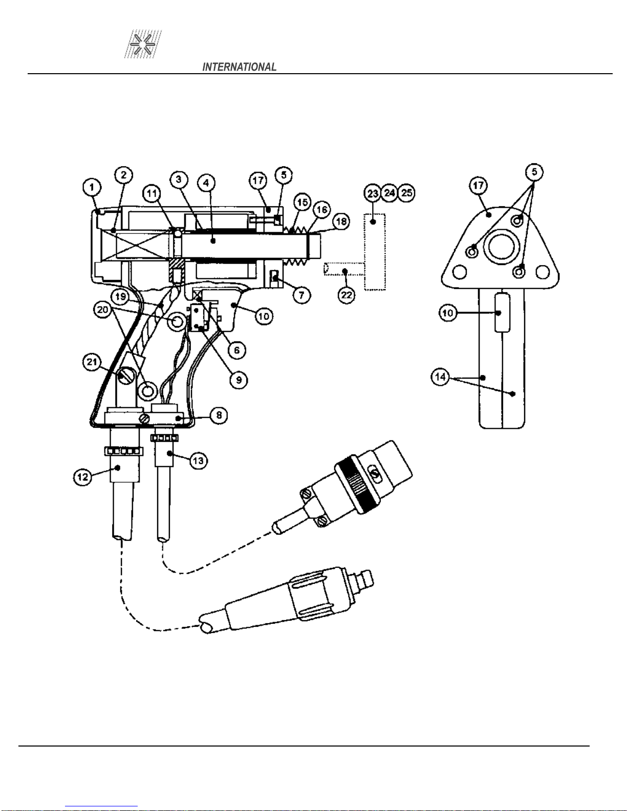
Figure 9 Light Duty CD Gun
Page 19

PRO WELD
11.6 PARTS LIST LIGHT DUTY CD HANDGUN
Part No. 300-0100
ITEM
PART NO.
DESCRIPTION
CD-212
QTY
1 033-384
2 001-800
3 033-610
4 033-799
5 033-016 HEX HEAD CAP SCREW
6 033-382
7 049-955
8
9 033-404
10 033-381
11 036-496
12 033-662-25
13 033-658-25 GUN CONTROL CABLE (25 FT.) 1
14 033-881
NOT USED
GUN (CD) REAR CAP MOLDED
SPRING MAIN HEAVY SILVER
GUN (CD/DA) BEARING ASSEMBLY
GUN (CD) SHAFT TUBE
GUN (CD/DA/FA) TRIGGER SPRING
M SCREW SET MS, BRASS PLT
GUN (CD/DA/F
TRIGGER SWITCH
GUN (CD/DA/FA) TRIGGER BUTTON MOLDED
GUN
(FL) SHAFT BLOCK – A
GUN WELD CABLE (25 FT.)
GUN
BODY RH & LH STD.CD MACHINED
A) CABLE CLAMP (ALUM. BLOCK)
1
3
1
1
1
1
1
2
1
1
1
1
1
15 033-445
16 033-447
17 033-665
18 033-446
19 033-608
20 018-375
21 016-876
22 033-757
23 009-929
24 016-378
25 028-833
GUN (CD/FL) SHAFT BOOT ASSY
GUN (CD) SHAFT BOOT RETAINING RING
GUN (CD) FACEPLATE – STD. ADJUSTABLE
GUN (CD) SHAFT BOOT SNAP RING
GUN (CD) WELD PIGTAIL
SCREW PAN HEAD
WASHED, LOCK INTO. TOOTH
LEG (CD) STD.ADJ. 7”
FLAT WASHER
SOCKET HEAD CAP SCREW
STD. FOOTPIECE
2
ASSY
1
1
1
1
1
1
2 REF.
2 REF.
2 REF.
1 REF.
Page
11
Page 20

PRO WELD
CD-212
12.0 WELDABLE MATERIAL COMBINATIONS
Structural Steel (
Aluminum – Most alloys of the
1100, 3000 and 5000 series.
Zinc All
BASE MATERIAL
Mild Steel (1008-1018)
Galvanized Sheet (duct-”Q” Decking
Must Be Clean
oys (Die Cast)
)
STUD MATERIALS
Mild Steel 1008, 1018
Stainless Steel 304, 305
Brass 65
Copper, Silicon/Bronze
Mild Steel 1008
Stainless Steel 304,305
Mild Steel 1008,1018
Stainless Stee
Brass 65
Aluminum 1100,5356
Aluminum 1100, 5356
-35, 70-30
-35, 70-30
-1018
l 304,305
Medium Carbon Steel (1030-1018)
Lead Free Brass
Lead Free Rolled Brass
Elec
trolytic Copper
Mild Steel 1008, 1018
Stainless Steel 304,305
Brass 65
Mild Steel 1008, 1018
Stainless Steel 304, 305
Copper, Silicon/Bronze
-35, 70-30
Page 12
Page 21
PRO WELD
1
3.0 CAUSE OF POOR OR ERRATIC
WELDS
CD-212
12. Incorrect spring. (REPLACE WITH PROPER
SPRING)
1. Loose collet. Does not grip stud tightly.
(REPLACE) Not enough engagement of stud to co
let. (CHANGE STOP)
2. Fault or loose ground connection. (REPAIR OR
TIGHTEN)
3. Poor surface condition of base material, excess
oil, grease, rust, ect. (CLEAN)
4. Voltage or capacitance setting too low or too high.
(ADJUST TO DIAMETER OF STUD)
5. Broken or loose cables. (REPAIR)
6. Dirt in gun. (CLEAN)
7. Incorrect polarity. (CABLES HOOKED-UP
WRONG)
8. Use of center punch
USE CENTER PUNCH OR DEEP SCRIBES)
or deep scribe. (DO NOT
l-
ive
13. Poor stud quality.
14.0 TROUBLE SHOOTING POOR
WELDS
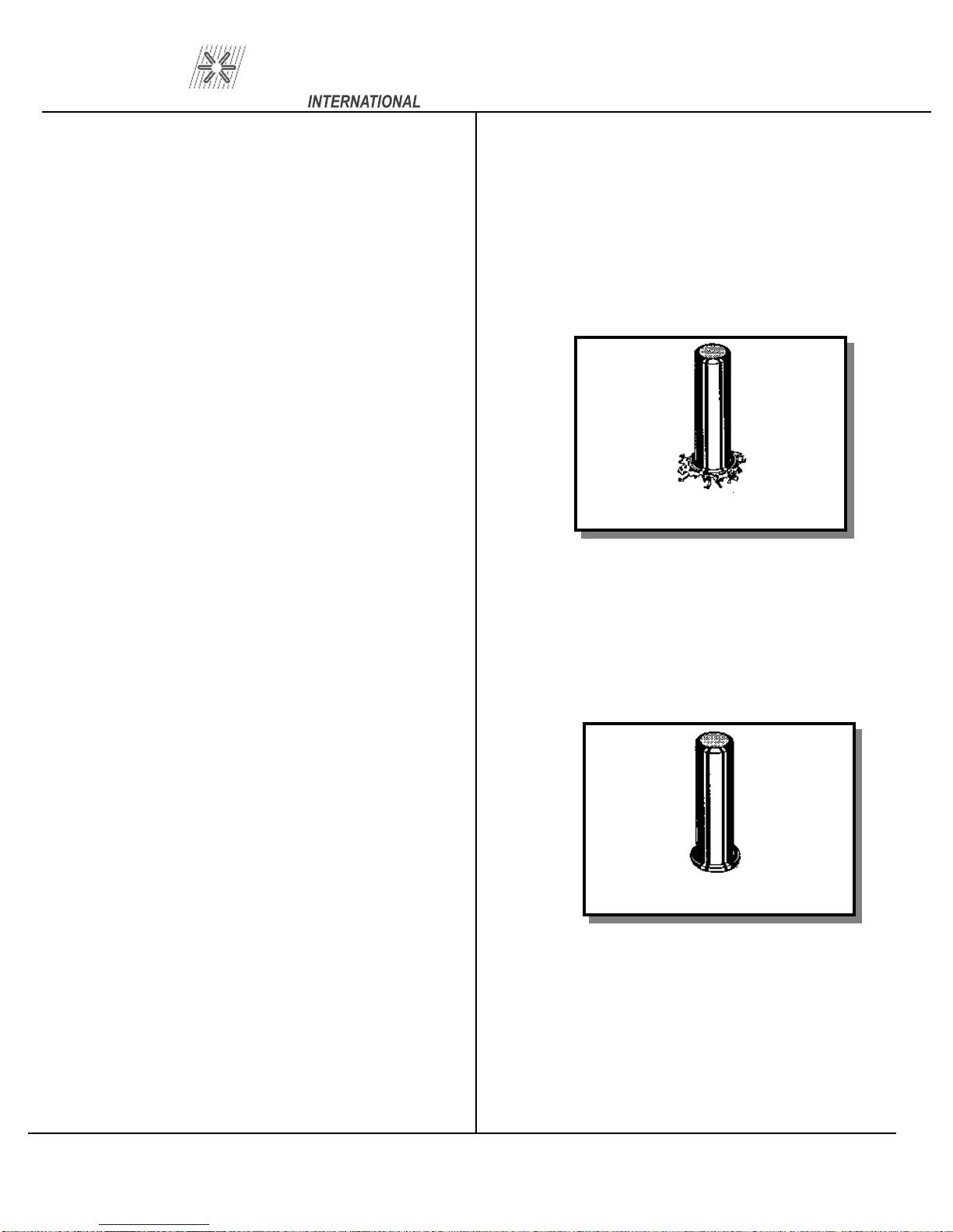
Figure 10 Weld too Hot
Weld too Hot
A) Decrease voltage.
B) Decrease capacitance.
C) Increase stud protrusion.
D) Increase spring pressure.
9. Cables too closely coiled.
10. Arc blow is evidenced by “one side
severe cases there will be no melting under one edge
of flange while the opposite side is gouged out or
ap
pears excessively hot. The principle cause of arc
blow is magnetic field induced by the current flow
during the weld. It occurs most often on long, na
row strips of metal or near edges of sheets or plates.
In some cases, a change in grounding positions, or
two grounds on the wor
edge of work, will correct the problem. For assi
tance in severe cases, contact your local sales repr
sentative.
11. Incorrect plunge setting. (ADJUST TO PROPER
SETTING)
” welds. In
r-
k piece, one at each end or
s-
e-
Figure 11 Weld too Cold
Weld too Cold
A) Increase voltage.
B) Increase capacitance.
C) Decrease stud protrusion.
D) Decrease spring pressure.
Page
13
Page 22
PRO WELD
CD-212
1
5.0 ROUTINE WELDER
MAINTENANCE
with minimum care. Ordinary common sense maint
nance will keep it operating efficiently.
Your CD-212 is designed for long service
e-
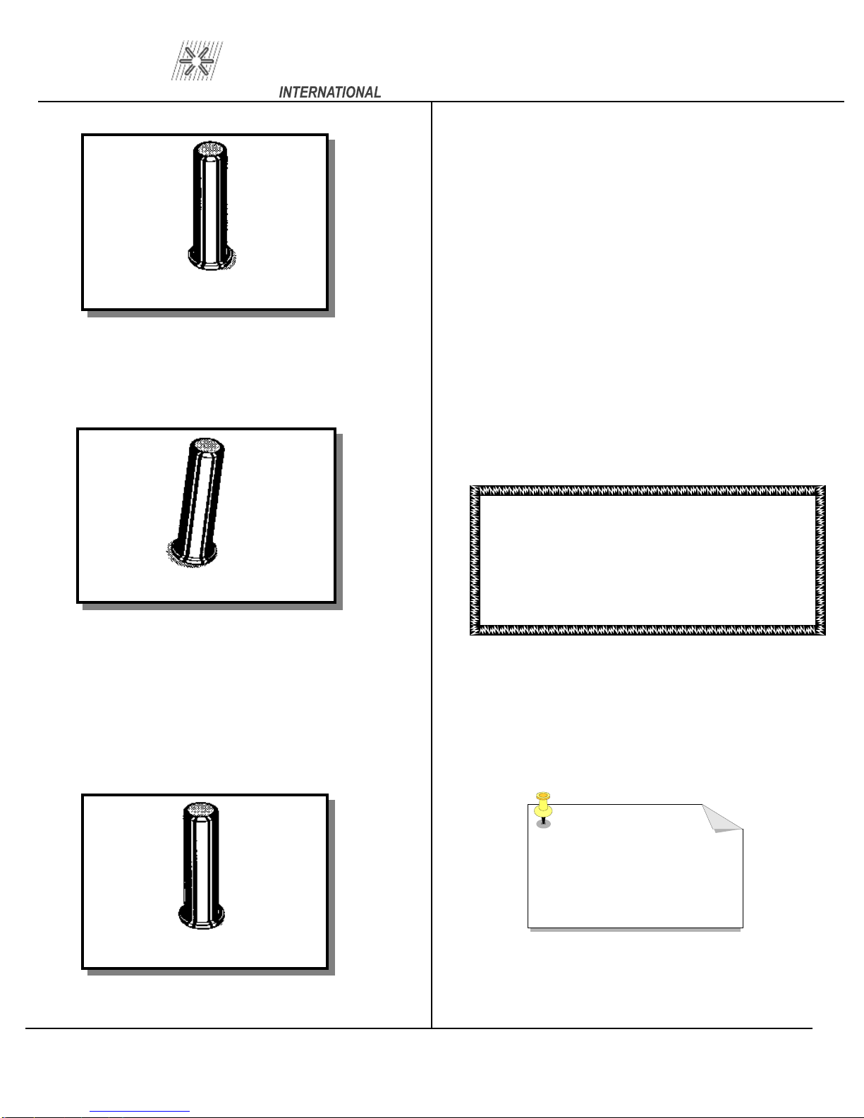
Figure 12 Arc Blow
Arc Blow
A) Use double grounds.
B) Ground too close or not spaced
Figure 13 Weld without footpiece
Weld without footpiece
A) Use standard footpiece.
B) Use template adapter.
C) Use tripod blunt legs.
bles with respect. Avoid sharp bends and kinks which
may break the cables. Don’t use the cables as a “tow
line” to move the cont
the cables where they enter the gun or at the conne
tors.
the cover of the controller and clean with air and a
soft brush around the
3.
weld cable connections and make sure all the screws
on the capacitor terminals are t
pounds.
1. Treat the welding, ground, and control c
rol. Avoid damage or straining
2. It is good practice to occasionally remove
components.
CAUTION
Be sure the controller is disconnected
from the power before removing the pro
tective cover.
While the cover is removed, tighten all the
orque to 30 inch
a-
c-
-
-
Figure 14 Good Weld
Page
14
NOTE:
Keep the gun free of
dust, dirt or foreign
material
Page 23
PRO WELD
CD-212
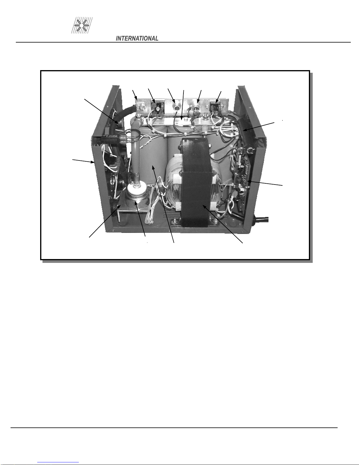
16.0 ASSEMBLY CD-212 CONTROLLER
11
12
13
13a
1
10
(see Figure 15,16, & 17)
9
8
7
6
2 3
4 5
Figure 15 Parts List
ITEM
1
2 SCR Mounting 124-0026
3
4
5
6
7
8
9
10
11
12
13
13a
DESCRIPTION
Chassis
Main SCR
Capacitor (3)
Transformer 105-0017
PC Board
Discharge Resistor
Safety Discharge SCR
Charging SCR
Buss Ba
Diode
Charging Bridge
Buss Bar
150K 2 Watt
101-0025
108-0001
600-0013
r 124-0034
108-0027
124-0035
111-0002
106-0023
112-0041
108-0042
108-0002
108-0017
PART NUMBER
Page
15
Page 24
PRO WELD
14
CD-212
18
17
16
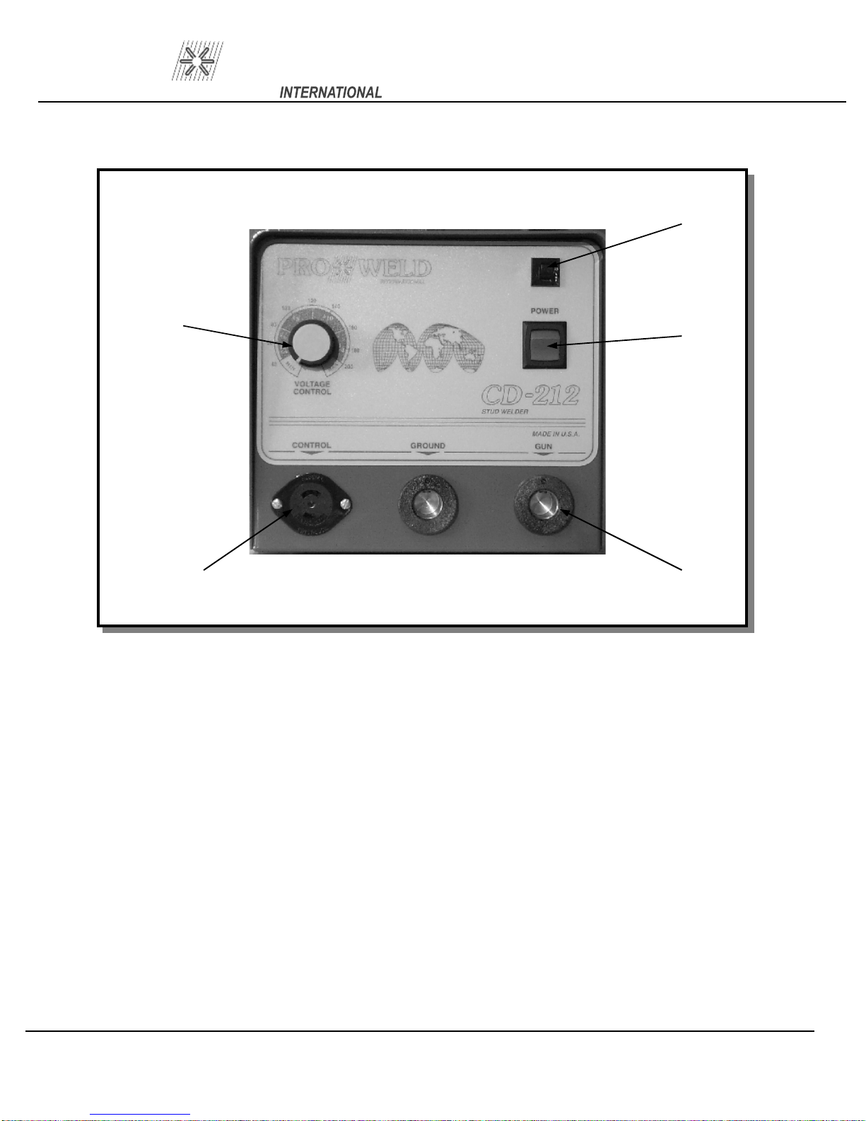
Figure 16 Parts List
ITEM
14
15
16 217
18
DESCRIPTION
Knob
Female Camlok (2)
Power Switch
Circuit Breaker
102-0060
107-0002
Pole Female Hubbell
104-0013
104-0020
107-0031
PART NUMBER
15
Page
16
Page 25
PRO WELD
CD-212
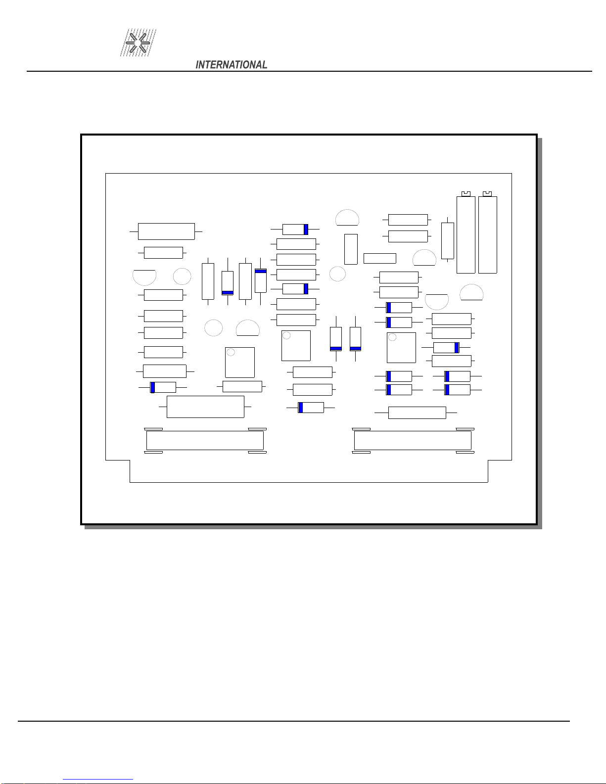
16.1 PC BOARD ASSEMBLY DRAWING
FU1 and FU2 are 3AG 1 ampere fuses
C4
+
R23
C7
+
V6
+
R21
R22
R20
R25
C8
D9
C3
R15
C6
D7
+
OP1
R24
V5
R14
ZD2
ZD1
R10
R8
R17
D6
R16
R18
OP3
R26
R19
D8
V4
C2
C5
+
D5
D4
C1
R11
R7
R5
R4
D2
D1
OP2
D10
D11
R1
V1
V3
D3
R6
R12
R3
R2
D12
D13
R9
V2
R13
F2
Figure 17 PC Board
F1
Page
17
Page 26

PRO WELD
CD-212
17.0 TROUBLE SHOOTING – ELECTRICAL
When troubleshooting the power unit/controller (welder), the following precautions must be
1. Welder must be TURNED OFF!
2. Unplug power cable from welder and wait at least two minutes before checking compo
3. The use of a volt/ohmmeter is recommended where any voltage may be present.
4. Use a continuity tester ( or troubles
5. Possible causes marked with a star (*) are generally the most common problems.
P
ROBLEM
1. Welder does not turn on
and
loose wire connection in
the plug.
will not weld.
hooting light) for continuity checks only.
POSSIBLE CAUSE
A. Power connections at
Welder or 110 VAC outlet
not complete.
*B. Broken power cable or
C. Fuse blown.
CORRECTIVE ACTION
Check connections.
Check wires for continu
Repair break.
Replace fuse.
observed:
nents.
ity.
2. Fuse bl
unit is turned on.
ows each time
Rupture hole. Replace
*A. Shorted weld capacitor.
B. Shorted rectifier (BR1)
C. Incorrect primary hookup.
D. Shorted transformer
assembly.
Check safety vent seal for
defective capacitor.
Check for a short across the
rectifier with ohmmet
Replace rectifier module if
shorted.
Check transformer connect
Replace transformer.
er.
ions.
Page
18
Page 27

PRO WELD
CD-212
PROBLEM
3. Welder turns on but
does not operate
*B. Broken gun control cable
or loose wire c
in either direction). Replace
4. Weld is excessively hot
regardless of vo
setting.
A. Ground cable connections
ltage
In either direction). Replace
POSSIBLE CAUSE
not complete.
in the plug. Shorted or
open trigger swit
*C. Faulty printed circuit
board.
D. Sh
A. Shorted charge SCR.
orted weld SCR.
onnection
ch.
CORRECTIVE ACTION
Check for continuity
Check continuity between
pins on control plug while
trigger is depressed.
Should read continuity.
Replace with new PC
Board.
Check with ohmmeter
(should not show continuity
rectifier module if shorted.
Check with ohmmeter
( should not show continuity
if shorted.
5. Poor and erratic
welding.
*B.
Faulty printed circuit
board.
C. Open voltage
potentiometer.
A. Improper gun setup.
B. Improper grounding or
cable setup or incorrec
polarity.
C. Weld cables are coiled.
D. Incorrect voltag
E. Studs or pins not
perpendicular to work
surface.
e setting.
t
Replace defective legs.
Replace with new PC
Board.
Replace defective voltage
Potentiometer.
Check applicable gun setup
Instruction page.
Check applicable cable setup
Instruction page.
Straighten out cables.
Adjust as necessary.
Adjust legs as necessary.
Page
19
Page 28

PRO WELD
18.0 CHECK LIST CD-212 SYSTEM PT. NO. 100-0112
STANDARD CD-212 WELDING SYSTEM COMPLETE WITH B-COLLET GUN
AND 25’ #4 GROUND CA
ITEM
1. CD-
2.
3. GROUND CABLE #4 X 15’ 125-0100 1
4.
5.
19.0 CHECK LIST CD-212 SYSTEM PT. NO. 100-0113
DESCRIPTION
212 CONTROLLER 110 VAC
GUN ASSY. B-COLLET w/INTEGRAL 2
& CONTROL CABLE 2-LEGS, and FOOTPIECE
MANUAL,
HEX WRENCH SET
Operation and Maintenance CD
BLE
200-0015 1
5 FT.WELD
-212 1
1
PART #
300-0100 1
CD-212
QTY
STANDARD CD-212 WELDING SYSTEM COMPLETE WITH TAPER TIP GUN
AND 25’ #4 GROUND CABLE
ITEM
1. CD-
2.
3. GROUND CABLE #4 X 15’ 125-0100 1
4. MANUAL, Operation and Maintenance CD-212 1
5.
DESCRIPTION
212 CONTROLLER 110 VAC
GUN ASSY. TAPER TIP w/INTEGRAL 25 FT.WELD
& CONTROL CABLE 2-LEGS, and FOOT
HEX WRENCH SET
1
PART #
200-0015 1
PIECE
300-0101 1
QTY
Page
20
Page 29

Page 30

MANUFACTURED BY
WELD
PRO
MADE IN THE U.S.A.
 Loading...