


Rev: 1.0.0
PW-RN401M
150Mbps Wireless N Nano Router
1910020506

FCC STATEMENT
This equipment has been tested and found to comply with the limits for a Class B digital device,
pursuant to part 15 of the FCC Rules. These limits are designed to provide reasonable protection
against harmful interference in a residential installation. This equipment generates, uses and can
radiate radio frequency energy and, if not installed and used in accordance with the instructions,
may cause harmful interference to radio communications. However, there is no guarantee that
interference will not occur in a particular installation. If this equipment does cause harmful
interference to radio or tel evisio n rece ptio n, w hich c an be deter mine d by turni ng the equ ipm ent o ff
and on, the user is encouraged to try to correct the interference by one or more of the following
measures:
• Reorient or relocate the receiving antenna.
• Increase the separat io n between the equipment and receiver.
• Connect the equipment i nt o an outlet on a circuit different from that t o w hich the receiver
is connected.
• Consult the dealer or an exper i enced radio/ TV technician for help.
This device complies with part 15 of the FCC Rules. Operation is subject to the following two
conditions:
This device may not cause harmful interference.
This device must accept any interference received, inc lu ding interference that may cause
undesired operation.
Any changes or modifications not expressly approved by the party responsible for compliance
could void the user’s authority t o oper at e t he equipment.
Note: The manufacturer is not responsible for any radio or TV interference caused by
unauthorized modifications to this equipment. Such modifications could void the user’s authority
to operate the equipment.
FCC RF Radiation Exposure Statement:
This equipment complies with FCC RF radiation exposure limits set forth for an uncontrolled
environment. This device and i ts antenna must not be co-located or operating in conjunction with
any other antenna or transmitter .
“To comply with FCC RF exposure compliance requirements, this grant is applicable to only
Mobile Configurations. The antennas used for this transmitter must be installed to provide a
separation distance of at least 20 cm from all persons and must not be co-located or operating in
conjunction with any other ant enna or t r ansmitter.”
- I -

CE Mark Warning
This is a class B product. In a domesti c environm ent, this product may caus e radio interfer ence, i n
which case the user may be required to t ake adequate measures.
National Restrictions
This device is intended for home and office use in all EU countries (and other countries following
the EU directive 1999/5/ E C) w ithout any limitation except f or t he countries mentioned below:
Country Restriction Reason/remark
Bulgaria None
Outdoor use limited to
France
Italy None
Luxembourg None
Norway Implemented
Russian Federation None Only for indoor applications
Note: Please don’t use the product outdoors in Fran ce.
10 mW e.i.r.p. within
the band 2454-2483.5
MHz
General authorization r eq uire d f or out door use and
public service
Military Radiolocation use. Refarming of the 2.4 GHz
band has been ongoing in recent years to allow current
relaxed regulation. Full implem entat ion plan ned 2012
If used outside of own premises, general authoriz at ion is
required
General authorization required for network and service
supply(not for spectrum)
This subsection does not appl y f or the geogra phical ar ea
within a radius of 20 km from the centre of Ny-Ålesund
- II -

CONTENTS
Package Contents.................................................................................................................................. 1
Chapter 1. Introduction ....................................................................................................................... 2
1.1 Overview of the Router ....................................................................................................... 2
1.2 Conventions ........................................................................................................................ 3
1.3 Main Features ..................................................................................................................... 3
1.4 Panel Layout ....................................................................................................................... 4
Chapter 2. Connecting the Router ..................................................................................................... 5
2.1 System Requirements ......................................................................................................... 5
2.2 Installation Environment Requirements .............................................................................. 5
2.3 Connecting the Router ........................................................................................................ 5
Chapter 3. Quick Installation Guide .................................................................................................10
3.1 TCP/IP Configuration ........................................................................................................10
3.2 Quick Installation Guide ....................................................................................................13
Chapter 4. Configuration for AP Mode ............................................................................................29
4.1 Login .................................................................................................................................29
4.2 Status ................................................................................................................................29
4.3 Quick Setup .......................................................................................................................31
4.4 Working Mode ...................................................................................................................31
4.5 Network .............................................................................................................................32
4.6 Wireless ............................................................................................................................33
4.7 DHCP ................................................................................................................................42
4.8 System T ools .....................................................................................................................45
Chapter 5. Configuration for Router Mode .....................................................................................52
5.1 Login .................................................................................................................................52
5.2 Status ................................................................................................................................52
5.3 Quick Setup .......................................................................................................................55
5.4 Working Mode ...................................................................................................................55
5.5 Network .............................................................................................................................56
5.6 Wireless ............................................................................................................................65
5.7 DHCP ................................................................................................................................74
5.8 Forwarding ........................................................................................................................77
5.9 Security .............................................................................................................................83
5.10 Static Routing ....................................................................................................................91
- I -

5.11 IP QoS ...............................................................................................................................93
5.12 IP & MAC Binding Setting .................................................................................................94
5.13 Dynamic DNS ....................................................................................................................96
5.14 System Tool s .....................................................................................................................98
Chapter 6. Configuration for Repeater Mode ...............................................................................106
6.1 Login ...............................................................................................................................106
6.2 Status ..............................................................................................................................106
6.3 Quick Setup .....................................................................................................................107
6.4 Working Mode .................................................................................................................108
6.5 Network ...........................................................................................................................108
6.6 Wireless ..........................................................................................................................109
6.7 DHCP .............................................................................................................................. 111
6.8 System T ools ................................................................................................................... 114
Chapter 7. Configuration for Bridge Mode ...................................................................................120
7.1 Login ...............................................................................................................................120
7.2 Status ..............................................................................................................................120
7.3 Quick Setup .....................................................................................................................122
7.4 Working Mode .................................................................................................................122
7.5 Network ...........................................................................................................................123
7.6 Wireless ..........................................................................................................................124
7.7 DHCP ..............................................................................................................................129
7.8 System T ools ...................................................................................................................132
Chapter 8. Configuration for Client Mode .....................................................................................138
8.1 Login ...............................................................................................................................138
8.2 Status ..............................................................................................................................138
8.3 Quick Setup .....................................................................................................................139
8.4 Working Mode .................................................................................................................140
8.5 Network ...........................................................................................................................140
8.6 Wireless ..........................................................................................................................141
8.7 DHCP ..............................................................................................................................143
8.8 System T ools ...................................................................................................................146
Appendix A: F AQ ...............................................................................................................................153
Appendix B: Configuring the PC .....................................................................................................158
Appendix C: Specifications ..............................................................................................................162
Appendix D: Glossary .......................................................................................................................163
- II -

PW-RN401M
150Mbps Wireless N Nano Router
Package Contents
The following items should be found in your package:
One PW-RN401M 150Mbps Wirel ess N Nano Router
Quick Installation Guide
One Power Adapter
One USB Cable
One Resource CD for PW-RN401M 150Mbps Wireless N Nano Router, including:
• User Guide
• Other Helpful Information
Note:
Make sure that the package contains the above items. If any of the listed items is damaged or
missing, please contact your distributor.
- 1 -

PW-RN401M
150Mbps Wireless N Nano Router
Flexible Access Control
Incredible Speed
Multiple Operatio n Mo de s
Chapter 1. Introduction
Thank you for choosing the PW-RN401M 150Mbps Wireless N Nano Router.
1.1 Overview of the Router
Small enough to fit in the average pocket, the PW-RN401M 150Mbps Wireless N Nano Router is
uniquely suited to provide robust wireless networking to travelers, students, or anyone else for
work or play.
PW-RN401M supports the newest 802.11n standards, and provides backward compatibility with
older 802.11b/g standards as well. The up-to-150Mbps wireless speed makes it ideal for handling
multiple data streams at the same time, which ensures your network stable and smooth.
The PW-RN401M 150Mbps Wirel ess N Nano Router supports five operation modes. The AP mode
enables the wired LAN to connect to the Internet wirelessly. The Router mode enables the
PW-RN401M to work as a router for network sharing with high speed. The functions of Repeater
mode and AP Bridge mode are similar, for they both make the PW-RN401M able to extend the
existing wireless network. In Client mode, PW-RN401M acts as a wireless station to enable the
wired host(s) to access AP.
Reliable Security Protections
With multiple protection measures, including SSID broadcast control and wireless LAN
64/128/152-bit WEP encryption, WiFi protected Access (WPA2-PSK, WPA-PSK), as well as
advanced Firewall protections, the PW-RN401M 150Mbps Wireless N Nano Router provides
complete data privacy.
The PW-RN401M 150Mbps Wireless N Nano Router supports Virtual Server and DMZ host for Port
Triggering, and then the network administrators can manage and monitor the network in real time with
the remote management function.
Since the Router is com patible with virtually all the major operating systems, it is very easy to
manage. Quick Setup Wizard is supported and detailed instructions are provided step by step in
- 2 -

PW-RN401M
150Mbps Wireless N Nano Router
this user guide. Before installing the Router, please look through this guide to know all the
Router’s functions.
1.2 Conventions
The Router or PW-RN401M mentioned in this gui de stands for PW-RN401M 150Mbps Wireless N
Nano Router without any explanation.
Parameters provided in the pictures are just references for setting up the product, which may
differ from the actua l situation.
You can set the parameters according to your demand.
1.3 Main Features
Complies w ith I EEE 802.11n/g/b
Wireless s peed up to 150Mbps
Powered by external power adapter or USB connection to computer
Travel size design, ideal for home or tr avel use
Comp act and portable, powerful wireless signal as w ell
Perfectly compatible with almost all the 2.4GHz Wi-Fi devices
Support s AP, Router, Repeater, Bridge, and Client modes
Support s WEP, WPA/WP A2, WPA-PSK/WPA2-P SK encryptions
- 3 -

PW-RN401M
150Mbps Wireless N Nano Router
The LAN/WAN cable is connected but there is no data
1.4 Panel Layout
Figure 1-1 PW-RN401M sketch
LED
Status Indication
Solid It’s powered on but the L AN/WAN por t is not connected.
Flashing
Slowly
Flashing
Quickly
LAN/WAN: This LAN/WAN port works as LAN in AP/Repeater/ Bridge/Client mode and as
WAN in Router mode. As LAN, it connects the Router to the local PC; as WAN, it enables
you to connect the DSL/cable Modem, or Ethernet.
Power: This port is us ed t o connect the provided power adapter .
Reset:It is used to reset the Router to its factory de faults . With the Router powered on, use
a pin to press and hold the Reset button (about 5 seconds) until the SYS LED becomes
quick-flash from slow-flash. And then release the button and wait the Router to reboot to its
factory default settings.
being transmitted or rece i ved.
The LAN/WA N c able is connect ed and there is data being
transmitted or received.
Table 1-1 The LED Description
- 4 -

PW-RN401M
150Mbps Wireless N Nano Router
Chapter 2. Connecting the Router
2.1 System Requirements
Each PC in the LAN needs a w or king Ethernet Adapter
TCP/IP protocol must be installed on each PC
Web browser, such as Microsoft Internet Explorer 5.0 or lat er, Mozilla Firefox, Apple Safari
If the device is configured to AP router mode, you also need Broadband Internet Access
Service (DSL/Cable/Et hernet)
One DSL/Cable Modem that has a RJ45 connector (which is not necessary if the Router is
connected directly to the Ether net.)
2.2 Installation Environment Requirements
Place the Router in a well vent ilated place far from any heater or heating vent
Place the Router in a location where it can be connected to the various devices as well as to
a power source
Avoid direct irrad iation of any strong light (such as s unl ight)
Keep at least 2 inches (5 cm) of clear space around the Router
Operating Temperature: 0℃~ 40℃ (32℉ ~ 104℉ )
Operating Humidity: 10% ~90% RH, Non-condensing
2.3 Connecting the Router
Before installing the Router, please make sure your broadband service provi ded by your ISP i s
available. If there is any problem, please contact with your ISP. To connect the Router, please
follow the steps below:
1. Power off your PC, Cable/DSL Modem, and the Router .
2. Locate an optimum location for the Router. The best place is usually at the center of your
wireless network. The place must accord with the Installation E nvironment Re quir ements
.
3. Plug the power plug in the electrical wa ll s ocket. The Router will start to w ork automat ic ally.
After finishing the steps above, please choose the operation mode you need and carry out the
corresponding steps. There are five operation modes supported by this router: AP, Router,
Repeater, Bridge and Client.
- 5 -

PW-RN401M
150Mbps Wireless N Nano Router
2.3.1 AP Mode
As the supplement of wi red LAN, PW-RN401M enables the wired LAN to connect to the Internet
wirelessly.
The default mode of PW-RN401M is AP. Plug the power plug of PW-RN401M in electrical wall
socket and connect the Ethernet cable correctly, you can surf the Internet by connecting your
PC(s) to the Router wirelessly.
On this mode, the only wired port works as LAN. Computer could connect to the device by either
wired or wireless way. The Pre-encryption function is opened by default and the default password
is the last unique eight numbers of each Router’s MAC address. To avoid the conflict of DHCP
service with front-end devices, the DHCP server is default to be closed on this mode. If you want
to login in the management page, please set your computer’s IP address manually.
Figure 2-1 Hardware I nstallation of the PW-RN401M in AP Mode
1. Connect the LAN port of PW-RN401M to the wired net w or k por t with an Ethernet cable.
2. Plug the power plug of PW-RN401M in electrical wall socket.
3. Power on the PC(s) and notebook(s).
2.3.2 Router Mode
As a wireless router, PW-RN401M enables multi-user to share Internet via DSL/Cable Modem.
On this mode, the only wired port works as WA N, which ca n be conne cted t o DSL M ode m with an
Ethernet cable. Computers could connect to the device by only wireless way. DHCP server is
default opened and it is recommended that the IP address and DNS server address obtained
automatically.
- 6 -

PW-RN401M
150Mbps Wireless N Nano Router
Figure 2-2 Hardware I nstallation of the PW-RN401M in Router Mode
1. Connect the WAN port of PW-RN401M to the LAN Port on the DSL/Cable Modem.
2. Connect the WAN port on the DSL/Cable Modem to the wired Internet.
3. Plug the power plug of PW-RN401M in electrical wall socket.
4. Power on the DSL/Cable Modem, PC(s) and noteboo k(s).
2.3.3 Repeater Mode
PW-RN401M is used to extend the ran ge of wireless sign al of the existing AP or wireless router.
On this mode, the only wired port works as LAN. Computer could connect to the device by either
wired or wireless way. The SSID of PW-RN401M sho uld be the same as that of the device you
repeat. To avoid the conf lict of DHCP serv ice with front-end devices, the DHCP ser ver is default t o
be closed on this mode. I f you want to log in the ma nageme nt pa ge, pleas e set y our computer’s IP
address manually.
Figure 2-3 Hardware I nstallation of the PW-RN401M in Repeater Mode
- 7 -

PW-RN401M
150Mbps Wireless N Nano Router
1. Plug the power plug of PW-RN401M in electrical wall socket.
2. Power on the notebook(s).
Note:
It is recommended that you connect a PC/notebo ok to the LAN port of the Router wit h an Ethernet
cable, and then login the Router from the PC/notebook to set the Router in AP Repeater mode.
2.3.4 Bridge Mode
Similar to the Bridge mode, PW-RN401M in Bridge mode is also used to extend the range of
wireless signal of the existing AP or wireless router.
On this mode, the only wired port works as LAN. Computer could connect to the device by either
wired or wireless way. To avoid the conflict of DHCP service with front-end devices, the DHCP
server is default to be closed on th is mode. If you w a nt to log in the management page, please set
your computer’s IP address manually.
Figure 2-4 Hardware I nstallation of the PW-RN401M in Bridge Mode
1. Plug the power plug of PW-RN401M in electrical wall socket.
2. Power on the notebook(s).
Note:
It is recommended that you connect a PC/notebo ok to the LAN port of the Router wit h an Ethernet
cable, and then login the Router from the PC/notebook to set the Router in Bridge mode.
2.3.5 Client Mode
PW-RN401M is used as a wireless network card to connect the wireless network signal or
wireless router.
- 8 -

PW-RN401M
150Mbps Wireless N Nano Router
On this mode, the only wired port works as LAN. Computer could connect to the device by either
wired or wireless way. To avoid the conflict of DHCP service with front-end devices, the DHCP
server is default to be clos ed on th is mode. I f you w ant to log in th e man agem ent p age, please set
your computer’s IP address manually.
Figure 2-5 Hardware I nstallation of the PW-RN401M in Client Mode
1. Connect the PC to the LAN/WAN port of PW-RN401M router with an Ethernet c able.
2. Plug the power plug of PW-RN401M in electrical wall socket.
3. Power on the PC(s).
Note:
PW-RN401M can be powered by ext er nal power adapter or USB conne ct ion to computer.
- 9 -

PW-RN401M
150Mbps Wireless N Nano Router
Chapter 3. Quick Installation Guide
This chapter will show you how to configure the basic functions of your PW-RN401M 150Mbps
Wireless N Nano Router using Quick Setup Wizard within minutes.
3.1 TCP/IP Configuration
The default IP address of the PW-RN401M 150Mbps Wireless N Nano Router is 192.168.1.254.
And the default Subnet Mask is 255.255.255.0. These values can be changed as you desire. In
this guide, we use all the default values for description. You can configure the IP address
manually for your PC as the following steps:
1) Set up the TCP/IP Prot oc ol for your PC. If you need instruct ions as t o how t o do this, please
refer to Appendix B: "Configuring the PC"
2) Configure the network parameters. The IP address is 192.168.1.x ("x" is any number from 1
to 253), Subnet Mask is 255.255.255.0, and Gateway is 192.168.1.254 (The Router's
default IP address).
Then connect to the Router t hr ough wireless connection following the steps below:
1) Click the icon
default SSID of the Router. Click Connect.
at the bottom of your desktop. Click refresh button, and then select the
.
2) Enter the Security key. Click OK.
- 10 -

PW-RN401M
150Mbps Wireless N Nano Router
3) If you can see Connected after the default SSID, you’ve successfully connected to the
wireless network..
Note:
The default SSID and Password of your Router are on the label. Both are case-sensitive.
The pre-encryption function is enabled by default and the default Network key/Security key is
the Password on the label.
Now, you can run the Ping command in the command prompt to verify the network connection
between your PC and the Router. The following examp le is in Windows XP.
Open a command prompt, and t ype ping 192.168.1.254, and then press Enter.
If the result displayed is similar to the Figure 3-1, it means the connection between your PC
and the Router has been established well.
- 11 -

PW-RN401M
150Mbps Wireless N Nano Router
Figure 3-1 Success result of Ping command
If the result displayed is similar to the Figure 3-2, it m eans the connection between your PC
and the Router has failed.
Figure 3-2 Failure result of Ping command
Please check the connection following these steps:
1. Is the connection between your PC and the Router correct?
Note:
The LED of LAN/WAN ports which you link to on the Router should be lit.
- 12 -
PW-RN401M
150Mbps Wireless N Nano Router
2. Is the TCP/IP configur at ion for your PC correct?
Note:
If the Router's IP address is 192.168.1.254, your PC's IP address must be within the range of
192.168.1.1 ~ 192.168. 1.253.
3.2 Quick Installation Guide
With a Web-based utility, it is easy to configure and manage the PW-RN401M 150Mbps Wireless
N Nano Router. The Web-based utility can be used on any Windows, Macintosh or UNIX OS with
a Web browser, such as Microsoft Internet Explorer, Mozilla Firefox or App le Safari.
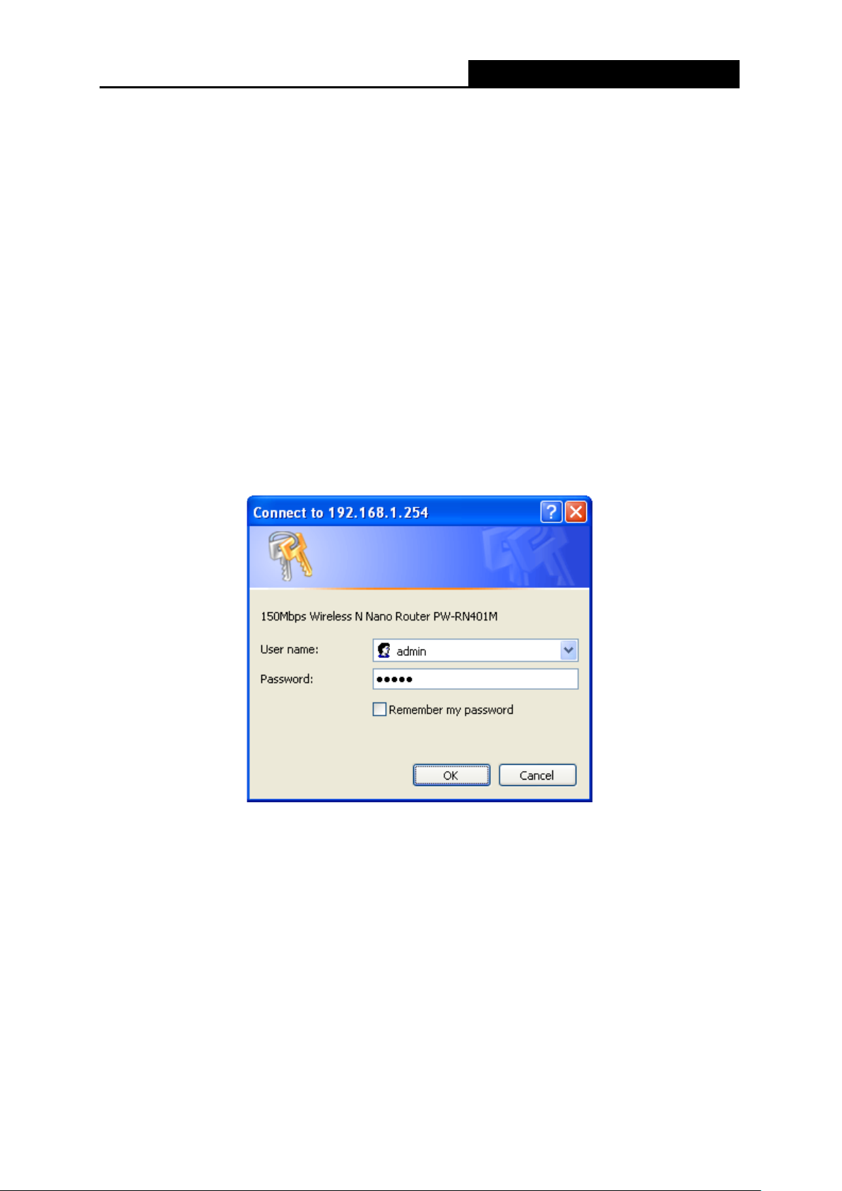
1. To access the configuration utility, open a web-browser and type in the default address
http://192.168.1.254 in the address field of the brow ser.
After a moment, a login window will appear, similar to the Figure 3-3. Enter admin for the
User Name and Password, both in lower case letters. Then click the OK button or press the
Enter key.
Note:
If the above screen does not pop-up, it means that y our Web-browser has been set to a proxy. Go
to Tools menu>Internet Options>Connections>LAN Settings, in the screen that appears, cancel
the Using Proxy checkbox , and cli ck OK to finish it.
Figure 3-3 Login Windows
- 13 -

PW-RN401M
150Mbps Wireless N Nano Router
2. After a successfully login, you can click the Quick Setup menu to quickly configure your
Router.
Figure 3-4 Quick Setup
3. Click Next, and then Working Mode page w il l app ear, shown in Figure 3-5.
Figure 3-5 Quick Setup - Working Mode
Note:
The Router supports five working modes for multi-user to access the Internet: AP, Router,
Repeater, Bridge and Client. In AP mode, PW-RN401M ena bles the wi red LAN to con nect to the
Internet wirelessly. In Rout er mod e, it can access the Internet via DSL/Cable Modem. In Re peat er
mode, the device will relay data to an associated root AP. In Bridge mode, the device bridges to
another AP. In Client mode, the device will act as a wireless station to enable wired host(s) to
access AP. You can configur e your device quickly by the following steps in different modes.
3.2.1 AP Mode
When you choose AP on Workin g Mode page i n Figure 3-5 , take the fol lowing steps:
1. Click Next in Figure 3-5, and then Wireless A P page will appear as shown in Figure 3-6.
- 14 -

PW-RN401M
150Mbps Wireless N Nano Router
Figure 3-6 Quick Setup - Wireless AP
Wireless Radio - Enable or disabl e t he wireless radio choosing fro m the pull-down list.
SSID - Enter a string of up to 32 characters. The same name of SSID (Service Set
Identification) must be assigned to all wireless devices in your network. The default
SSID is set to be Wireless_XXXXXX (XXXXXX indicates the last unique six numbers of
each Router’s MAC address). But it is recommended strongly that you change your
networks name (SSID) to a different value. This value is case-sensitive. For example,
TEST is NOT the same as test.
Region - Select your region fr o m the pull-down list. This f ield speci fies the r egion w her e
the wireless function of the Router can be used. It may be illegal to use the wireless
function of the Router in a region other than one of those specified in this field. If your
country or region is not listed, please contact your local government agency for
assistance.
Channel - This field determines which operating frequency will be used. The default
channel is set to Auto. It is not necessary to change the wireless channel unless you
notice interference problems with another nearby access point.
Mode - Select the desired mode. The default setting is 11bgn mixed.
• 11b only - Select if all of your wireless clients are 80 2. 11b.
• 11g only - Select if all of your wireless clients are 80 2. 11g.
• 11n only- Select only if all of your w irele ss cl ients are 802.11n.
• 11bg mixed - Select if you are using both 802.11b and 802.11g wireless clients.
- 15 -

PW-RN401M
150Mbps Wireless N Nano Router
• 11bgn mixed - Select if you are using a mix of 802.11b, 11g, and 11n w ireless clients.
Select the desired wireless mode. When 802.11g mode is selected, only 802.11g wireless
stations can connect to the Router. When 802.11n mode is selected, only 802.11n wireless
stations can connect to the AP. It is strongly recommended that you set the Mode to
802.11b/g/n, and all of 802.11b, 802.11g, and 802.11n wireless stations can connect to the
Router.
Channel Width - Select any channe l width from the pull-down list. The default setting is
automatic, which can auto matically ad just t he c hannel width for your clients.
Disable Security - The wireless security function can be enabled or disabled. If
disabled, the wireless stat ions w ill be ab le to c onn ect the Router without encryption. It is
recommended strongly that you choose one of following options to enable security.
WPA-PSK/WPA2-PSK - Select WPA based on pre -shared passphrase.
• PSK Password - You can enter ASCII or Hexadecimal characters. The default
password is the last unique eight numbers of each Router’s MAC address
For ASCII, the key can be made up of any numbers 0 to 9 and any letters A to Z, the
length should be between 8 and 63 characters.
For Hexadecimal, t he key can be ma de u p of any number s 0 to 9 and letters A to F,
the length should be between 8 and 64 characters.
Please also note the key i s case sensi tive, this means that upper and l ower case
keys will affect the outcome. It would also be a good idea to write down the key and
all related wireless security settings.
2. Click the Next button. You will then see the Finish page.
If you don’t make any change on the Wireless page, you will see the Finish page as shown
in Figure 3-7. Click the Finish button to finish the Quick Setup.
If there is something changed on the Wireless page, you will see the Finish page as shown
in Figure 3-8. Click the Reboot button to make your wireless configuration take eff ect and
finish the Quick Setup.
Figure 3-7 Quick Setup - Finish
- 16 -

PW-RN401M
150Mbps Wireless N Nano Router
Figure 3-8 Quick Setup – Finish
3.2.2 Router Mode
When you choose Router on Working Mode page in Figure 3-5 , t ake the follow ing steps:
1. Click Next in Figure 3-5, and you will see the following screen. The wireless settings on
Router mode are the same as t hat on AP mode.
2. Click Next in Figure 3-9, and then WAN Connection Type page will appear as shown in
Figure 3-10.
Figure 3-9 Quick Setup - Wireless Router
- 17 -

PW-RN401M
150Mbps Wireless N Nano Router
Figure 3-10 Quick Setup - WAN Connection Type
The Router supports three popular ways PPPoE, Dynamic IP and Sta tic IP to connect to the
Internet. To make sure the connection type your ISP provides, please refer to the ISP. Make s u re
the cable is securely plugged i nt o t he WAN port before detection.
PPPoE - For this connection, you will need your account name and passw or d from your ISP.
If you have applied ADSL to realize Dial-up service, you should choose this type. Under this
condition, you should fill in both the User Name and Password that the ISP supplied. Please
note that these fields are case-sensitive.
Figure 3-11 Quick Setup - PPPoE
Dynamic IP - Your ISP uses a DHCP service to assign your Router an IP address when
connecting to the Internet.
When the Router connects to a DHCP server, or the ISP supplies you with DHCP connection,
please choose this type. The Router gets the IP address automatically from the DHCP serv er
or the ISP if you choose Dynamic IP, and then the next screen will appear as shown in
Figure 3-16. Then you can go on w ith t he wireless configuration.
Static IP - T his type of connection uses a permanent, fixed (static) IP address that your ISP
assigned.
In this type, you should fill in the IP address, Subnet Mask, Default Gateway, and DNS IP
address manually, which are specified by your I SP.
- 18 -

PW-RN401M
150Mbps Wireless N Nano Router
Figure 3-12 Quick Setup - Static IP
3. Click Next, you will see the Finish page as shown in Figure 3-13. Click the Reboot button to
make your wireless config ur at ion take effect and finish the Quick Setup.
Figure 3-13 Quick Setup – Finish
3.2.3 Repeater Mode
When you choose Repeater Mode on Working Mode page in Figure 3-5 , take the following
steps:
1. Click Next, and then Wireless Repeater page wi ll appear as shown in Figure 3-14.
- 19 -

PW-RN401M
150Mbps Wireless N Nano Router
Figure 3-14 Quick Setup - Wireless Repeater
SSID - The SSID of AP that you want to access.
MAC of AP - The MAC address of AP that you want to access.
Region - Select your region from the pull-down list. This field specifies the region where the
wireless function of the Router can be used. It may be illegal to use the wireless function of
the Router in a region other than one of those specified in this field. If your count r y or region
is not listed, please contact your local govern m ent agency for assistance.
Survey - Click this button, you can search t he AP which runs in the environment.
Security Options - This option should be chosen according to the security configuration of
the AP y ou want to acces s . It is recommended that the sec urity ty pe is the same as y our AP’s
security type.
WEP Key Index - This opt ion should be c hosen if the key type is WEP (ASCI I) or WEP (HEX) .
It indicates the index of the WEP k ey.
Authentication Type - This option should be chosen if the key type is WEP (ASCII) or WEP
(HEX). It indicates the authenticat io n type of the Root AP.
Password - If the AP your router is going to connect need password, you need to fill the
password in this blan k.
Click Survey button on the Wireless page as shown in Figure 3-14, and then AP List page will
appear as shown in Figure 3-15. Find the SSID of the Access Point you want to access, and click
Connect in the corresponding row. For example, the third item is selected. The target network’s
SSID will be automatically filled into the corresponding box which is show n as the Figure 3-14.
- 20 -

PW-RN401M
150Mbps Wireless N Nano Router
Figure 3-15 AP List
Note:
If you know the SSID of the desir ed AP, you can also input it into the field "SSID" manually.
2. Click the Next button in Figure 3-14. Y ou wil l then see the Finish page.
Because something has changed on the Wireless Repeater page, you will see the Finish
page as shown in Figure 3-16. Click the Reboot button to make your wirel ess con figura tion
take effect and finish the Quick Setup.
Figure 3-16 Quick Setup - Finish
- 21 -

PW-RN401M
150Mbps Wireless N Nano Router
3.2.4 Bridge Mode
When you choose Bridge on Workin g Mode page i n Figure 3-5 , take the following steps:
1. Click Next, and then Wireless Repeater page wi ll appear as shown in Figure 3-17.
Figure 3-17 Quick Setup - Wireless Bridge
SSID - Enter a string of up to 32 characters. The same name of SSID (Service Set
Identification) must be assigned to all wireless devices in your network. The default SSID is
set to be Wireless_XXXXXX (XXXXXX indicates the last unique six numbers of each
Router’s MAC address). But it is recommended strongly that you change your networks
name (SSID) to a different value. This value is case-sensitive. For example, TEST is NOT
the same as test.
Region - Select your region from the pull-down list. This field specifies the region where the
wireles s f un c tion of the Router can be used. It may be illegal to use the wireless function of
the Router in a region other than one of those specified in this field. If your count r y or region
is not listed, please contact your local govern m ent agency for assistance.
Channel - This field determines which operating frequency will be used. It is not necessary
to change the wireless c h annel u nless you not ice in terferen ce pro ble ms with anot her nearby
access point. If you select auto, then AP will choose the best channel automatically.
Mode - Select the desired mode. The default setting is 11bgn mixed.
11b only - Select if all of y our w ireless clients are 802.11b.
- 22 -

PW-RN401M
150Mbps Wireless N Nano Router
11g only - Select if all of y our w ireless clients are 802.11g.
11n only- Select only if all of your wireless clients are 802.11n.
11bg mixed - Select if y ou ar e using both 802.11b and 802. 11g wireless clients.
11bgn mixed - Select if you are using a mix of 802.11b, 11g, and 11n wireless clients.
Select the desired wireless mode. When 802.11g mode is selected, only 802.11g wireless
stations can connect to the Router. When 802.11n mode is selected, only 802.11n wireless
stations can connect to the AP. It is strongly recommended that you set the Mode to
802.11b/g/n, and all of 802.11b, 802.11g, and 802.11n wireless stations can connect to the
Router.
Channel width - Select the channel width from the pull-down list. The defau lt setting is auto,
which can automatically adjust t he channel width for your clients.
Note:
If 11b only, 11g only, or 11bg mixed is selected in the Mode field, the Channel Width selecting
field will turn grey and the value w ill become 20MHz, w hich is u nable to be changed.
SSID (to be bridged) - The SSID of the AP your Router is going to connect to as a client.
You can also use the search funct ion to select the SSID to join.
BSSID (to be bridge d) - The BSSID of the AP your Router is going to connect to as a client.
You can also use the search funct ion to select the BSSID to join.
Survey - Click this button, you can survey t he AP w hich runs in the environment.
Security Options - This option should be chosen according to the AP's security
configuration. It is recommended that the security type is the same as your AP's security
type.
WEP Key Index - This option should be chosen if the key type is W EP (ASCII) or WEP
(HEX). It indicates the index of the WEP key.
Authentication Type - Th is opt ion shou ld be ch ose n if th e key ty pe is WEP (ASCII) or WEP
(HEX). It indicates the authorizat io n t ype of the Root AP.
PassWord - If the AP your Router is going to connect needs password, you need to fill the
password in this blank.
Click Survey button on the Wireless page as shown in Figure 3-17, and then AP List page will
appear as shown in Figure 3-18. Find the SSID of the Access Point you want to access, and click
Connect in the corresponding row. For example, the third item is selected. The target network’s
SSID will be automatically filled into the corresponding box which is show n as the Figure 3-17.
- 23 -

PW-RN401M
150Mbps Wireless N Nano Router
Figure 3-18 AP List
2. Click Next in Figure 3-17, and then Wireless Secur i ty Settings page will appear as shown
in Figure 3-19.
Figure 3-19 Quick Setup - Wireless Security Settings
This page is for setting w ireless secur ity of your own AP. When computers and mobile phones
are connected to the AP, they should input the same password.
- 24 -

PW-RN401M
150Mbps Wireless N Nano Router
Disable Security - The wireless security function can be enabled or disabled. If disabled,
the wireless stations will be able to connect the Router without encryption. It is
recommended strong ly t o enab le se c urit y.
PSK Passw ord - ou can enter ASCII or Hexadecimal characters. The default password is
the last unique eight number s of each Router’s MAC address
For ASCII, the key can be made up of any numbers 0 to 9 and any letters A to Z, the length
should be between 8 and 63 characters.
For Hexadecimal, the key can be made up of any numbers 0 to 9 and letters A to F, the
length should be between 8 and 64 characters.
Please also note the key is case sensitive, this means that upper and lower case keys will
affect the outcome. It would also b e a good idea to wr ite down the key and all related w ireless
security settings.
3. Click the Next button in Figure 3-20. You will then see the Finish page. Click the Reboot
button to make your wireless configuration take effect and finish the Q uick Setup.
Figure 3-20 Quick Setup - Finish
3.2.5 Client Mode
When you choose Client on W orki ng Mode page in Figure 3-5 , take the follow ing steps:
1. Click Next in Figure 3-5, and then Wireless Client page will appear as shown in Figure 3-21.
- 25 -

PW-RN401M
150Mbps Wireless N Nano Router
Figure 3-21 Quick Setup - Wireless Client
SSID - Enter the SSID that you want to access.
MAC of AP - Enter the MAC a ddr ess of AP that you want t o access .
Region - Select your region from the pull-down list. This field specifies the region where the
wireless function of the Router can be used. It may be illegal to use the wireless function of
the Router in a region other than one of those specified in thi s field. If your country or region
is not listed, please contact your local govern m ent agency for assistance.
Note:
Limited by the local law regulation s, version for North America does not hav e r egion selection
option.
Survey - Click this butt on, you can survey the AP which runs in the environment.
Security Options - This option should be chosen according to the security configuration of
the AP you want to access. It is recommended that t he security type is the same as your AP’s
security type.
WEP Key Index - This option should be chose n if the key ty pe is WEP (ASCII) or WEP (HEX).
It indicates the index of the WEP k ey.
Authentication Type - Th is opt ion should be chosen if the key type is WEP (ASCII) or WEP
(HEX). It indicates the authorizat io n t ype of the Root AP.
PassWord - If the AP your R outer is going to connect needs password, you need to fill the
password in this blank.
- 26 -

PW-RN401M
150Mbps Wireless N Nano Router
2. Click Survey button on the Wireless p age as sh ow n in Figure 3-21, and then AP L ist p a ge wi ll
appear as shown in Figure 3-22. Find the SSID of the Access Point you want to access, and
click Connect i n the corresponding row. For example, the third item is selected. The target
network’s SSID will be automatically filled into the corresponding box which is shown as the
Figure 3-21.
3. Click the Next button in Figure 3-23. You will then see the Finish page. Click the Reboot
button to make your wireless configuration take effect and finish the Quick Setup.
Figure 3-22 AP List
- 27 -

PW-RN401M
150Mbps Wireless N Nano Router
Figure 3-23 Quick Setup - Finish
Note:
1. The operating distance or range of your wireless connection varies significantly based on the
physical placement of the Rout er. For best results, place your Router.
Failure to follow these guidelines can result in significant performance degradation or inability to
wirelessly connect to the Router.
Near the center of the area in which your wireless stations will operat e.
In an elevated location such as a high shelf.
Away from the potential sources of interference, such as PCs, microwav es, and cordless
phones.
Away from large metal surfaces.
- 28 -

PW-RN401M
150Mbps Wireless N Nano Router
Chapter 4. Configuration for AP Mode
This chapter will show each Web page's key functions and the configuration way for AP Mode of
PW-RN401M.
4.1 Login
After your successful login, you can configure and manage the device. There are main menus on
the left of the web-based utility. Submenus will be available after you click on e of the ma in menus.
On the right, there are the corr es ponding explanations and instructions.
Figure 4-1
The detailed explan at io ns for each Web p age’s key function are listed below.
4.2 Status
The Status page provides the current status information about the Router on AP Mode. All
information is read-only.
- 29 -

PW-RN401M
150Mbps Wireless N Nano Router
Figure 4-2 Status
Firmware Version - The version information of the Rout er’s firmw are.
Hardware Version - The version information of the Router’s hardware.
LAN - This field displays the current settings or information for the LAN, you can configure
them in the Network > LAN page.
• MAC address - The physical addr ess of the Router, as seen from the LAN.
• IP address - The LAN IP address of the Router.
• Subnet Mask - The subnet mask associated with LAN IP address.
Wireless - This field displays basic information or status for wireless function, you can
configure them in the Wireless > Wireless Set t i ngs page.
• Wireless Mode - The current wireless wor king mode in us e.
• Wireless Radio - Indicates whether the wireless radio feature of the AP is enabled or
disabled.
• Name (SSID) - The SSID of the AP.
• Channel - The current w ireless channel in use.
• Mode - The current wireless mode which the Router w or ks o n.
- 30 -

PW-RN401M
150Mbps Wireless N Nano Router
• Channel Width - The curr ent w ireless channel width in use.
• MAC address - The physical address of the Router, as seen from the WLAN.
• WDS Status - The status of WDS connection.
System Up Time - The length of the tim e since the Router was last powered on or reset.
Click the Refresh but t on t o get the latest status and set t ings of the Router.
4.3 Quick Setup
Please refer to Section 3.2: "Quick Installation Guide."
4.4 Working Mode
The Router supports five operation mode types: AP, Router, Repeater, Bridge and Client.
Please select one your want. Clic k Save to save your choice, which is shown as Figure 4-3.
Figure 4-3 Wireless Working Mode Settings
AP - The wireless access point mo de.
Router - The wireless Router Mode. In this mode, the device enables multi-user to share
Internet via DSL/Cable Modem. The only wir ed por t works as WAN.
Repeater - The wireless Repeater Mode. It could extend the range o f wireless network.
Bridge - The wireless Bridge Mode. It could communicate with another wireless network.
Client - The Client Mode. The computer connected by Ethernet could get access to an AP by
Client mode.
Click OK in the following scr een and then the Router will reboot and to work on AP Mode.
- 31 -

PW-RN401M
150Mbps Wireless N Nano Router
Figure 4-4
4.5 Network
Figure 4-5 the Network menu
There is only one submenu under the Network menu (shown in Figure 4-5): LAN.
4.5.1 LAN
Choose menu “Network → LAN”, and then you can configure the IP parameters of the LAN on
the screen as below.
Figure 4-6 LAN
MAC Add re ss - The ph ysical ad dress of the LAN ports, as seen from the LAN. The value
can't be changed.
IP Address - Enter the IP address of your Router in dotted-decimal notation ( factor y default:
192.168.1.254).
Subnet Mask - An address code that determines the size of the network. Normally use
255.255.255.0 as the subnet ma sk.
Note:
1. If you change the IP Address of LAN, you must us e the new IP Address to login to the Router.
2. If the new LAN IP Address you set is not in the same subnet with the previous one, the IP
Address pool in the DHCP server will be configured automatically ,while the Vi rtual Serv er and
DMZ Host w ill not take effect un til they are re-configured.
- 32 -

PW-RN401M
150Mbps Wireless N Nano Router
4.6 Wireless
Figure 4-7 Wireless menu
There are five submenus under the Wireless menu (shown in Figure 4-7): Wireless Settings,
Wireless Security, MAC Filtering, Wireless Advanced and Wireless Statistics. Click an y of
them, and you will be able to configure the c or r esponding function.
4.6.1 Wireless Settings
Choose menu “Wireless → Wireless Settings”, and then you can configure the basic settings
for the wireless networ k on t his page.
SSID - Enter a string of up to 32 characters. The same name of SSID (Service Set
Identification) must be assigned to all wireless devices in your network. The default SSID is
set to be Wireless_XXXXXX (XXXXXX indicates the last unique six numbers of each
Router’s MAC address). But it is recommended strongly that you change your network’s
name (SSID) to a different value. This value is case-sensitive. For example, TEST is NOT
the same as test.
Figure 4-8 Wireless Settings - AP
- 33 -

PW-RN401M
150Mbps Wireless N Nano Router
Region - Select your region from the pull-down list. This field specifies the region where the
wireless function of the Router can be used. It may be illegal to use the wireless function of
the Router in a region other than one of those specified in this field. If your count r y or region
is not listed, please contact your local govern m ent agency for assistance.
Channel - This field determines w hich operati ng frequen cy w ill be used. The defau lt channel
is set to Auto. It is not necessary to change the wireless channel unless you notice
interference problems w it h anot her nearby access point.
Mode - Select the desired mode. The default setting is 11bgn mixed.
• 11b only - Select if all of your wireless clients are 80 2. 11b.
• 11g only - Select if all of your wireless clients are 80 2. 11g.
• 11n only- Select only if all of your w irele ss cl ients are 802.11n.
• 11bg mixed - Select if you are using both 802.11b and 802.11g w ireless clients.
• 11bgn mixed - Select if you are using a mix of 802.11b, 11g, and 11n w ireless clients.
Select the desired wireless mode. When 802.11g mode is selected, only 802.11g wireless
stations can connect to the Router. When 802.11n mode is selected, only 802.11n wireless
stations can connect to the AP. It is strongly recommended that you set the Mode to
802.11b/g/n, and all of 802.11b, 802.11g, and 802.11n wireless stations can connect to the
Router.
Channel Width - Select any channel width f rom the pull-down list. The default setting is
automatic, which can auto matically ad just t he c hannel width for your clients.
Enable Wireless Rout er Radio - The wireless radio of the Ro uter can be en abled or disable d
to allow wireless stations access. If enabled, the wireless stations will be able to access the
Router. Otherwise, wireless stations will not be able to access the Router.
Enable SSID Broadcast - If you select the Enable SSID Broad cast checkbox, the wireless
router will broadcast its name (SSID) on the air.
Enable WDS - You can select to enable WDS. With this fun ction, the Router ca n bridge tw o or
more WLANs. If this checkbox is selected, you will have to set the following parameters as
shown below. Make sure the following settings are correct .
- 34 -

PW-RN401M
150Mbps Wireless N Nano Router
SSID (to be bridged) - The SSID of the AP your Router is going to connect to as a client.
You can also use the search funct ion to select the SSID to join.
BSSID (to be bridge d) - The BSSID of the AP your Router is going to connect to as a client.
You can also use the search func t io n to select the BSSID to join.
Survey - Click this button, you can survey t he AP w hich runs in the current channel.
Security Options - This option should be chosen according to the AP's security
configuration. It is recommended that the security type is the same as your AP's security
type.
WEP Index - This option should be chosen if the key type is WEP (ASCII) or WEP (HEX). It
indicates the index of the WEP k ey.
Authentication Type - Th is opt ion shou ld be ch ose n if th e key ty pe is WEP (ASCII) or WEP
(HEX). It indicates the authorizat io n t ype of the Root AP.
Password - If the AP your Router is going to connect needs password, you need to fill the
password in this blank.
Be sure to click the Save button to save your settings on this page.
Note:
1. The operating distance or range of your wireless connection varies significantly based on the
physical placement of the Rout er. For best results, place your Router.
Near the center of the area in which your wireless stations will operat e.
In an elevated location such as a high shelf.
Away from the potential sources of interference, such as PCs, microwav es, and cordless
phones.
Away from large metal surfaces.
- 35 -

PW-RN401M
150Mbps Wireless N Nano Router
2. Failure to follow these guidelines can result in significant perf ormance degradation or inability
to wirelessly connect to the Router.
4.6.2 Wireless Security
Choose menu “Wireless → Wireless Security”, and then you can configure the security
settings of your wireless n etwork.
There are three wireless security modes supported by the Router: WEP (Wired Equivalent
Privacy), WPA/WPA2 and WPA-PSK/WPA2-PSK.
Disable Security - The wireless security function ca n be enab le d or disa bled. I f disabl ed, the
wireless stations will be able to connect the Router without encryption. But it’s strongly
recommended to choose one of the following modes to enable security.
WEP - It is based on the IEEE 802.11 standard.
• Type - you can choose the type for the WEP security on the pull-down list. The default
setting is Automatic, which can select
automatically based on the wireless station's capability and request.
Figure 4-9 Wireless Security
Shared Key or Open System authentication type
- 36 -

PW-RN401M
150Mbps Wireless N Nano Router
• WEP Key Format
format stands for any combination of hexadecimal digits (0-9, a-f, A-F) in the specified
length. ASCII format stands for any combination of keyboard characters in the specified
length.
• WEP Key (Password) - Select which of the four keys w ill be used and enter the matching
WEP key that you create. Make sure these valu es are identical on all wireless s t ations in
- Hexadecimal and ASCII formats are provided here. Hexadecimal
your network.
• Key Type - You can select the WEP key length (64-bit, or 128-bit, or 152-bit.) for
encryption. "Disabled" me ans t his WEP key ent r y is invalid.
64-bit - You can enter 10 hexadecimal digits (any combinat i on of 0-9, a-f, A-F, zero key is
not promoted) or 5 ASCII c har act er s.
128-bit - You can enter 26 hexade cimal d ig its (any combi nation of 0-9, a-f, A-F, zero key is
not promoted) or 13 ASCII characters.
152-bit - You can enter 32 hexade cimal d ig its (any combi nation of 0-9, a-f, A-F, zero key is
not promoted) or 16 ASCII characters.
Note:
If you do not set the key, the wireless security function is still disabled even if you have selected
Shared Key as Authentication Type.
WPA /WPA2
• Version - you can choose the version of the W PA securi ty from the pull-down list. The
default setting is Automatic, which can select
(WPA version 2) automat i cally based on the wireless st at ion' s capability and request.
WPA (Wi-Fi Protected Access) or WPA2
• Encryption - You can select Automatic, TKIP or AES.
• Radius Server IP - Enter the IP address of the Ra dius server.
• Radius Port - Enter the port that Radius server used.
• Radius Password - Enter t he password for the Radius server.
• Group Key Update Period - Specify the group key update interval in seconds. The value
should be 30 or above. En t er 0 t o disable the update.
WPA-PSK/WPA2-PSK- It’s the WPA/WPA2 authentication type based on pre-shared
passphrase.
• Version - you can choose the v er sion of the WPA-PSK security on the drop-down list. The
default setting is Automatic (Recommended), which can select
key of WPA) or WPA2-PSK (Pre-shared key of WPA) automatically based on the wireless
station's capability and r equest.
WPA-PSK (Pre-shared
- 37 -

PW-RN401M
150Mbps Wireless N Nano Router
• Encryption - When WPA-PSK or WPA is set as the Authentication Type, you can select
Automatic (Recommended), TKIP or AES as Encryption.
• PSK Password - You can enter ASCII or Hexadecimal characters. The default password
is the last unique eight numbers of each Router’s MAC address.
For ASCII, the key can be made up of any numbers 0 to 9 and any letters A to Z, the length
should be between 8 and 63 characters.
For Hexadecimal, the key can be made up of any numbers 0 to 9 and letters A to F, the
length should be between 8 and 64 characters.
Please also note the key is case sensitive, this means that upper and lower case keys will
affect the outcome. It would also be a good idea to write down the key and all related
wireless security settings.
• Group Key Update Period - Specify the group key update interval in seconds. The value
should be 30 or above. Ent er 0 t o disable the update.
Be sure to click the Save button to save your settings on this page.
4.6.3 MAC Filtering
Choose menu “Wireless → MAC Filterin g”, and then you can control the wireless access by
configuring the Wirel ess MA C Filtering funct ion, as shown in
Figure 4-10.
Figure 4-10 Wireless MAC Filtering
To filter wireless users by MAC Address, click Enable. The default setting is Disabled.
MAC Address - The wireless station's MAC address t hat you want to access.
Status - The status of this entry, either Enabled or Disabled.
Description - A simple description of the wireless station.
- 38 -

PW-RN401M
150Mbps Wireless N Nano Router
To Add a Wireless MAC A ddr ess filtering e nt r y, click the Add New… button. The "Add or Modi fy
Wireless MAC Address Filtering entry" page will appear, shown in Figure 4-11:
Figure 4-11 Add or Modify Wireless MAC Address Filtering entry
To add or modify a MAC Address Filtering entry, follow these inst ructions:
1. Enter the appropriate MAC Address into the MAC Address field. The format of the MAC
Address is XX-XX-XX-XX-XX-XX (X is any hexadecimal digit). For example:
00-0A-EB-B0-00-0B.
2. Give a simple description for the wireless station in the Description field. For example:
Wireless station A.
3. Select Enabled or Disabled for this entry on the Status pull-down list.
4. Click the Save button to save this entry.
To modify or delete an existing entry:
1. Click the Modify i n the entry you want to modify. If you want to delete the entry, click the
Delete.
2. Modify the information.
3. Click the Save button.
Click the Enable All button to make al l entr i es enabled
Click the Disabled All button to make all entries disabled.
Click the Delete All button to delete all entries.
Click the Next button to go to the next page.
Click the Previous button to retur n t o t he pr evious page.
For example: If you desire that the wireless station A with MAC address 00-0A-EB-B0-00-0B and
the wireless station B with MAC address 00-0A-EB-00-07-5F are able to access the Router, but all
the other wireless stations cannot access the Router, you can configure the Wireless MAC
Address Filtering list by following these steps:
1. Click the Enable button to enab le this function.
- 39 -

PW-RN401M
150Mbps Wireless N Nano Router
2. Select the radio button “Allow the stations specified by any enabled entries in the list to
access” for Filtering Rules.
3. Delete all or disable all entries if there are any entr ies already.
4. Click the
Add New... button.
• Enter the MAC address
• Enter wireless station A/B in the Description field.
• Select Enabled in the Status pull-down list.
• Click the Save button.
• Click the Back button.
00-0A-EB-B0-00-0B/00-0A-EB-00-07-5F
in the MAC Address field.
The filtering rules that con figur ed should be similar to the following list:
Figure 4-12 Filtering Rules
4.6.4 Wireless Advanced
Choose menu “Wireless → Wireless Advanced”, and then you can configure the advanced
settings of your wireless n etwork.
Figure 4-13 Wireless Advanced
- 40 -

PW-RN401M
150Mbps Wireless N Nano Router
T ra nsmit Pow er - Here you can specify the transmit power of Router. You can select High,
Middle or Low which you w ould like. High is t he default setting and is recommended.
B eacon Interval - Enter a value between 20-1000 milliseconds for Beacon Interval here.
The beacons are the packets sent by the Router to synchronize a wireless network. Beacon
Interval value determines the time interval of the beacons. The default value is 100.
R TS Threshold - Here you can specify the RTS (Request to Send) Threshold. If the packet
is larger than the specified RTS Threshold size, the Router will send RTS frames to a
particular receiving station and negotiate the sending of a data frame. The default value is
2346.
Fragmentation Threshold - This value is the maximum size determining whether packets
will be fragmented. Setting the Fragmentation Threshold too low may result in poor network
performance because of excessive packets. 2346 is the default setting and is
recommended.
DTIM Interval - This value deter mines t he interv al of the De livery Traf fic Indi cat ion Mes sage
(DTIM). A DTIM field is a c ountdow n f ield inf or ming c lients o f the ne xt window for listeni ng to
broadcast and multicast messages. When the Router has buffered broadcast or multicast
messages for associate d clients , it se nds th e ne xt DTIM with a DTIM I nterv al v alue. You can
specify the value between 1-255 Beacon Intervals. The default value is 1, which indicates
the DTIM Interval is the same a s Beacon Interval.
Enable W MM - WMM function c an guarantee the packets with high-priority messag es being
transmitted preferenti al ly. It is strongly recommended enabled.
E nable Short GI - This function is recommended f or it will increase the data capacity by
reducing the guard interv al time
Enabled AP Isolation - T his functio n isolate all connect ed wireless stations so that wireless
stations cannot access each other through WLAN. This function will be disabled if
WDS/Bridge is enabled.
Note:
If you are not familiar with the setting items in this page, it's strongly recommended to keep the
provided default values; ot her w ise it may result in l ower wireless network performance.
.
4.6.5 Wireless Statistics
Choose menu “Wireless → Wireless Statistics”, and then you can see the MAC Address,
Current S tatus, Received Packets and Sent Packets for each connected wireless station.
- 41 -

PW-RN401M
150Mbps Wireless N Nano Router
Figure 4-14 Wireless Statistics
MAC Address - Th e connected wireless station's MAC address
Current Status - The connected wireless station's running status, one of STA-AUTH /
STA-ASSOC / STA-JOINED / WPA / WPA-PSK / WPA2 / WPA2-PSK / AP-UP / AP-DOWN /
Disconnected
Receiv ed Packets - Packets receiv ed by the station
Sent Packet s - Packets sent by the station
You cannot change any of the values on this page. To update this page and to show the current
connected wireless stations, click on the Refresh button.
If the numbers of connected wirele ss stat ions go be y ond one page, cl ick the Next button to go to
the next page and click the Previous button t o r et ur n the previous page.
Note:
This page will be refreshe d aut omatically every 5 seconds.
4.7 DHCP
Figure 4-15 The DHCP menu
There are three submenus under the DHCP menu (shown in Figure 4-15), DHCP Settings,
DHCP Clients List and Address Reservation. Click any of them, and you will be able to
configure the corresponding function.
4.7.1 DHCP Settings
Choose menu “DHCP → DHCP Settings”, and then you can configure the DHCP Server on the
page as shown in
Figure 4-16. The Router is set up by default as a DHCP (Dynamic Host
- 42 -

PW-RN401M
150Mbps Wireless N Nano Router
Configuration Protocol) server, which provides the TCP/IP configuration for all the PC(s) that are
connected to the Router in the LAN.
Figure 4-16 DHCP Settings
DHCP Server - Enable or Disable the DHCP server. If you disable the Server, you must
have another DHCP server within your network or else you must configure the computer
manually.
Start IP Address - Specify an IP address for the DHCP Server to start with when assigning
IP addresses. 192.168.1.100 is the default start address.
End IP Address - Specify an IP address for the DH CP Server to end w it h when assign ing I P
addresses. 192.168.1.199 is the default end address.
Address Lease Time - The Address Lease Time is the amount of time a network user will
be allowed connection to the Router with their current dynamic IP Address. Enter the
amount of time in minutes and the user will be "leased" this dynamic IP Address. After the
time is up, the user will be automatically assigned a new dynamic IP address. The range of
the time is 1 ~ 2880 minutes. The default value is 120 minutes.
Default Gateway (Optional) - It is suggested to input the IP address of the LAN port of the
Router. The default value is 192.168.1.254.
Default Domain (Optional) - Input the domain name of your network.
Primary DNS - (Optional) Input the DNS IP address provided by your ISP or consult your
ISP.
Secondary DNS (Optional) - Input the IP address of another DNS server if your ISP
provides two DNS servers.
Note:
To use the DHCP server function of the Router, you must configure all com puters on the LAN as
"Obtain an IP Address autom atically".
- 43 -

PW-RN401M
150Mbps Wireless N Nano Router
4.7.2 DHCP Clients List
Choose menu “DHCP → DHCP Clients List”, and then you can view the information about the
clients attached to t he Rout er in the screen as shown in
Figure 4-17.
Figure 4-17 DHCP Clients List
Client Name - The name of the DHCP client
MAC Address - The MAC address of the DHCP client
Assigned IP - The IP addr ess t hat t he Router has allocated to the DHCP clie nt
Lease Time - The time of the DHCP client l eas ed. A fter the dy na mic I P addre s s has e xpir ed,
a new dynamic IP address will be aut omatically assigned to the user.
You cannot change any of the values on this page. To update this page and to show the current
attached devices, click th e Refresh button.
4.7.3 Address Reservation
Choose menu “DHCP → Address Reservation”, and then you can view and add a reserved
address for clients via the next screen (shown in
address for a PC on the LAN, that PC will always receive the same IP address each time when it
accesses the DHCP server. Reserved IP addresses should be assigned to the servers that
require permanent IP settings.
Figure 4-18 Address Reservation
MAC Address - Th e M AC address of the PC for which you want t o r eser ve an IP address.
Figure 4-18).When you specify a reserved IP
Reserved IP Address - The IP address reserved for the PC by the Rout er .
Status - The status of this entry either Enabled or Disabled.
To Reserve an IP address:
- 44 -

PW-RN401M
150Mbps Wireless N Nano Router
1. Click the Add New… button. Then Figure 4-19 will pop-up.
2. Enter the MAC address (in XX-XX-XX-XX-XX-XX format.) and IP address (in dotted-decimal
notation) of the co mputer for which you want to reserve an IP address .
3. Click the Save button.
Figure 4-19 Add or Modify an Address Reservation Entr y
To modify or de l e t e an existing entry:
1. Click the Modify i n the entry you want to modify. If you want to delete the entry, click the
Delete.
2. Modify the information.
3. Click the Save button.
Click the Enable/Disabled All button to make all entries enabled/disabled
Click the Delete All button to delete all entries.
Click the Next butt on t o go to the next page and Click the Previous button to ret ur n t he pr evious
page.
4.8 System Tools
Figure 4-20 The System Tool s menu
Choose menu “System Tools”, and then you can see the submenus under the main menu:
Diagnostic, Firmware, Factory Defaults, Backup & Restore, Reboot, Pa ssword, and System
- 45 -

PW-RN401M
150Mbps Wireless N Nano Router
Log. Click any of them, and you will be able to configure the corresponding function. T he detailed
explanations for each submenu are pr ovided below.
4.8.1 Diagnostic
Choose menu “System Tools → Diagnostic”, and then you can transact Ping or Traceroute
function to check connectivity of your network in the following screen.
Figure 4-21 Diagnostic Tools
Diagnostic Tool - Check the radio button to select one diagnostic t ool.
• Ping - This diagnostic tool troubleshoots connectivity, reachability, and name resolution to
a given host or gateway.
• Traceroute - This diagnost ic t ool tests the performance of a connection.
Note:
You can use ping/traceroute to test both numeric IP address or domain name. If
pinging/tracerouting the I P address is successful, but pinging/tracerouting t he d omain na me is not ,
you might have a name resolution problem. In this case, ensure that the domain name you are
specifying can be resolved by using Domain Name System (DNS) queries.
IP Address/Domain Name - Type the destination IP address (e.g.192.168.1254) or Domain
Pings Count - The number of Ping pac ket s f or a Ping connection. The default is 4.
Ping Packet Size - The size of Ping pa cket. The default is 64.
name
- 46 -

PW-RN401M
150Mbps Wireless N Nano Router
Ping Timeout - Set the waiting time for the reply of each Ping packet. If there is no reply in
the specified time, the connection is overtime. The default is 800.
Traceroute Max TTL - The max number of hops for a Traceroute connection. The default is
20.
Click Start to check the connectivity of the Internet.
The Diagnostic Results page displays the result of diag nosis.
If the result is similar to the following scree n, t he connectivity of the Internet is fine.
Figure 4-22 Diagnostic Results
Note:
Only one user can use this tool at one time. Options “Numbe r of Pings”, “Ping Size ” and “Ping
Timeout” are us ed for Ping function. Option “Tracert Hops” are used for Tracert function.
4.8.2 Firmware
Choose menu “System Tools → Firmware Upgrade”, and then you can update the latest
version of firmware for t he Router on the following screen.
Firmware Version - This display s t he cur r ent firmw ar e version.
Hardware Version - This displays the c urr ent hardware version. The hardware version of the
upgrade file must accord w it h t he Router’s current hardware version.
To upgrade the Router's firmware, follow these instructions below:
Figure 4-23 Firmware Upgrade
- 47 -

PW-RN401M
150Mbps Wireless N Nano Router
1. Download a more recent firmware upgrade file from our website.
2. Type the path and file name of the update file into the File field, or click the Browse button to
locate the update file.
3. Click the Upgrade button.
Note:
1. New firmware versions are posted at our website and can be downloaded for free. There is no
need to upgrade the firmware unless the new firmware has a new feature you want to use.
However, when experiencing problems caused by the Router rather than the configuration,
you can try to upgrade the firmwar e.
2. When you upgrade the Router's firmware, you may lose its current configurations, so before
upgrading the firmware please write down some of your customized settings to avoid losing
important settings.
3. Do not turn off the Router or press the Reset button while the f irmware is being upgraded,
otherwise, the Router may be damaged.
4. The Router will reboot after the upgrading has been finished.
4.8.3 Factory Defaults
Choose menu “System Tools → Factory Defaults”, and you can restore the configurations of
the Router to factory defaults on the fo llow ing scree n.
Figure 4-24 Restore Factory Default
Click the Restore button to reset all con fi gur ation settings to their default values.
• The default User Name: admin
• The default Password: admin
• The default IP Address: 192.168.1.254
• The default Subnet Mask: 255.255.255. 0
Note:
All changed settings will b e lost w hen defaults are restored.
- 48 -

PW-RN401M
150Mbps Wireless N Nano Router
4.8.4 Backup & Restore
Choose menu “System Tools → Backup & Restore”, and then you can save the current
configuration of the Router as a backup file and restore the configuration via a backup file as
shown in
To upgrade the Router's configuration, follow these instructions.
The current configurat ion will be covered by the upload ing configuration file. The upgrade process
Figure 4-25.
Figure 4-25 Backup & Restore Configuration
Click the Backup button to save all configuration settings as a backup file in your local
computer.
• Click the Browse… button to locate the update file for the Router, or enter the exact path
to the Setting file in the text box.
• Click the Restore button.
Note:
lasts for 20 seconds and the Router will restart automatically. Keep the Router on during the
upgrading process to prev ent any damage.
4.8.5 Reboot
Choose menu “System Tools → Reboot”, and then you can cli ck the Reboot button to reboot
the Router via the next screen.
Figure 4-26 Reboot the Router
Some settings of the Router will take effect only after rebooting, which include:
• Change the LAN IP Address (system will reboot automatically).
• Change the DHCP Settings.
• Change the Wireless configuratio ns .
- 49 -

PW-RN401M
150Mbps Wireless N Nano Router
• Change the Web Management Port.
• Upgrade the firmware of the Router (system will reboot automatically).
• Restore the Router's settings to fact or y defaults (system will reboot automatically).
• Update the configuration with the file (system will reboot automatically).
4.8.6 Password
Choose menu “System Tools → Password”, and then you can change the factory default user
name and password of the Rout er in the next screen as shown in
Figure 4-27 Password
It is strongly recommended that you should change the factory default user name and password
of the Router, because all users who try to access the Router's Web-based utility or Quick Setup
Figure 4-27.
will be prompted for the Rout er 's default user name and pass w or d.
Note:
The new user name and password must not exceed 14 characters in length and not include any
spaces. Enter the new Pa ssw or d twice to confirm.
Click the Save button when finished.
Click the Clear All button to clear all.
- 50 -

PW-RN401M
150Mbps Wireless N Nano Router
4.8.7 System Log
Choose menu “System T ools → System Log”, and then you can view the logs of the Rout er .
Figure 4-28 System Log
Refresh - Refresh the page to show the latest log list.
Clear All - All the logs will be delet ed from the Router permanently, not just from the page.
- 51 -

PW-RN401M
150Mbps Wireless N Nano Router
Chapter 5. Configuration for Router Mode
This chapter will show each Web page's key functions and the configurat ion way for Router Mode
of PW-RN401M.
5.1 Login
After your successful login, you can configure and manage the device. There are main menus on
the left of the web-based utility. Submenus will be available after you click on e of the ma in menus.
On the right, there are the corr es ponding explanations and instructions.
Figure 5-1
The detailed explan at io ns for each Web p age’s key function are listed below.
5.2 Status
The Status page provides the current status information about the Router on R outer Mode. All
information is read-only.
- 52 -

PW-RN401M
150Mbps Wireless N Nano Router
Firmware Version - The version information of the Rout er’s firmw are.
Hardware Version - The version information of the Router’s hardware.
LAN - This field displays the current settings or information for the LAN, you can configure
them in the Network > LAN page.
• MAC Address - The physical address of the Router, as seen from the LAN.
• IP Address - The LAN IP address of the Router.
• Subnet Mask - The subnet mask associated with LAN IP address.
Figure 5-2
- 53 -

PW-RN401M
150Mbps Wireless N Nano Router
Wireless - This field displays basic information or status for wireless function, you can
configure them in the Wireless > Wireless Set t i ngs page.
• Wireless Mode - The current wireless working mode in us e.
• Wireless Radio - Indicates whether the wireless radio feature of the AP is enabled or
disabled.
• Name (SSID) - The SSID of the AP.
• Channel - The current w ireless channel in use.
• Mode - The current wireless mode which the Router w or ks o n.
• Channel Width - The current w ireless channel width in use.
• MAC address - The physical address of the Router, as seen from the WLAN.
• WDS Status - The stat us of WDS conn ect ion.
WAN - This field displays the current settings or information for the WAN, you can configure
them in the Network > WAN page.
• MAC Address - The physical address o f the WAN port, as seen from the Internet.
• IP Address - The current WAN (Inter net) IP Address. This field will be blan k or 0.0.0. 0 if the
IP Address is assigned dynamically and there is no connection to the Internet.
• Subnet Mask - The subnet mask associ at ed with the WAN IP Address.
• Default Gateway - The Gateway currently used by the Router is shown here. When yo u
use Dynamic IP as the connection Internet type, the Renew button will be displayed here.
Click the Renew Button to obtain new IP parameters dynamically from the ISP. And if you
have got an IP address, Release button will be displayed here. Click the Release button to
release the IP address t he Router has obtained from the ISP.
DNS Server - The DN S (Domain Name System) server IP addresses currently used by the
Router.
Traf fic Statist i cs - The Router’s traffic st at i st ics.
• Sent (Bytes) - Traffic that counted in bytes has been sent out from the WAN port.
• Sent (Packets) - Traffic that counted in packets has been sent out from the WAN port.
• Received (Bytes) - T raf f ic t hat counted in byt es has been rece iv ed out fro m the WA N p ort.
• Received (Packets) - Traffic that counted in packets has been received out from the WAN
port.
System Up Time - The length of the tim e since the Router was last powered on or reset.
Click the Refresh but t on t o get the latest status and set t ings of the Router.
- 54 -

PW-RN401M
150Mbps Wireless N Nano Router
5.3 Quick Setup
Please refer to Section 3.2: "Quick Installation Guide."
5.4 Working Mode
The Router supports five operation mode types: AP, Router, Repeater, Bridge and Client.
Please select one your want. Clic k Save to save your choice, which is shown as Figure 5-3.
Figure 5-3 Wireless Working Mode Settings
AP - The wireless access point mo de.
Router - The wireless Router Mode. In this mode, the device enables multi-user to share
Internet via DSL/Cable Modem. The only wir ed por t works as WAN.
Repeater - The wireless Repeater Mode. It could extend the range of wireless network.
Bridge - The wireless Bridge Mode. It could communicate with another wireless network.
Client - The Client Mode. The computer connected by Ethernet could get access to an AP by
Client mode.
Click OK in the following scr een and then the Router will reboot and to work on Router Mode.
Figure 5-4
- 55 -

PW-RN401M
150Mbps Wireless N Nano Router
5.5 Network
Figure 5-5 the Network menu
There are three submenus under the Network menu (shown in Figure 5-5): WAN, LAN and MAC
Clone. Click any of them, and you will be ab le to configure the corresponding function.
5.5.1 WAN
Choose menu “Network → WAN”, and then you can configure the IP parameters of the WAN on
the screen below.
1. If your ISP provides t he DHCP service, please choose Dynamic IP type, and the Router will
automatically get IP parameter s fro m your ISP. You can see the page as follow (Figure 5-6):
This page displays the WAN IP parameters assigned dynamically by your ISP, including IP
address, Subnet Mask, Defa ult Gateway, etc. Click the Renew butt on t o r enew the IP parameters
from your ISP. Click the Release button to release the IP parameters.
Figure 5-6 WAN – Dynamic IP
- 56 -

PW-RN401M
150Mbps Wireless N Nano Router
MTU Size - The normal MTU (Maximum Transmission Unit) value for most Ethernet
networks is 1500 Bytes. It is not recommended that you change the default MTU Size
unless required by your I SP.
Use These DNS Servers - If your ISP gives you one or two DNS addresses, select Use
These DNS Servers and enter the primary and secondary addresses into the correct
fields. Otherwise, the DNS servers will be assigned dynamically from your I SP.
Note:
If you find error when you go to a website after entering the DNS addresses, it is likely that your
DNS servers are set up improperly. You should contact your ISP to get DNS server addr es ses.
Host Name - This option specifies the Host Name of the Router.
Get IP with Un icast DHCP - A few ISPs' DHCP servers do not support the broadcast
applications. If you cannot get the I P Address normally, y ou c an choose t his option. (It is
rarely required.)
Click the Save button to save your settings.
2. If your ISP provides a static or fixed IP Address, Subnet Mask, Gateway and DNS setting,
select Static IP. The Static IP settings page wil l app ear as shown in Figure 5-7.
Figure 5-7 WAN - Static IP
IP Address - Enter the IP addr ess in dotted-decimal notatio n provided by your ISP.
Subnet Mask - Enter the subnet Mask in dotted-decimal notation provided by your ISP,
usually is 255.255.255.0.
Default Gateway - (Optional) Enter the gateway IP address in dotted-decimal notation
provided by your ISP.
- 57 -

PW-RN401M
150Mbps Wireless N Nano Router
MTU Size - The normal MTU (Maximum Transmission Unit) value for most Ethernet
networks is 1500 Bytes. It is not recommended that you change the default MTU Size
unless required by your I SP.
Primary/Secondary DNS - (Optional) Enter one or two DNS addresses in
dotted-decimal not at ion provided by your ISP.
Click the Save button to save your settings.
3. If you r ISP provides a PPPoE connection, select PPPoE option. Then you should enter the
following paramet er s (Figure 5-8):
Figure 5-8 WAN – PPPoE
User Name/Password - Enter the User Name and Password provided by your ISP.
These fields are case-sensitive.
Confirm Password - Enter again the Password provided by your ISP to ensure the
password you entered i s correct.
Secondary Connection - It’s available only for PPPoE Connection. If y our I SP pr ovides
an extra Connection type such as Dynamic/Static IP to connect to a local area network,
then you can check the radio button of Dynamic/Static IP to activate this secondary
connection.
• Disabled - The Secondary Connection is disabled by default, so there is PPPoE
connection only. This is recommended.
- 58 -

PW-RN401M
150Mbps Wireless N Nano Router
• Dynamic IP - You can check this radio button to use Dynamic IP as the secondary
connection to connect to the local area network provided by ISP.
• Static IP - You can check this radio button to use Static IP as the secondary
connection to connect to t he loc al area network provided by ISP.
Connect on Demand - In this mode, the Internet connection can be terminated
automatically after a specified inactivity period (M ax Idle Time) and be re-established
when you attempt to access the Internet again. If you want your Internet connection
keeps active all the time, please enter “0” in the Max Id le Time field.
the number of minutes you want to have elapsed before your Internet access
disconnects.
Connect Automatically - The connection can be re-established automatically when it
was down.
Time-based Connecting - The connection will on ly be est ablish ed in the per iod from th e
start time to the end time (both are in HH:MM format).
Note:
Only when you have configured the system time on “System Tools → Time” page, will the
Time-based Connecting function can ta ke ef fect .
Connect Manually - You can click the Connect/Disconnect button to
connect/disconnect im mediately. This mode also support s the Max Idle Time function as
Connect on Dema nd mode. The Internet connection can be disco nnected aut omatic ally
after a specified inactivity period and re-established when you attempt to access the
Internet again.
Otherwise, enter
Click the Connect button to connect immediately. Click the Disconnect button to disconnect
immediately.
Caution: Sometimes the conne ction cann ot be terminated although you specif y a time to Max Idle
Time because some applications are visiting the Internet c ont i nually in the background.
If you want to do some advanced configurations, please click the Advanced button, and the page
shown in Figure 5-9 will then appear:
- 59 -

PW-RN401M
150Mbps Wireless N Nano Router
Figure 5-9 PPPoE Advanced Settings
MTU Size - The default MTU size is “1480” bytes, which is usually fine. It is not
recommended that y ou change t he default MTU Size unless required by your ISP.
Service Name/AC Name - The service name and AC (Access Concentrator) name
should not be configured unless you are sure it is necessary for your ISP.
In most cases,
leaving these fields blan k will work.
ISP Specified IP Address - If your ISP does not automatically assign IP addresses to
the Router during login, please click “Use IP address specified by ISP” check box and
enter the IP address provided by your ISP in dott ed-decimal notation.
Detect Online Interval - The Router will detect Access Concentrator online at every
interval. The defaul t value is “0”. You can input the value between “0” and “120”. The
value “0” means no detect .
Primary DNS/Secondary DNS - If your ISP does not automatically assign DNS
addresses to the Router during login, please click “Use the following DNS servers”
check box and enter the IP address in dotted-decimal notation of your ISP’s primary
DNS server. If a secondary DNS server address is available, enter it as well.
Click the Save button to save your settings.
4. If your ISP provides L2TP connection, please select L2TP option. Then you should enter the
following parameters (Figure 5-10):
- 60 -

PW-RN401M
150Mbps Wireless N Nano Router
Figure 5-10 WAN – L2TP
User Name/Password - Enter the User Name and Password provided by your ISP.
These fields are case-sensitive.
Dynamic IP/ Static IP - Choose either as you are given by your ISP. Click th e Connect
button to connect immediat ely. Click the Disconnect button to disconnect immediately.
Connect on Demand - You can configure the Router to disconnect from your Internet
connection after a specified period of inactivity (Max Idle Time). If your Internet
connection has been terminated due to inactivity, Connect on Demand enables the
Router to automatically re-establish your connection as soon as you attempt to access
the Internet again. If you wish to activate Connect on Demand, check the radio button.
If you want your Internet connection to remain active at all times, enter 0 in the Max Idle
Time field. Otherwise, enter the number of minutes you want to have elapsed before
your Internet connection terminates.
Connect Automatically - Connect automatically after the Router is disconn ected. To
use this option, check the r adio button.
Connect Manually - You can configure the Router to make it connect or disconnect
manually. After a specified period of inactivity (Max Idle Time), the Router will
disconnect from your Internet connection, and you will not be able to re-establish your
- 61 -

PW-RN401M
150Mbps Wireless N Nano Router
connection automatically as soon as you attempt to access the Internet again. To use
this option, check the radio button. If you want your Internet connection to remain active
at all times, enter "0" in the Max Idle Time field. Otherwise, ent er t he number of minutes
that you wish to have the Internet connecting last unless a new link is requested.
Caution: Sometimes the connection cannot be disconnected although you specify a time to Max
Idle Time, because some applicat io ns are v isiting the Int er net continually in the backgr ound.
Click the Save button to save your settings.
5. If you r ISP provides PPTP connection, please select PPTP option. And you should enter the
following p ar ameters (Figure 5-11):
User Name/Password - Enter the User Name and Password provided by your ISP.
These fields are case-sensitive.
Dynamic IP/ Static IP - Choose either as you are given by your ISP and enter the ISP’s
IP address or the do ma in name.
If you choose static IP and enter the domain name, you should also enter the DNS
assigned by your ISP. And click the Save button.
Figure 5-11 WAN – PPTP
- 62 -

PW-RN401M
150Mbps Wireless N Nano Router
Click the Connect button to connect immediately. Click the Disconnect button to
disconnect immediately.
Connect on Demand - You can configure the Router to disconnect from your Internet
connection after a specified period of inactivity (Max Idle Time). If your Internet
connection has been terminated due to inactivity, Connect on Demand enables the
Router to automatically re-establish your connection as soon as you attempt to access
the Internet again. If you wish to activate Connect on Demand, check the radio button.
If you want your Internet connection to remain active at all times, enter “0” in the Max
Idle Time field. Otherwise , enter t he number of min utes y ou want to hav e elaps ed before
your Internet connection terminates.
Connect Automatically - Connect automatically after the Router is disconn ected. To
use this option, check the r adio button.
Connect Manually - You can configure the Router to make it connect or disconnect
manually. After a specified period of inactivity (Max Idle Time), the Router will
disconnect from your Internet connection, and you will not be able to re-establish your
connection automatically as soon as you attempt to access the Internet again. To use
this option, click the radio but ton. If you want y our I nternet conn ect ion to re main activ e at
all times, enter "0" in the Max Idle Time field. Otherwise, enter the number in minutes
that you wish to have the Internet connecting last unless a new link is requested.
Caution: Sometimes the connection cannot be disconnected although you specify a time to Max
Idle Time because some applic at ions are visiting the Inter net cont inually in the background.
Click the Save button to save your settings.
5.5.2 LAN
Choose menu “Network → LAN”, and then you can configure the IP parameters of the LAN on
the screen as below.
MAC Add re ss - The ph ysical ad dress of the LAN ports, as seen from the LAN. The value
can't be changed.
IP Address - Enter the IP address of your Router in dotted-decimal notation ( factor y default:
192.168.1.254).
Figure 5-12 LAN
- 63 -

PW-RN401M
150Mbps Wireless N Nano Router
Subnet Mask - An address code that determines the size of the network. Normally use
255.255.255.0 as the subnet ma sk.
Note:
1. If you change the IP Address of LAN, you must use t he new I P Address to login to the Router.
2. If the new LAN IP Address you set is not in the sam e subnet with the previous one, th e IP
Address pool in the DHCP server will be configured automatically ,while the Virtual Server an d
DMZ Host w ill not take effect un til they are re-configured.
5.5.3 MAC Clone
Choose menu “Network → MAC Clone”, and then you can configure the WAN MAC address
on the screen below, as shown in
Some ISPs require that you register the MAC Address of your adapter. Changes are rarely
needed here.
WAN MAC Addre ss - This field displays the current MAC address of the WAN port. If your
ISP requires you to register the MAC address, please enter the correct MAC address into
this field in XX-XX-XX-XX-XX-XX format (X is any hexadecimal digit).
Your PC's MAC Address - This field displays the MAC address of the PC that is managing
the Router. If the MAC address is required, you can click the Clone MAC Address To
Figure 5-13:
Figure 5-13 MAC Address Clone
button and this MAC addr ess will fill in the WAN MAC Address field.
Click Restore Factory MAC to restore the MAC address of W AN port to the factory default
value.
Click the Save button to save your settings.
Note:
1. Only the PC on your LAN can use the MAC A ddress Clone function.
2. If you change WAN MAC Address when the WAN connection is PPPoE, it will not take effect
until the connection is re-established.
- 64 -

PW-RN401M
150Mbps Wireless N Nano Router
5.6 Wireless
Figure 5-14 Wireless menu
There are five submenus under the Wireless menu (shown in Figure 5-14): Wireless Settings,
Wireless Security, MAC Filtering, Wireless Advanced and Wireless Statistics. Click an y of
them, and you will be able to configure the c or r esponding function.
5.6.1 Wireless Settings
Choose menu “Wireless → Wireless Settings”, and then you can configure the basic settings
for the wireless networ k on t his page.
SSID - Enter a string of up to 32 characters. The same name of SSID (Service Set
Identification) must be assigned to all wireless devices in your network. The default SSID is
set to be Wireless_XXXXXX (XXXXXX indicates the last unique six numbers of each
Router’s MAC address). But it is recommended strongly that you change your networks
name (SSID) to a different value. This value is case-sensitive. For example, TEST is NOT
the same as test.
Figure 5-15 Wireless Settings - Router
- 65 -

PW-RN401M
150Mbps Wireless N Nano Router
Region - Select your region from the pull-down list. This field specifies the region where the
wireless function of the Router can be used. It may be illegal to use the wireless function of
the Router in a region other than one of those specified in this field. If your count r y or region
is not listed, please contact your local govern m ent agency for assistance.
Channel - This field determines which operating frequen cy will be used. The defau lt channel
is set to Auto. It is not necessary to change the wireless channel unless you notice
interference problems w it h anot her nearby access point.
Mode - Select the desired mode. The default setting is 11bgn mixed.
• 11b only - Select if all of your wireless clients are 80 2. 11b.
• 11g only - Select if all of your wireless clients are 80 2. 11g.
• 11n only- Select only if all of your w irele ss cl ients are 802.11n.
• 11bg mixed - Select if you are using both 802.11b and 802.11g w ireless clients.
• 11bgn mixed - Select if you are using a mix of 802.11b, 11g, and 11n w ireless clients.
Select the desired wireless mode. When 802.11g mode is selected, only 802.11g wireless
stations can connect to the Router. When 802.11n mode is selected, only 802.11n wireless
stations can connect to the AP. It is strongly recommended that you set the Mode to
802.11b/g/n, and all of 802.11b, 802.11g, and 802.11n wireless stations can connect to the
Router.
Channel Width - Select any channel width from the pull-down list. The default setting is
automatic, which can auto matically ad just t he c hannel width for your clients.
Enable Wireless Rout er Radio - The wireless radio of the Ro uter can be en abled or disable d
to allow wireless stations access. If enabled, the wireless stations will be able to access the
Router. Otherwise, wireless stations will not be able to access the Router.
Enable SSID Broadcast - If you select the Enable SSID Broad cast checkbox, the wireless
router will broadcast its name (SSID) on the air.
Enable WDS - You can select to enable WDS. With this fun ction, the Router ca n bridge tw o or
more WLANs. If this checkbox is selected, you will have to set the following parameters as
shown below. Make sure the following settings are correct .
- 66 -

PW-RN401M
150Mbps Wireless N Nano Router
SSID (to be bridged) - The SSID of the AP your Router is going to connect to as a client.
You can also use the search funct ion to select the SSID to join.
BSSID (to be bridge d) - The BSSID of the AP your Router is going to connect to as a client.
You can also use the search funct ion to select the BSSID to join.
Survey - Click this button, you can survey t he AP w hich runs in the current channel.
Security Options - This option should be chosen according to the AP's security
configuration. It is recommended that the security type is the same as your AP's security
type.
WEP Index - This option should be chosen if the key type is WEP (ASCII) or WEP (HEX). It
indicates the index of the WEP k ey.
Authentication Type - Th is opt ion shou ld be ch ose n if th e key ty pe is WEP (ASCII) or WEP
(HEX). It indicates the authorizat io n t ype of the Root AP.
Password - If the AP your Router is going to connect needs password, you need to fill the
password in this blank.
Be sure to click the Save button to save your settings on this page.
Note:
1. The operating distance or range of your wireless connection varies significantly based on the
physical placement of the Rout er. For best results, place your Router.
Near the center of the area in which your wireless stations will operate.
In an elevated location such as a high shelf.
Away from the potential sources of interference, such as PCs, microwav es, and cordless
phones.
Away from large metal surfaces.
2. Failure to follow these guidelines can result in significant perf ormance degradation or inability
to wirelessly connect to the Router.
- 67 -
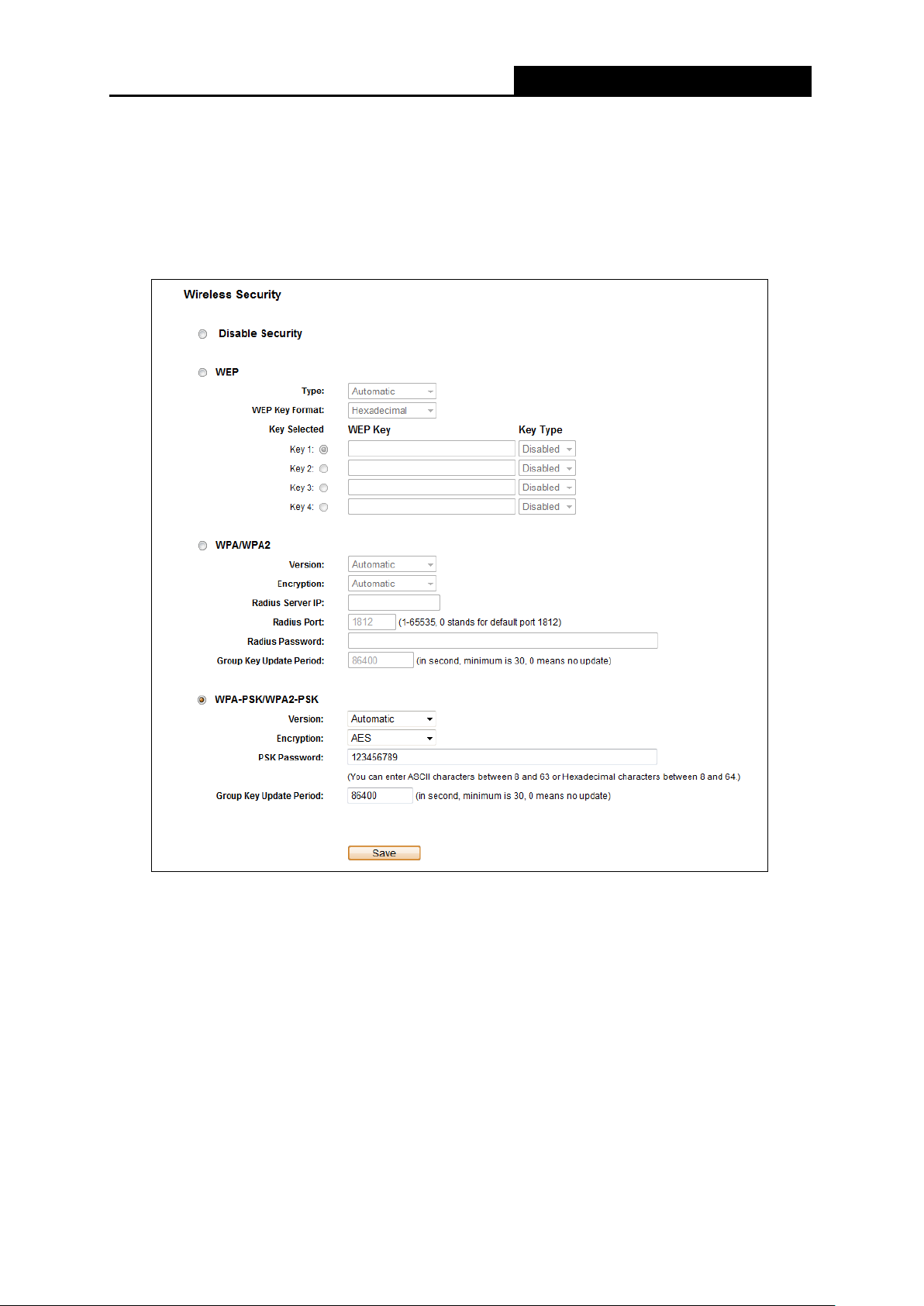
PW-RN401M
150Mbps Wireless N Nano Router
5.6.2 Wireless Security
Choose menu “Wireless → Wireless Security”, and then you can configure the security
settings of your wireless n etwork.
There are three wireless security modes supported by the Router: WEP (Wired Equivalent
Privacy), WPA/WPA2 and WPA-PSK/WPA2-PSK.
Disable Security - The wireless security function ca n be enab le d or disa bled. I f disabl ed, the
wireless stations will be able to connect the Router without encryption. But it’s strongly
recommended to choose one of the following modes to enable security.
WEP - It is based on the IEEE 802.11 standard.
• Type - you can choose the type for the WEP security on the pull-down list. The default
setting is Automatic, which can select
automatically based on the wireless station's capability and request.
• WEP Key Format
format stands for any combination of hexadecimal digits (0-9, a-f, A-F) in the specified
Figure 5-16 Wireless Security
Shared Key or Open System authentication type
- Hexadecimal and ASCII formats are provided here. Hexadecimal
- 68 -

PW-RN401M
150Mbps Wireless N Nano Router
length. ASCII format stands for any combination of keyboard characters in the specified
length.
• WEP Key (Password) - Select which of the four keys w ill be used and enter the matching
WEP key that you create. Make sure these valu es are identical on all wirele ss stations in
your network.
• Key Type - You can select the WEP key length (64-bit, or 128-bit, or 152-bit.) for
encryption. "Disabled" me ans t his WEP key ent r y is invalid.
64-bit - You can enter 10 hexadecimal digits (any combinat i on of 0-9, a-f, A-F, zero key is
not promoted) or 5 ASCII c har act er s.
128-bit - You can enter 26 hexade cimal d ig its (any combi nation of 0-9, a-f, A-F, zero key is
not promoted) or 13 ASCII characters.
152-bit - You can enter 32 hexade cimal d ig its (any combi nation of 0-9, a-f, A-F, zero key is
not promoted) or 16 ASCII characters.
Note:
If you do not set the key, the wireless security function is still disabled even if you have selected
Shared Key as Authentication Type.
WPA /WPA2
• Version - you can choose the version of the W PA security from the pull-down list. The
default setting is Automatic, which can select
(WPA version 2) automat i cally based on the wireless st at ion' s capability and request.
WPA (Wi-Fi Protected Access) or WPA2
• Encryption - You can select Automatic, TKIP or AES.
• Radius Server IP - Enter the IP address of the Ra dius server.
• Radius Port - Enter the port that Radius ser ver used.
• Radius Password - Enter t he password for the Radius server.
• Group Key Update Period - Specify the group key update interval in seconds. The value
should be 30 or above. En t er 0 t o disable the update.
WPA-PSK/WPA2-PSK- It’s the WPA/WPA2 authentication type based on pre-shared
passphrase.
• Version - you can choose the v er sion of the WPA-PSK security on the drop-down list. The
default setting is Automatic (Recommended), which can select
key of WPA) or WPA2-PSK (Pre-shared key of WPA) automatically based on the wireless
station's capability and r equest.
• Encryption - When WPA-PSK or WPA is set as the Authentication Type, you can select
Automatic (Recommended), TKIP or AES as Encryption.
WPA-PSK (Pre-shared
- 69 -

PW-RN401M
150Mbps Wireless N Nano Router
• PSK Password - You can enter ASCII or Hexadecimal characters. The default password
is the last unique eight numbers of each Router’s MAC address
For ASCII, the key can be made up of any numbers 0 to 9 and any letters A to Z, the length
should be between 8 and 63 characters.
For Hexadecimal, the key can be made up of any numbers 0 to 9 and letters A to F, the
length should be between 8 and 64 characters.
Please also note the key is case sensitive, this means that upper and lower case keys will
affect the outcome. It would also b e a good idea to wr ite down the key and all related w ireless
security settings.
• Group Key Update Period - Specify the group key update interval in seconds. The value
should be 30 or above. En t er 0 t o disable the update.
Be sure to click the Save button to save your settings on this page.
5.6.3 MAC Filtering
Choose menu “Wireless → MAC Filterin g”, and then you can control the wireless access by
configuring the Wireless MAC Filtering function, as shown in
Figure 5-17.
To filter wireless users by MAC Address, click Enable. The default setting is Disabled.
MAC Address - The wireless station's MAC address t hat you want to access.
Status - The status of this entry, either Enabled or Disabled.
Description - A simple description of the wir eless station.
To Add a Wireless MAC A ddr ess filtering e nt r y, click the Add New… button. The "A dd or Modi fy
Wireless MAC Address Filtering entry" page will appear, shown in Figure 5-18:
Figure 5-17 Wireless MAC Filtering
- 70 -

PW-RN401M
150Mbps Wireless N Nano Router
Figure 5-18 Add or Modify Wireless MAC Address Filtering entry
To add or modify a MAC Address Filtering entry, follow these inst ructions:
1. Enter the appropriate MAC Address into the MAC Address field. The format of the MAC
Address is XX-XX-XX-XX-XX-XX (X is any hexadecimal digit). For example:
00-0A-EB-B0-00-0B.
2. Give a simple description for the wireless station in the Description field. For example:
Wireless station A.
3. Select Enabled or Disabled for this entry on the Status pull-down list.
4. Click the Save button to save this entry.
To modify or delete an existing entry:
1. Click the Modify i n the entry you want to modify. If you want to delete the entry, click the
Delete.
2. Modify the information.
3. Click the Save button.
Click the Enable All button to make al l entr ies enabled
Click the Disabled All button to make all entries disabled.
Click the Delete All button to delete all entries.
Click the Next button to go to the next page.
Click the Previous button to retur n t o t he pr evious page.
For example: If you desire that the wireless station A with MAC address 00-0A-EB-B0-00-0B and
the wireless station B with MAC address 00-0A-EB-00-07-5F are able to access the Router, but all
the other wireless stations cannot access the Router, you can configure the Wireless MAC
Address Filtering list by following these steps:
1. Click the Enable button to enab le this function.
2. Select the radio button “Allow the stations specified by any enabled entries in the list to
access” for Filtering Rules.
- 71 -
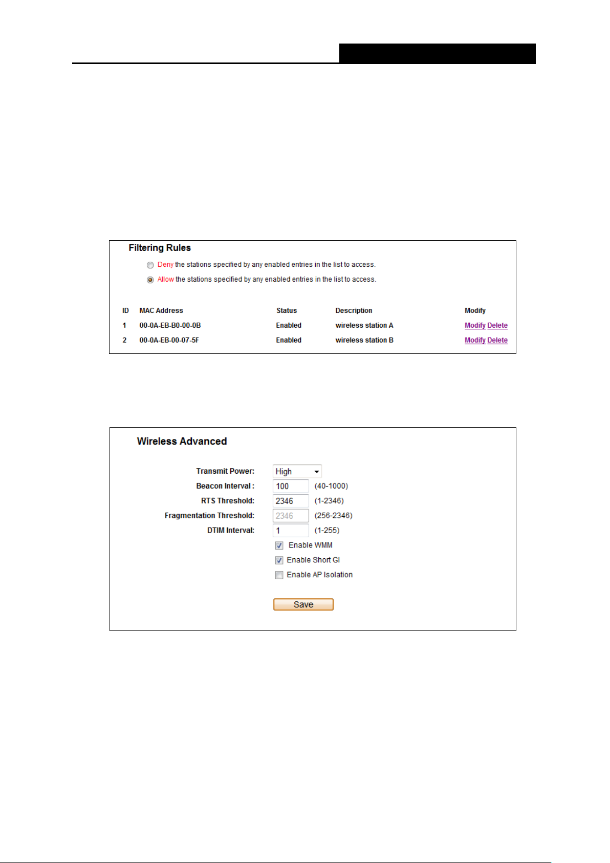
PW-RN401M
150Mbps Wireless N Nano Router
3. Delete all or disable a l l entries if there are any entries already.
4. Click the
Add New... button.
1) Enter the MAC address
2) Enter wireless station A/B in the Description field.
3) Select Enabled in the Status pull-down list.
4) Click the Save button.
5) Click the Back button.
The filtering rules that con figur ed should be similar to the following list:
00-0A-EB-B0-00-0B/00-0A-EB-00-07-5F
in the MAC Address field.
5.6.4 Wireless Advanced
Choose menu “Wireless → Wireless Advanced”, and then you can configure the advanced
settings of your wireless n etwork.
T ra nsmit Pow er - Here you can specify the transmit power of Router. You can select High,
Middle or Low which you w ould like. High is t he default setting and is recommended.
B eacon Interval - Enter a value between 20-1000 milliseconds for Beacon Interval here.
The beacons are the packets sent by the Router to synchronize a wireless network. Beacon
Interval value determines the time interval of the beacons. The default value is 100.
Figure 5-19 Wireless Advanced
- 72 -

PW-RN401M
150Mbps Wireless N Nano Router
R TS Threshold - Here you can specify the RTS (Request to Send) Threshold. If the packet
is larger than the specified RTS Threshold size, the Router will send RTS frames to a
particular receiving station and negotiate the sending of a data frame. The default value is
2346.
Fragmentation Threshold - This value is the maximum size determining whether packets
will be fragmented. Setting the Fragmentation Threshold too low may result in poor network
performance because of excessive packets. 2346 is the default setting and is
recommended.
DTIM Interval - This value deter mines t he interv al of the De livery Traf fic Indi cat ion Mes sage
(DTIM). A DTIM field is a countdown field infor ming c lient s of t he next wind ow f or liste ning t o
broadcast and multicast messages. When the Router has buffered broadcast or multicast
messages for associate d clients , it se nds th e ne xt DTIM with a DTIM I nterv al v alue. You can
specify the value between 1-255 Beacon Intervals. The default value is 1, which indicates
the DTIM Interval is the same a s Beacon Interval.
Enable W MM - WMM function c an guarantee the packets with high-priority messag es being
transmitted preferenti al ly. It is strongly recommended enabled.
E nable Short GI - This function is recommended f or it will increase the data capacity by
reducing the guard interv al time
Enabled AP Isolation - T his function isolate all connected wireless stations so that wireless
stations cannot access each other through WLAN. This function will be disabled if
WDS/Bridge is enabled.
Note:
If you are not familiar with the setting items in this page, it's strongly recommended to keep the
provided default values; ot her w ise it may result in l ower wireless network performance.
.
5.6.5 Wireless Statistics
Choose menu “Wireless → Wireless Statistics”, and then you can see the MAC Address,
Current S tatus, Received Packets and Sent Packets for each connected wireless station.
Figure 5-20 Wireless Statistics
- 73 -

PW-RN401M
150Mbps Wireless N Nano Router
MAC Address - The connected wireless station's MAC address
Current Status - The connected wireless station's running status, one of STA-AUTH /
STA-ASSOC / STA-JOINED / WPA / WPA-PSK / WPA2 / WPA2-PSK / AP-UP / AP-DOWN /
Disconnected
Receiv ed Packets - Packets receiv ed by the station
Sent Packet s - Packets sent by t he st ation
You cannot change any of the values on this page. To update this page and to show the current
connected wireless stations, click on the Refresh button.
If the numbers of connected wirele ss stat ions go be y ond one page, cl ick the Next button to go to
the next page and click the Previous button t o r et ur n the previous page.
Note:
This page will be refreshe d aut omatically every 5 seconds.
5.7 DHCP
Figure 5-21 The DHCP menu
There are three submenus under the DHCP menu (shown in ), DHCP Settings , DHCP Clients
List and Address Reservation. Click any of them, and you will be able to configure the
corresponding function.
5.7.1 DHCP Settings
Choose menu “DHCP → DHCP Setting s”, and then you can configure the DHCP Server on the
page as shown in
Configuration Protocol) server, which provides the TCP/IP configuration for all the PC(s) that are
connected to the Router on the LAN.
Figure 5-22. The Router is set up by default as a DHCP (Dynamic Host
- 74 -

PW-RN401M
150Mbps Wireless N Nano Router
Figure 5-22 DHCP Settings
DHCP Server - Enable or Disable the DHCP server. If you disable the Server, you must
have another DHCP server within your network or else you must configure the computer
manually.
Start IP Address - Specify an IP address for the DHCP Server to start with when assigning
IP addresses. 192.168.1.100 is the default start address.
End IP Address - Specify an IP address for the DH CP Server to end w it h when assign ing I P
addresses. 192.168.1.199 is the default end address.
Address Lease Time - The Address Lease Time is the amount of time a network user will
be allowed connection to the Router with their current dynamic IP Address. Enter the
amount of time in minutes and the user will be "leased" this dynamic IP Address. After the
time is up, the user will be automatically assigned a new dynamic IP address. The range of
the time is 1 ~ 2880 minutes. The default value is 120 minutes.
Default Gateway (Optional) - It i s suggested to input the IP address of the LAN port of the
Router. The default value is 192.168.1.254.
Default Domain (Optional) - Input the domain name of your network.
Primary DNS - (Optional) Input the DNS IP address provided by your ISP or consult your
ISP. Or consult your ISP.
Secondary DNS (Optional) - Input the IP address of another DNS server if your ISP
provides two DNS servers.
Note:
To use the DHCP server function of the Router, you must configure all com puters on the LAN as
"Obtain an IP Address autom at ically".
- 75 -

PW-RN401M
150Mbps Wireless N Nano Router
5.7.2 DHCP Clients List
Choose menu “DHCP → DHCP Clients List”, and then you can view the information about the
clients attached to t he Rout er in the screen as shown in
Figure 5-23.
Figure 5-23 DHCP Clients List
Client Name - The name of the DHCP client
MAC Address - The MAC address of the DHCP client
Assigned IP - The IP addr ess t hat the Router has allocated to t he DHCP clie nt
Lease Time - The time of the DHCP client l eas ed. A fter the dy na mic I P addre s s has e xpir ed,
a new dynamic IP address will be aut omatically assigned to the user.
You cannot change any of the values on this page. To update this page and to show the current
attached devices, click th e Refresh button.
5.7.3 Address Reservation
Choose menu “DHCP → Address Reservation”, and then you can view and add a reserved
address for clients via the next screen (shown in
address for a PC on the LAN, that PC will always receive the same IP address each time when it
accesses the DHCP server. Reserved IP addresses should be assigned to the servers that
require permanent IP settings.
Figure 5-24 Address Reservation
MAC Address - Th e M AC address of the PC for which you want t o r eser ve an IP address.
Reserved IP Address - The IP address reserved for the PC by the Rout er .
Figure 5-24).When you specify a reserved IP
Status - The status of this entry , either Enabled or Disabled.
- 76 -

PW-RN401M
150Mbps Wireless N Nano Router
To Reserve an IP address:
1. Click the Add New… button. Then will pop-up.
2. Enter the MAC address (in XX-XX-XX-XX-XX-XX format.) and IP address (in dotted-decimal
notation) of the co mputer for which you want to r eserve an IP address.
3. Click the Save button.
Figure 5-25 Add or Modify an Address Reservation En tr y
To modify or de l e t e an existing entry:
1. Click the Modify i n the entry you want to modify. If yo u want to delete the entry, click the
Delete.
2. Modify the information.
3. Click the Save button.
Click the Enable/Disabled All button to make all entries enabled/disabled.
Click the Delete All button to delete all entries.
Click the Next butt on t o go to the next page and Click the Previous button to ret ur n t he pr evious
page.
5.8 Forwarding
Figure 5-26 The Forwarding menu
There are four submenus under the Forwarding menu (shown in Figure 5-26): Virtual Servers,
Port Triggering, DMZ and UPnP. Click any of them, and you will be able to configure the
corresponding function.
- 77 -

PW-RN401M
150Mbps Wireless N Nano Router
5.8.1 Virtual Servers
Choose menu “Forwarding → Virtual Servers”, and then you can view and add virtual servers
in the screen as shown in
Figure 5-27. Virtual servers can be used f or setting up public services
on your LAN, such as DNS, Email and FTP. A virtual server is defined as a service port, and all
requests from the Internet to this service port will be redirected to the computer specified by the
server IP. Any PC that was used for a virtual server must have a static or reserved IP Address
because its IP Address may be changed when u si ng the DHCP function.
Figure 5-27 Virtual Servers
Service Port - The numbers of External Ports. You can type a service port or a range of
service ports (in XXX – YYY format, XXX is the start port number, YYY is the end port
number).
IP Address - The IP Address of the PC providing the service application.
Protocol - The protocol used for this application, either TCP, UDP, or All (all protocols
supported by the Router).
Status - The status of this entry, either Enabled or Disabled.
To setup a virtual server entry:
1. Click the Add New… button, the next screen will pop-up as shown in Figure 5-28.
2. Select the service port y ou want to use fro m the Co mmon Service Port list. If the Common
Service Port list does not have the service that you want to use, type the service port
number or service port range i n the Service Port box.
3. Type the IP Address of the computer in the IP Address box.
4. Select the protocol used for this appl icat i on, either TCP, UDP, or All.
5. Select the Enable to enable the v ir t ual server.
6. Click the Save button.
- 78 -

PW-RN401M
150Mbps Wireless N Nano Router
→
Figure 5-28 Add or Modify a Virtual Server Entry
Note:
If your computer or server has more than one type of available service, please select another
service, and enter the same IP Address for that comput er or ser ver.
To modify or de l e t e an existing entry:
1. Click the Modify i n the entry you want to modify. If you want to delete the entry, click the
Delete.
2. Modify the information.
3. Click the Save button.
Click the Enable/Disabled All button to make all entries enabled/disabled.
Click the Delete All button to delete all entries.
Click t he Next button to go to the next page and click the Previous button to return the previous
page.
Note:
If you set the service port of the virtual server as 80, you must set the W eb management port on
“Security
Otherwise there will be a conflict to disable the virtual server.
Remote Management” page to be any other value except 80 such as 8080.
5.8.2 Port Triggering
Choose menu “Forwarding → Port Triggering”, and then you can view and add port triggering
in the screen as shown in
Figure 5-29. Some applications require multiple connections, like
Internet games, video conferencing, Internet calling and so on. These applications cannot work
with a pure NAT Router. Port Triggering is used for some of these applications that can work with
an NAT Router.
- 79 -

PW-RN401M
150Mbps Wireless N Nano Router
Figure 5-29 Port Triggering
Once the Router is configured, the operat ion is as follows:
1. A local host makes an outgoing connection using a destination port number defined in the
Trigger Port fi eld.
2. The Router records this connection, opens the incoming port or ports associated with this
entry in the Port Triggering table, and associates th em with the local host.
3. When necessary, the external host will be ab le to c onnect to t he local h ost using one of th e
ports defined in the Incoming Ports field.
Trigger Port - The port for out going t raffic. An outgoing connect ion using t his p ort will trigger
this rule.
Trigger Protocol - The protocol used for Trigger Ports, either TCP, UDP, or All (all
protocols supported by the Router).
Incoming Ports Range - The port or port range used by the remote system when it
responds to the outgoing request. A response using one of these ports will be forwarded to
the PC that triggered this rule. You can input at most 5 groups of ports (or port sections).
Every group of ports must be set apart with ",". For example, 2000-2038, 2050-2051, 2085,
3010-3030.
Incoming Protocol - The protocol used for Incoming Ports Range, either TCP or UDP, or
ALL (all protocols supported by the Router).
Status - The status of this entry, either Enabled or Disabled.
To add a new rule, f ol l ow the steps below:
1. Click the Add New… button, the next screen will pop-up as shown in Figure 5-30.
2. Select a common application from the Common Applications drop-down list, then the
Trigger Port field and the Incoming Ports field will be automatically filled. If the Common
Applications do not have the application you need, enter the Trigger Port and the
Incoming Ports manually.
3. Select the protocol used for Tri gger Port from the Trigger Protocol drop-down list, either
TCP, UDP, or All.
4. Select the protocol used for Incoming Ports f rom the Incoming Protocol drop-down list,
either TCP or UDP, or All.
- 80 -

PW-RN401M
150Mbps Wireless N Nano Router
5. Select Enable in Status field.
6. Click the Save button to save the new rule.
Figure 5-30 Add or Modify a Port Tr iggeri ng Entry
To modify or delete an existing entry:
1. Click the Modify in the entry you want to modify. If you want to delete the entry, click the
Delete.
2. Modify the information.
3. Click the Save button.
Click the Enable All button to make al l entr i es enabled.
Click the Disabled All button to make all entries disabled.
Click the Delete All button to delete a ll entries.
Note:
1. When the trigger connection is relea sed, the corresponding opening ports will be closed.
2. Each rule is allowed to be used only by one host on LAN synchronously. The trigger
3. Incoming Port Range cannot ov erlap each other.
connection of other host s on LAN will be refused.
5.8.3 DMZ
Choose menu “Forwarding → DMZ”, and then you can view and configure DMZ host in the
screen as shown in
Figure 5-31. The DMZ host feature allows one local host to be exposed to the
Internet for a special-purpose service such as Internet gaming or videoconferencing. DMZ host
forwards all the ports at the same time. Any PC whose port is being forwarded must have its
DHCP client funct ion d isabled and should have a new static IP Address assigned to it because its
IP Address may be changed when using the DHCP function.
- 81 -
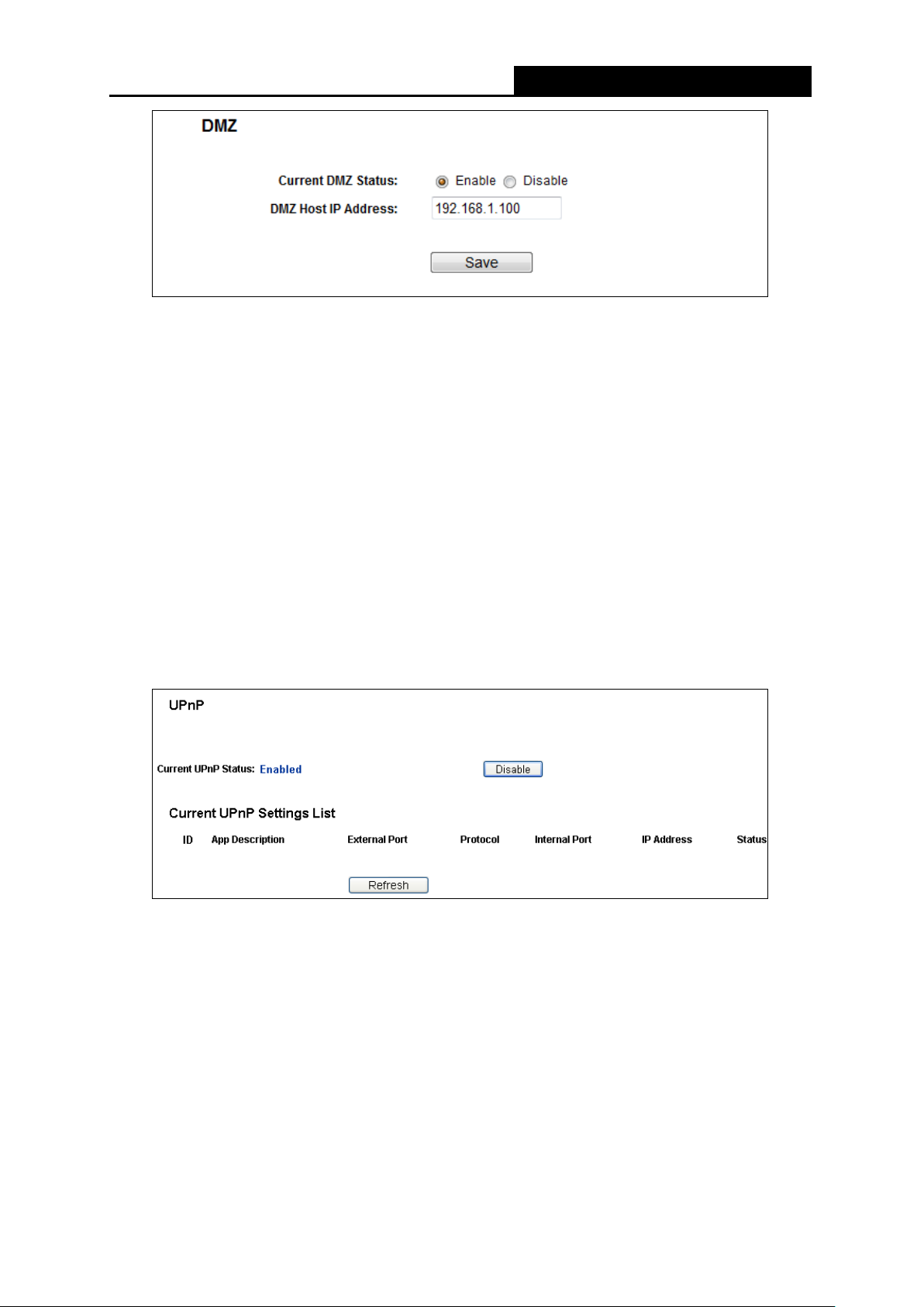
PW-RN401M
150Mbps Wireless N Nano Router
Figure 5-31 DMZ
To assign a computer or server to be a DMZ server:
1. Check the Enable radio button.
2. Enter the IP Address of a local host in the D MZ Host IP Address field.
3. Click the Save button.
Note:
After you set the DMZ host, the firewall related to the host w il l not w ork.
5.8.4 UPnP
Choose menu “Forwarding → UPnP”, and then you can view the information about UPnP
(Universal Plug and Play) in the screen as shown in
devices, such as Internet computers, to access the local host resources or devices as needed.
UPnP devices can be automatically discovered by the UPnP serv ice application on the LAN.
Figure 5-32 UPnP
Current UPnP Status - UPnP can be enabled or disabl ed by clic king t he Enable or Disable
button.
Current UPnP Settings List - This table displays the current UPnP information.
Figure 5-32. The UPnP feature allows the
• App Description - Th e description provided by the application in the UPnP request.
• External Port - The external port t he Rout er opens for the application.
• Protocol - The type of protocol the Router opens for the application.
• Internal Port - The Internal port the Router opens for local host.
• IP Address - The IP address of the UPnP device that is currently accessing the Rout er.
- 82 -

PW-RN401M
150Mbps Wireless N Nano Router
• Status - The status of the port is displayed here. “Enabled” means that the port is still
active. Otherwise, the port is inactiv e.
Click Refresh to update the Current UPnP Settings List.
5.9 Security
Figure 5-33 The Security menu
There are six submenus under the Security menu as shown in Figure 5-33: Firewall, IP Address
Filtering, Domain Filtering, MAC Address Filtering, Remote Management, and Advanced
Security. Click any of them, and you wi ll be able to configure the corresponding function.
5.9.1 Firewall
Using the Firewall page, you can turn the general firewall switch on or off. The default setting for
the switch is off. If the gen er al firewall switch is off, even if IP Address Filtering, DN S Filt er i ng and
MAC Filtering are enabled , t heir settings are ineffective.
Figure 5-34 Firewall Settings
- 83 -

PW-RN401M
150Mbps Wireless N Nano Router
Enable Firewall - the general firewall switch is on or of f.
Enable IP Address Filtering - set IP Address Filtering is enabled or disabled. There are two
default filtering rules of IP Address Filtering, either Allow or Deny passing through the router.
Enable Domain Filtering - set Domain Filtering is enabled or disabled.
Enable MAC Filtering - set MA C Address Filtering is enabled or disabl ed. You can select the
default filtering rules of MAC Address Filtering, either Allow or Deny accessing the router.
5.9.2 IP Address Filtering
The IP address Filtering feature allows you to control Internet Access by specific users on your
LAN based on their IP addresses. The IP address filtering is set on this page:
Figure 5-35 IP address Filtering
To disable the IP Address Filtering feature, keep the default setting, Disabled. To set up an IP
Address Filtering entry, click Enable Firewall and Enable IP Address Filtering on the Firewall
page, and click t he Add New… button. The page "A dd or Modif y an IP A ddress Filtering entry"
will appear shown in Figure 5-36:
Figure 5-36 Add or Modify an IP Address Filtering Entry
- 84 -

PW-RN401M
150Mbps Wireless N Nano Router
To create or modify an IP Address Filtering entry, please follow these instructions:
1. Effective Time - Enter a range of time in HHMM format, which point to the range time for t he
entry to take ef fect. For example, 0803 - 1705, the entry will take effect fro m 0 8: 03 to 17:05.
2. LAN IP Address - Enter a LAN IP Address or a range of LAN IP addresses in the field, in
dotted-decimal notation format. For example, 192.168.1.20 - 192.168.1.30. Keep the field
open, which means all LA N IP Addresses have been put into t he field.
3. LAN Port - Enter a LAN Port or a range of LAN ports in the field. For example, 1030 - 2000.
Keep the field open, which means all LAN ports have been put into the field.
4. WAN IP Address - Enter a WAN IP Address or a range of WAN IP Addresses in the field, in
dotted-decimal notati on format. For example, 61.145.238.6 – 61.145.238.47. Keep the field
open, which means all WAN IP Addresses have been put into the field.
5. WAN Port - Enter a WAN Port or a range of WAN Ports in the field. For example, 25 – 110.
Keep the field open, which means all WAN Ports have been put into the field.
6. Protocol - Select which protocol is to be used, either TCP, UDP, or All (all protocols
supported by the router) .
7. Action - Select either Allow or Deny through the r out er.
8. Status - Select Enabled or Disabled for this entry on the Status pull-down list.
9. Click the Save button to save this entry.
To modify or delete an existing entry:
1. Click the Modify i n the entry you want to modify. If you want to delete the entry, click the
Delete.
2. Modify the information.
3. Click the Save button.
Click the Enable A ll button to make all entries enabled.
Click the Disabled All button to make al l ent r i es disabled.
Click the Delete A ll button to delete all entries.
You can change the entry’s order as desired. Fore entries are before hind entries. Enter the ID
number in the first box you want t o move and another ID number in second box y ou w ant to move
to, and then click the Move button to change the entry’ s or der.
Click the Next button to the next page and click the Previous button to return to the previous
page.
For example: If you desire to block E-mail received and sent by the IP Address 192.168.1.7 on
your local network, and to ma ke t he PC with IP Address 192.168.1.8 unable to visit the website o f
IP Address 202.96.134.12, while other PC(s) have no limit you should specify the following IP
address filtering list:
- 85 -

PW-RN401M
150Mbps Wireless N Nano Router
5.9.3 Domain Filtering
The Domain Filtering page al lows you to control access to certain websites on the Internet by
specifying their domains o r key w or ds.
Figure 5-37 Domain Filtering
Before adding a Domain Filtering entry, you must ensure that Enable Firewall and Enable
Domain Filtering have been selected on the Firewall page. To Add a Domain filtering entry, click
the Add New… button. The page "Add or Modify a Domain Filt er ing entry " will appear, shown
in Figure 5-38:
Figure 5-38 Add or Modify a Domain Fi lter in g entry
To add or modify a Domain Filtering entr y, follow these instructions:
1. Effective Time - Enter a range of time in HHMM format speci fying the time for the entry to
take effect. For exampl e, if y ou enter: 0803 - 1705, th an the entry will take effect from 08:0 3 to
17:05.
2. Domain Name - Type the domain or key word as desired in the field. A blank in the domain
field means all websites o n t he I nt er net . For example: www.xxyy.com.cn, .net.
3. Status - Select Enabled or Disabled for this entry on the Status pull-down list.
4. Click the Save button to save this entry.
- 86 -

PW-RN401M
150Mbps Wireless N Nano Router
To modify or delete an existing entry:
1. Click the Modify i n the entry you want to modify. If you want to delete the entry, click the
Delete.
2. Modify the information.
3. Click the Save button.
Click the Enabled All button to make all entries
enabled.
Click the Disabled All button to make al l ent r i es disabled.
Click the Delete A ll button to delete all entries
Click the Next button to go to the next page and the Previous button to return to the previous
page.
For example: if you want to block the PC(s) on your LAN to access websites www.xxyy.com.cn,
www.aabbcc.com and websites with .net in the end on the Internet while no limit for other
websites, you should specify the following Domain filtering l ist:
5.9.4 MAC Address Filtering
Like the IP Address Filtering page, the MAC Address Filtering page allows you to control access
to the Internet by users on y our local n et w or k b ased on their MAC Address.
Before setting up MAC Filtering entries, you must ensure that Enable Firewall and Enable MAC
Filtering have been selected on the Firewall page. To Add a MAC Address filtering entry, clicking
Figure 5-39 MAC address Filtering
- 87 -

PW-RN401M
150Mbps Wireless N Nano Router
the Add New… button. The page "Add or Modify a MAC Address Filtering entry" will appear,
shown in Figure 5-40:
Figure 5-40 Add or Modify a MAC Address Filtering entry
To add or modify a MAC Address Filtering entry, follow these instructions:
1. Enter the appropriate MAC Address into the MAC Address field. The format of the MAC
Address is XX-XX-XX-XX-XX-XX (X is any hexadecimal digit). For example:
00-0E-AE-B0-00-0B.
2. Type the descr iption of the PC in the Description field. Fox example: John’s PC.
3. Status - Select Enabled or Disabled for this entry on the Status pull-down list.
4. Click the Save button to save this entry.
To add additional entries, repeat st eps 1-4.
When finished, click the Return button to return to the MAC Address Filtering page.
To modify or delete an existing entry:
1. Click the Modify i n the entry you want to modify. If you want to delete the entry, click the
Delete.
2. Modify the information.
3. Click the Save button.
Click the Enable All button to make all entries enabled.
Click the Disabled All button to make al l ent r i es disabled.
Click the Delete A ll button to delete all entries
Click the Next button to go to the next page and clic k the Previous b utton to r eturn to t he prev ious
page.
Fox example: If you want to block the PC with MAC addresses 00-0A-EB-00-07-BE and
00-0A-EB-00-07-5F to access the Internet, first, enable the Firewall and MAC A ddress Fi l t er i ng
on the Firewall page, then, you should specify the Default MAC Address Filtering Rule "Deny
these PC(s) with effective rules to access the Internet" on the Firewall page and the following
MAC address filtering list on t his page:
- 88 -

PW-RN401M
150Mbps Wireless N Nano Router
5.9.5 Remote Management
You can configure the Remote Management function on this page. This feature allows you to
manage your Router fro m a r em ot e loc ation, via the Internet.
Figure 5-41 Remote Management
Web Management Port - Web browser access normally uses the standard HTTP service
port 80. This router’s default remote management Web port number is 80. For greater
security, you can change the remote management Web interface to a custom port by
entering that number in this box provided. Choose a number between 1024 and 65534, but
do not use the number of any com m on s er vice port.
Remote Management IP Address - This is the current address you will use when
accessing your router from the Internet. The default IP Address is 0.0.0.0. It means this
function is disabled. To enable this function, change the default IP Address to another IP
Address as desired.
To access the router, you will type your router's W A N IP Address into your browser's Address (in
IE) or Location (in Nav igator) box, followe d by a co lon and th e custo m port nu mber. For example,
if your Router's WAN address is 202.96.12.8 and you use port number 8080, enter in your
browser: http://202.96.12.8:8080. You will be asked for the router 's password. After successf ully
entering the password, you will be able to access the router's Web-based utility.
Note:
Be sure to change the rout er's default password to a very sec ure pas sw ord.
5.9.6 Advanced Security
Using Advanced Security page, you can protect the router from being attacked by TCP-SYN
Flood, UDP Flood an d I C M P-Flood from LAN.
- 89 -

PW-RN401M
150Mbps Wireless N Nano Router
Figure 5-42 Advanced Security settings
Packets Statistic interval (5 ~ 60) - The default value is 10. Select a value between 5 and
60 seconds in the pull-down list. The Packets Statistic interval value indicates the time
section of the packets statistic. The result of the statistic used for anal ysis by SYN Flood,
UDP Flood and ICMP-Flood.
DoS protection - Enable or Disable the DoS protection function. Only when i t is enabled,
will the flood filters be ef f ective.
Enable ICMP-FLOOD Attack Filtering - Enable or Disable the ICMP-FLOOD Attack
Filtering.
ICMP-FLOOD Packets threshold: (5 ~ 3600) - The default value is 50. Enter a value
between 5 ~ 3600 pac kets . When the curre nt ICMP-FLOOD Packets numbers is beyond the
set value, the router will start up the blocking function immediately.
Enable UDP-FLOOD Filtering - Enable or Disable the UDP-FLOOD Filtering.
UDP-FLOOD Packets threshold: (5 ~ 3600) - The default value is 50. Enter a value
between 5 ~ 3600 packets. When the current UPD-FLOOD Packets numbe rs i s be yo nd the
set value, the router will start up the blocking function immediately.
Enable TCP-SYN-FLOOD Attack Filtering - Enable or Disable the TCP-SYN- FLOOD
Attack Filtering.
- 90 -

PW-RN401M
150Mbps Wireless N Nano Router
TCP-SYN-FLOOD Packets threshold: (5 ~ 3600) - The default value is 50. Enter a value
between 5 ~ 3600 packets. When the current TCP-SYN-FLOOD Packets numbers is
beyond the set value, the rout er will start up the blocking function immediately.
Ignore Ping Packet f rom WAN Port - Enable or Disable ignore ping p ac ket from W AN por t.
The default is disabled. If enabled, the ping packet from the Internet cannot access the
router.
Forbid Ping Packet from LAN Port - Enable or Disable forbidding Ping Packet to access
the router from the LAN port. The default value is disabled. If enabled, the ping packet from
the LAN port cannot acce ss the router. (Defends against some viruses)
Click the Save button to save the settings.
Click the Blocked DoS Host Table button to display the DoS host tabl e by blocking. The pag e will
appear:
Figure 5-43 Blocked DoS Host T able
This page shows Host IP Address and Host MAC Address for each host blo cked by the router.
Host IP Address- The IP address that blocked by DoS are displayed here.
Host MAC Address - The MAC address t hat blocked by DoS are displayed here.
To update this page and to show the curr ent blocked host, click on the Refresh button.
Click the Clear All button to clear all displayed entries. After the table is empty the blocked host
will regain the capability to access Internet.
Click the Return button to return to the Advanced Securit y page.
5.10 Static Routing
A static route is a pre-determined path that network information must travel to reach a specific
host or network. To add or delete a route, work in the area under the Static Routing page.
- 91 -

PW-RN401M
150Mbps Wireless N Nano Router
Figure 5-44 Static Routing
To add static routing entries:
1. Click the Add New button.
2. Enter the following data:
Destination IP A ddress - The Desti nation IP A ddress is the address of the network or host
that you want to assign to a st at ic r out e.
Subnet Mask - The Subnet Mask determines which portion of an IP Address is the network
portion, and which portion is the host portion.
Gateway - This is the IP Address of the gateway device that allows for contact between the
router and the network or host .
3. Select Enabled or Disabled for this entry on the Status pull-down list.
4. Click the Save button to save it.
Figure 5-45 Add or Modify a Static Route Entry
To modify or delete an existing entry:
1. Click the Modify i n the entry you want to modify. If you want to delete the entry, click the
Delete.
2. Modify the information.
3. Click the Save button.
Click the Enable All button to make all entries enabled.
- 92 -

PW-RN401M
150Mbps Wireless N Nano Router
Click the Disabled All button to make all entries d is abled.
Click the Delete All button to delete all entries
5.11 IP QoS
You can configure the IP QoS function on this page.
Figure 5-46 IP QoS
Enable IP QoS - Enable or disable the function of I P QoS.
Choose BandWid th Type - Select the network connect ion type from the drop-down list.
Bandwidth Apply - The bandwidth you get. If you are not clear about that, please contact
with your ISP for help.
IP Range - IP r ange of this entry.
Mode - There are two types of mode: Minimum Bandwidth Guarantee and Maximum
Bandwidth Limit.
Bandwidth - The bandwidt h you supply to this entr y.
Description - The description for this entry.
Click Enable to enable this entry.
Click the Clear button to clear a single ent r y.
Click the Clear All but t on to clear all entries.
Click the Save button to save all configuratio ns.
- 93 -

PW-RN401M
150Mbps Wireless N Nano Router
Note:
1. The conversion relation of bandwidth: 1Mbps = 100 0Kbps.
2. Please choose the Network Connection Type and set the bandwidth according to your
Network. If you are not cle ar about t hat , please contact with your ISP for help.
3. If no IP QoS item is enabled, the Bandwidth Apply won't be effective.
4. IP address range for diff er ent ent r ies could not have intersection with each other.
5. After the configurations, cl ic k the Save button for t he c hange to take effect.
5.12 IP & MAC Binding Setting
Figure 5-47 the IP & MAC Binding menu
There are two submenus under the IP & MAC Binding menu: Binding Setting and ARP List.
Click any of them, and you will be able to scan or configure the corresponding function. The
detailed explanatio ns f or each submenu are provided below.
5.12.1 Binding Setting
This page displays the IP & MAC Binding Setting table; you can operate it in accord with your
desire.
Figure 5-48 IP & MA C Binding Setting
MAC Address - The MAC address of the controlled computer in the LAN.
IP Address - The assigned IP addr ess of the contr ol led computer in the LAN.
Bind - Whether or not enable the ARP binding.
Modify - Edit or delete item.
- 94 -

PW-RN401M
150Mbps Wireless N Nano Router
When you want to add or modify an IP & MAC Binding entry, you can click the Add New button
or Modify button, and then you will go to the next page. This page is used for adding or
modifying an IP & MAC Binding ent r y.
Figure 5-49 IP & MAC Binding Setting (Add & Modify)
To add IP & MAC Binding entries:
1. Click the Add New. . button.
2. Enter the MAC Address and IP Address.
3. Select the Bind checkbox.
4. Click the Save button to save it.
To modify or delete an existing entry:
1. Find the desired entry in the table.
2. Click Modify or Delete as desired on the Modify column.
To find an existing entry:
1. Click the Find button (shown in Figure 5-48).
2. Enter the MAC Address or IP Address.
3. Enter the Find button in the next page (shown in Figure 5-50).
Figure 5-50 Find IP & MAC B ind ing Entry
- 95 -
 Loading...