

Page 1

PW-MN427_56I
150Mbps Wireless N USB Module
Page 2

FCC STATEMENT
This equipment has been tested and found to comply with the limits for a Class B digital device,
pursuant to part 15 of the FCC Rules. These limits are designed to provide reasonable protection
against harmful interference in a residential installation. This equipment generates uses and can
radiate radio frequency energy and, if not installed and used in accordance with the instructions,
may cause harmful interference to radio communications. However, there is no guarant ee that
interference will not occur in a particular installation. If this equipment does cause harmful
interference to radio or television reception, which can be determined by turning the equipment off
and on, the user is encouraged to try to correct the interference by one or more of the following
measures:
Reorient or relocate the receiving antenna.
Increase the separation between the equipment and receiver.
Connect the equipment into an outlet on a circuit different from that to which the
receiver is connected.
Consult the dealer or an experienced radio/ TV technician for help.
This device complies with part 15 of the FCC Rules. Operation is subject to the following two
conditions:
1) This device may not cause harmful interference.
2) This device must accept any interference received, including interference that may
cause undesired operation.
Any changes or modifications not expressly approved by the party responsible for compliance
could void the user’s authority to operate the equipment.
Note: The manufacturer is not responsible for any radio or tv interference caused by unauthorized
modifications to this equipment. Such modifications could void the user’s authority to operate the
equipment.
FCC RF Radiation Exposure Statement
This equipment complies with FCC radiation exposure limits set forth for an uncontrolled
environment. End users must follow the specific operating instructions for satisfying RF exposure
compliance. This transmitter must not be co-located or operating in conjunction with any other
antenna or transmitter.
“To comply with FCC RF exposure compliance requirements, this grant is applicable to only
Mobile Configurations. The antennas used for this transmitter must be installed to provide a
separation distance of at least 20 cm from all persons and must not be co-located or operating in
conjunction with any other antenna or transmitter.”
Page 3

CE Mark Warning
This is a class B product. In a domestic environment, this product may cause radio interference, in
which case the user may be required to take adequate measures.
National restrictions
This device is intended for home and office use in all EU countries (and other countries following
the EU directive 1999/5/EC) without any limitation except for the countries mentioned below:
Country Restriction Reason/remark
Bulgaria
France
Italy
Luxembourg None
Norway Implemented
Russian Federation Only for indoor applications
General authorization required for outdoor use and
public service
Outdoor use limited to 10
mW e.i.r.p. within the band
2454-2483.5 MHz
If used outside of own premises, general authorization is
Military Radiolocation use. Refarming of the 2.4 GHz
band has been ongoing in recent years to allow current
relaxed regulation. Full implementation planned 2012
required
General authorization required for network and service
supply(not for spectrum)
This subsection does not apply for the geographical area
within a radius of 20 km from the centre of Ny-Ålesund
Note: Please don’t use the product outdoors in France.
Notice
The host or end product must be labeled with ‘contains FCC ID:WWMMN42756IV2’ display on
the label.
Page 4

CONTENTS
Package Contents .................................................................................................... 1
Chapter 1 Introduction .......................................................................................... 2
1.1 Product Overview .............................................................................................. 2
1.2 Main Features ................................................................................................... 2
1.3 LED Status ........................................................................................................ 2
Chapter 2 Installation Guide ................................................................................. 3
2.1 Hardware Installation ........................................................................................ 3
2.2 Software Installation .......................................................................................... 3
2.2.1 Overview ............................................................................................................. 3
2.2.2 Installation Guide ................................................................................................ 3
2.3 Uninstall Software ............................................................................................. 8
2.3.1 Uninstall the utility software from your PC .......................................................... 8
2.3.2 Uninstall the driver software from your PC ......................................................... 8
Chapter 3 Configuration ........................................................................................ 9
3.1 Configuration of Utility ....................................................................................... 9
3.1.1 Site Survey ........................................................................................................ 10
3.1.2 Profile ................................................................................................................ 10
3.1.3 Link Information ................................................................................................ 22
3.1.4 Advanced .......................................................................................................... 24
3.1.5 About ................................................................................................................. 25
3.1.6 An example for application ............................................................................... 25
3.2 Configure with Windows XP Wireless Zero Configuration .............................. 26
Chapter 4 AP Mode .............................................................................................. 28
4.1 Config AP ........................................................................................................ 29
4.2 Advanced ........................................................................................................ 30
4.3 Access Control List ......................................................................................... 31
4.4 Associate List .................................................................................................. 33
4.5 About ............................................................................................................... 34
Chapter 5 Example for Application .................................................................... 35
5.1 Configuration of PSP XLink Online game ....................................................... 35
Appendix A: Glossary ......................................................................................... 39
Appendix B: Specifications ................................................................................ 41
Page 5

PW-MN427_56I 150Mbps Wireless N USB Module User Guide
Package Contents
The following items should be found in your package:
One PW-MN427_56I 150Mbps Wireless N USB Module
One Resource CD for PW-MN427_56I 150Mbps Wireless N USB Module, including:
Drivers and Utility
User Guide
Other Helpful Information
Note:
Make sure that the package contains the above items. If any of the listed items are damaged or
missing, please contact with your distributor.
- 1 -
Page 6

PW-MN427_56I 150Mbps Wireless N USB Module User Guide
Chapter 1 Introduction
1.1 Product Overview
Thank you for choosing the PW-MN427_56I 150Mbps Wireless N USB Module.
The Module is designed to provide a high-speed and unrivaled wireless performance for your
computer. With a faster wireless connection, you can get a better Internet experience, such as
downloading, gaming, video streaming and so on.
The PW-MN427_56I 150Mbps Wireless N USB Module complies with IEEE 802.11n, IEEE
802.11g and IEEE 802.11b standards. It can perfectly interoperate with all the 802.11n/g/b
devices. The PW-MN427_56I’s auto-sensing capability allows high packet transfer rate of up to
150Mbps for maximum throughput.
Additionally, the PW-MN427_56I Module has good capability on anti-jamming and supports WEP,
TKIP, AES,WPA and WPA2 encryption to prevent outside intrusion and protect your personal
information from being exposed.
The Module is easy to install and manage. The PW-MN427_56I supports WPS function, which
can help you create a wireless connection immediately. Quick Setup Wizard is supported and
detailed instructions are provided step by step in this user guide.
Featuring high performance transmission rates, simple installation and adaptability, as well as
strong security, the PW-MN427_56I 150Mbps Wireless N USB Module is the perfect solution for
small office and home needs.
1.2 Main Features
IEEE 802.11n, IEEE 802.11g, IEEE 802.11b standards
Supports USB 2.0 standard
Supports WPA data security, IEEE 802.1x authentication, TKIP/AES encryption, 64/128-bit
WEP encryption
Supports wireless LAN data transfer rate of up to 150Mbps
Supports Ad-Hoc and Infrastructure modes
Supports roaming between access points when configured in Infrastructure mode
Eases configuration and provides monitoring information
Supports Windows XP/ Vista/ 7
1.3 LED Status
The LED on the top of this card indicates Link/Act status. It blinks when sending and receiving
data.
- 2 -
Page 7
PW-MN427_56I 150Mbps Wireless N USB Module User Guide
Chapter 2 Installation Guide
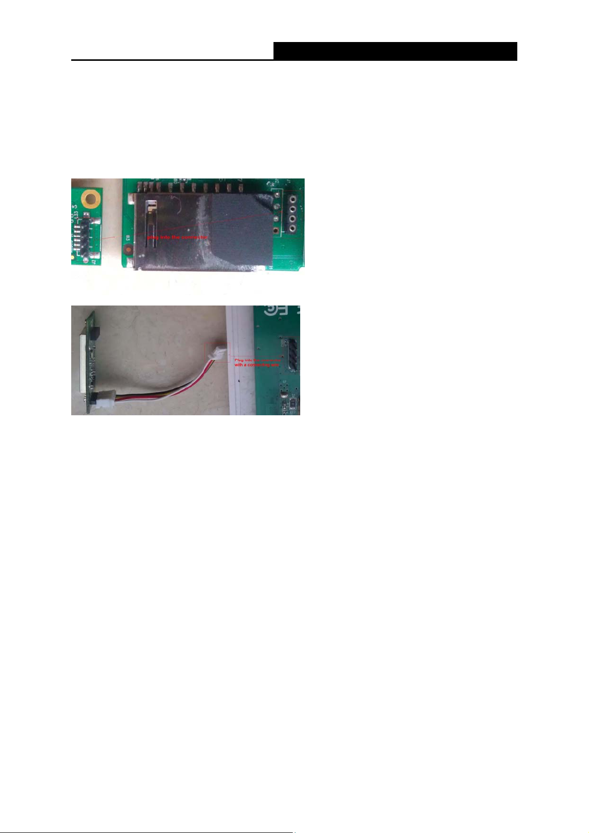
2.1 Hardware Installation
PW-MN427_56I has a 4-Pin onboard connector to transmit USB signal, and it is mainly designed
to provide stability wireless function and performance for your system.
For installation, you must be sure to connect this module to your device or system’s compatible
connector, sometimes you should use a connecting wire first. Then, the promoted Found New
Hardware Wizard will pop up if the Module is installed correctly.
2.2 Software Installation
2.2.1 Overview
The Module’s Setup Wizard will guide you through the installation of the Utility and drivers. Before
you install the software, please connect the USB Module with your computer by USB cable. After
that, you will be prompted “Found New Hardware Wizard”, click the Cancel button, and run th e
Setup Wizard program on the CD-ROM.
Note:
The Setup steps for Windows XP/ Vista/ 7 are very similar, so the following installation guide
takes Windows XP for example.
2.2.2 Installation Guide
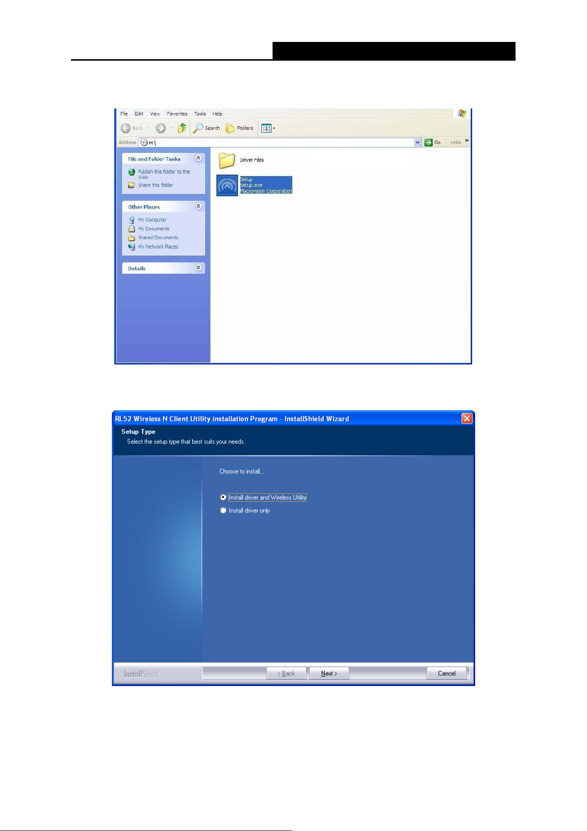
1. Insert the Resource CD into your CD-ROM drive, then go to My Computer to double-click
- 3 -
Page 8
PW-MN427_56I 150Mbps Wireless N USB Module User Guide
CD-ROM PW-MN427_56I, and you will see the screen as Figure 2-1. Double-click Setup.exe
to start the installation.
Figure 2-1 Start the Installation
2. You’ll see the screen as below. You can choose which to be installed and click Next.
Figure 2-2 Setup Type
3. In the following screen, select the configuration tool and click Next.
- 4 -
Page 9
PW-MN427_56I 150Mbps Wireless N USB Module User Guide
Figure 2-3 Setup Type
1) If you want to install the RL52 Wireless N Client Utility, please select the Wireless
Configuration Tool.
2) If you only want to use the Microsoft Zero Configuration Tool to configure the wireless
connection, please select Microsoft Zero Configuration Tool.
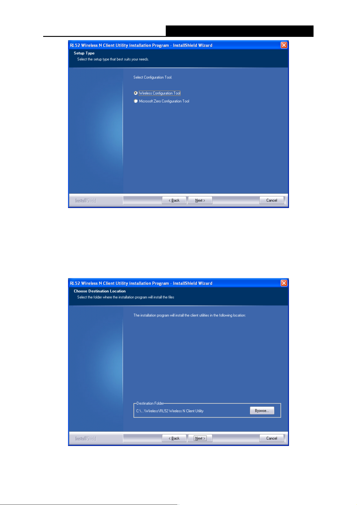
4. Choose the destination location and click Next.
Figure 2-4 Choose Destination Location
- 5 -
Page 10
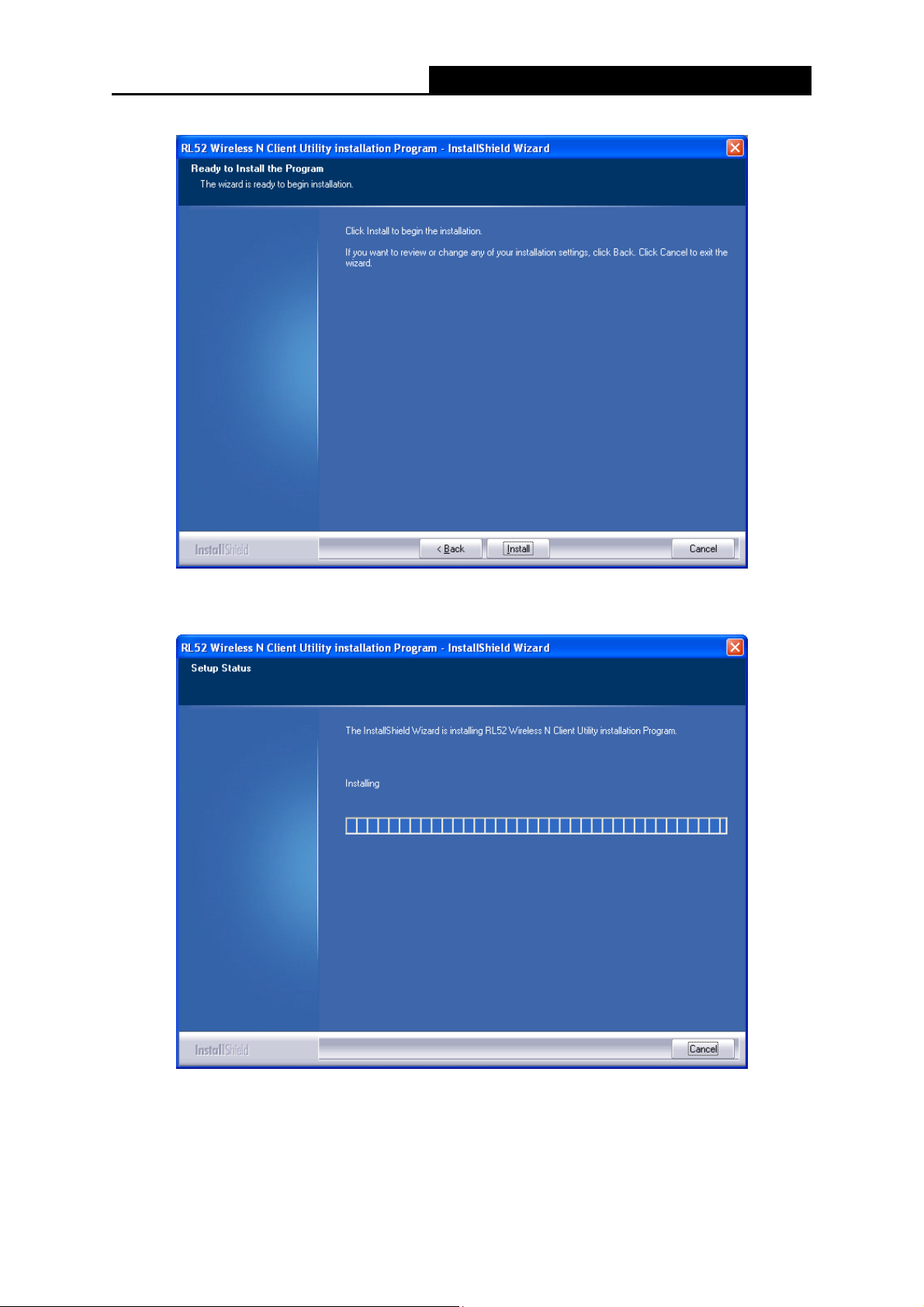
5. You will see the next screen as below. Click Install to continue.
PW-MN427_56I 150Mbps Wireless N USB Module User Guide
Figure 2-5 Ready to Install the Program
6. The following screen for installing will appear.
Figure 2-6 Setup Status
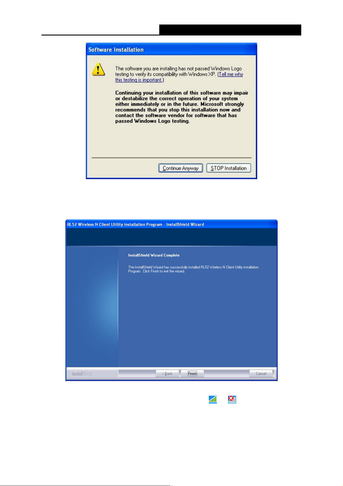
Note:
While files are copying, a warning box about Windows Logo testing (shown in Figure 2-7) may
pop up, please click Continue Anyway to continue the installation for our drivers have been
tested thoroughly and are able to work with the operating system.
- 6 -
Page 11
PW-MN427_56I 150Mbps Wireless N USB Module User Guide
Figure 2-7 Windows XP Warning Box
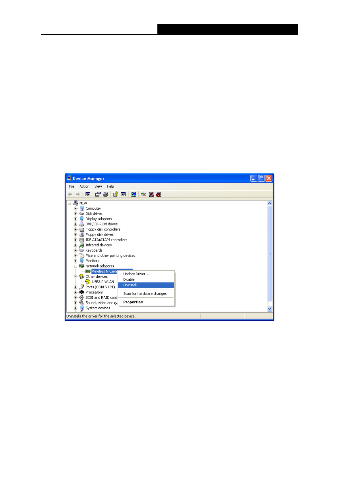
7. After the files have been successfully copied, the screen in Figure 2-8 will appear. Click the
Finish button to finish the installation and reboot the system.
Figure 2-8 InstallShield Wizard Complete
After installing the driver successfully, you should see an icon
- 7 -
or in your system tray.
Page 12
PW-MN427_56I 150Mbps Wireless N USB Module User Guide
2.3 Uninstall Software
2.3.1 Uninstall the utility software from your PC
1. On the Windows taskbar, click the Start button, point to All programsWireless, and then
click Uninstal-RL52 Wireless N Client Utility.
2. Follow the Install Shield Wizard to uninstall the utility software from your PC.
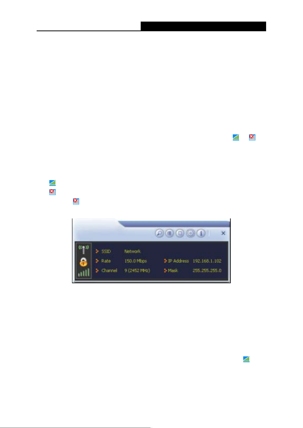
2.3.2 Uninstall the driver software from your PC
1. On the Windows taskbar, click the Start button, and then click Control Panel.
2. Click the System icon, click on the Hardware tab in the System window.
3. Click on the Device Manager button, double-click Network Modules, and then right-click
Wireless N Client Module.
Figure 2-9 Device Manager
4. Click Uninstall shown in above Figure 2-9, the system will uninstall the driver software of the
Module from your PC.
- 8 -
Page 13
PW-MN427_56I 150Mbps Wireless N USB Module User Guide
Chapter 3 Configuration
3.1 Configuration of Utility
PW-MN427_56I 150Mbps Wireless N USB Module can be configured by its utility for Windows
XP/ Vista/ 7. This section will take the configuration in Windows XP for example and guide you to
configure your 150Mbps Wireless N USB Module for wireless connectivity with trustable data
security encryption features.
The configuration steps in Windows XP/ Vista/ 7 are similar. For the configurations in Windows
Vista/ 7, please refer to the instructions in Windows XP.
, will
After the Module's driver and utility have been installed, the Module’s tray icon,
appear in your system tray. It means the utility is running on your system. If the utility does not run,
you can run the utility by clicking: Start> All programs> Wireless> RL52 Wireless N Client
Utility. If the icon still does not appear, the driver or utility may be installed incorrectly or the
Module is unplugged, please try again.
or
Icon
Icon
Right-click the
will appear as shown in the figure below.
The utility provides complete and easy manage tools to:
Display current status information
Edit and add configured profiles
Display current diagnostics information
means the connection has been established.
means there is no connection.
icon and choose Launch Config Utility, the configuration screen of the utility
Figure 3-1 Configuration Screen
Note:
If your OS is Windows XP, you can use Windows XP to configure the wireless network settings.
(To use this function, you must upgrade the OS with sp2). Just right-click the icon
bottom of the screen, and click Use Zero Configuration as Configuration utility to switch the
utility.
at the
- 9 -
Page 14
PW-MN427_56I 150Mbps Wireless N USB Module User Guide
3.1.1 Site Survey
Click the Site Survey icon on the screen of the Utility and the Site Survey screen with many
available wireless network choices will appear. The AP list will be updated every two seconds.
The AP list includes most used fields, such as SSID, network type, channel used, wireless mode,
security status and the signal percentage. The dialog box is shown in Figure 3-2.
Figure 3-2 Site Survey
(Rescan): Click the Rescan icon to refresh the list at any time.
(Add to Profile): Choose an SSID and click the Add to Profile icon to add the network to
the profile.
(Connect): Choose an SSID and click the Connect icon to connect to an available
network without adding it to the profile.
3.1.2 Profile
Click the icon on the screen of the Utility and the Profile List screen will appear as Figure 3-3.
The Profile List keeps a record of your favorite wireless settings at home, office, and other public
hot-spots. You can save multiple profiles, and activate the correct one at your preference. Figure
3-3 shows the basic profile section.
The Profile screen provides tools to:
Add a profile
Delete a profile
- 10 -
Page 15

Edit a profile
Import a profile
Export a profile
Add a WPS profile
- Click to add a new profile.
PW-MN427_56I 150Mbps Wireless N USB Module User Guide
Figure 3-3 Profile List
- Deletes an existing profile.
- Click to edit an existing profile.
- Imports an existing profile.
- Exports an existing profile.
- Add a WPS profile
Profile Name - Name of profile, preset to PROF* (* indicate 1, 2, 3...).
SSID - The access point or Ad-hoc name.
Authentication - Indicates the authentication mode used.
Encryption - Indicates the encryption type used.
3.1.2.1. Add a profile
1. Click the Add icon
on the Profile List screen (Figure 3-3), the Profile configuration screen
will appear as shown in Figure 3-4. Enter the Profile Name and choose the SSID from the
pull-down list, then click the Next icon
to continue.
- 11 -
Page 16

PW-MN427_56I 150Mbps Wireless N USB Module User Guide
Figure 3-4 Add a new profile
- Cancel button.
- Back to the previous page.
- Continue to the next page.
Profile Name - Identifies the configuration profile. This name must be unique. Profile names
are not case-sensitive.
SSID - The IEEE 802.11 wireless network name. This field has a maximum limit of 32
characters.
Network T ype: There are basically two modes of networking:
Infrastructure - All wireless clients will connect to an access point or wireless router.
Ad Hoc - Directly connecting to another computer, for peer-to-peer communication,
using wireless network Modules on each computer, such as two or more
PW-MN427_56I 150Mbps Wireless N USB Modules.
Note:
1) An Infrastructure network contains an Access Point or wireless router. All the wireless
devices or clients will connect to the wireless router or access point.
2) An Ad Hoc network contains only clients, such as laptops with wireless desktop Modules. All
the Modules must be in Ad Hoc mode to communicate.
2. In the following screen, select the corresponding Authentication mode and Encryption type
of the profile from the drop-down lists (here takes WPA2-PSK and AES for example), then
click the Next icon
to continue.
- 12 -
Page 17

PW-MN427_56I 150Mbps Wireless N USB Module User Guide
Figure 3-5 Authentication and Encryption
Authentication - You can choose the Authentication Type from the pull-down list with
seven options, Open, Shared, WPA, WPA-PSK, WPA2, WPA2-PSK, and 802.1X.
Encryption - Displays which encryption type that the Module is using. When you select
Open as Authentication, there are two options: None and WEP. If you select Shared and
802.1X as Authentication, there is only one option: WEP. When you select WPA,
WPA-PSK or WPA2-PSK as Authentication, there are two options: TKIP and AES. When
you select WPA2 as Authentication, four options are available: TKIP, AES, TKIP(MFP) and
AES(MFP).
3. In the screen that follows, enter the key of the AP in the empty field. Here takes Key
1234567890 for example. If the wireless network you are trying to connect is
security-enabled, you must enter the corresponding key to establish a successful connection.
Then click the Next icon
to continue.
Figure 3-6 Enter the Key
4. The Pre-logon Connect configuration page as shown in Figure 3-7 will then appear. Click the
Next icon
to continue.
- 13 -
Page 18

PW-MN427_56I 150Mbps Wireless N USB Module User Guide
Figure 3-7 Use Pre-logon Connection
Use Pre-logon Connection - Use ID and Password in Profile.
5. Some advanced settings can be made in Figure 3-8.
Figure 3-8 Profile
Tx Power - Manually force the AP’s transmitting power.
Use RTS Threshold - Here you can specify the RTS (Request to Send) Threshold. If you are
not sure, please leave it default here.
Use Fragment Threshold - This value is the maximum size determining whether packets will
be fragmented. Setting the Fragment Threshold too low may result in poor network
performance because of excessive packages. You are recommended to leave it default if you
are not sure about it.
6. Click the Active icon
in the screen below to connect to the chosen network. When the
screen looks like below, it shows that you have successfully added a new profile and
connected to the wireless network.
- 14 -
Page 19

PW-MN427_56I 150Mbps Wireless N USB Module User Guide
3.1.2.2. Delete a profile
Figure 3-9 Profile Added Successfully
Highlight the desired profile name on Profile List and click the Delete icon
. The profile will be
removed from the list.
Figure 3-10 Delete a Profile
3.1.2.3. Edit a profile
Highlight the desired profile name on Profile List, and click the Edit icon
, the Profile
configuration screen will appear as shown in Figure 3-11. You can make some changes of the
profile, for instance, you can change the Profile Name to name it like My Network.
- 15 -
Page 20

PW-MN427_56I 150Mbps Wireless N USB Module User Guide
3.1.2.4. Import a profile
Figure 3-11 Edit a Profile
1. From the Profile List screen (shown in Figure 3-3), click the Import icon
Profile screen will appear below.
2. Browse to the directory where the profile is located.
3. Highlight the profile name.
4. Click Open, the imported profile will then appear in the Profile List.
. Then the Import
Figure 3-12 Import a Profile
3.1.2.5. Export a profile
1. From the Profile List screen (shown in Figure 3-9), highlight the profile to be exported.
2. Click Export icon
, the Export Profile window will then appear below.
3. Browse the directory to export the profile to.
4. Click Save. The profile should then be exported to the specified location.
- 16 -
Page 21

3.1.2.6. Add a WPS profile
PW-MN427_56I 150Mbps Wireless N USB Module User Guide
Figure 3-13 Export a Profile
Click the Add WPS Profile icon
an existing network quickly in the following screen.
If the wireless card supports WPS (Wi-Fi Protected Setup) or QSS (Quick Secure Setup), you can
establish a wireless connection between wireless card and router using either Push Button
Configuration (PBC) method or PIN method. For the configuration of WPS, here takes the
Wireless Router of our company for example.
of the Utility and you can configure the WPS function to join
Figure 3-14 Profile List
Note:
To build a successful connection by WPS, you should also do the corresponding configuration of
the Access Point for WPS or QSS function meanwhile.
- 17 -
Page 22

PW-MN427_56I 150Mbps Wireless N USB Module User Guide
I. PBC Method
If your Access Point is equipped with a push-button for Wi-Fi Protected Setup, you can connect
the Module to the Access Point by Push-Button Configuration (PBC) method.
Step 1 Press the WPS button on your Access Point device.
Figure 3-15 Press the WPS Button
Step 2 Click the Add WPS Profile icon on the screen as Figure 3-14.
Step 3 Select Push-Button Configuration (PBC) on the screen below.
Step 4 Click Start PBC.
Figure 3-16 Push-Button Configuration
Figure 3-17 Start PBC
- 18 -
Page 23

PW-MN427_56I 150Mbps Wireless N USB Module User Guide
Step 5 The Module will search for the AP to establish connection automatically.
Figure 3-18
Step 6 Wait a moment until Figure 3-19 appears.
Figure 3-19
II. PIN Method
If your Access Point supports Wi-Fi Protected Setup and the PIN method, you can add the
Module to the network by the following two ways:
1) Enter the PIN into my Access Point
Step 1 Click the Add WPS Profile icon
on the screen as Figure 3-14.
Step 2 Tick PIN/numeric code and then select the desired SSID from the WPS AP List
(take Network for example) on the screen below.
- 19 -
Page 24

PW-MN427_56I 150Mbps Wireless N USB Module User Guide
Figure 3-20
Step 3 Choose the Config Mode as Enrollee and click the Next icon
below. Meanwhile, enter the PIN code of the Module (here takes 51349417 in the
screen for example) into the configuration utility of the AP. For the detailed
instructions of the AP configuration, please refer to the User Guide of the AP.
Figure 3-21 Enrollee Mode
on the screen
Step 4 Click Start PIN on the following screen.
Figure 3-22 Start PIN
Step 5 When Figure 3-19 appears, the configuration is complete.
- 20 -
Page 25

PW-MN427_56I 150Mbps Wireless N USB Module User Guide
2) Enter a PIN from my Access Point
Step 1 Click the Add WPS Profile icon
on the screen as Figure 3-14.
Step 2 Tick PIN/numeric code and then select the desired SSID from the WPS AP List
(take Network for example) on the screen below.
Figure 3-23
Step 3 Choose the Config Mode as Registrar and enter the PIN of AP (here takes
97056270 for example) into the field beside the Pin Code as Figure 3-24 shows.
For the detailed instructions of the AP configuration, please refer to the User Guide
of the AP. And then click Next icon
to continue.
Figure 3-24 Registrar Mode
Step 4 Click Start PIN on the following screen.
Figure 3-25 Start PIN
- 21 -
Page 26
PW-MN427_56I 150Mbps Wireless N USB Module User Guide
Step 5 When Figure 3-19 appears, the configuration is complete.
Note:
The default PIN code of the AP always can be found in its label or User Guide.
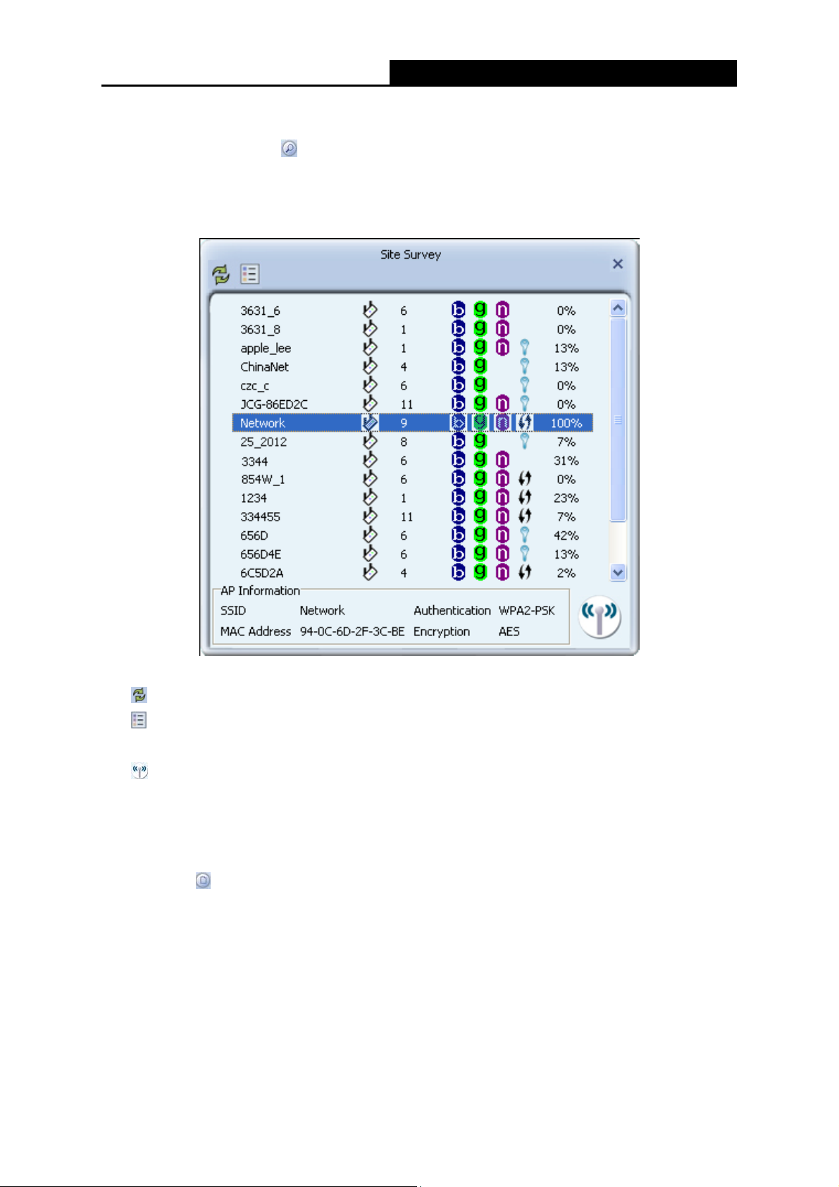
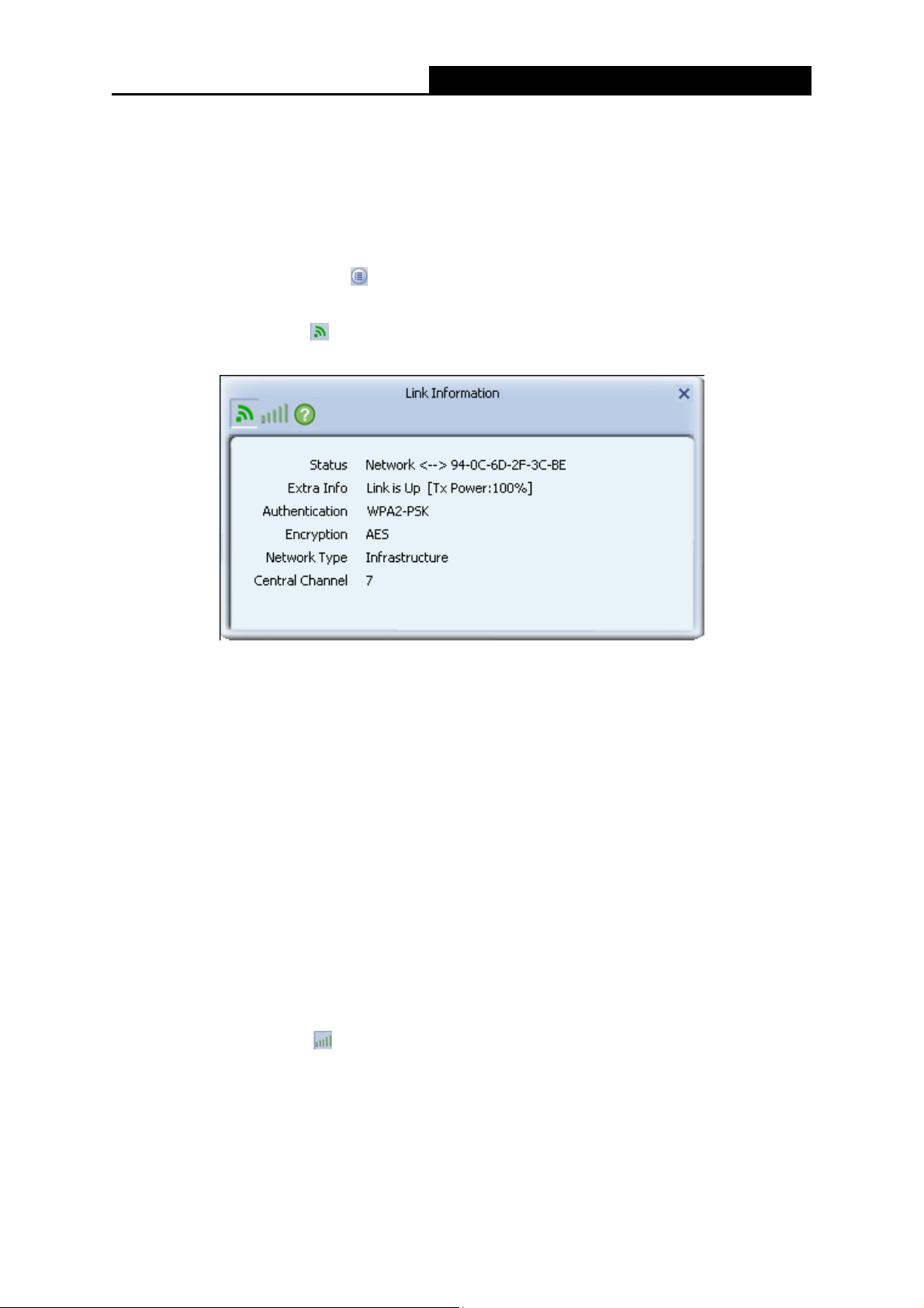
3.1.3 Link Information
Click the Link Information icon of the Utility and you will see the following screen displaying
the receiving and transmitting statistical information.
Click the Link Status icon
, you can view the current linking status of the Module as shown in
the figure below.
Figure 3-26 Link Status
The following table describes the items found on the Link Status screen.
Status - Current connection status. If no connection, it will show Disconnected. Otherwise,
the SSID and BSSID will show here.
Extra Info - Here displays the link status in use.
Authentication - Shows the authentication mode in use.
Encrtption - The encryption type in use is displayed here.
Netw ork Type - The type of network and the station currently connected are shown here.
The options include:
Infrastructure (access point)
Ad Hoc
Central Channel - The channel of the currently connected AP.
Click the Throughput icon
, you can view the Link Quality, Signal Strength and Link Speed to
see whether the Module is working well.
- 22 -
Page 27

PW-MN427_56I 150Mbps Wireless N USB Module User Guide
Figure 3-27 Throughput
Link Quality - Displays connection quality based on signal strength and TX/RX packet error
rate.
Signal Strength - This shows the strength of the signal.
Link Speed - Shows current transmit rate and receive rate.
Throughput - Displays transmit and receive throughput in unit of Mbps.
When clicking the Statistics icon
the receiving and transmitting statistical information. Click the Reset Counter icon
, you will see the following screens respectively displaying
to reset all
the counters to zero.
Figure 3-28 Transmit Statistics
Transmitted Successfully - Frames successfully sent.
Retransmitted Successfully - Successfully retransmitted frames numbers.
Fail To Receive ACK After All Retries - Frames failed to transmit after hitting retry limit.
- 23 -
Page 28

PW-MN427_56I 150Mbps Wireless N USB Module User Guide
Figure 3-29 Receive Statistics
Received Successfully - The number of frames successfully received.
Received With CRC Error - The number of frames received with a CRC error.
Dropped Due To Out-of-Resource - The number of frames dropped due to a resource
issue.
Duplicate Frames Received - The number of duplicate frames received.
3.1.4 Advanced
Click the Advanced icon of the Utility and then you can choose the wireless mode on the
following screen.
Figure 3-30 Advanced
Wireless Mode - Specifies 2.4 GHz 150 Mbps, 2.4 GHz 54 Mbps or 2.4 GHz 11 Mbps
operation in an access point network. The 150Mbps Wireless N USB Module must match the
- 24 -
Page 29

wireless mode of the access point with which it associates.
Enable TX Burst - It can translate more data when it is enabled.
Enable TCP Window Size - It can enhance the TCP throughput when it is enabled.
Fast Roaming at - Roaming will disable when Transmit Power is below some dBm if the
function is selected.
Apply - Click the Apply button to save the current setting.
PW-MN427_56I 150Mbps Wireless N USB Module User Guide
3.1.5 About
Click the About icon on the Utility screen and you will see the following screen displaying the
wireless card and driver version information.
Figure 3-31 About
Version - The version of the following items.
Utility Date - The creation date of this utility.
Driver Date - The creation date of the wireless network Module driver.
SDK Date – The creation date of the SDK.
Firmware Version -The version of the Module firmware.
EEPROM Version - The version of this EEPROM.
MAC Address - The MAC address of the wireless network Module.
Note:
For more help information, you can go to website of our company.
3.1.6 An example for application
Suppose you are using an AP, the SSID is TEST and it adopts 64-bit encryption with the key
1234567890. To establish a connection with this AP, please follow these steps below:
1. Launch RL52 Wireless N Client Utility.
2. Click the Profile icon
3. The Profile configuration screen will appear, please select SSID TEST from the drop-down
of the utility and click the Add icon on the screen that appears.
- 25 -
Page 30

list. Enter Test for the Profile Name, and select Infrastructure for the Network Type, then click
PW-MN427_56I 150Mbps Wireless N USB Module User Guide
Next icon
Encryption and click Next icon
make some advanced settings in the following screens or you are recommended to leave the
options default if you are not sure about them.
4. Highlight the profile named Test on the profile list and click Active icon
screen. The utility will establish a connection with this AP by configured profile.
to the next page. Select WPA2-PSK for the Authentication, AES for the
to continue. Enter 1234567890 for the Key. You can
on the Profile
3.2 Configure with Windows XP Wireless Zero Configuration
1. Right click the icon on the bottom of the desktop first and you will see Figure 3-32. Click
the Use Zero Configuration as Configuration Utility option to enable Wireless Zero
Configuration function.
Figure 3-32 Use Zero Configuration as Configuration utility
2. After that, double click the icon
, and the following Figure 3-33 will appear with some
available wireless network choices. You can highlight a network and then click Connect to
add to a network.
Figure 3-33 Choose a Wireless Network
Note:
If you have not installed SP2 for Windows XP, the screen above will not be available.
3. Enter the key and click Connect to continue.
- 26 -
Page 31

PW-MN427_56I 150Mbps Wireless N USB Module User Guide
Figure 3-34 Enter Network Key
4. If the connection is finished, you will see the screen as Figure 3-35 shows.
Figure 3-35 Connected
- 27 -
Page 32

PW-MN427_56I 150Mbps Wireless N USB Module User Guide
Chapter 4 AP Mode
Right click the icon to switch to AP Mode. In this mode you can use the PW-MN427_56I as a
soft AP.
Figure 4-1
Note:
At this time, if your PC has Installed other network card (wireless or wired), you will be prompted
“ICS Select WAN Module” to select one of them to be “WAN”. With this function PW-MN427_56I
can serve as wireless router based on the selected card connecting to the Internet, which will
make the APs of the LAN share the Internet.
Figure 4-2
The configuration utility screen will then appear as shown in the figure below. By clicking the
corresponding icon, you can configure the AP, make some advanced settings and view the AP’s
status. The tools section shown in the following figure respectively stands for Config AP
Advanced
right .
, Access Control List , Associate List and About from the left to the
Figure 4-3
,
- 28 -
Page 33
PW-MN427_56I 150Mbps Wireless N USB Module User Guide
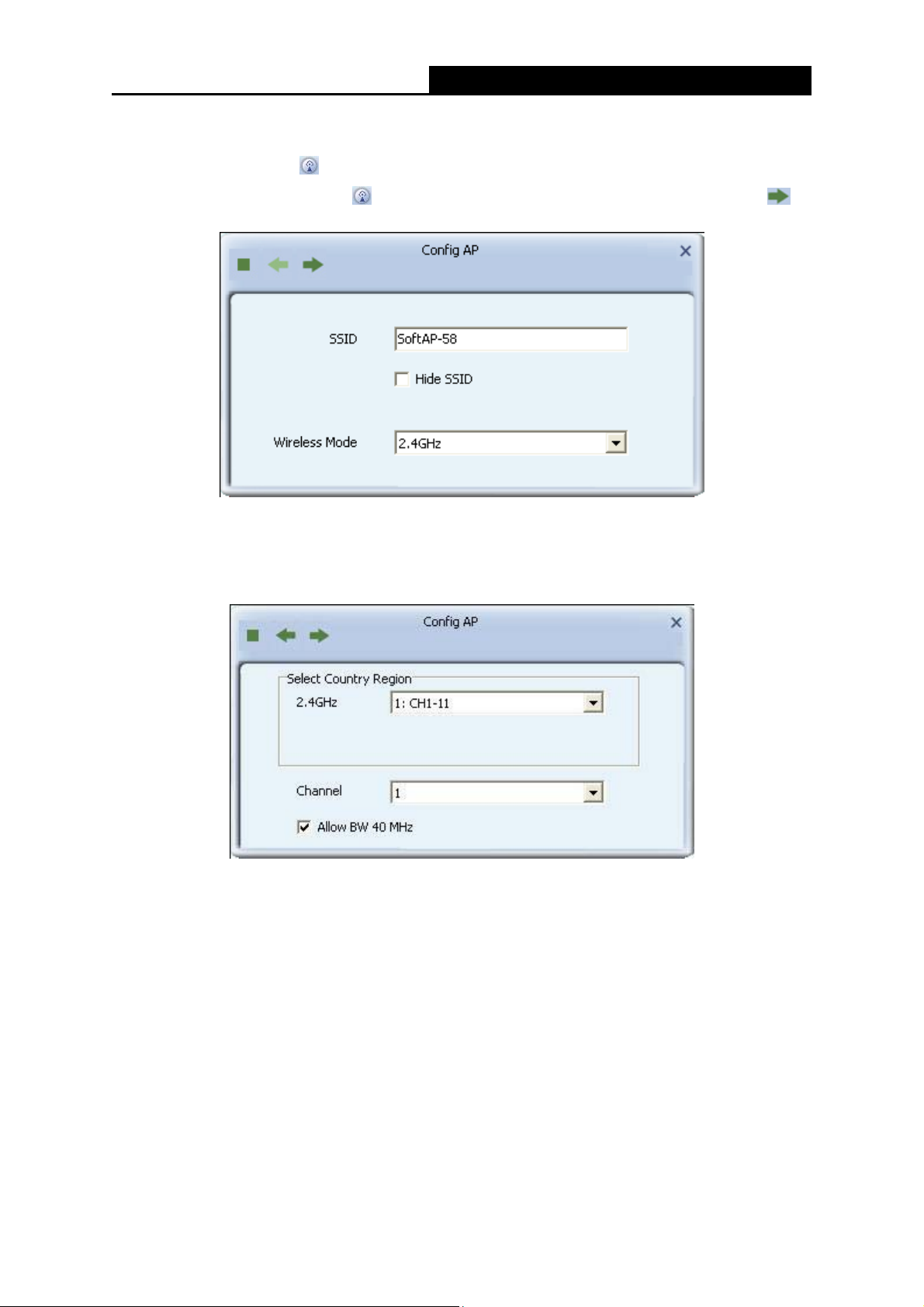
4.1 Config AP
Click the Config AP icon to load the following screen and set the AP as you need.
Step 1. Click Config AP icon
continue.
SSID - Enter the SSID of your soft AP, for example, you can name it My Network instead of
the default name SoftAP-58.
Step 2. Here you can select country region and set the AP’s channel.
, the following screen will pop up. Click Next icon to
Figure 4-4 Config AP
Figure 4-5
Channel - Select the channel from the drop-down list. This field determines which operating
frequency will be used.
Note:
There is no option about country/region for American users to choose on the software’s
interface of products.
- 29 -
Page 34

PW-MN427_56I 150Mbps Wireless N USB Module User Guide
Step 3. The AP’s authentication mode and encryption type can be set in the following figure.
Figure 4-6
Step 4. Enter the Key in the empty field to make your AP security enabled (here takes
1234567890 for example). Only by entering the corresponding key can other computers
establish a successful connection with your AP.
Figure 4-7
4.2 Advanced
Click the Advanced icon , the following screen will appear. Here you can make some
advanced settings and click Apply to make these settings take effect.
Figure 4-8
Beacon Interval(ms)- Enter a value between 20-1000 milliseconds for Beacon Interval here.
The beacons are the packets sent by the router to synchronize a wireless network. Beacon
- 30 -
Page 35

PW-MN427_56I 150Mbps Wireless N USB Module User Guide
Interval value determines the time interval of the beacons. The default value is 100.
TX Power - Manually force the AP’s transmitting power. System default is 100%.
Idle Time - Manually force the Idle Time using a selected value. The default is 300.
4.3 Access Control List
Click the Access Control List icon of the utility and the Access Control List screen will
appear as Figure 4-9. In this page, you can enable/disable the AP to connect with the specified
Mac address. Click Allow All, and enter the Mac address allowed to connect to your AP in the
empty field beside MAC Address, and then click
Highlight an existing Mac address in the list and click
Figure 4-11. When clicking
, you will clear all the Mac addresses in the Access Control List as
Figure 4-12.
to add it to the list, shown in Figure 4-10 .
to remove it from the list as shown in
Figure 4-9 Access Control Function
Access Policy - This field allows you to start the function or not. System default is disabled.
Disable - Disable the Access Policy feature.
Allow All - Allow all the MAC addresses in the Access List to access the AP.
Reject All - Disable all the MAC addresses in the Access List to access the AP.
Mac Address - Manually force the Mac address using the function.
Apply - Click to make the settings take effect.
- 31 -
Page 36

PW-MN427_56I 150Mbps Wireless N USB Module User Guide
Figure 4-10 Add an Mac Address to the List
Figure 4-11 Remove an existing Mac Address from the List
- 32 -
Page 37

PW-MN427_56I 150Mbps Wireless N USB Module User Guide
Figure 4-12 Clear All MAC Addresses
4.4 Associate List
Figure 4-13 shows the link status page. It displays detailed station information of current
connection.
Figure 4-13 Mac Table Function
MAC Address - The station’s Mac address of the current connection.
- 33 -
Page 38

AID - Raise value by current connection.
Power Saving Mode - Support Power Saving Mo de on the cur rently conne cted station.
Status - The link status of the current connection.
PW-MN427_56I 150Mbps Wireless N USB Module User Guide
4.5 About
The About page displays the wireless card and driver version information as shown in Figure
4-14.
Figure 4-14 About Page
- 34 -
Page 39

PW-MN427_56I 150Mbps Wireless N USB Module User Guide
Chapter 5 Example for Application
5.1 Configuration of PSP XLink Online game
Please ensure the software and hardware environments are well established before configuring.
For hardware, at least a PC, a PW-MN427_56I 150Mbps Wireless N USB Module and a PSP
device are needed. For software, the PW-MN427_56I Module driver should be properly installed.
Please operate as follows:
Step 1. Connect the website of X-LINK http://www.teamxlink.co.uk/ to register, and download
the latest software of X-LINK Kai.
Step 2. Install the X-LINK Kai software, click Start > All programs > XLink Kai > Configure Kai,
then set as Figure 5-1.
Figure 5-1
Step 3. After completing the settings, please click Start > All programs > XLink Kai > Start Kai
to connect to XLink Kai.
Step 4. Open the wireless mode of the PSP device, and then start an internet game.
- 35 -
Page 40

Step 5. Right-click “My Computer” and select Management. In the prompt page, click Device
Manager, then right-click “Wireless N Client Module “and select Properties. Then set
the value of “PSP Xlink Mode” as Enable following the red marked instruction in the
figure.
PW-MN427_56I 150Mbps Wireless N USB Module User Guide
Figure 5-2
Step 6. Click Start > Control Panel > Network.
Figure 5-3
Step 7. Right-click Wireless Network Connection icon , and select Properties. In the
following prompt page, highlight Internet Protocol (TCP/IP) and click Properties.
- 36 -
Page 41

PW-MN427_56I 150Mbps Wireless N USB Module User Guide
Figure 5-4
Step 8. In the prompt page shown below, select Use the Following IP Address, and set the IP
and Subnet mask. After completing setting, click OK.
Figure 5-5
Note:
Please set the IP address in different network segment with the other network card to avoid
conflict.
Step 9. Launch RL52 Wireless N Client Utility, then highlight the Network Name (SSID)
beginning with “PSP” in the “Network” page, and click Connect.
Step 10. Check whether your PSP device is detected in the Diagnostics mode of Kai as Figure
5-6 shown: Click the icon
first and then click the folder .
- 37 -
Page 42

PW-MN427_56I 150Mbps Wireless N USB Module User Guide
Figure 5-6
Step 11. Click the icon on the right top corner to enter the Arena Mode, highlight the arena of
your wanted game, and then join or start a new game.
Figure 5-7
- 38 -
Page 43

PW-MN427_56I 150Mbps Wireless N USB Module User Guide
Appendix A: Glossary
802.11b - The 802.11b standard specifies a wireless networking at 11 Mbps using
direct-sequence spread-spectrum (DSSS) technology and operating in the unlicensed radio
spectrum at 2.4GHz, and WEP encryption for security. 802.11b networks are also referred to as
Wi-Fi networks.
802.11g - Specification for wireless networking at 54 Mbps using direct-sequence
spread-spectrum (DSSS) technology, using OFDM modulation and operating in the unlicensed
radio spectrum at 2.4GHz, and backward compatibility with IEEE 802.11b devices, and WEP
encryption for security.
802.11n - 802.11n builds upon previous 802.11 standards by adding MIMO (multiple-input
multiple-output). MIMO uses multiple transmitter and HreceiverH antennas to allow for increased
data throughput via spatial multiplexing and increased range by exploiting the spatial diversity,
perhaps through coding schemes like Alamouti coding. The Enhanced Wireless Consortium
[3]
U
(EWC)
technology specification for interoperability of next-generation wireless local area networking
(WLAN) products.
UH
H
was formed to help accelerate the IEEE 802.11n development process and promote a
Ad-hoc Network - An ad-hoc network is a group of computers, each with a 150Mbps Wireless N
USB Module, connected as an independent 802.11 wireless LAN. Ad-hoc wireless computers
operate on a peer-to-peer basis, communicating directly with each other without the use of an
access point. Ad-hoc mode is also referred to as an Independent Basic Service Set (IBSS) or as
peer-to-peer mode, and is useful at a departmental scale or SOHO operation.
DSSS (Direct-Sequence Spread Spectrum) - DSSS generates a redundant bit pattern for all data
transmitted. This bit pattern is called a chip (or chipping code). Even if one or more bits in the chip
are damaged during transmission, statistical techniques embedded in the receiver can recover
the original data without the need for retransmission. To an unintended receiver, DSSS appears
as low power wideband noise and is rejected (ignored) by most narrowband receivers. However,
to an intended receiver (i.e. another wireless LAN endpoint), the DSSS signal is recognized as the
only valid signal, and interference is inherently rejected (ignored).
FHSS (Frequency Hopping Spread Spectrum) - FHSS continuously changes (hops) the carrier
frequency of a conventional carrier several times per second according to a pseudo-random set of
channels. Because a fixed frequency is not used, and only the transmitter and receiver know the
hop patterns, interception of FHSS is extremely difficult.
Infrastructure Network - An infrastructure network is a group of computers or other devices,
each with a 150Mbps Wireless N USB Module, connected as an 802.11 wireless LAN. In
infrastructure mode, the wireless devices communicate with each other and to a wired network by
first going through an access point. An infrastructure wireless network connected to a wired
network is referred to as a Basic Service Set (BSS). A set of two or more BSS in a single network
is referred to as an Extended Service Set (ESS). Infrastructure mode is useful at a corporation
scale, or when it is necessary to connect the wired and wireless networks.
- 39 -
Page 44

PW-MN427_56I 150Mbps Wireless N USB Module User Guide
Spread Spectrum - Spread Spectrum technology is a wideband radio frequency technique
developed by the military for use in reliable, secure, mission-critical communications systems. It is
designed to trade off bandwidth efficiency for reliability, integrity, and security. In other words,
more bandwidth is consumed than in the case of narrowband transmission, but the trade off
produces a signal that is, in effect, louder and thus easier to detect, provided that the receiver
knows the parameters of the spread-spectrum signal being broadcast. If a receiver is not tuned to
the right frequency, a spread-spectrum signal looks like background noise. There are two main
alternatives, Direct Sequence Spread Spectrum (DSSS) and Frequency Hopping Spread
Spectrum (FHSS).
SSID - A Service Set Identification is a thirty-two character (maximum) alphanumeric key
identifying a wireless local area network. For the wireless devices in a network to communicate
with each other, all devices must be configured with the same SSID. This is typically the
configuration parameter for a wireless PC card. It corresponds to the ESSID in the wireless
Access Point and to the wireless network name.
WEP (Wired Equivalent Privacy) - A data privacy mechanism based on a 64-bit or 128-bit shared
key algorithm, as described in the IEEE 802.11 standard.
Wi-Fi - A trade name for the 802.11b wireless networking standard, given by the Wireless
Ethernet Compatibility Alliance (WECA, see http://www.wi-fi.net), an industry standards group
promoting interoperability among 802.11b devices.
WLAN (Wireless Local Area Network) - A group of computers and associated devices
communicate with each other wirelessly, which network serving users are limited in a local area.
WPA (Wi-Fi Protected Access) - A wireless security protocol use TKIP (Temporal Key Integrity
Protocol) encryption, which can be used in conjunction with a RADIUS server.
- 40 -
Page 45

PW-MN427_56I 150Mbps Wireless N USB Module User Guide
Appendix B: Specifications
General
Interface USB 2.0 Interface
Standards IEEE 802.11n, IEEE 802.11g, IEEE 802.11b
Operating System Windows XP/ Vista/ 7
Safety & Emission FCC, CE
2.412 ~ 2.472 GHz (For CE Area)
Frequency
2.412 ~ 2.462 GHz (For FCC Area)
130M: -68dBm
Sensitivity
Spread Spectrum Direct Sequence Spread Spectrum (DSSS)
Wireless
Radio Data Rate Up to 150Mbps
Modulation
Media Access Protocol CSMA/CA with ACK
Data Security WPA, 64/128 bits WEP, TKIP/AES, IEEE802.1X authentication
Physical Environmental
Working Temperature 0℃~40℃ (32℉~104 )℉
Storage Temperature -40℃~70℃ (-40℉~158 )℉
Humidity 10%~90% RH, Non-condensing
54M: -68dBm
11M: -85dBm
11n OFDM,
11g OFDM , 11b CCK/DSSS
* Only 2.412GHz~2.462GHz is allowed to be used in USA, which means only channel 1~11 is
available for American users to choose.
- 41 -
 Loading...