

Page 1

PW-3G401M
3G Wireless N Nano Router
Rev: 1.0.0
1910020515
Page 2

FCC STATEMENT
This equipment has been tested and found to comply with the limits for a Class B digital device,
pursuant to part 15 of the FCC Rules. These limits are designed to provide reasonable protection
against harmful interference in a residential installation. This equipment generates, uses and can
radiate radio frequency energy and, if not installed and used in accordance with the instructions,
may cause harmful interference to radio communications. However, there is no guarantee that
interference will not occur in a particular installation. If this equipment does cause harmful
interference to radio or television reception, which can be determined by turning the equipment off
and on, the user is encouraged to try to correct the interference by one or more of the following
measures:
• Reorient or relocate the receiving antenna.
• Increase the separation between the equipment and receiver.
• Connect the equipment into an outlet on a circuit different from that to which the
receiver is connected.
• Consult the dealer or an experienced radio/ TV technician for help.
This device complies with part 15 of the FCC Rules. Operation is subject to the following two
conditions:
1) This device may not cause harmful interference.
2) This device must accept any interference received, including interference that may cause
undesired operation.
Any changes or modifications not expressly approved by the party responsible for compliance
could void the user’s authority to operate the equipment.
Note: The manufacturer is not responsible for any radio or tv interference caused by
unauthorized modifications to this equipment. Such modifications could void the user’s authority
to operate the equipment.
FCC RF Radiation Exposure Statement
This equipment complies with FCC RF radiation exposure limits set forth for an uncontrolled
environment. This device and its antenna must not be co-located or operating in conjunction
with any other antenna or transmitter.
“To comply with FCC RF exposure compliance requirements, this grant is applicable to only
Mobile Configurations. The antennas used for this transmitter must be installed to provide a
separation distance of at least 20 cm from all persons and must not be co-located or operating
in conjunction with any other antenna or transmitter.”
I
Page 3

CE Mark Warning
This is a class B product. In a domestic environment, this product may cause radio interference,
in which case the user may be required to take adequate measures.
National restrictions
This device is intended for home and office use in all EU countries (and other countries following
the EU directive 1999/5/EC) without any limitation except for the countries mentioned below:
Country Restriction Reason/remark
Bulgaria None
Outdoor use limited to 10
France
Italy None
Luxembourg None
Norway Implemented
Russian Federation None Only for indoor applications
mW e.i.r.p. within the band
2454-2483.5 MHz
General authorization required for outdoor use and
public service
Military Radiolocation use. Refarming of the 2.4 GHz
band has been ongoing in recent years to allow current
relaxed regulation. Full implementation planned 2012
If used outside of own premises, general authorization is
required
General authorization required for network and service
supply(not for spectrum)
This subsection does not apply for the geographical area
within a radius of 20 km from the centre of Ny-Ålesund
Note: Please don’t use the product outdoors in France.
II
Page 4

CONTENTS
Package Contents .......................................................................................................................... 1
Chapter 1. Introduction................................................................................................................. 2
1.1 Overview of the Router................................................................................................. 2
1.2 Conventions ................................................................................................................. 2
1.3 Main Features .............................................................................................................. 3
1.4 Panel Layout ................................................................................................................ 4
Chapter 2. Connecting the Router............................................................................................... 5
2.1 System Requirements .................................................................................................. 5
2.2 Installation Environment Requirements ........................................................................ 5
2.3 Connecting the Router ................................................................................................. 5
Chapter 3. Quick Installation Guide............................................................................................. 9
3.1 3G/4G Router Mode..................................................................................................... 9
3.1.1 PC configuration ............................................................................................... 9
3.1.2 Connect to Network .......................................................................................... 9
3.1.3 Router Configuration......................................................................................... 9
3.2 Wireless Router Mode ................................................................................................ 14
3.2.1 PC configuration ............................................................................................. 14
3.2.2 Connect to Network ........................................................................................ 14
3.2.3 Router Configuration....................................................................................... 15
3.3 Standard AP Mode ..................................................................................................... 20
3.3.1 PC configuration ............................................................................................. 20
3.3.2 Connect to Network ........................................................................................ 21
3.3.3 Router Configuration....................................................................................... 21
Chapter 4. Router Configuration – 3G Router Mode ................................................................. 29
4.1 Login .......................................................................................................................... 29
4.2 Status ......................................................................................................................... 29
4.3 Quick Setup................................................................................................................ 30
4.4 Operation Mode.......................................................................................................... 31
4.5 WPS ........................................................................................................................... 31
4.6 Network ...................................................................................................................... 36
4.6.1 Internet Access ............................................................................................... 36
4.6.2 3G/4G ............................................................................................................. 37
4.6.3 WAN ............................................................................................................... 41
4.6.4 MAC Clone ..................................................................................................... 51
I
Page 5

4.6.5 LAN................................................................................................................. 51
4.7 Wireless ..................................................................................................................... 52
4.7.1 Wireless Settings............................................................................................ 52
4.7.2 Wireless Security............................................................................................ 55
4.7.3 Wireless MAC Filtering ................................................................................... 58
4.7.4 Wireless Advanced ......................................................................................... 60
4.7.5 Wireless Statistics........................................................................................... 61
4.8 DHCP ......................................................................................................................... 62
4.8.1 DHCP Settings ............................................................................................... 62
4.8.2 DHCP Clients List ........................................................................................... 64
4.8.3 Address Reservation ...................................................................................... 64
4.9 Forwarding ................................................................................................................. 65
4.9.1 Virtual Servers ................................................................................................ 66
4.9.2 Port Triggering ................................................................................................ 67
4.9.3 DMZ................................................................................................................ 69
4.9.4 UPnP .............................................................................................................. 70
4.10 Security ...................................................................................................................... 71
4.10.1 Basic Security................................................................................................. 71
4.10.2 Advanced Security.......................................................................................... 72
4.10.3 Local Management ......................................................................................... 74
4.10.4 Remote Management ..................................................................................... 75
4.11 Parental Control ......................................................................................................... 76
4.12 Access Control ........................................................................................................... 78
4.12.1 Rule ................................................................................................................ 78
4.12.2 Host ................................................................................................................ 84
4.12.3 Target.............................................................................................................. 86
4.12.4 Schedule......................................................................................................... 88
4.13 Advanced Routing ...................................................................................................... 90
4.13.1 Static Routing List ........................................................................................... 90
4.13.2 System Routing Table..................................................................................... 91
4.14 Bandwidth Control ...................................................................................................... 92
4.14.1 Control Settings .............................................................................................. 92
4.14.2 Rules List........................................................................................................ 92
4.15 IP & MAC Binding....................................................................................................... 93
4.15.1 Binding Settings.............................................................................................. 94
4.15.2 ARP List.......................................................................................................... 95
4.16 Dynamic DNS............................................................................................................. 96
II
Page 6

4.16.1 Comexe.cn DDNS .......................................................................................... 96
4.16.2 Dyndns.org DDNS .......................................................................................... 97
4.16.3 No-ip.com DDNS ............................................................................................ 98
4.17 System Tools .............................................................................................................. 99
4.17.1 Time Settings................................................................................................ 100
4.17.2 Diagnostic..................................................................................................... 101
4.17.3 Firmware Upgrade........................................................................................ 103
4.17.4 Factory Defaults ........................................................................................... 104
4.17.5 Backup & Restore......................................................................................... 104
4.17.6 Reboot.......................................................................................................... 105
4.17.7 Password...................................................................................................... 106
4.17.8 System Log................................................................................................... 106
4.17.9 Statistics ....................................................................................................... 107
Chapter 5. Router Configuration – Wireless Router Mode ..................................................... 109
5.1 Login ........................................................................................................................ 109
5.2 Status ....................................................................................................................... 109
5.3 Quick Setup...............................................................................................................110
5.4 Operation Mode......................................................................................................... 111
5.5 WPS ..........................................................................................................................111
5.6 Network .....................................................................................................................116
5.6.1 WAN ..............................................................................................................116
5.6.2 MAC Clone ................................................................................................... 126
5.6.3 LAN............................................................................................................... 126
5.7 Wireless ................................................................................................................... 127
5.7.1 Wireless Settings.......................................................................................... 127
5.7.2 Wireless Security.......................................................................................... 130
5.7.3 Wireless MAC Filtering ................................................................................. 133
5.7.4 Wireless Advanced ....................................................................................... 135
5.7.5 Wireless Statistics......................................................................................... 136
5.8 DHCP ....................................................................................................................... 137
5.8.1 DHCP Settings ............................................................................................. 137
5.8.2 DHCP Clients List ......................................................................................... 139
5.8.3 Address Reservation .................................................................................... 139
5.9 Forwarding ............................................................................................................... 140
5.9.1 Virtual Servers .............................................................................................. 141
5.9.2 Port Triggering .............................................................................................. 142
5.9.3 DMZ.............................................................................................................. 144
III
Page 7

5.9.4 UPnP ............................................................................................................ 145
5.10 Security .................................................................................................................... 146
5.10.1 Basic Security............................................................................................... 146
5.10.2 Advanced Security........................................................................................ 148
5.10.3 Local Management ....................................................................................... 149
5.10.4 Remote Management ................................................................................... 150
5.11 Parental Control ....................................................................................................... 151
5.12 Access Control ......................................................................................................... 154
5.12.1 Rule .............................................................................................................. 154
5.12.2 Host .............................................................................................................. 160
5.12.3 Target............................................................................................................ 162
5.12.4 Schedule....................................................................................................... 164
5.13 Advanced Routing .................................................................................................... 166
5.13.1 Static Routing List ......................................................................................... 166
5.13.2 System Routing Table................................................................................... 167
5.14 Bandwidth Control .................................................................................................... 168
5.14.1 Control Settings ............................................................................................ 168
5.14.2 Rules List...................................................................................................... 168
5.15 IP & MAC Binding..................................................................................................... 169
5.15.1 Binding Settings............................................................................................ 170
5.15.2 ARP List........................................................................................................ 171
5.16 Dynamic DNS........................................................................................................... 172
5.16.1 Comexe.cn DDNS ........................................................................................ 172
5.16.2 Dyndns.org DDNS ........................................................................................ 173
5.16.3 No-ip.com DDNS .......................................................................................... 174
5.17 System Tools ............................................................................................................ 175
5.17.1 Time Settings................................................................................................ 176
5.17.2 Diagnostic..................................................................................................... 177
5.17.3 Firmware Upgrade........................................................................................ 179
5.17.4 Factory Defaults ........................................................................................... 180
5.17.5 Backup & Restore......................................................................................... 180
5.17.6 Reboot.......................................................................................................... 181
5.17.7 Password...................................................................................................... 182
5.17.8 System Log................................................................................................... 182
5.17.9 Statistics ....................................................................................................... 183
Chapter 6. Router Configuration— Standard AP Mode ......................................................... 185
6.1 Login ........................................................................................................................ 185
IV
Page 8

6.2 Status ....................................................................................................................... 185
6.3 Quick Setup.............................................................................................................. 187
6.4 Operation Mode........................................................................................................ 187
6.5 WPS ......................................................................................................................... 188
6.6 Network .................................................................................................................... 192
6.7 Wireless ................................................................................................................... 193
6.7.1 Wireless Settings.......................................................................................... 194
6.7.2 Wireless Security.......................................................................................... 201
6.7.3 Wireless MAC Filtering ................................................................................. 208
6.7.4 Wireless Advanced ........................................................................................211
6.7.5 Wireless Statistics......................................................................................... 212
6.8 DHCP ....................................................................................................................... 213
6.8.1 DHCP Settings ............................................................................................. 213
6.8.2 DHCP Clients List ......................................................................................... 214
6.8.3 Address Reservation .................................................................................... 215
6.9 System Tools............................................................................................................ 216
6.9.1 Time Settings................................................................................................ 217
6.9.2 Diagnostic..................................................................................................... 218
6.9.3 Firmware Upgrade ........................................................................................ 220
6.9.4 Factory Defaults ........................................................................................... 221
6.9.5 Backup & Restore......................................................................................... 221
6.9.6 Reboot .......................................................................................................... 222
6.9.7 Password...................................................................................................... 223
6.9.8 System Log................................................................................................... 223
6.9.9 Statistics ....................................................................................................... 224
Appendix A: FAQ........................................................................................................................ 226
Appendix B: Configuring the PCs............................................................................................. 231
Appendix C: Specifications....................................................................................................... 235
Appendix D: Glossary................................................................................................................ 236
Appendix E: Compatible 3G/4G USB Modem .......................................................................... 238
V
Page 9

PW-3G401M 3G Wireless N Nano Router
Package Contents
The following items should be found in your package:
¾ PW-3G401M 3G Wireless N Nano Router
¾ Power Adapter for PW-3G401M 3G Wireless N Nano Router
¾ USB Cable
¾ Ethernet cable
¾ Quick Installation Guide
¾ Resource CD for PW-3G401M 3G Wireless N Nano Router, including:
• This Guide
• Other Helpful Information
Note:
)
Make sure that the package contains the above items. If any of the listed items is damaged or
missing, please contact your distributor.
-1-
Page 10

PW-3G401M 3G Wireless N Nano Router
Chapter 1. Introduction
1.1 Overview of the Router
PW-3G401M gives you the freedom to quickly set up a stable and high speed wireless network,
up to 150Mbps, on-the-go and share a 3G/4G connection. By connecting a UMTS/HSPA/EVDO
USB Card to the Router, a Wi-Fi hotspot is instantly established allowing users to share a
Internet connection anywhere 3G/4G coverage is available. So whether you’re on the train,
camping, or at a construction site, you’ll have a reliable wireless connection to accommodate
your networking needs.
Flexible Network Connection
PW-3G401M 3G Wireless N Nano Router provides 3G Router, Wireless Router and Standard
AP modes for network connection, providing the best flexibility. The Router supports 3G/4G and
WAN (PPPoE, Dynamic IP, Static IP, PPTP, L2TP Cable) broadband connections for Internet
access. You can visit the Internet no matter at home or outside on business.
PW-3G401M 3G Wireless N Nano Router is compatible with iPad, iTouch, Android Phone,
Kindle and majority portable WiFi devices. With a standard USB 2.0 port for 3G/4G Modem, the
Router is compatible with UMTS/HSPA/EVDO USB 3G/4G modems.
PW-3G401M 3G Wireless N Nano Router provides up to 150Mbps, faster than that of traditional
11g products, surpasses 11g performance enabling the use of high bandwidth-consuming
applications such as HD Videos. It provides 150Mbps wireless connectivity for the network
share on the go.
With a Mini USB port, the Router can be powered by laptop or Power Adapter with Low Power
consumption.
Excellent Compatibility
Incredibly High Speed
Low Power Consumption
1.2 Conventions
The Router or PW-3G401M mentioned in this guide stands for PW-3G401M 3G Wireless N
Nano Router without any explanation.
-2-
Page 11

PW-3G401M 3G Wireless N Nano Router
1.3 Main Features
¾ Travel size design, small enough to take on the road
¾ One 10/100M Auto-Negotiation RJ45 Ethernet port, one USB 2.0 Port, one mini USB port
¾ Compatible with IEEE 802.11n/g/b, IEEE802.3/3u
¾ Compatible with UMTS/HSPA/EVDO USB 3G/4G Modem
¾ Compatible with iPad, iTouch, Android Phone, Kindle and majority portable WiFi devices
¾ Wireless Lite N speed up to 150Mbps
¾ Supports WPS one button security setup
¾ Provides WEP, WPA/WPA2, WPA-PSK/WPA2-PSK authentication, TKIP/AES encryption
security
¾ Powered by laptop or Power Adapter with Low Power Consumption
¾ Supports 3G/4G Router Mode, WISP Client Router Mode, and AP Mode
¾ Supports 3G/4G/PPPoE/Dynamic IP/Static IP/PPTP/L2TP Cable Internet access
¾ Supports VPN Pass-through, Virtual Server and DMZ Host
¾ Supports UPnP, Dynamic DNS, Static Routing
¾ Provides Automatic-connection and Scheduled Connection on certain time to the Internet
¾ Built-in NAT and DHCP server supporting automatic and dynamic IP address IP address
distribution
¾ Connects Internet on demand and disconnects from the Internet when idle for PPPoE
¾ Provides 64/128/152-bit WEP encryption security and wireless LAN ACL (Access Control
List)
¾ Supports Flow Statistics
¾ Supports firmware upgrade and Web management
-3-
Page 12
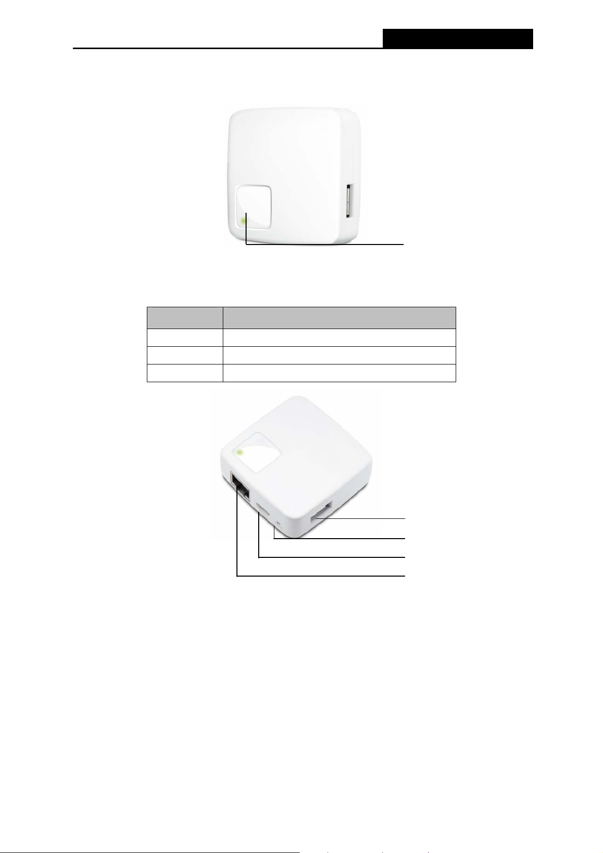
1.4 Panel Layout .4 Panel Layout
PW-3G401M 3G Wireless N Nano Router
Figure 1-1 Front Panel sketch
To check the different status of the LED:
Status Indication
On The Router is working properly.
Flashing The Router is transferring data.
Off The Router is not working properly.
LED
3G USB Modem Port
Reset Button
Mini USB Port
LAN/WAN Port
Figure 1-2 Rear Panel sketch
¾ 3G USB Modem Port: This port is used to plug a 3G modem/card.
¾ Reset Button: Use a pin to press the button for several minutes when the LED flashes, you
can reset the Router to its factory defaults.
¾ Mini USB Port: This port is used to connect the provided power adapter.
¾ LAN/WAN Port: This RJ45 Ethernet port can be LAN or WAN port depending on the
working mode.
-4-
Page 13

PW-3G401M 3G Wireless N Nano Router
Chapter 2. Connecting the Router
2.1 System Requirements
¾ 3G/4G Mobile Broadband Internet Access Service (With a UMTS/HSPA/EVDO USB
dongle)
¾ PCs with a working Ethernet Adapter and an Ethernet cable with RJ45 connectors
¾ TCP/IP protocol on each PC
¾ Web browser, such as Microsoft Internet Explorer 5.0 , Netscape Navigator 6.0 or above
2.2 Installation Environment Requirements
¾ Place the Router in a well ventilated place far from any heater or heating vent
¾ Avoid direct irradiation of any strong light (such as sunlight)
¾ Keep at least 2 inches (5 cm) of clear space around the Router
¾ Operating Temperature: 0 ~40 (32 ~104 )℃℃℉ ℉
¾ Operating Humidity: 10%~90%RH, Non-condensing
2.3 Connecting the Router
There are totally six operation modes supported by this Router: 3G Router, Wireless Router,
Standard AP (including Access Point, Repeater, Bridge with AP, and Client). Please connect
your devices according to the mode you are going to apply.
Note: Before hardware connection, please write down the SSID and Password on the label of
your PW-3G401M for later use.
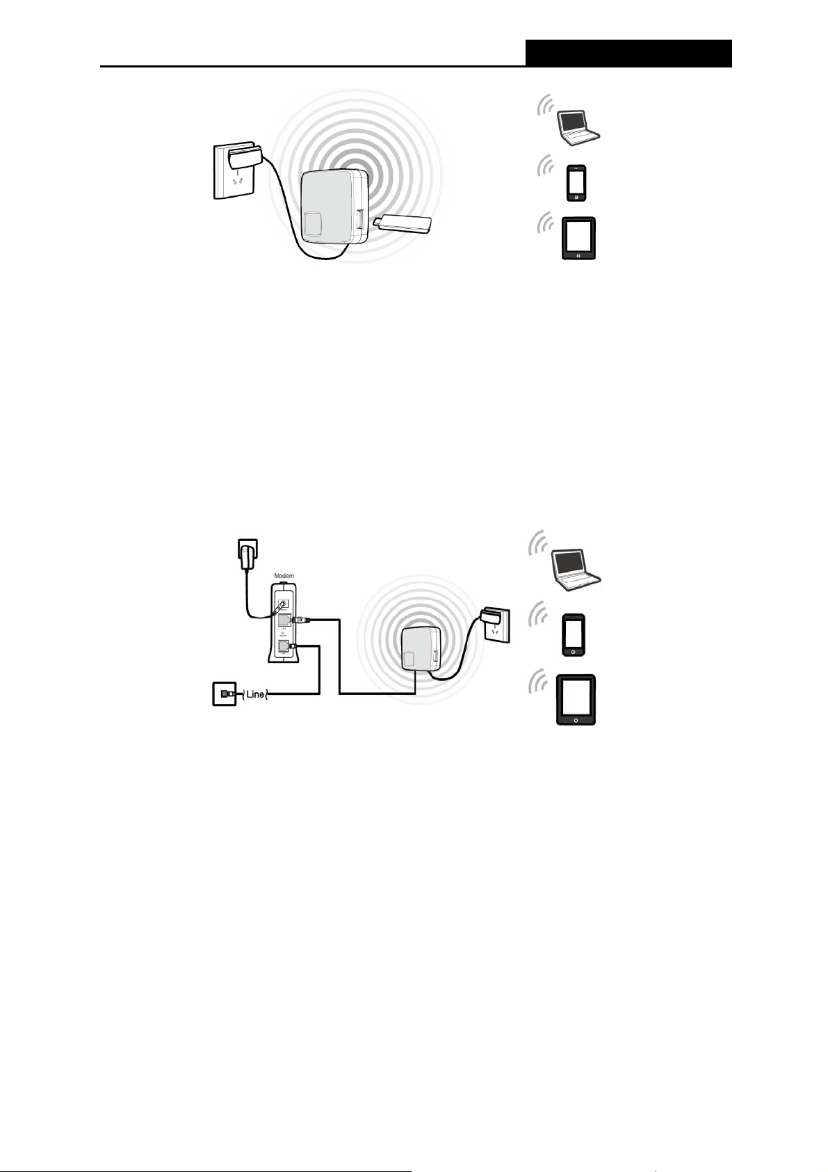
¾ 3G Router Mode
By default, PW-3G401M is used as 3G Router. Plug your 3G modem into the USB port, configure
the necessary parameters on the web-based management page of the Router, and then you can
enjoy the Internet. In this mode, the LAN/WAN port is used as LAN port for wired connection with
your computer. Other devices can share the Internet wirelessly.
-5-
Page 14
PW-3G401M 3G Wireless N Nano Router
1. Connect one end of the provided USB cable to mini USB port of the Router and the other
end to the power adapter, and then plug the power adapter to a standard electrical wall
socket.
2. Connect the 3G/4G modem/card to the 3G/4G USB port of the Router.
3. Connect the notebook/PC to the Router via an ethernet cable or wirelessly.
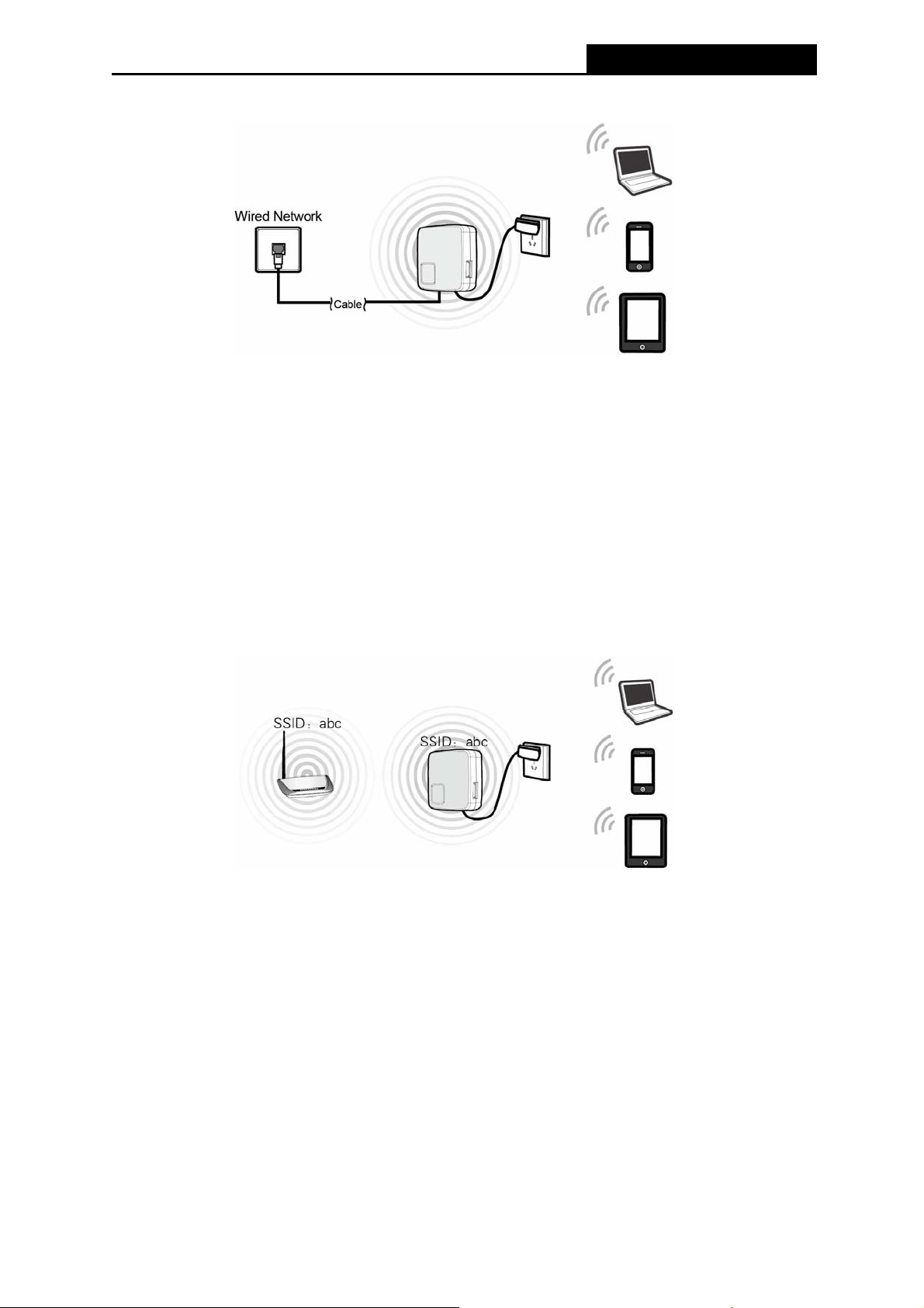
¾ Wireless Router Mode
In this mode, TD-W8951ND enables multiple users to share Internet via DSL/Cable modem. Here,
the LAN/WAN port is used as WAN port to connect the Router with the DSL/Cable modem.
1. Connect one end of the provided USB cable to mini USB port of the Router and the other
end to the power adapter, and then plug the power adapter to a standard electrical wall
socket.
2. Connect the LAN/WAN port of the Router with the LAN port of the DSL modem via an
Ethernet cable.
3. Connect the notebook/PC to the Router wirelessly.
¾ Standard AP Mode
Under Standard AP Mode, there are four specific wireless mode: Access Point, Repeater, Bridge
with AP, and Client.
z Access Point
Access point is used to convert wired network to wireless one. In this mode, the LAN/WAN port
works as LAN port to connect with the wired network via Ethernet cable. Users then can
-6-
Page 15
PW-3G401M 3G Wireless N Nano Router
connect to the network wirelessly by means of PW-3G401M.
1. Connect one end of the provided USB cable to mini USB port of the Router and the other
end to the power adapter, and then plug the power adapter to a standard electrical wall
socket.
2. Connect the LAN/WAN port of the Router to the wired network port via an Ethernet cable.
3. Connect the notebook/PC to the Router wirelessly.
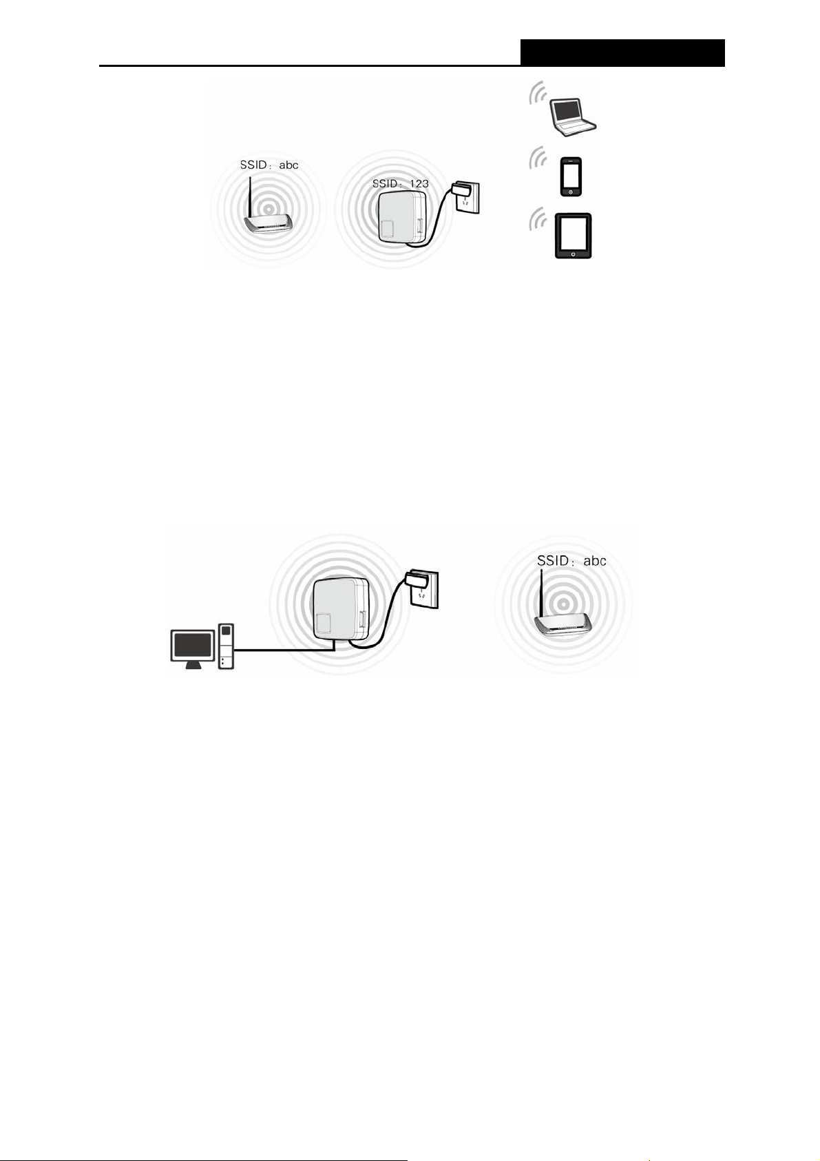
z Repeater Mode
In this mode, PW-3G401M is used to extend the range of wireless signal of the root AP.
PW-3G401M is required to set the same wireless network name (also called SSID) and wireless
security with the root AP, but the different IP addresses to avoid conflict.
1. Connect one end of the provided USB cable to mini USB port of the Router and the other
end to the power adapter, and then plug the power adapter to a standard electrical wall
socket.
2. Connect to the target remote AP or Router wirelessly.
3. Connect the notebook/PC to the Router via an Ethernet cable or wirelessly.
z Bridge with AP Mode
In this mode, PW-3G401M bridges the root AP and up to 4 APs (also in bridge mode) to connect
two or more wired LANs. Different to the repeater mode, PW-3G401M can set a different SSID
and wireless security.
-7-
Page 16
PW-3G401M 3G Wireless N Nano Router
1. Connect one end of the provided USB cable to mini USB port of the Router and the other
end to the power adapter, and then plug the power adapter to a standard electrical wall
socket.
2. Connect to the target remote AP or Router wirelessly.
3. Connect the notebook/PC to the Router via an Ethernet cable or wirelessly.
z Client Mode
In this mode, PW-3G401M acts as a wireless adapter to enable the wired host to access AP or
wireless Router. Obviously, here the LAN/WAN port is used as LAN port.
1. Connect one end of the provided USB cable to mini USB port of PW-3G401M and the other
end to the power adapter, and then plug the power adapter to a standard electrical wall
socket.
2. Connect the PC to the LAN/WAN port of the PW-3G401M via an Ethernet cable.
3. Connect PW-3G401M to the target AP or Router wirelessly.
-8-
Page 17

PW-3G401M 3G Wireless N Nano Router
Chapter 3. Quick Installation Guide
This chapter will show you how to configure the basic functions of your PW-3G401M 3G
Wireless N Nano Router using Quick Setup Wizard within minutes.
3.1 3G/4G Router Mode
The default IP address of the PW-3G401M 3G Wireless N Nano Router is 192.168.1.1 and
the default Subnet Mask is 255.255.255.0. These values can be changed as you desire. In this
guide, we all use the default values for description.
3.1.1 PC configuration
Here we take Wireless Network Connection as an example. (You can also go to Local Area
Connection to configure the PC for wired network connection, and then configure the Router. If
you need instructions as to how to do this, please refer to Appendix B: "Configuring the PC."
1. For Windows XP, please go to Start → Settings → Control Panel → Network and
Internet Connections → Network Connections; for Windows 7, please go to Start →
Settings → Control Panel → View network status and tasks → Manage network
connection. Right click Wireless Network Connection, and select Properties.
2. For Windows XP, double click Internet Protocol (TCP/IP) in the item list; for Windows 7,
double click Internet Protocol Version 4 (TCP/IPv4).
3. Select “Obtain an IP address automatically” and “Obtain DNS server address
automatically”. Click OK to finish the settings.
)
3.1.2 Connect to Network
1. Click the icon at the bottom of your desktop.
2. Click “Refresh network list”, and then select the network. Click Connect.
Note:
)
The default SSID of the network is Wireless_xxxxxx. (The xxxxxx is the last six characters of
the Router’s MAC address.)
3. When Connected appears, you’ve successfully connected to the wireless network.
3.1.3 Router Configuration
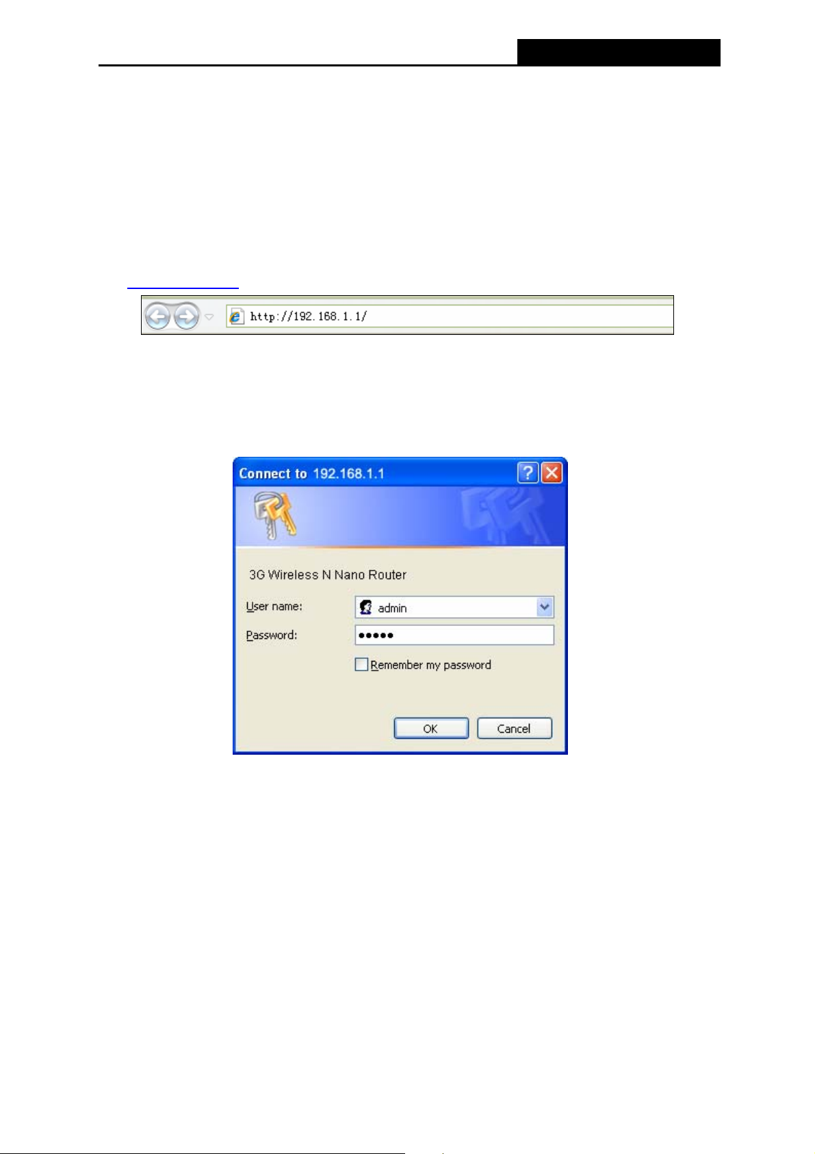
1. To access the configuration utility, open a web-browser and type the default address
http://192.168.1.1
in the address field of the browser.
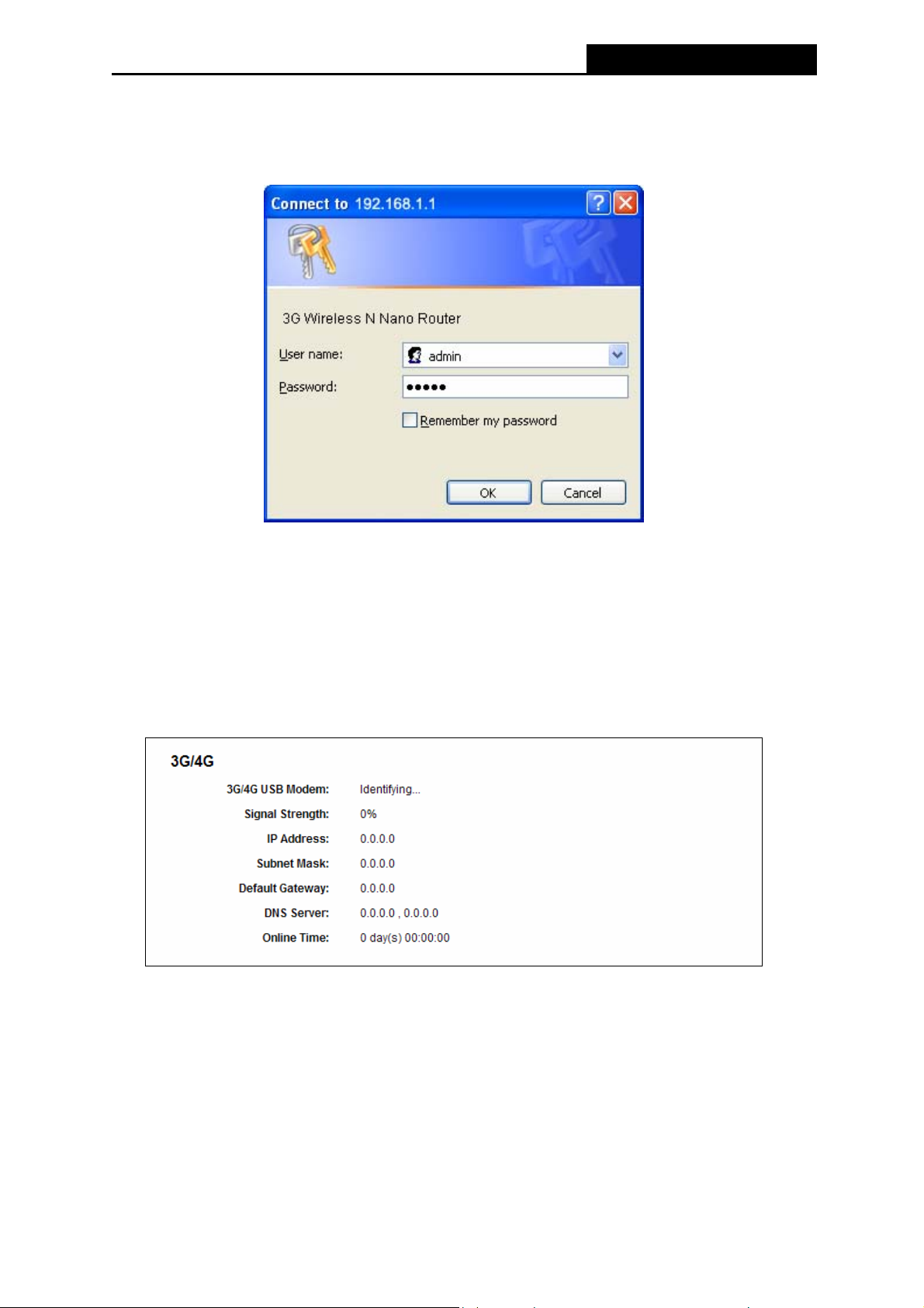
Figure 3-1 Login the Router
-9-
Page 18
PW-3G401M 3G Wireless N Nano Router
2. After a moment, a login window will appear, similar to the Figure 3-2. Enter admin for the
User Name and Password, both in lower case letters. Then click the OK button or press the
Enter key.
Figure 3-2 Login Windows
Note:
)
If the above screen does not pop-up, it means that your Web-browser has been set to a proxy.
Go to Tools menu>Internet Options>Connections>LAN Settings, in the screen that appears,
cancel the Using Proxy checkbox, and click OK to finish it.
3. Go to Status and check the 3G status. When the 3G USB modem is identified successfully,
go to the next step.
Figure 3-3 Status – 3G/4G
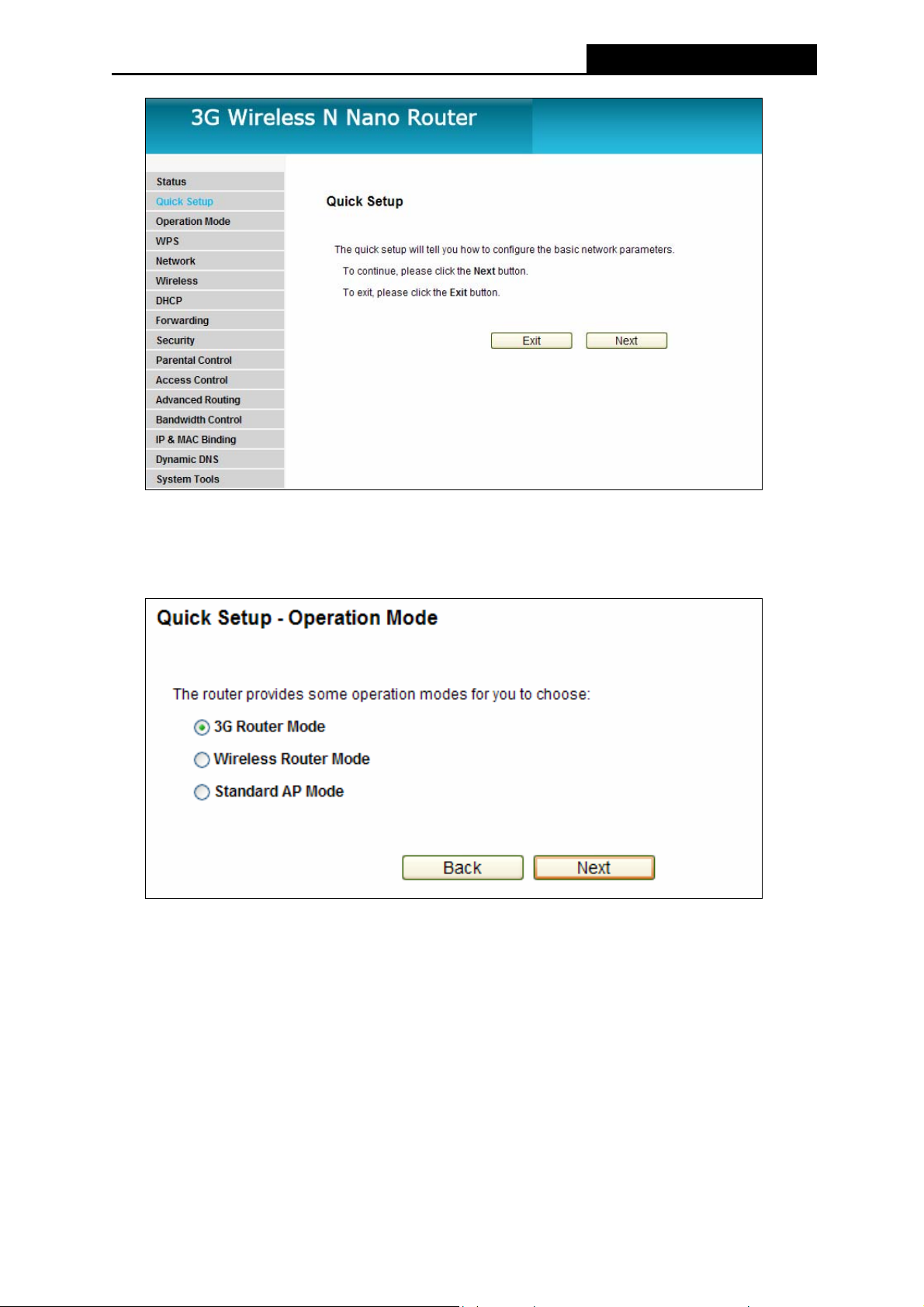
4. Click Quick Setup on the left to quickly configure your Router. Click Next.
-10-
Page 19
PW-3G401M 3G Wireless N Nano Router
Figure 3-4 Quick Setup
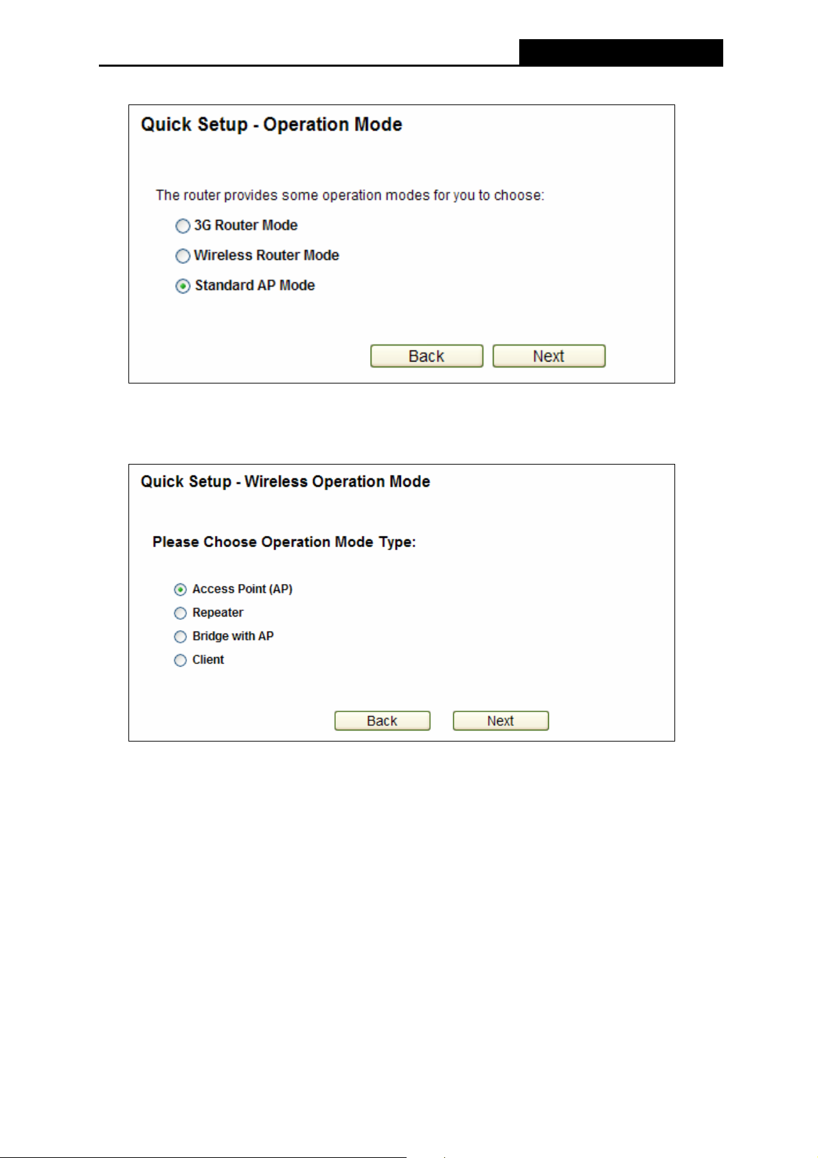
5. Choose 3G Router Mode as the operation mode and click Next.
Figure 3-5 Quick Setup – Operation Mode
¾ 3G/4G Router Mode: In this mode, the device enables multiple users to share Internet
via ADSL/Cable Modem. The wireless port share the same IP to ISP through ethernet
WAN port. The Wireless port acts the same as a LAN port while at 3G/4G Router mode.
¾ Wireless Router Mode: In this mode, the device enables multiple users to share the
Internet. The LAN devices share the same IP from ISP through Wireless port. While
connecting to ISP, the ethernet port works as a WAN port at Wireless Router mode.
¾ Standard AP Mode: In this mode, the device enables multiple users to accessing, and
provide several wireless mode. such as AP, Client, Repeater and so on.
-11-
Page 20
PW-3G401M 3G Wireless N Nano Router
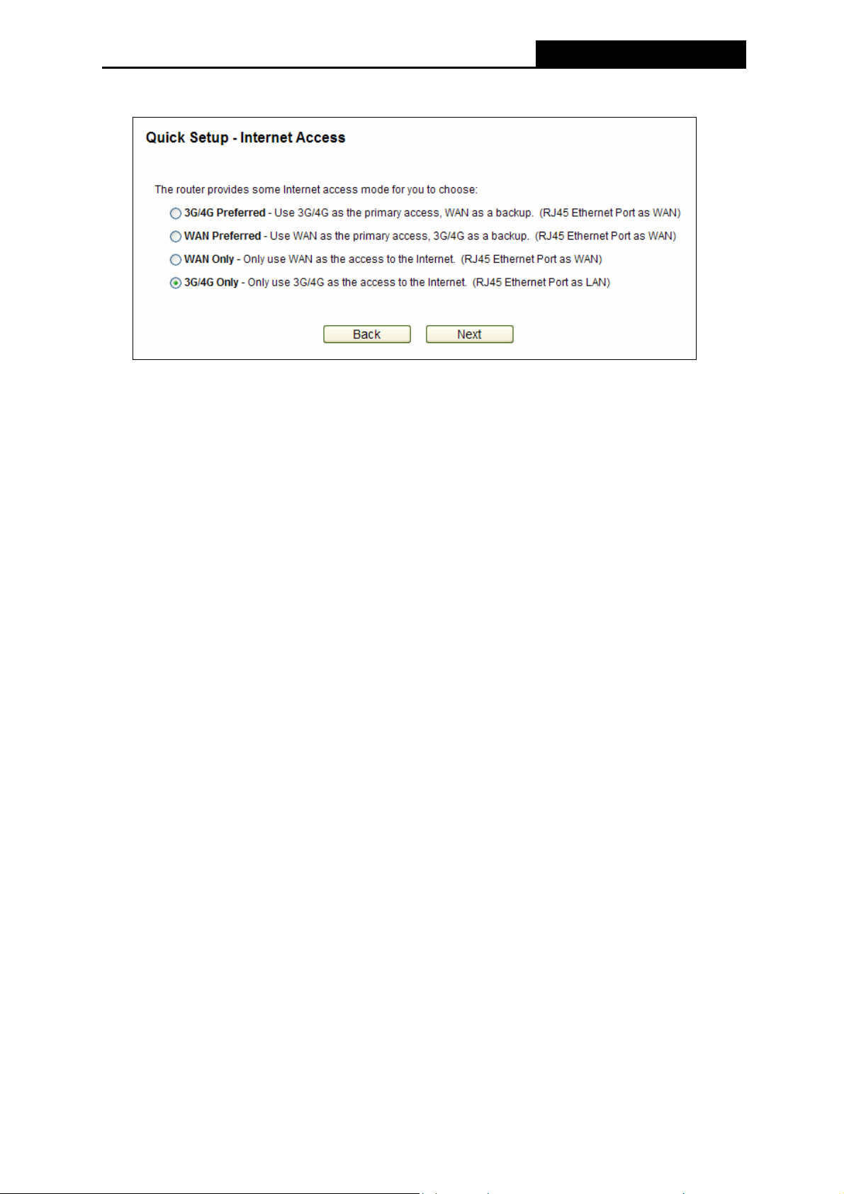
6. Select the Internet Access (here takes 3G/4G Only for example.) and click Next.
Figure 3-6 Quick Setup – Internet Access
¾ 3G/4G Preferred
In this mode, the Router will try 3G/4G access first;
When 3G/4G access fails and WAN access is valid, or when no 3G/4G USB modem is
inserted, the Router would switch to WAN access; when the Router succeeds to connect to
the 3G/4G network, the Router would stop the WAN connection and switch back to 3G/4G
access immediately.
¾ WAN Preferred
In this mode, the Router will try WAN access first;
When the WAN access fails, and 3G/4G access is valid, the Router would switch to 3G/4G
access; when the Router succeeds to connect to the WAN network, the Router would stop
the 3G/4G connection and switch back to WAN access immediately.
¾ WAN Only
In this mode, the Router will try WAN access only. 3G/4G access is disabled.
¾ 3G/4G Only
In this mode, the Router will try 3G/4G access only. WAN access is disabled and the
ethernet port acts as a LAN port.
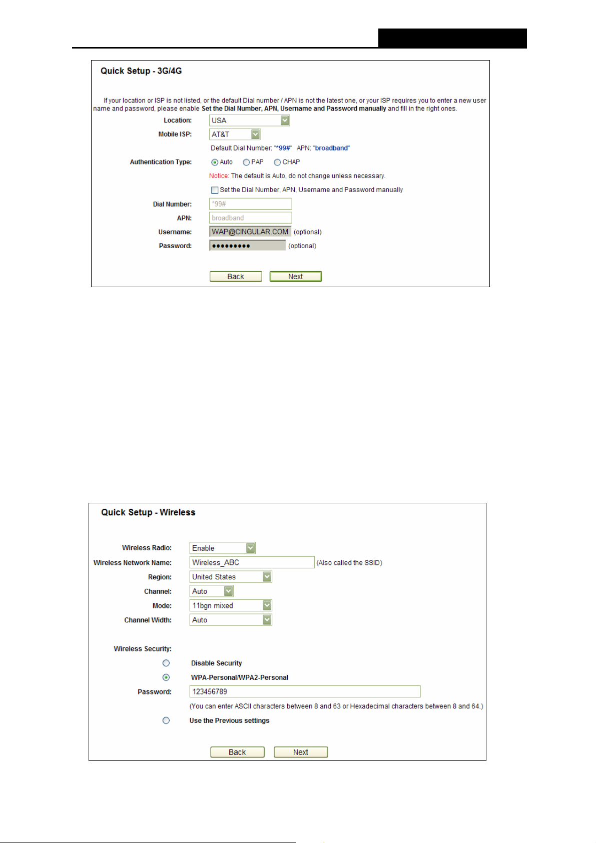
7. Select your Location and Mobile ISP, and then click Next.
If you can’t find your location and/or mobile ISP in the drop-down list, please click Set the
Dial Number, APN, Username and Password manually to manually set them according
to the information your 3G/4G ISP provided.
-12-
Page 21
PW-3G401M 3G Wireless N Nano Router
Figure 3-7 Quick Setup – 3G/4G
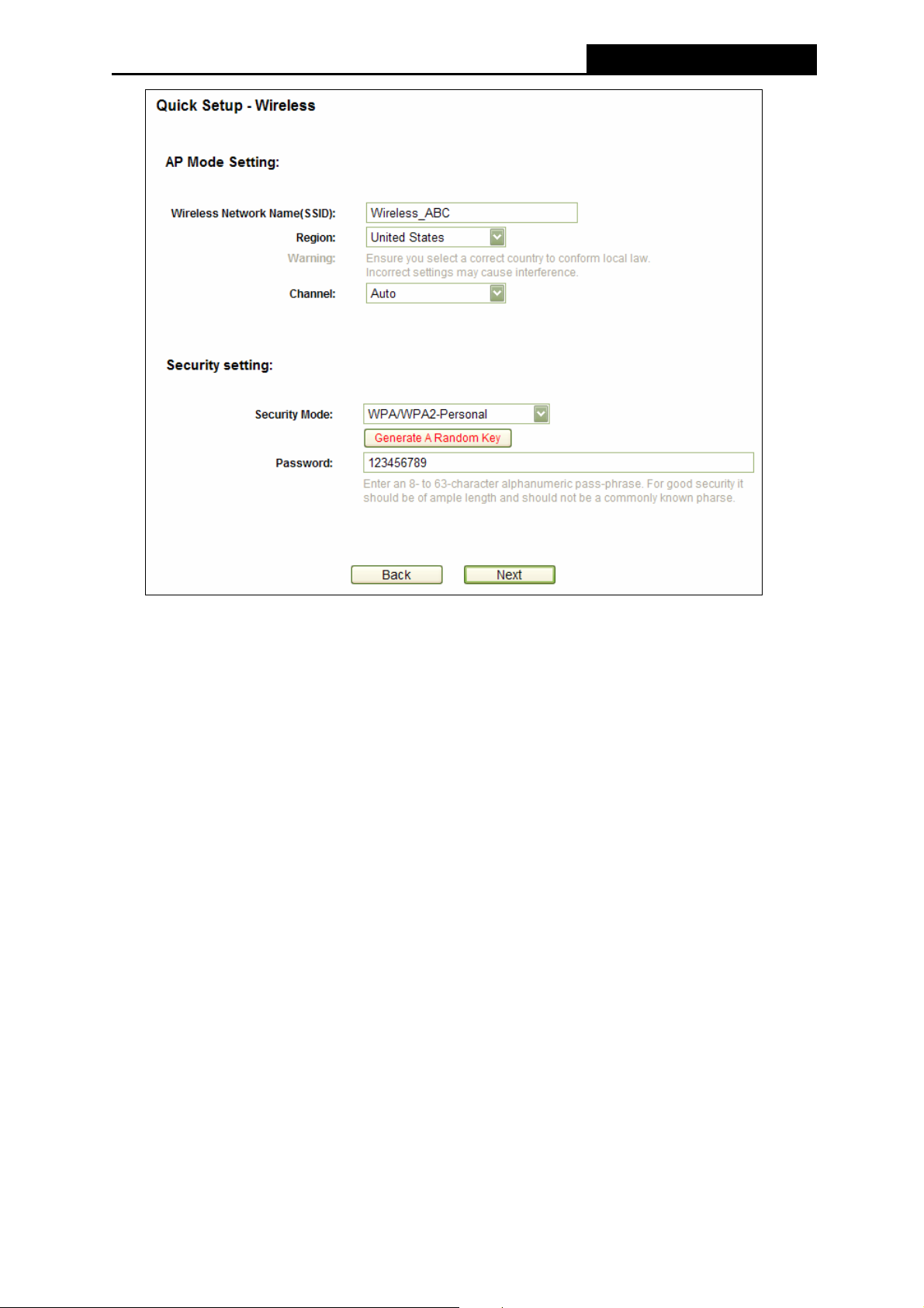
8. Set a unique and easy-to-remember Wireless Network Name, select your Region from
the drop-down-list. And it’s recommended to select WPA-Personal/WPA2-Personal as the
wireless security and set your own Password. As for other parameters, you can leave it
default. Then click Next.
Note:
Limited by the local law regulation s, version for North America does not have region selection
option selectable.
Figure 3-8 Quick Setup – Wireless
-13-
Page 22

PW-3G401M 3G Wireless N Nano Router
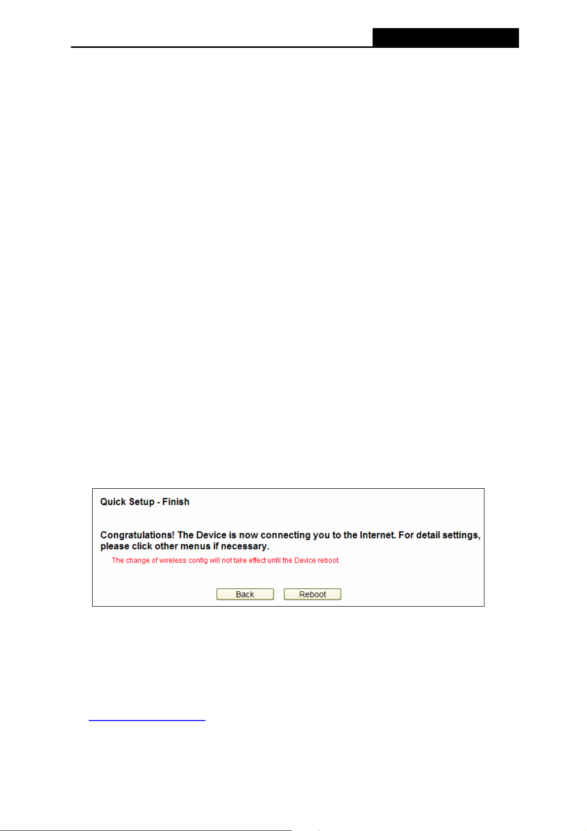
9. Click Finish/Reboot to complete the Quick Setup.
Figure 3-9 Quick Setup – Finish
Note:
)
After rebooting, please reconnect to the network (with a new SSID and Password you’ve set in
the previous step). You can refer to 3.1.2 Connect to Network
for the details.
3.2 Wireless Router Mode
The default IP address of the PW-3G401M 3G Wireless N Nano Router is 192.168.1.1 and the
default Subnet Mask is 255.255.255.0. These values can be changed as you desire. In this
guide, we all use the default values for description.
3.2.1 PC configuration
Here we take Wireless Network Connection as an example. (You can also go to Local Area
Connection to configure the PC for wired network connection, and then configure the Router. If
you need instructions as to how to do this, please refer to Appendix B: "Configuring the PC."
1. For Windows XP, please go to Start → Settings → Control Panel → Network and
Internet Connections → Network Connections; for Windows 7, please go to Start →
Settings → Control Panel → View network status and tasks → Manage network
connection. Right click Wireless Network Connection, and select Properties.
)
2. For Windows XP, double click Internet Protocol (TCP/IP) in the item list; for Windows 7,
double click Internet Protocol Version 4 (TCP/IPv4).
3. Select “Obtain an IP address automatically” and “Obtain DNS server address
automatically”. Click OK to finish the settings.
3.2.2 Connect to Network
1. Click the icon at the bottom of your desktop.
2. Click “Refresh network list”, and then select the network. Click Connect.
-14-
Page 23
PW-3G401M 3G Wireless N Nano Router
Note:
)
The default SSID of the network is Wireless_xxxxxx. (The xxxxxx is the last six characters of
the Router’s MAC address.)
3. When Connected appears, you’ve successfully connected to the wireless network.
3.2.3 Router Configuration
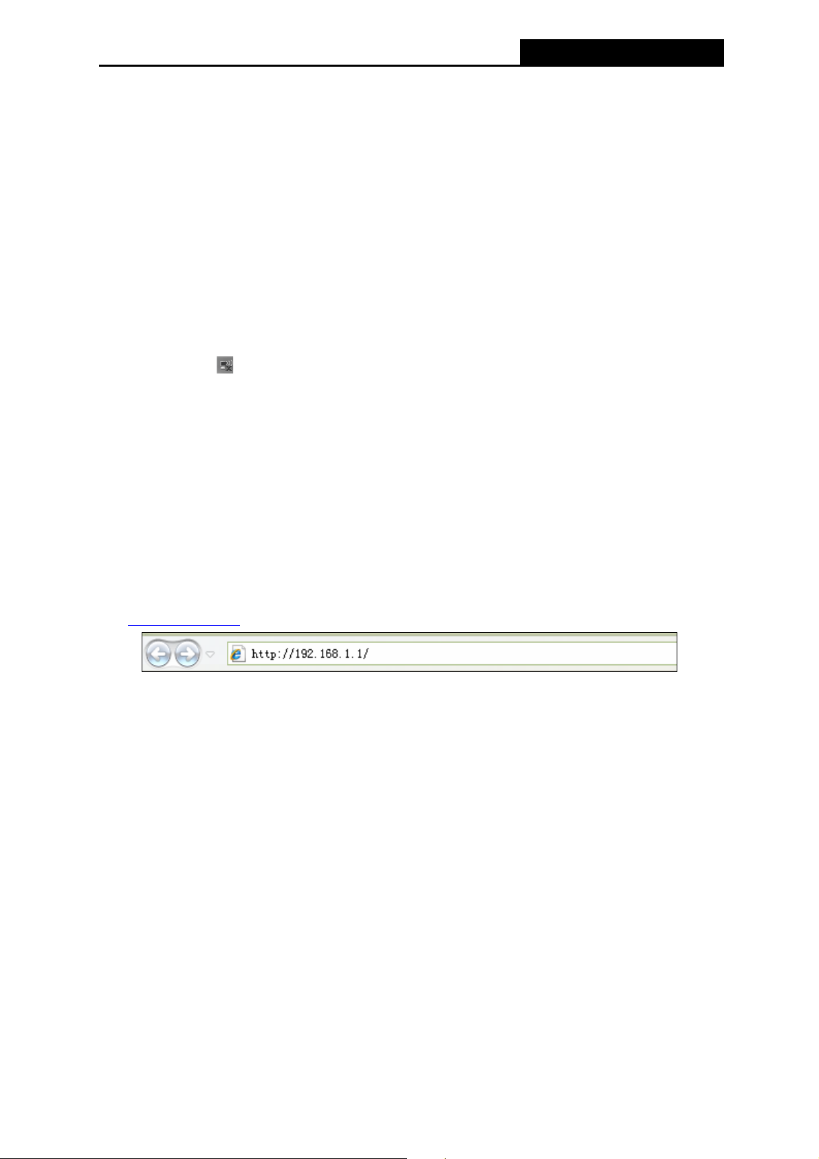
1. To access the configuration utility, open a web-browser and type the default address
http://192.168.1.1
in the address field of the browser.
Figure 3-10 Login the Router
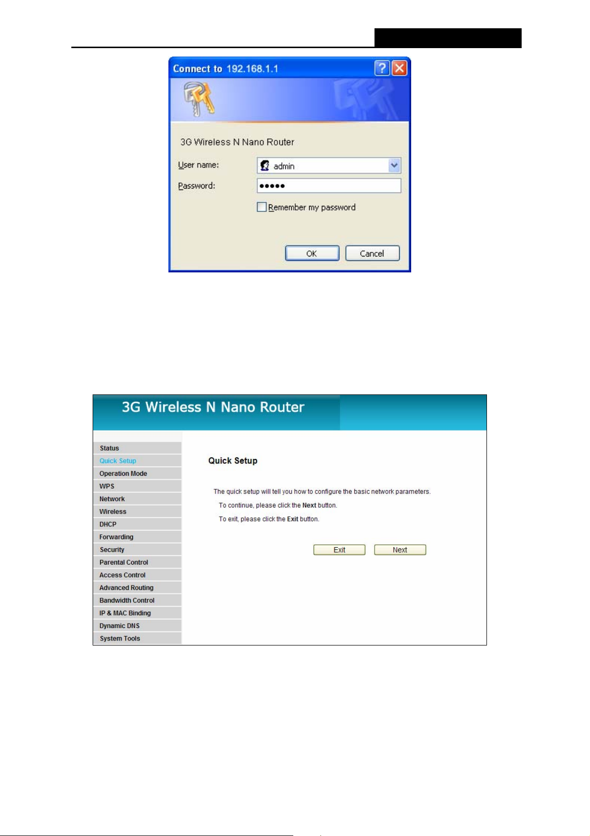
2. After a moment, a login window will appear, similar to the Figure 3-11. Enter admin for the
User Name and Password, both in lower case letters. Then click the OK button or press the
Enter key.
Figure 3-11 Login Windows
Note:
)
If the above screen does not pop-up, it means that your Web-browser has been set to a proxy.
Go to Tools menu>Internet Options>Connections>LAN Settings, in the screen that appears,
cancel the Using Proxy checkbox, and click OK to finish it.
3. Click Quick Setup on the left to quickly configure your Router. Click Next.
-15-
Page 24
PW-3G401M 3G Wireless N Nano Router
Figure 3-12 Quick Setup
4. Choose Wireless Router Mode as the operation mode and click Next.
Figure 3-13 Quick Setup – Operation Mode
-16-
Page 25
PW-3G401M 3G Wireless N Nano Router
5. Choose the WAN Connection Type and click Next.
Figure 3-14 Quick Setup – WAN Connection Type
¾ If the WAN connection type detected is PPPoE, you will be prompted to enter user name
and password provided by your ISP.
Figure 3-15 Quick Setup – PPPoE
z User Name and Password - Enter the User Name and Password provided by your
ISP. These fields are case sensitive. If you have difficulty with this process, please
contact your ISP.
z Confirm Password - Re-enter the password provided by your ISP to ensure the
Password you entered is correct. If the Password is different from the Confirm
Password, the screen will appear as shown below. Click OK, and re-enter the
Password and Confirm Password.
¾ If the WAN connection type detected is Dynamic IP, you will be prompted to set the MAC
Clone according to the situations, as described on the page below.
-17-
Page 26
PW-3G401M 3G Wireless N Nano Router
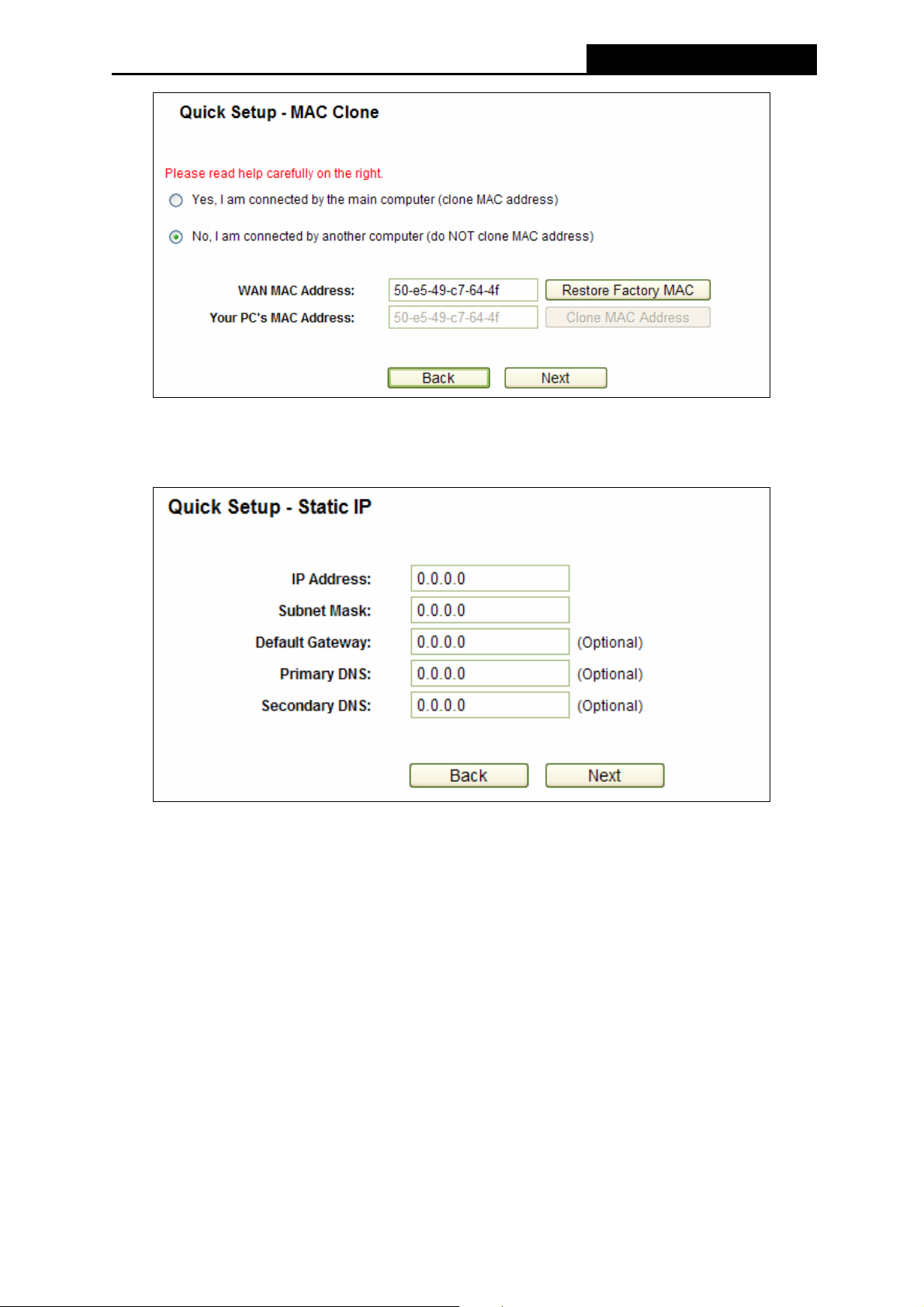
Figure 3-16 Quick Setup – MAC Clone
z If you are visiting the Router from the main computer, please select Yes, and then click
Clone MAC Address.
z If you are visiting the Router from another computer, rather than the main computer,
please select No, and then enter the main computer’s MAC in the field WAN MAC
Address.
-18-
Page 27
PW-3G401M 3G Wireless N Nano Router
¾ If the WAN connection type detected is Static IP, you will be prompted to set the necessary
parameters as IP Address, Subnet Mask, Default Gateway, Primary/Secondary DNS,
which are provided by your ISP.
Figure 3-17 Quick Setup - Static IP
z IP Address - This is the WAN IP address seen by external users on the Internet
(including your ISP). Enter the IP address into the field.
z Subnet Mask - The Subnet Mask is used for the WAN IP address, it is usually
255.255.255.0.
z Default Gateway - Enter the gateway IP address into the box if required.
z Primary DNS - Enter the DNS Server IP address into the box if required.
z Secondary DNS - If your ISP provides another DNS server, enter it into this field.
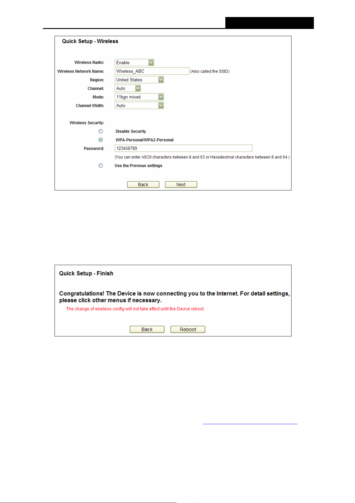
6. Set a unique and easy-to-remember Wireless Network Name, select your Region from
the drop-down-list. And it’s recommended to select WPA-Personal/WPA2-Personal as the
wireless security and set your own Password. As for other parameters, you can leave it
default. Then click Next.
-19-
Page 28
PW-3G401M 3G Wireless N Nano Router
Figure 3-18 Quick Setup – Wireless
Note:
Limited by the local law regulation s, version for North America does not have region selection
option selectable.
7. Click Finish/Reboot to complete the Quick Setup.
Figure 3-19 Quick Setup – Finish
3.3 Standard AP Mode
3.3.1 PC configuration
Here we take Wireless Network Connection as an example. (You can also go to Local Area
Connection to configure the PC for wired network connection, and then configure the Router. If
you need instructions as to how to do this, please refer to Appendix B: "Configuring the PC."
1. For Windows XP, please go to Start → Settings → Control Panel → Network and
Internet Connections → Network Connections; for Windows 7, please go to Start →
Settings → Control Panel → View network status and tasks → Manage network
-20-
)
Page 29
PW-3G401M 3G Wireless N Nano Router
connection. Right click Wireless Network Connection, and select Properties.
2. For Windows XP, double click Internet Protocol (TCP/IP) in the item list; for Windows 7,
double click Internet Protocol Version 4 (TCP/IPv4).
3. Select “Use the following IP address”, enter the 192.168.0.x as the IP address (x can be
any number from 1 to 253), 255.255.255.0 as the Subnet mask; select “Use the following
DNS server addresses”, enter the DNS server address provided by your ISP or network
administrator.
4. Click OK to finish the settings.
3.3.2 Connect to Network
1. Click the icon at the bottom of your desktop.
2. Click “Refresh network list”, and then select the network. Click Connect.
Note:
)
The default SSID of the network is Wireless_xxxxxx. (The xxxxxx is the last six characters of
the Router’s MAC address.)
3. When Connected appears, you’ve successfully connected to the wireless network.
3.3.3 Router Configuration
1. To access the configuration utility, open a web-browser and type the default address
http://192.168.1.1
in the address field of the browser.
Figure 3-20 Login the Router
2. After a moment, a login window will appear, similar to the Figure 3-21. Enter admin for the
User Name and Password, both in lower case letters. Then click the OK button or press the
Enter key.
-21-
Page 30
PW-3G401M 3G Wireless N Nano Router
Figure 3-21 Login Windows
Note:
)
If the above screen does not pop-up, it means that your Web-browser has been set to a proxy.
Go to Tools menu>Internet Options>Connections>LAN Settings, in the screen that appears,
cancel the Using Proxy checkbox, and click OK to finish it.
3. Click Quick Setup on the left to quickly configure your Router. Click Next.
Figure 3-22 Quick Setup
-22-
Page 31
PW-3G401M 3G Wireless N Nano Router
4. Choose Standard AP Mode as the operation mode and click Next.
Figure 3-23 Operation Mode
5. Choose Wireless Operation Mode according to your need, and click Next.
Figure 3-24 Quick Setup – Wireless Operation Mode
¾ If Access Point is selected, you will be prompted the below page to set the Wireless
Network Name(SSID), Region, Security Mode and Password. Click Next to proceed.
-23-
Page 32
PW-3G401M 3G Wireless N Nano Router
Figure 3-25 Quick Setup – AP
z Wireless Network Name (SSID) - Enter a string of up to 32 characters. The same
Name (SSID) must be assigned to all wireless devices in your network. The default
SSID is set to be Wireless_xxxxxx (xxxxxx indicates the last unique six characters of
each Router's MAC address), which can ensure your wireless network security. But it
is recommended strongly that you change your networks name (SSID) to a different
value. This value is case-sensitive. For example, MYSSID is NOT the same as
MySsid.
z Region - Select your region from the pull-down list. This field specifies the region
where the wireless function of the Router can be used. It may be illegal to use the
wireless function of the Router in a region other than one of those specified in this
filed. If your country or region is not listed, please contact your local government
agency for assistance.
z Channel - This field determines which operating frequency will be used. It is not
necessary to change the wireless channel unless you notice interference problems
with another nearby access point. If you select auto, then the AP will select the best
channel automatically.
¾ If Repeater is selected, you will be prompted the below page. Click Survey to search
and Connect your target remote AP, select your region, and set your security mode
as well as password which are the same as the root AP you’ve connected.
-24-
Page 33

PW-3G401M 3G Wireless N Nano Router
Figure 3-26 Quick Setup – Repeater
z Name of remote AP (SSID) - Enter the name of a remote AP (also called the SSID)
that you want to access. Click the Survey button behind it, you can choose one of
searching results to fill in this field.
z MAC Address - Enter the MAC address of AP that you want to access. When you
use the survey function to fulfill the Name of remote AP (SSID), this field will be filled
in automatically.
z Region - This field determines which operating frequency will be used. To achieve
more information, you can read the same glossary in Access Point part.
¾ If Bridge with AP is selected, you will be prompted the below page. Set a unique and
easy-to-remember wireless network name (SSID), select your region. Click Survey to
search and Connect your target remote AP(s). Set your wireless security, where you
can select Use the Previous Settings to keep the same with the remote AP(s) you’ve
connected, or set a different one.
-25-
Page 34

PW-3G401M 3G Wireless N Nano Router
Figure 3-27 Quick Setup – Bridge with AP
z Wireless Network Name (SSID) - Enter a string of up to 32 characters. To achieve
more information, you can read the same glossary in Access Point part.
z Region - This field determines which operating frequency will be used. To achieve
more information, you can read the same glossary in Access Point part.
z Channel - This field determines which operating frequency will be used. To achieve
more information, you can read the same glossary in Access Point part.
z Add a remote AP - Click the Survey button to fill in the MAC of remote AP (1-4) field.
z MAC of remote AP (1-4) - Enter the MAC address of AP that you want to access.
¾ If Client is selected, you will be prompted the below page. Click Survey to search and
Connect your target AP, and set your security mode as well as password.
-26-
Page 35

PW-3G401M 3G Wireless N Nano Router
Figure 3-28 Quick Setup – Client
z None - The wireless security function can be enabled or disabled. If you select "None",
the wireless stations will be able to connect the Router without encryption. It is
recommended strongly that you choose one of following options to enable security.
z WEP
Type - You can select one of following types:
Automatic - Select Shared Key or Open System authentication type automatically
based on the wireless station's capability and request.
Open System - Select 802.11 Open System authentication.
Shared Key - Select 802.11 Shared Key authentication.
WEP Key Format - You can select ASCII or Hexadecimal format. ASCII Format
stands for any combination of keyboard characters in the specified length.
Hexadecimal format stands for any combination of hexadecimal digits (0-9, a-f, A-F)
in the specified length.
WEP Key settings - Select which of the four keys will be used and enter the matching
WEP key information for your network in the selected key radio button. These values
must be identical on all wireless stations in your network.
Key Type - You can select the WEP key length (64-bit, or 128-bit, or 152-bit.) for
encryption. “Disabled" means this WEP key entry is invalid.
-27-
Page 36
PW-3G401M 3G Wireless N Nano Router
For 64-bit encryption - You can enter 10 hexadecimal digits (any combination of 0-9,
a-f, A-F, and null key is not permitted) or 5 ASCII characters.
For 128-bit encryption - You can enter 26 hexadecimal digits (any combination of 0-9,
a-f, A-F, and null key is not permitted) or 13 ASCII characters.
For 152-bit encryption - You can enter 32 hexadecimal digits (any combination of 0-9,
a-f, A-F, and null key is not permitted) or 16 ASCII characters.
z WPA/WPA2-Personal
Version - You can select one of following versions:
Automatic - Select WPA-Personal or WPA2-Personal automatically based on the
wireless station's capability and request.
WPA-Personal - Pre-shared key of WPA.
WPA2-Personal - Pre-shared key of WPA2.
Encryption - You can select either Automatic, or TKIP or AES.
Password - You can enter ASCII or Hexadecimal characters. For Hexadecimal, the
length should be between 8 and 64 characters; for ASCII, the length should be
between 8 and 63 characters.
Group Key Update Period - Specify the group key update interval in seconds. The
value can be either 0 or at least 30. Enter 0 to disable the update.
z Not Change - If you chose this option, wireless security configuration will not change!
6. Click Finish/Reboot to complete the Quick Setup.
Figure 3-29 Quick Setup – Finish
Note:
)
z In Access Point/ Repeater/ Bridge with AP Mode, after rebooting, please reconnect to the
network (with a new SSID and Password you’ve set in the previous step). You can refer to
3.3.2 Connect to Network for the details.
z If you have any difficulty with these steps, please refer to the User Guide on the Resource
CD for detailed instructions.
-28-
Page 37
PW-3G401M 3G Wireless N Nano Router
Chapter 4. Router Configuration – 3G Router Mode
This chapter will show each Web page's key functions and the configuration way on 3G/4G
Router Mode.
4.1 Login
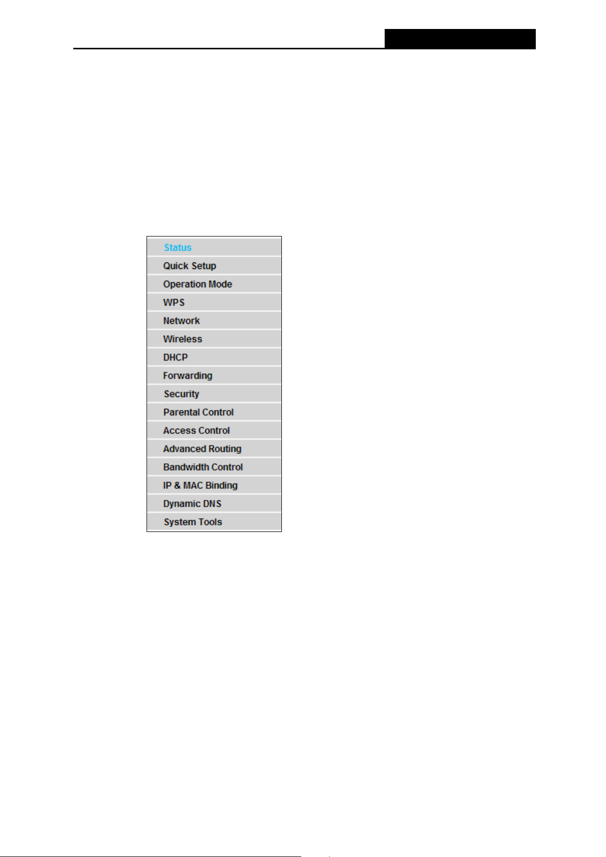
After your successful login, you will see the main menus on the left of the Web-based utility. On
the right, there are the corresponding explanations and instructions.
The detailed explanations for each Web page’s key function are listed below.
4.2 Status
The Status page provides the current status information about the Router. All information is
read-only.
-29-
Page 38
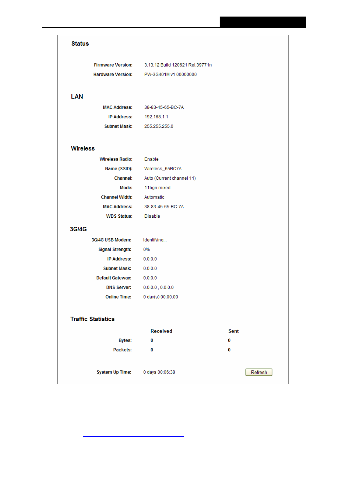
PW-3G401M 3G Wireless N Nano Router
Figure 4-1 Router Status
4.3 Quick Setup
Please refer to Chapter 3: "Quick Installation Guide."
-30-
Page 39

PW-3G401M 3G Wireless N Nano Router
4.4 Operation Mode
Choose menu “Operation Mode”, and you can see three operation modes of the Router as
shown below.
Figure 4-2 Operation Mode
¾ 3G/4G Router Mode - In this mode, the device enables multiple users to share Internet via
ADSL/Cable Modem. The wireless port share the same IP to ISP through ethernet WAN
port. The Wireless port acts the same as a LAN port while at 3G/4G Router mode.
¾ Wireless Router Mode - In this mode, the device enables multiple users to share the
Internet. The LAN devices share the same IP from ISP through Wireless port. While
connecting to ISP, the ethernet port works as a WAN port at Wireless Router mode.
¾ Standard AP Mode - In this mode, the device enables multiple users to accessing and
provides several wireless modes, such as AP, Client, Repeater and so on.
Note:
)
The Router will reboot automatically after you click the Save button.
4.5 WPS
This section will guide you add a new wireless device to an existing network quickly by WPS
(Wi-Fi Protected Setup) function.
a). Choose menu “WPS”, and you will see the next screen (shown in Figure 4-3 ).
-31-
Page 40

PW-3G401M 3G Wireless N Nano Router
Figure 4-3 WPS
¾ WPS Status - Enable or disable the WPS function here.
¾ Current PIN - The current value of the Router's PIN displayed here. The default PIN of the
Router can be found in the label or User Guide.
¾ Restore PIN - Restore the PIN of the Router to its default.
¾ Gen New PIN - Click this button, and then you can get a new random value for the
Router's PIN. You can ensure the network security by generating a new PIN.
¾ Disable PIN of this Device - WPS external registrar of entering the device's PIN can be
disabled or enabled manually. If the device receives multiple failed attempts to
authenticate an external Registrar, this function will be disabled automatically.
¾ Add device - You can add the new device to the existing network manually by clicking this
button.
b). To add a new device:
If the wireless adapter supports Wi-Fi Protected Setup (WPS), you can establish a wireless
connection between wireless adapter and Router using either Push Button Configuration (PBC)
method or PIN method.
Note:
)
To build a successful connection by WPS, you should also do the corresponding configuration
of the new device for WPS function meanwhile.
For the configuration of the new device, here takes the Wireless Adapter of our company for
example.
I. By PBC
If the wireless adapter supports Wi-Fi Protected Setup and the Push Button Configuration (PBC)
method, you can add it to the network by PBC with the following two methods.
Method One:
Step 1: Click the Enable WPS button to trigger the WPS function in Figure 4-3, and click the
Add device button in Figure 4-3, then the following screen will appear.
-32-
Page 41

PW-3G401M 3G Wireless N Nano Router
Figure 4-4 Add A New Device
Step 2: Choose Press the button of the new device in two minutes and click Connect.
Step 3: For the configuration of the wireless adapter, please choose Push the button on my
access point in the configuration utility of the WPS as below, and click Next.
The WPS Configuration Screen of Wireless Adapter
Step 4: Wait for a while until the next screen appears. Click Finish to complete the WPS
configuration.
-33-
Page 42
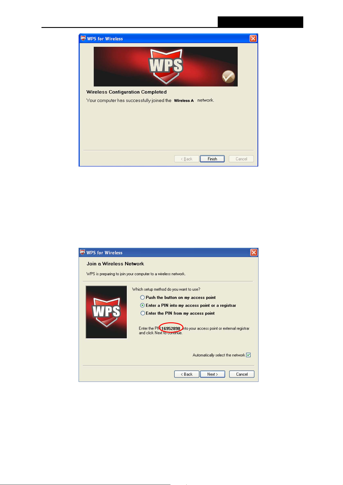
II. By PIN
PW-3G401M 3G Wireless N Nano Router
The WPS Configuration Screen of Wireless Adapter
If the new device supports Wi-Fi Protected Setup and the PIN method, you can add it to the
network by PIN with the following two methods.
Method One: Enter the PIN into my Router
Step 1: Configure the wireless adapter. Please choose Enter a PIN into my access point or a
registrar in the configuration utility of the WPS as below, and click Next.
The WPS Configuration Screen of wireless adapter
Note:
)
In this example, the default PIN code of this adapter is 16952898 as the above figure shown.
Step 2: Configure the Router. Keep the default WPS Status as Enabled and click the Add
device button in
Figure 4-3, then the following screen will appear.
-34-
Page 43
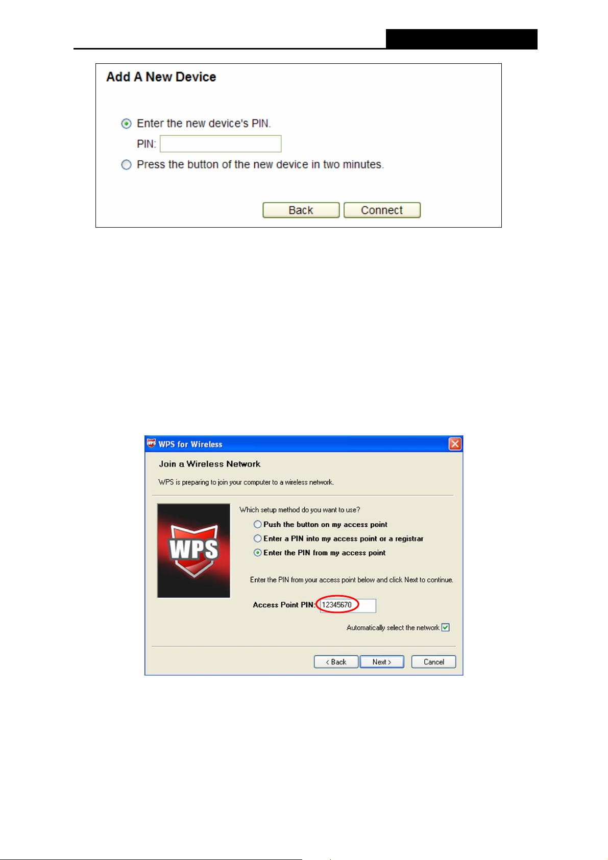
PW-3G401M 3G Wireless N Nano Router
Step 3: Choose Enter the new device's PIN and enter the PIN code of the wireless adapter in
the field behind PIN in the previous figure. Then click Connect.
Note:
)
The PIN code of the wireless adapter is always displayed on the WPS or WPS configuration
screen.
Method Two: Enter the PIN from my Router
Step 1: Get the Current PIN code of the Router in
code. Here takes the PIN code 12345670 of this Router for example).
Step 2: For the configuration of the wireless adapter, please choose Enter a PIN from my
access point in the configuration utility of the WPS as below, and enter the PIN code
of the Router into the field behind Access Point PIN. Then click Next.
Figure 4-3 (each Router has its unique PIN
The WPS Configuration Screen of Wireless adapter
Note:
)
The default PIN code of the Router can be found in its label or the WPS configuration screen as
Figure 4-3.
-35-
Page 44

PW-3G401M 3G Wireless N Nano Router
c). You will see the following screen when the new device successfully connected to the
network.
Note:
)
1) The status LED on the Router will light green all the time if the device has been
successfully added to the network.
2) The WPS function cannot be configured if the Wireless Function of the Router is disabled.
Please make sure the Wireless Function is enabled before configuring the WPS.
4.6 Network
Figure 4-5 the Network menu
There are five submenus under the Network menu (shown in Figure 4-5): Internet Access,
3G/4G, WAN, MAC Clone and LAN. Click any of them, and you will be able to configure the
corresponding function.
4.6.1 Internet Access
Choose menu “Network→Internet Access”, you can configure the access mode on the screen
below. The Router is designed to work with either WAN port or 3G/4G USB modem, and
supports automatically take over back up with 3G/4G access as Ethernet WAN failover.
-36-
Page 45

PW-3G401M 3G Wireless N Nano Router
Figure 4-6 Internet Access Mode
¾ 3G/4G Preferred
In this mode, the Router will try 3G/4G access first. When 3G/4G access fails and WAN
access is valid, or when no 3G/4G USB modem is inserted, the Router would switch to
WAN access; when the Router succeeds to connect to the 3G/4G network, the Router
would stop the WAN connection and switch back to 3G/4G access immediately.
¾ WAN Preferred
In this mode, the Router will try WAN access first. When the WAN access fails, and 3G/4G
access is valid, the Router would switch to 3G/4G access; when the Router succeeds to
connect to the WAN network, the Router would stop the 3G/4G connection and switch back
to WAN access immediately.
¾ WAN Only
In this mode, the Router will try WAN access only. 3G/4G access is disabled.
¾ 3G/4G Only
In this mode, the Router will try 3G/4G access only. WAN access is disabled.
Click the Save button to save your settings.
Note:
)
1) In 3G/4G preferred and WAN preferred modes, until 2010-5-18, the failover/backup function
only works between 3G/4G link and PPPoE / Dynamic IP / Static IP.
The failover/backup feature between 3G/4G link and BigPond Cable / PPTP / L2TP will be
available in the near future. Please visit our website to download the latest firmware.
2) If you are using the 3G/4G Preferred or WAN Preferred, the Router would connect,
disconnect or switch the current access automatically. The Connect/Disconnect button (on
3G/4G, PPPoE, PPTP, L2TP) and some related parameters could not be set manually.
4.6.2 3G/4G
Choose menu “Network→3G/4G”, you can configure parameters for 3G/4G function on the
-37-
Page 46
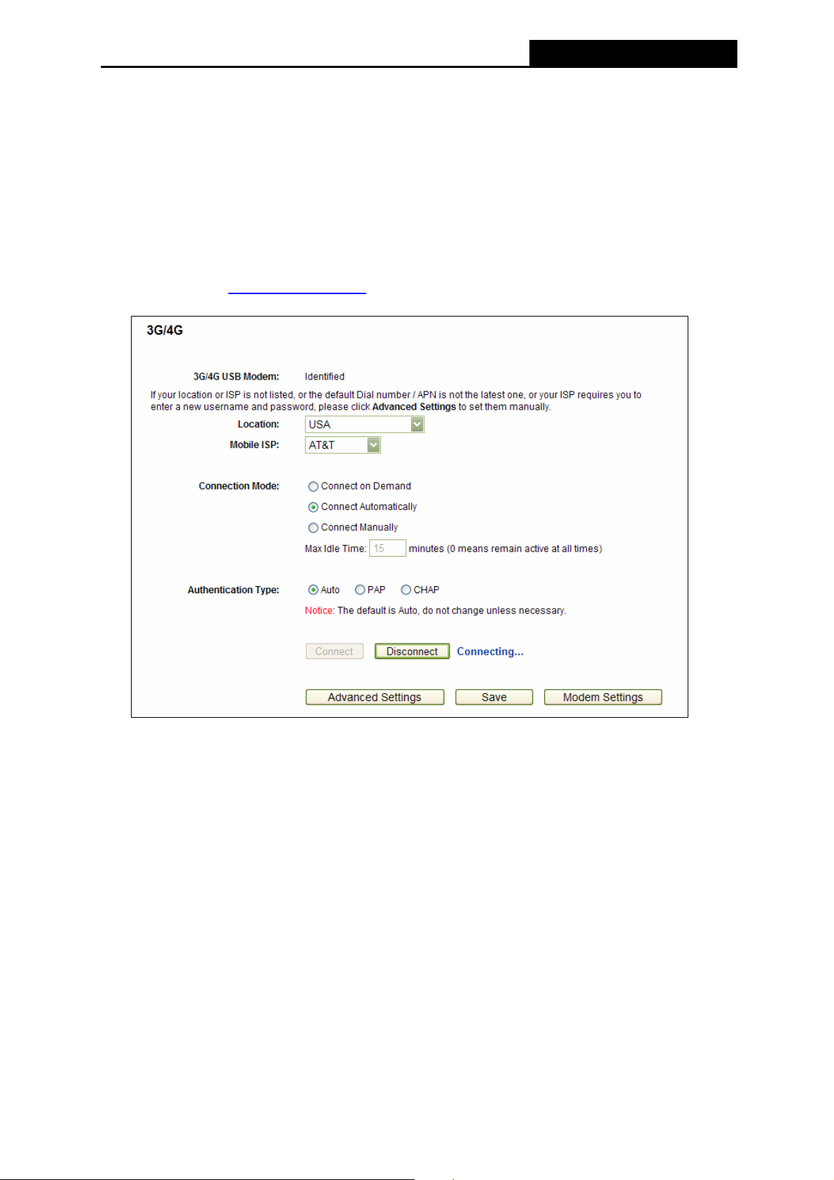
PW-3G401M 3G Wireless N Nano Router
screen below. To use the 3G/4G function, you should first insert your USB modem on the USB
port of the Router. There is already much 3G/4G USB modem information embedded in the
Router. The USB modem parameters will be set automatically if the card is supported by the
Router. Take MA180 for example. If your USB modem inserted is supported by the Router, click
Advanced Settings in Figure 4-7.
Note:
)
3G/4G settings are unavailable when the Internet Access mode is set to WAN Only mode. Please
change settings on 4.6.1 Internet Access
if you want to use 3G/4G.
Figure 4-7 3G/4G
¾ Location - Please select the location where you're enjoying the 3G/4G card.
¾ Mobile ISP - Please select the ISP (Internet Service Provider) you apply to for 3G/4G
service. The Router will show the default Dial Number and APN of that ISP.
¾ Connect on Demand - You can configure the Router to disconnect your Internet
connection after a specified period of the Internet connectivity (Max Idle Time). If your
Internet connection has been terminated due to inactivity, Connect on Demand enables
the Router to automatically re-establish your connection as soon as you attempt to access
the Internet again. If you wish to activate Connect on Demand, click the radio button. If you
want your Internet connection to remain active at all times, enter 0 in the Max Idle Time
field. Otherwise, enter the number of minutes you want to have elapsed before your Internet
connection terminates.
-38-
Page 47

PW-3G401M 3G Wireless N Nano Router
Note:
)
Sometimes the connection cannot be disconnected although you specify a time to Max Idle
Time because some applications visit the Internet continually in the background.
¾ Connect Automatically - Connect automatically after the Router is disconnected. To use
this option, click the radio button.
¾ Connect Manually - You can configure the Router to make it connect or disconnect
manually. After a specified period of inactivity (Max Idle Time), the Router will disconnect
your Internet connection, and not be able to re-establish your connection automatically as
soon as you attempt to access the Internet again. To use this option, click the radio button.
If you want your Internet connection to remain active at all times, enter 0 in the Max Idle
Time field. Otherwise, enter the number in minutes that you wish to have the Internet
connecting last unless a new link requested.
Note:
)
Sometimes the connection cannot be disconnected although you specify a time to Max Idle
Time because some applications visit the Internet continually in the background.
¾ Authentication Type - Some ISPs need a specific authentication type, please confirm it
with your ISP or keep it Auto.
z Auto-The Router will have dynamic negotiation with the dialing server and the
Autnentication Type need not to be specified. The default type is Auto.
z PAP-Password Authentication Protocol. This protocol allows the Router to establish
authentication with the peer using two handshakes. Select this option if the ISP requires
this authentication type.
z CHAP-Challenge Handshake Authentication Protocol. This protocol allows the route to
establish authentication with the peer using three handshakes and checking the peer
identity periodically. Select this option if the ISP requires this authentication type.
Click the Advanced Settings button to set up the advanced options in the screen as shown in
Figure 4-8.
-39-
Page 48

PW-3G401M 3G Wireless N Nano Router
Figure 4-8 3G/4G Advanced Settings
¾ Location / Mobile ISP – These two fields will display the location and the ISP you have
selected in the previous page (shown in Figure 4-7). While you tick the below option Set the
Dial Number and APN manually, there will be no specific information in these two fields.
¾ Set the Dial Number and APN manually - Tick the checkbox and then you are able to fill in
the Dial Number and APN blanks below, if your ISP is not listed in the Mobile ISP field in the
previous page (Figure 4-7).
¾ Dial Number - Enter the Dial Number provided by your ISP.
¾ APN - Enter the APN (Access Point Name) provided by your ISP.
¾ Username/Password - Enter the User Name and Password provided by your ISP. These
fields are case-sensitive.
¾ MTU Size - The default MTU (Maximum Transmission Unit) size is 1480 bytes, which is
usually fine. For some ISPs, you need modify the MTU. This should not be done unless
you are sure it is necessary for your ISP.
¾ Use the following DNS Servers - If your ISP specify a DNS server IP address for you,
click the checkbox, and fill the Primary DNS and Secondary DNS blanks below. The
Secondary DNS is optional. Otherwise, the DNS servers will be assigned dynamically from
ISP.
¾ Primary DNS - (Optional) Enter the DNS IP address in dotted-decimal notation provided by
your ISP.
¾ Secondary DNS - (Optional) Enter another DNS IP address in dotted-decimal notation
provided by your ISP.
-40-
Page 49

PW-3G401M 3G Wireless N Nano Router
Click the Save button to save your settings.
Click the Back button to return the previous page.
Click the Modem Settings button (in Figure 4-7) if your 3G/4G USB Modem is not supported by
the Router, and then you will see the screen as shown in Figure 4-9. Parameters of your USB
modem can be configured on this page.
Figure 4-9 3G/4G USB Modem Settings
There is already much 3G/4G USB modem information embedded in the Router. The USB
modem parameters will be set automatically if the card is supported by the Router. But when
the Router finds the card you just insert "unknown" to it, it will prompt you to set these
parameters. The Router can identify your "unknown" card if the correct parameters are in the
list. We suggest you to do the “3G/4G USB Modem Setting” only in such circumstance.
To add 3G/4G USB Modem entries, follow the steps below.
1. Download a most recent 3G/4G USB modem configuration file from our website.
2. Click the Add New... button in Figure 4-9, and then you will see Figure 4-10.
3. Click Browse… to select the path name where you save the downloaded file on the
computer into the File blank.
4. Click the Upload button to upload the configuration.
Figure 4-10 Add or Modify a 3G/4G USB Modem Entry
4.6.3 WAN
Choose menu “Network→WAN”, you can configure the IP parameters of the WAN on the
screen below.
Note:
)
WAN settings are unavailable when the Internet Access mode is set to 3G/4G Only mode. Please
change settings on 4.6.1 Internet Access
if you want to use WAN.
-41-
Page 50

PW-3G401M 3G Wireless N Nano Router
1. If your ISP provides the DHCP service, please choose Dynamic IP type, and the Router
will automatically get IP parameters from your ISP. You can see the page as follows
(Figure 4-11):
Figure 4-11 WAN - Dynamic IP
This page displays the WAN IP parameters assigned dynamically by your ISP, including IP
address, Subnet Mask, Default Gateway, etc. Click the Renew button to renew the IP
parameters from your ISP. Click the Release button to release the IP parameters.
¾ MTU Size - The normal MTU (Maximum Transmission Unit) value for most Ethernet
networks is 1500 Bytes. It is not recommended that you change the default MTU Size
unless required by your ISP.
¾ Use These DNS Servers - If your ISP gives you one or two DNS addresses, select Use
These DNS Servers and enter the primary and secondary addresses into the correct fields.
Otherwise, the DNS servers will be assigned dynamically from your ISP.
Note:
)
If you get Address not found error when you access a Web site, it is likely that your DNS
servers are set up improperly. You should contact your ISP to get DNS server addresses.
¾ Host Name - This option specifies the Host Name of the Router.
-42-
Page 51
PW-3G401M 3G Wireless N Nano Router
¾ Get IP with Unicast DHCP - A few ISPs' DHCP servers do not support the broadcast
applications. If you cannot get the IP Address normally, you can choose this option. (It is
rarely required.)
2. If your ISP provides a static or fixed IP Address, Subnet Mask, Gateway and DNS setting,
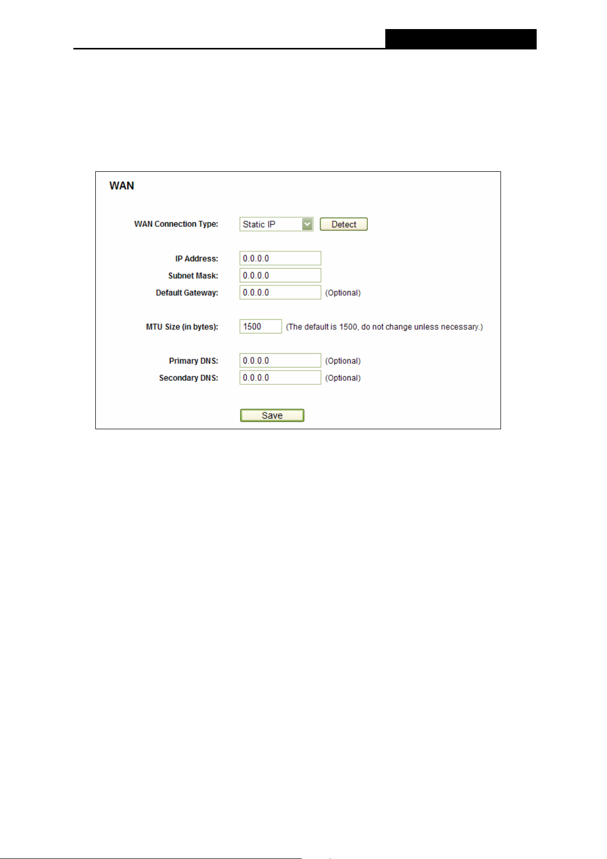
select Static IP. The Static IP settings page will appear, shown in Figure 4-12.
Figure 4-12 WAN - Static IP
¾ IP Address - Enter the IP address in dotted-decimal notation provided by your ISP.
¾ Subnet Mask - Enter the subnet Mask in dotted-decimal notation provided by your ISP,
usually is 255.255.255.0.
¾ Default Gateway - (Optional) Enter the gateway IP address in dotted-decimal notation
provided by your ISP.
¾ MTU Size - The normal MTU (Maximum Transmission Unit) value for most Ethernet
networks is 1500 Bytes. It is not recommended that you change the default MTU Size
unless required by your ISP.
¾ Primary/Secondary DNS - (Optional) Enter one or two DNS addresses in dotted-decimal
notation provided by your ISP.
3. If your ISP provides a PPPoE connection, select PPPoE/Russia PPPoE option. You
should enter the following parameters (Figure 4-13):
-43-
Page 52

PW-3G401M 3G Wireless N Nano Router
Figure 4-13 WAN - PPPoE
¾ User Name/Password - Enter the User Name and Password provided by your ISP. These
fields are case-sensitive.
¾ Secondary Connection - It’s available only for PPPoE Connection. If your ISP provides an
extra Connection type such as Dynamic/Static IP to connect to a local area network, then
you can check the radio button of Dynamic/Static IP to activate this secondary connection.
z Disabled - The Secondary Connection is disabled by default, so there is PPPoE
connection only. This is recommended.
z Dynamic IP - You can check this radio button to use Dynamic IP as the secondary
connection to connect to the local area network provided by ISP.
z Static IP - You can check this radio button to use Static IP as the secondary
connection to connect to the local area network provided by ISP.
¾ Connect on Demand - In this mode, the Internet connection can be terminated
automatically after a specified inactivity period (Max Idle Time) and be re-established
when you attempt to access the Internet again. If you want your Internet connection keeps
active all the time, please enter “0” in the Max Idle Time field.
Otherwise, enter the number
of minutes you want to have elapsed before your Internet access disconnects.
-44-
Page 53

PW-3G401M 3G Wireless N Nano Router
¾ Connect Automatically - The connection can be re-established automatically when it was
down.
¾ Time-based Connecting - The connection will only be established in the period from the
start time to the end time (both are in HH:MM format).
Note:
)
Only when you have configured the system time on System Tools -> Time page, will the
Time-based Connecting function can take effect.
¾ Connect Manually - You can click the Connect/ Disconnect button to connect/disconnect
immediately. This mode also supports the Max Idle Time function as Connect on Demand
mode. The Internet connection can be disconnected automatically after a specified inactivity
period and re-established when you attempt to access the Internet again.
Caution: Sometimes the connection cannot be terminated although you specify a time to Max
Idle Time, since some applications are visiting the Internet continually in the background.
If you want to do some advanced configurations, please click the Advanced button, and the
page shown in Figure 4-14 will then appear:
Figure 4-14 PPPoE Advanced Settings
¾ MTU Size - The default MTU size is “1480” bytes, which is usually fine. It is not
recommended that you change the default MTU Size unless required by your ISP.
¾ Service Name/AC Name - The service name and AC (Access Concentrator) name, which
should not be configured unless you are sure it is necessary for your ISP.
leaving these fields blank will work.
-45-
In most cases,
Page 54

PW-3G401M 3G Wireless N Nano Router
¾ ISP Specified IP Address - If your ISP does not automatically assign IP addresses to the
Router during login, please click “Use IP address specified by ISP” check box and enter
the IP address provided by your ISP in dotted-decimal notation.
¾ Detect Online Interval - The Router will detect Access Concentrator online at every
interval. The default value is “0”. You can input the value between “0”and “120”. The value
“0” means no detect.
¾ DNS IP address - If your ISP does not automatically assign DNS addresses to the Router
during login, please click “Use the following DNS servers” check box and enter the IP
address in dotted-decimal notation of your ISP’s primary DNS server. If a secondary DNS
server address is available, enter it as well.
Click the Save button to save your settings.
4. If your ISP provides BigPond Cable (or Heart Beat Signal) connection, please select
BigPond Cable. And you should enter the following parameters (Figure 4-15):
Figure 4-15 WAN – BigPond Cable
¾ User Name/Password - Enter the User Name and Password provided by your ISP. These
fields are case-sensitive.
¾ Auth Server - Enter the authenticating server IP address or host name.
-46-
Page 55

PW-3G401M 3G Wireless N Nano Router
¾ Auth Domain - Type in the domain suffix server name based on your location.
e.g.
NSW / ACT - nsw.bigpond.net.au
VIC / TAS / WA / SA / NT - vic.bigpond.net.au
QLD - qld.bigpond.net.au
¾ MTU Size - The normal MTU (Maximum Transmission Unit) value for most Ethernet
networks is 1500 Bytes. It is not recommended that you change the default MTU Size
unless required by your ISP.
¾ Connect on Demand - In this mode, the Internet connection can be terminated
automatically after a specified inactivity period (Max Idle Time) and be re-established
when you attempt to access the Internet again. If you want your Internet connection keeps
active all the time, please enter “0” in the Max Idle Time field.
Otherwise, enter the number
of minutes you want to have elapsed before your Internet access disconnects.
¾ Connect Automatically - The connection can be re-established automatically when it was
down.
¾ Connect Manually - You can click the Connect/Disconnect button to connect/disconnect
immediately. This mode also supports the Max Idle Time function as Connect on Demand
mode. The Internet connection can be disconnected automatically after a specified
inactivity period and re-established when you attempt to access the Internet again.
Click the Connect button to connect immediately. Click the Disconnect button to
disconnect immediately.
Caution: Sometimes the connection cannot be terminated although you specify a time to Max
Idle Time because some applications are visiting the Internet continually in the background.
Click the Save button to save your settings.
5. If your ISP provides L2TP connection, please select L2TP/Russia L2TP option. And you
should enter the following parameters (Figure 4-16):
-47-
Page 56

PW-3G401M 3G Wireless N Nano Router
Figure 4-16 L2TP Settings
¾ User Name/Password - Enter the User Name and Password provided by your ISP. These
fields are case-sensitive.
¾ Dynamic IP/ Static IP - Choose either as you are given by your ISP. Click the Connect
button to connect immediately. Click the Disconnect button to disconnect immediately.
¾ Connect on Demand - You can configure the Router to disconnect from your Internet
connection after a specified period of inactivity (Max Idle Time). If your Internet connection
has been terminated due to inactivity, Connect on Demand enables the Router to
automatically re-establish your connection as soon as you attempt to access the Internet
again. If you wish to activate Connect on Demand, click the radio button. If you want your
Internet connection to remain active at all times, enter 0 in the Max Idle Time field.
Otherwise, enter the number of minutes you want to have elapsed before your Internet
connection terminates.
¾ Connect Automatically - Connect automatically after the Router is disconnected. To use
this option, click the radio button.
-48-
Page 57
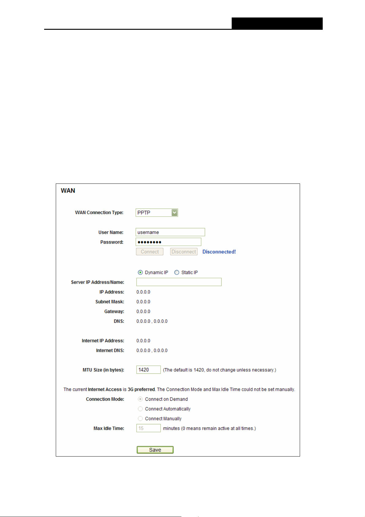
PW-3G401M 3G Wireless N Nano Router
¾ Connect Manually - You can configure the Router to make it connect or disconnect
manually. After a specified period of inactivity (Max Idle Time), the Router will disconnect
from your Internet connection, and you will not be able to re-establish your connection
automatically as soon as you attempt to access the Internet again. To use this option, click
the radio button. If you want your Internet connection to remain active at all times, enter "0"
in the Max Idle Time field. Otherwise, enter the number in minutes that you wish to have
the Internet connecting last unless a new link is requested.
Caution: Sometimes the connection cannot be disconnected although you specify a time to
Max Idle Time, since some applications are visiting the Internet continually in the
background.
6. If your ISP provides PPTP connection, please select PPTP/Russia PPTP option. And you
should enter the following parameters (Figure 4-17):
Figure 4-17 PPTP Settings
-49-
Page 58

PW-3G401M 3G Wireless N Nano Router
¾ User Name/Password - Enter the User Name and Password provided by your ISP. These
fields are case-sensitive.
¾ Dynamic IP/ Static IP - Choose either as you are given by your ISP and enter the ISP’s IP
address or the domain name.
If you choose static IP and enter the domain name, you should also enter the DNS
assigned by your ISP. And click the Save button.
Click the Connect button to connect immediately. Click the Disconnect button to
disconnect immediately.
¾ Connect on Demand - You can configure the Router to disconnect from your Internet
connection after a specified period of inactivity (Max Idle Time). If your Internet connection
has been terminated due to inactivity, Connect on Demand enables the Router to
automatically re-establish your connection as soon as you attempt to access the Internet
again. If you wish to activate Connect on Demand, click the radio button. If you want your
Internet connection to remain active at all times, enter 0 in the Max Idle Time field.
Otherwise, enter the number of minutes you want to have elapsed before your Internet
connection terminates.
¾ Connect Automatically - Connect automatically after the Router is disconnected. To use
this option, click the radio button.
¾ Connect Manually - You can configure the Router to make it connect or disconnect
manually. After a specified period of inactivity (Max Idle Time), the Router will disconnect
from your Internet connection, and you will not be able to re-establish your connection
automatically as soon as you attempt to access the Internet again. To use this option, click
the radio button. If you want your Internet connection to remain active at all times, enter "0"
in the Max Idle Time field. Otherwise, enter the number in minutes that you wish to have
the Internet connecting last unless a new link is requested.
Caution: Sometimes the connection cannot be disconnected although you specify a time to
Max Idle Time, since some applications are visiting the Internet continually in the
background.
Note:
)
If you don't know how to choose the appropriate connection type, click the Detect button to
allow the Router to automatically search your Internet connection for servers and protocols. The
connection type will be reported when an active Internet service is successfully detected by the
Router. This report is for your reference only. To make sure the connection type your ISP
provides, please refer to the ISP. The various types of Internet connections that the Router can
detect are as follows:
-50-
Page 59

PW-3G401M 3G Wireless N Nano Router
z PPPoE - Connections which use PPPoE that requires a user name and password.
z Dynamic IP - Connections which use dynamic IP address assignment.
z Static IP - Connections which use static IP address assignment.
The Router can not detect PPTP/L2TP/BigPond connections with your ISP. If your ISP uses
one of these protocols, then you must configure your connection manually.
4.6.4 MAC Clone
Choose menu “Network→MAC Clone”, you can configure the MAC address of the WAN on
the screen below, Figure 4-18:
Figure 4-18 MAC Address Clone
Some ISPs require that you register the MAC Address of your adapter. Changes are rarely
needed here.
¾ WAN MAC Address - This field displays the current MAC address of the WAN port. If
your ISP requires you to register the MAC address, please enter the correct MAC address
into this field in XX-XX-XX-XX-XX-XX format(X is any hexadecimal digit).
¾ Your PC's MAC Address - This field displays the MAC address of the PC that is
managing the Router. If the MAC address is required, you can click the Clone MAC
Address To button and this MAC address will fill in the WAN MAC Address field.
Click Restore Factory MAC to restore the MAC address of WAN port to the factory default
value.
Click the Save button to save your settings.
Note:
)
Only the PC on your LAN can use the MAC Address Clone function.
4.6.5 LAN
Choose menu “Network→LAN”, you can configure the IP parameters of the LAN on the screen
as below.
-51-
Page 60
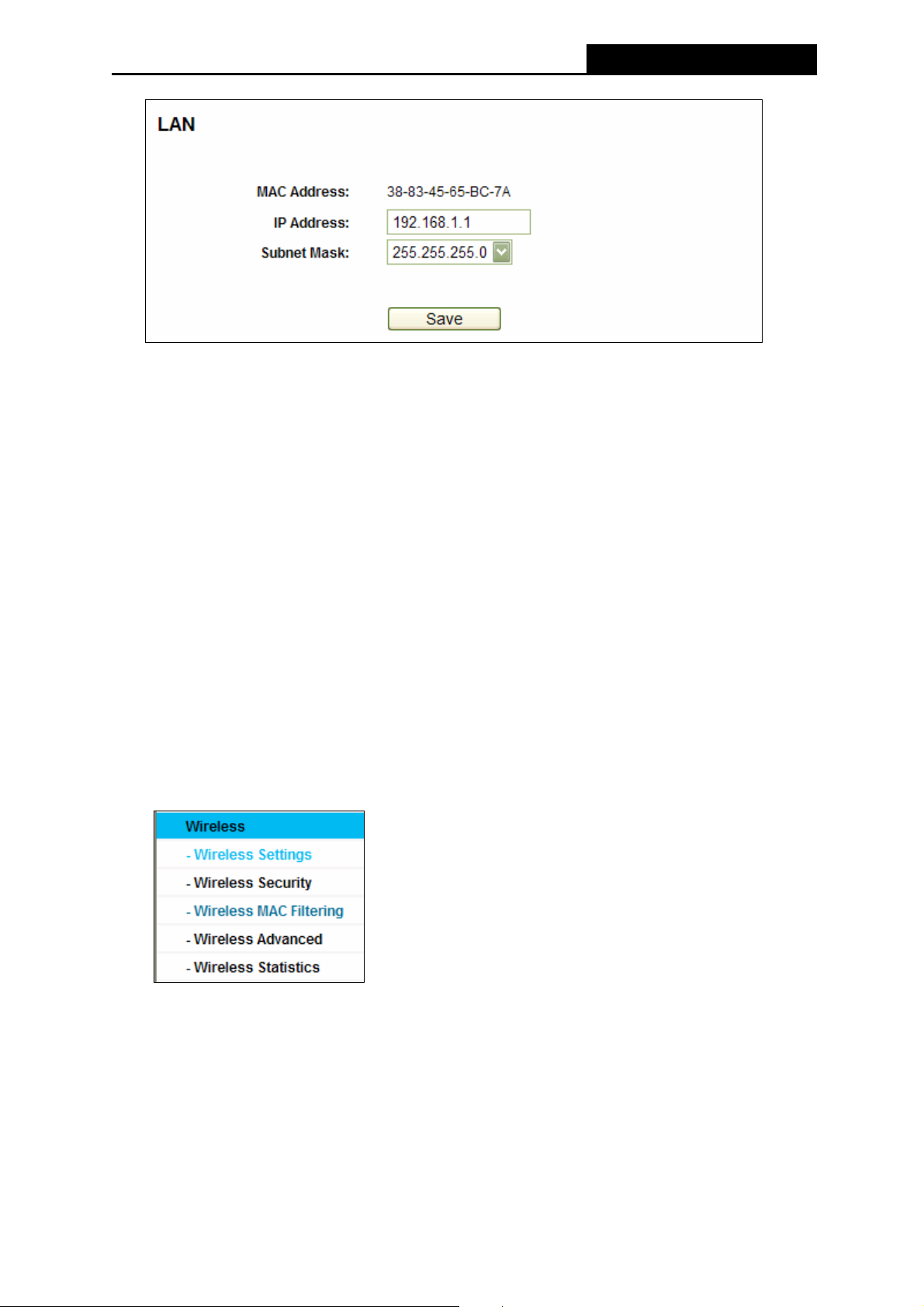
PW-3G401M 3G Wireless N Nano Router
Figure 4-19 LAN
¾ MAC Address - The physical address of the Router, as seen from the LAN. The value
can't be changed.
¾ IP Address - Enter the IP address of your Router or reset it in dotted-decimal notation
(factory default: 192.168.1.1).
¾ Subnet Mask - An address code that determines the size of the network. Normally use
255.255.255.0 as the subnet mask.
Note:
)
1) If you change the IP Address of LAN, you must use the new IP Address to login the Router.
2) If the new LAN IP Address you set is not in the same subnet, the IP Address pool of the
DHCP server will change accordingly at the same time,while the Virtual Server and DMZ
Host will not take effect until they are re-configured.
4.7 Wireless
Figure 4-20 Wireless menu
There are five submenus under the Wireless menu (shown in
Wireless Security, Wireless MAC Filtering, Wireless Advanced and Wireless Statistics.
Click any of them, and you will be able to configure the corresponding function.
Figure 4-20): Wireless Settings,
4.7.1 Wireless Settings
Choose menu “Wireless→Wireless Settings”, you can configure the basic settings for the
wireless network on this page.
-52-
Page 61
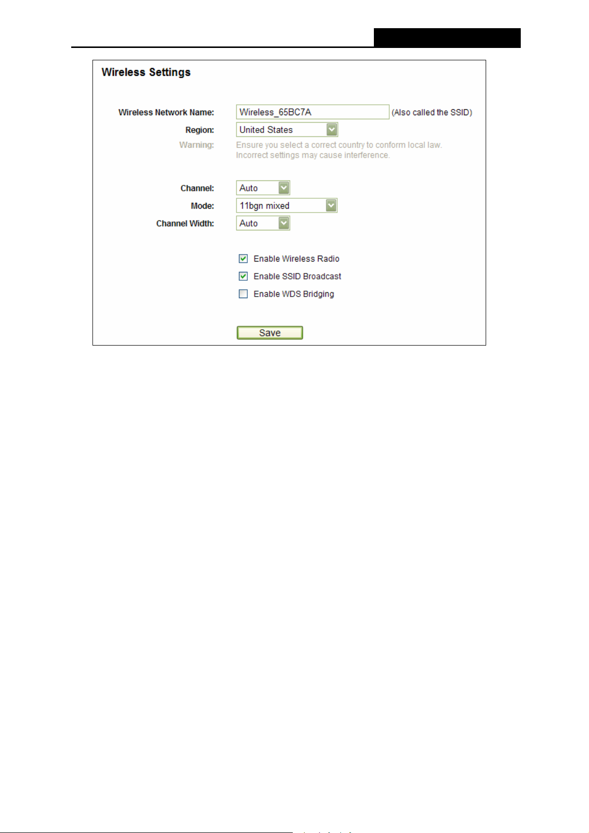
PW-3G401M 3G Wireless N Nano Router
Figure 4-21 Wireless Settings
¾ Wireless Network Name - Enter a value of up to 32 characters. The same name of
Wireless Network Name must be assigned to all wireless devices in your network.
Considering your wireless network security, the default Wireless Network Name is set to
be Wireless_XXXXXX (XXXXXX indicates the last six unique numbers of each Router’s
MAC address). This value is case-sensitive. For example, TEST is NOT the same as test.
¾ Region - Select your region from the pull-down list. This field specifies the region where
the wireless function of the Router can be used. It may be illegal to use the wireless
function of the Router in a region other than one of those specified in this field. If your
country or region is not listed, please contact your local government agency for
assistance.
Note:
)
Limited by local law regulations, version for North America does not have region selection option.
¾ Channel - This field determines which operating frequency will be used. The default
channel is set to Auto, so the Router will choose the best channel automatically. It is not
necessary to change the wireless channel unless you notice interference problems with
another nearby access point.
¾ Mode - Select the desired mode. The default setting is 11bgn mixed.
11b only - Select if all of your wireless clients are 802.11b.
11g only - Select if all of your wireless clients are 802.11g.
11n only - Select if all of your wireless clients are 802.11n.
11bg mixed - Select if you are using both 802.11b and 802.11g wireless clients.
-53-
Page 62
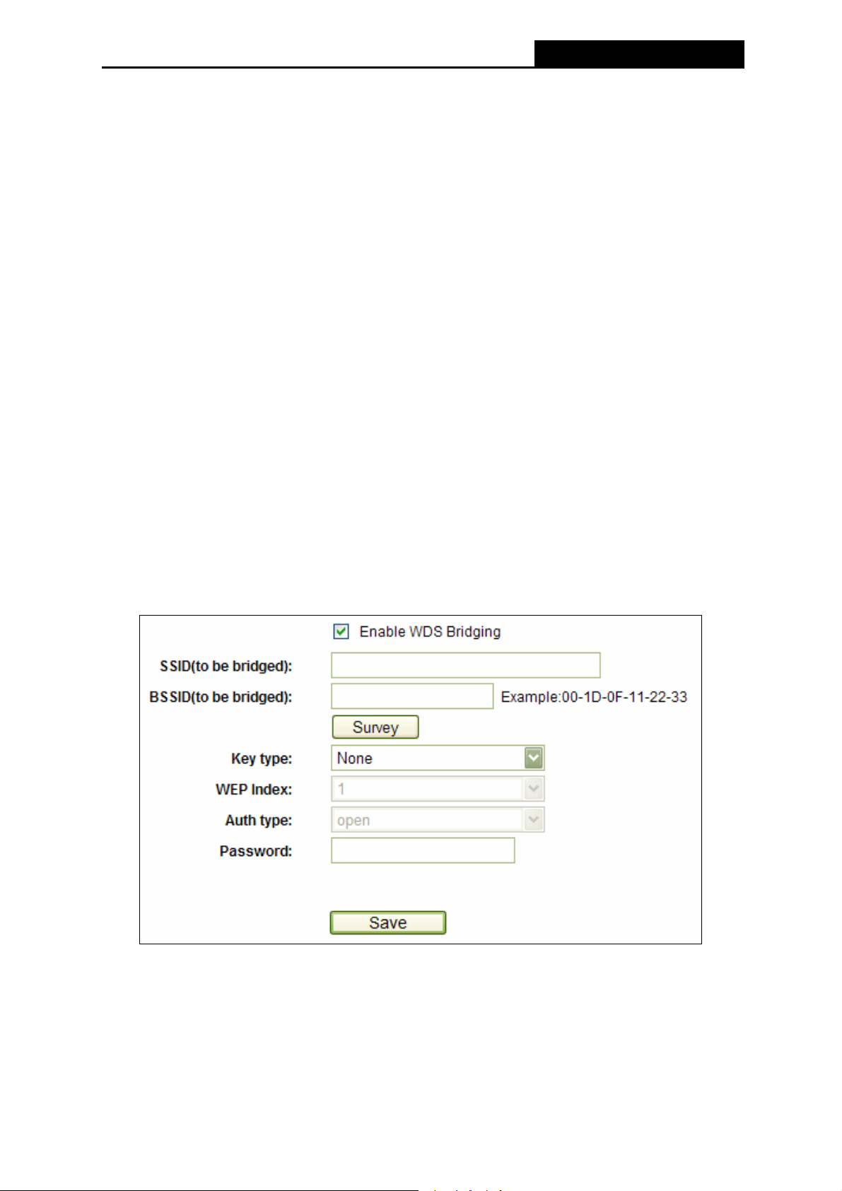
PW-3G401M 3G Wireless N Nano Router
11bgn mixed - Select if you are using a mix of 802.11b, 11g, and 11n wireless clients.
Select the desired wireless mode. When 802.11g mode is selected, only 802.11g wireless
stations can connect to the Router. When 802.11n mode is selected, only 802.11n
wireless stations can connect to the AP. It is strongly recommended that you set the Mode
to 802.11b&g&n, and all of 802.11b, 802.11g, and 802.11n wireless stations can connect
to the Router.
¾ Channel width - Select any channel width from the pull-down list. The default setting is
automatic, which can adjust the channel width for your clients automatically.
Note:
)
If 11b only, 11g only, or 11bg mixed is selected in the Mode field, the Channel Width
selecting field will turn grey and the value will become 20M, which is unable to be changed.
¾ Max Tx Rate - You can limit the maximum tx rate of the Router through this field.
¾ Enable Wireless Router Radio - The wireless radio of this Router can be enabled or
disabled to allow wireless stations access.
¾ Enable SSID Broadcast - When wireless clients survey the local area for wireless networks
to associate with, they will detect the SSID broadcast by the Router. If you select the Enable
SSID Broadcast checkbox, the Wireless Router will broadcast its name (SSID) on the air.
¾ Enable WDS Bridging - Check this box to enable WDS Bridging. With this function, the
Router can bridge two or more WLANs. If this checkbox is selected, you will have to set the
following parameters as shown below. Make sure the following settings are correct
¾ SSID(to be bridged) - The SSID of the AP your Router is going to connect to as a
client. You can also use the search function to select the SSID to join.
¾ BSSID(to be bridged) - The BSSID of the AP your Router is going to connect to as a
client. You can also use the search function to select the BSSID to join.
¾ Survey - Click this button, you can search the AP which runs in the current channel.
-54-
Page 63
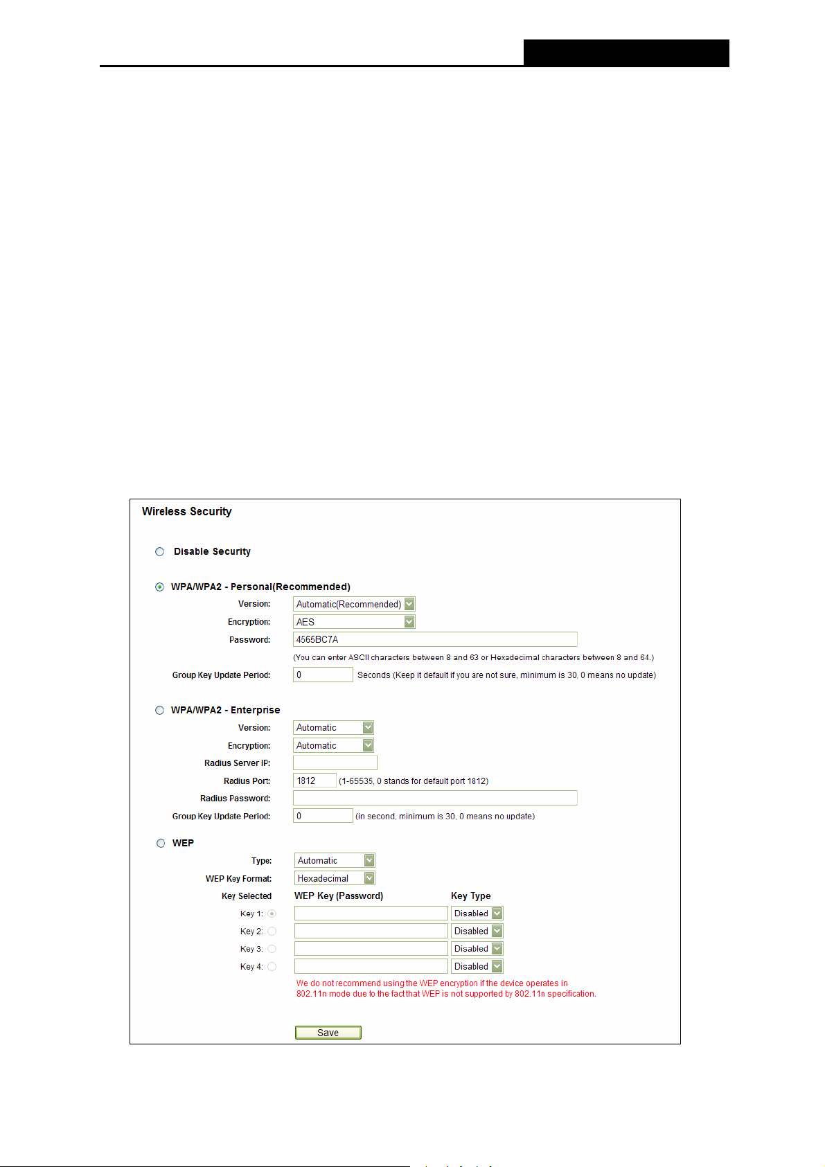
PW-3G401M 3G Wireless N Nano Router
¾ Key type - This option should be chosen according to the AP's security configuration.
It is recommended that the security type is the same as your AP's security type.
¾ WEP Index - This option should be chosen if the key type is WEP(ASCII) or
WEP(HEX).It indicates the index of the WEP key.
¾ Auth Type - This option should be chosen if the key type is WEP(ASCII) or
WEP(HEX).It indicates the authorization type of the Root AP.
¾ Password - If the AP your Router is going to connect needs password, you need to fill
the password in this blank.
4.7.2 Wireless Security
Choose menu “Wireless→Wireless Security”, you can configure the security settings of your
wireless network.
There are five wireless security modes supported by the Router: WEP (Wired Equivalent
Privacy), WPA (Wi-Fi Protected Access), WPA2 (Wi-Fi Protected Access 2), WPA2-PSK
(Pre-Shared Key), WPA-PSK (Pre-Shared Key).
Figure 4-22
-55-
Page 64

PW-3G401M 3G Wireless N Nano Router
¾ Disable Security - If you do not want to use wireless security, select this check box, but it’s
strongly recommended to choose one of the following modes to enable security.
¾ WPA/WPA2 – Personal (Recommended) - It’s the WPA/WPA2 authentication type
based on pre-shared passphrase.
• Version - you can choose the version of the WPA-PSK security on the drop-down list.
The default setting is Automatic, which can select
or WPA2-PSK (Pre-shared key of WPA) automatically based on the wireless station's
capability and request.
• Encryption - When WPA-PSK or WPA is set as the Authentication Type, you can select
either Automatic, or TKIP or AES as Encryption.
Note:
)
If you check the WPA/WPA2 – Personal (Recommended) radio button and choose TKIP
encryption, you will find a notice in red as shown in Figure 4-23.
WPA-PSK (Pre-shared key of WPA)
Figure 4-23
• PSK Password - You can enter ASCII characters between 8 and 63 characters or 8 to
64 Hexadecimal characters.
• Group Key Update Period - Specify the group key update interval in seconds. The
value should be 30 or above. Enter 0 to disable the update.
Be sure to click the Save button to save your settings on this page.
¾ WPA /WPA2 - Enterprise - It’s based on Radius Server.
• Version - you can choose the version of the WPA security on the pull-down list. The
default setting is Automatic, which can select
(WPA version 2) automatically based on the wireless station's capability and request.
• Encryption - You can select either Automatic, or TKIP or AES.
Note:
)
If you check the WPA/WPA2 - Enterprise radio button and choose TKIP encryption, you
will find a notice in red as shown in Figure 4-24.
WPA (Wi-Fi Protected Access) or WPA2
-56-
Page 65

PW-3G401M 3G Wireless N Nano Router
Figure 4-24
• Radius Server IP - Enter the IP address of the Radius Server.
• Radius Port - Enter the port that radius service used.
• Radius Password - Enter the password for the Radius Server.
• Group Key Update Period - Specify the group key update interval in seconds. The
value should be 30 or above. Enter 0 to disable the update.
¾ WEP - It is based on the IEEE 802.11 standard. If you select this check box, you will find a
notice in red as show in Figure 4-25.
Figure 4-25
• Type - you can choose the type for the WEP security on the pull-down list. The default
setting is Automatic, which can select
Open System or Shared Key authentication type
automatically based on the wireless station's capability and request.
• WEP Key Format - Hexadecimal and ASCII formats are provided. Hexadecimal
format stands for any combination of hexadecimal digits (0-9, a-f, A-F) in the specified
length. ASCII format stands for any combination of keyboard characters in the specified
length.
• WEP Key- Select which of the four keys will be used and enter the matching WEP key
that you create. Make sure these values are identical on all wireless stations in your
network.
-57-
Page 66

PW-3G401M 3G Wireless N Nano Router
• Key Type - You can select the WEP key length (64-bit, or 128-bit, or 152-bit.) for
encryption. "Disabled" means this WEP key entry is invalid.
64-bit -
not promoted) or 5 ASCII characters.
128-bit - You can enter 26 hexadecimal digits (any combination of 0-9, a-f, A-F, zero key
is not promoted) or 13 ASCII characters.
152-bit - You can enter 32 hexadecimal digits (any combination of 0-9, a-f, A-F, zero key
is not promoted) or 16 ASCII characters.
)
If you do not set the key, the wireless security function is still disabled even if you have
selected Shared Key as Authentication Type.
You can enter 10 hexadecimal digits (any combination of 0-9, a-f, A-F, zero key is
Note:
4.7.3 Wireless MAC Filtering
Choose menu “Wireless → Wireless MAC Filtering”, you can control the wireless access by
configuring the Wireless MAC Address Filtering function, shown in Figure 4-26.
Figure 4-26 Wireless MAC address Filtering
To filter wireless users by MAC Address, click Enable. The default setting is Disabled.
¾ MAC Address - The wireless station's MAC address that you want to filter.
¾ Status - The status of this entry either Enabled or Disabled.
¾ Description - A simple description of the wireless station.
To Add a Wireless MAC Address filtering entry, click the Add New… button. The "Add or
Modify Wireless MAC Address Filtering entry" page will appear, shown in Figure 4-27:
-58-
Page 67

PW-3G401M 3G Wireless N Nano Router
Figure 4-27 Add or Modify Wireless MAC Address Filtering entry
To add a MAC Address Filtering entry, follow these instructions:
1. Enter the appropriate MAC Address into the MAC Address field. The format of the MAC
Address is XX-XX-XX-XX-XX-XX (X is any hexadecimal digit). For example:
00-0A-EB-00-07-8A.
2. Enter a simple description of the wireless station in the Description field. For example:
Wireless station A.
3. Status - Select Enabled or Disabled for this entry on the Status pull-down list.
4. Click the Save button to save this entry.
To modify or delete an existing entry:
1. Click the Modify in the entry you want to modify. If you want to delete the entry, click the
Delete.
2. Modify the information.
3. Click the Save button.
Click the Enable All button to make all entries enabled
Click the Disable All button to make all entries disabled.
Click the Delete All button to delete all entries
Click the Next button to go to the next page
Click the Previous button to return to the previous page.
For example: If you desire that the wireless station A with MAC address 00-0A-EB-00-07-8A
and the wireless station B with MAC address 00-0A-EB-00-23-11 are able to access the Router,
but all the other wireless stations cannot access the Router, you can configure the Wireless
MAC Filtering list by following these steps:
1. Click the Enable button to enable this function.
-59-
Page 68
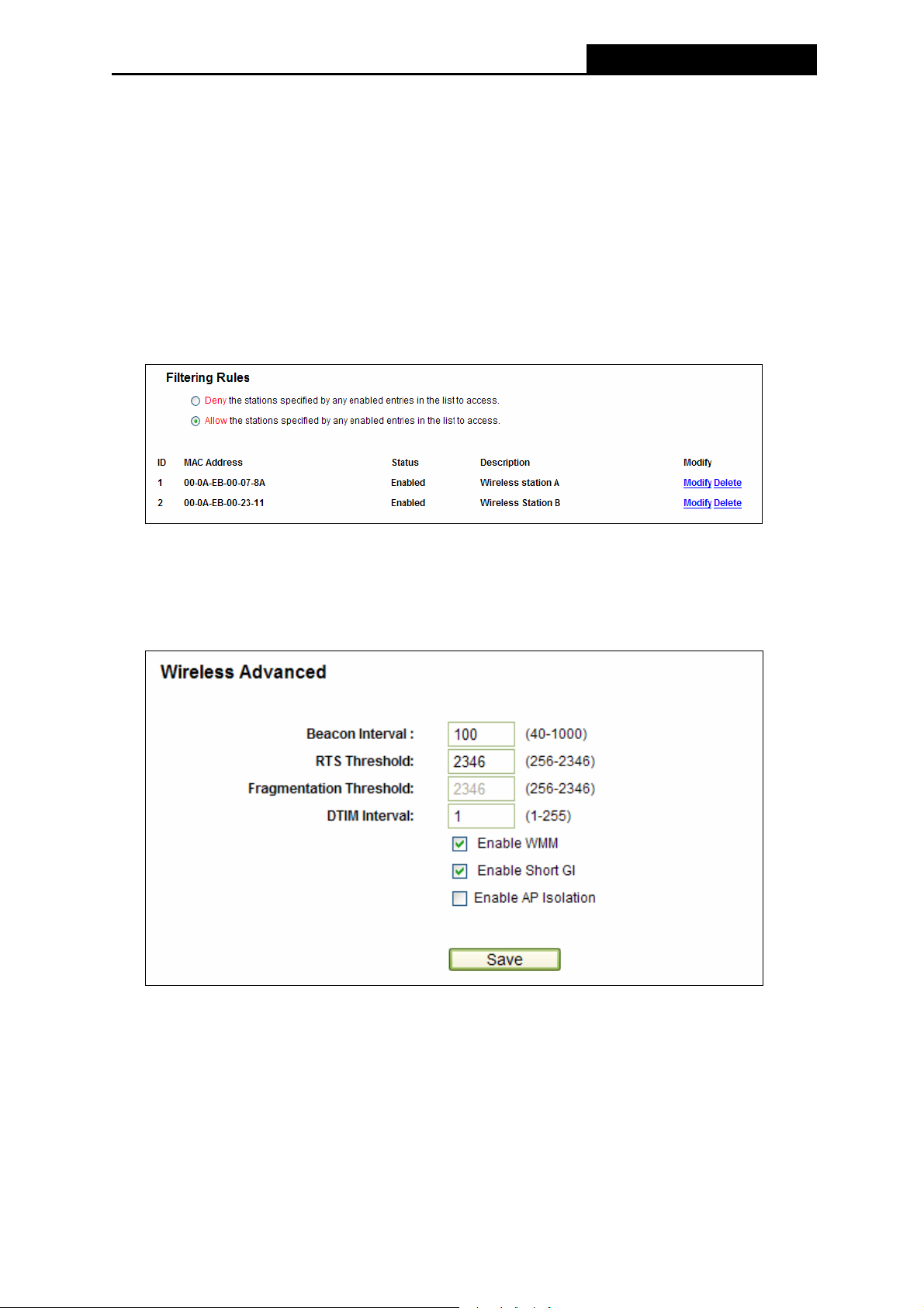
PW-3G401M 3G Wireless N Nano Router
2. Select the radio button: Allow the stations specified by any enabled entries in the list to
access for Filtering Rules.
3. Delete all or disable all entries if there are any entries already.
4. Click the Add New... button and enter the MAC address 00-0A-EB-00-07-8A
/00-0A-EB-00-23-11 in the MAC Address field, then enter wireless station A/B in the
Description field, while select Enabled in the Status pull-down list. Finally, click the Save
and the Back button.
The filtering rules that configured should be similar to the following list:
4.7.4 Wireless Advanced
Choose menu “Wireless→Wireless Advanced”, you can configure the advanced settings of
your wireless network.
Figure 4-28 Wireless Advanced
¾ Beacon Interval - Enter a value between 40-1000 milliseconds for Beacon Interval here.
The beacons are the packets sent by the Router to synchronize a wireless network.
Beacon Interval value determines the time interval of the beacons. The default value is
100.
¾ RTS Threshold - Here you can specify the RTS (Request to Send) Threshold. If the
packet is larger than the specified RTS Threshold size, the Router will send RTS frames to
-60-
Page 69

PW-3G401M 3G Wireless N Nano Router
a particular receiving station and negotiate the sending of a data frame. The default value
is 2346.
¾ Fragmentation Threshold - This value is the maximum size determining whether packets
will be fragmented. Setting the Fragmentation Threshold too low may result in poor
network performance since excessive packets. 2346 is the default setting and is
recommended.
¾ DTIM Interval - This value determines the interval of the Delivery Traffic Indication
Message (DTIM). A DTIM field is a countdown field informing clients of the next window for
listening to broadcast and multicast messages. When the Router has buffered broadcast
or multicast messages for associated clients, it sends the next DTIM with a DTIM Interval
value. You can specify the value between 1-255 Beacon Intervals. The default value is 1,
which indicates the DTIM Interval is the same as Beacon Interval.
¾ Enable WMM - WMM function can guarantee the packets with high- priority messages
being transmitted preferentially. It is strongly recommended enabled.
¾ Enable Short GI - This function is recommended for it will increase the data capacity by
reducing the guard interval time
¾ Enabled AP Isolation - This function can isolate wireless stations on your network from
.
each other. Wireless devices will be able to communicate with the Router but not with each
other. To use this function, check this box. AP Isolation is disabled by default.
Note:
)
If you are not familiar with the setting items on this page, it's strongly recommended to keep the
provided default values; otherwise it may result in lower wireless network performance.
4.7.5 Wireless Statistics
Choose menu “Wireless→Wireless Statistics”, you can see the MAC Address, Current Status,
Received Packets and Sent Packets for each connected wireless station.
Figure 4-29 The Router attached wireless stations
¾ MAC Address - The connected wireless station's MAC address
¾ Current Status - The connected wireless station's running status, one of STA-AUTH /
-61-
Page 70

PW-3G401M 3G Wireless N Nano Router
STA-ASSOC / STA-JOINED / WPA / WPA-PSK / WPA2 / WPA2-PSK / AP-UP /
AP-DOWN / Disconnected
¾ Received Packets - Packets received by the station
¾ Sent Packets - Packets sent by the station
You cannot change any of the values on this page. To update this page and to show the
current connected wireless stations, click on the Refresh button.
If the numbers of connected wireless stations go beyond one page, click the Next button to go
to the next page and click the Previous button to return the previous page.
Note:
)
This page will be refreshed automatically every 5 seconds.
4.8 DHCP
Figure 4-30 The DHCP menu
There are three submenus under the DHCP menu (shown in
DHCP Clients List and Address Reservation. Click any of them, and you will be able to
configure the corresponding function.
Figure 4-30): DHCP Settings,
4.8.1 DHCP Settings
Choose menu “DHCP→DHCP Settings”, you can configure the DHCP Server on the page
(shown in
Protocol) server, which provides the TCP/IP configuration for all the PC(s) that are connected to
the Router on the LAN.
Figure 4-31).The Router is set up by default as a DHCP (Dynamic Host Configuration
-62-
Page 71

PW-3G401M 3G Wireless N Nano Router
Figure 4-31 DHCP Settings
¾ DHCP Server - Enable or Disable the DHCP server. If you disable the Server, you must
have another DHCP server within your network or else you must configure the computer
manually.
¾ Start IP Address - Specify an IP address for the DHCP Server to start with when
assigning IP addresses. 192.168.1.100 is the default start address.
¾ End IP Address - Specify an IP address for the DHCP Server to end with when assigning
IP addresses. 192.168.1.199 is the default end address.
¾ Address Lease Time - The Address Lease Time is the amount of time a network user
will be allowed connection to the Router with their current dynamic IP Address. Enter the
amount of time in minutes and the user will be "leased" this dynamic IP Address. After the
time is up, the user will be automatically assigned a new dynamic IP address. The range
of the time is 1 ~ 2880 minutes. The default value is 120 minutes.
¾ Default Gateway - (Optional) Suggest to input the IP address of the LAN port of the
Router, default value is 192.168.1.1.
¾ Default Domain - (Optional) Input the domain name of your network.
¾ Primary DNS - (Optional) Input the DNS IP address provided by your ISP. Or consult your
ISP.
¾ Secondary DNS - (Optional) Input the IP address of another DNS server if your ISP
provides two DNS servers.
Note:
)
To use the DHCP server function of the Router, you must configure all computers on the LAN as
"Obtain an IP address automatically" mode.
-63-
Page 72

PW-3G401M 3G Wireless N Nano Router
4.8.2 DHCP Clients List
Choose menu “DHCP→DHCP Clients List”, you can view the information about the clients
attached to the Router in the next screen (shown in Figure 4-32
).
Figure 4-32 DHCP Clients List
¾ ID - The index of the DHCP Client
¾ Client Name - The name of the DHCP client
¾ MAC Address - The MAC address of the DHCP client
¾ Assigned IP - The IP address that the Router has allocated to the DHCP client.
¾ Lease Time - The time of the DHCP client leased. After the dynamic IP address has
expired, a new dynamic IP address will be automatically assigned to the user.
You cannot change any of the values on this page. To update this page and to show the
current attached devices, click the Refresh button.
4.8.3 Address Reservation
Choose menu “DHCP→Address Reservation”, you can view and add a reserved addresses
for clients via the next screen (shown in Figure 4-33).When you specify a reserved IP address
for a PC on the LAN, that PC will always receive the same IP address each time when it
accesses the DHCP server. Reserved IP addresses should be assigned to the servers that
require permanent IP settings.
Figure 4-33 Address Reservation
¾ MAC Address - The MAC address of the PC for which you want to reserve IP address.
¾ Assigned IP Address - The IP address of the Router reserved.
¾ Status - The status of this entry either Enabled or Disabled.
-64-
Page 73

PW-3G401M 3G Wireless N Nano Router
To Reserve IP addresses:
1. Click the Add New … button. (Pop-up Figure 4-34)
2. Enter the MAC address (in XX-XX-XX-XX-XX-XX format.) and IP address in
dotted-decimal notation of the computer you wish to add.
3. Click the Save button when finished.
Figure 4-34 Add or Modify an Address Reservation Entry
To modify or delete an existing entry:
1. Click the Modify in the entry you want to modify. If you want to delete the entry, click the
Delete.
2. Modify the information.
3. Click the Save button.
Click the Enable/ Disabled All button to make all entries enabled/disabled
Click the Delete All button to delete all entries
Click the Next button to go to the next page and click the Previous button to return the
previous page.
4.9 Forwarding
Figure 4-35 The Forwarding menu
There are four submenus under the Forwarding menu (shown in Figure 4-35): Virtual Servers,
Port Triggering, DMZ and UPnP. Click any of them, and you will be able to configure the
corresponding function.
-65-
Page 74

PW-3G401M 3G Wireless N Nano Router
4.9.1 Virtual Servers
Choose menu “Forwarding→Virtual Servers”, you can view and add virtual servers in the
next screen (shown in Figure 4-36). Virtual servers can be used for setting up public services
on your LAN, such as DNS, Email and FTP. A virtual server is defined as a service port, and all
requests from the Internet to this service port will be redirected to the computer specified by
the server IP. Any PC that was used for a virtual server must have a static or reserved IP
Address because its IP Address may be changed when using the DHCP function.
Figure 4-36 Virtual Servers
¾ Service Port - The numbers of External Ports. You can type a service port or a range of
service ports (in XXX – YYY format, XXX is the start port number, YYY is the end port
number).
¾ Internal Port - The Internal Service Port number of the PC running the service application.
You can leave it blank if the Internal Port is the same as the Service Port, or enter a
specific port number when Service Port is a single one.
¾ IP Address - The IP Address of the PC providing the service application.
¾ Protocol - The protocol used for this application, either TCP, UDP, or All (all protocols
supported by the Router).
¾ Status - The status of this entry either Enabled or Disabled.
To setup a virtual server entry:
1. Click the Add New… button. (pop-up Figure 4-37)
2. Select the service you want to use from the Common Service Port list. If the Common
Service Port list does not have the service that you want to use, type the number of the
service port or service port range in the Service Port box.
3. Type the IP Address of the computer in the IP Address box.
4. Select the protocol used for this application, either TCP or UDP, or All.
5. Select the Enable check box to enable the virtual server.
6. Click the Save button.
-66-
Page 75
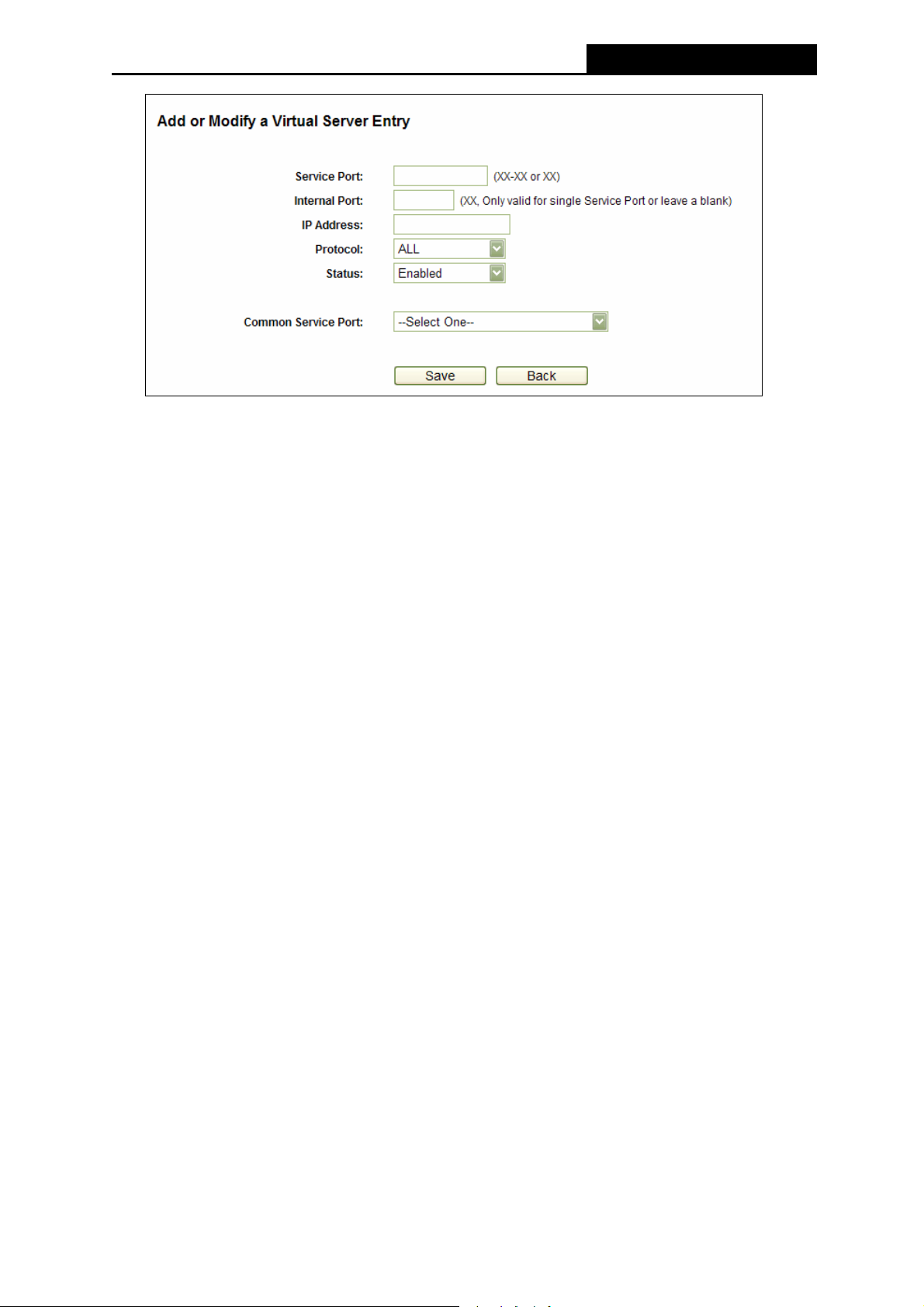
PW-3G401M 3G Wireless N Nano Router
Figure 4-37 Add or Modify a Virtual Server Entry
Note:
)
If your computer or server has more than one type of available service, please select another
service, and enter the same IP Address for that computer or server.
To modify or delete an existing entry:
1. Click the Modify in the entry you want to modify. If you want to delete the entry, click the
Delete.
2. Modify the information.
3. Click the Save button.
Click the Enable/ Disable All button to make all entries enabled/ disabled.
Click the Delete All button to delete all entries.
Click the Next button to go to the next page and click the Previous button to return the previous
page.
Note:
)
If you set the service port of the virtual server as 80, you must set the Web management port on
Security –> Remote Management page to be any other value except 80 such as 8080.
Otherwise there will be a conflict to disable the virtual server.
4.9.2 Port Triggering
Choose menu “Forwarding→Port Triggering”, you can view and add port triggering in the next
screen (shown in Figure 4-38). Some applications require multiple connections, like Internet
ames, video conferencing, Internet calling and so on. These applications cannot work with a
pure NAT Router. Port Triggering is used for some of these applications that can work with an
NAT Router.
-67-
Page 76

PW-3G401M 3G Wireless N Nano Router
Figure 4-38 Port Triggering
Once the Router is configured, the operation is as follows:
1. A local host makes an outgoing connection using a destination port number defined in the
Trigger Port field.
2. The Router records this connection, opens the incoming port or ports associated with this
entry in the Port Triggering table, and associates them with the local host.
3. When necessary the external host will be able to connect to the local host using one of the
ports defined in the Incoming Ports field.
¾ Trigger Port - The port for outgoing traffic. An outgoing connection using this port will
"Trigger" this rule.
¾ Trigger Protocol - The protocol used for Trigger Ports, either TCP, UDP, or All (all
protocols supported by the Router).
¾ Incoming Port - The port or port range used by the remote system when it responds to the
outgoing request. A response using one of these ports will be forwarded to the PC that
triggered this rule. You can input at most 5 groups of ports (or port section). Every group of
ports must be set apart with ",". For example, 2000-2038, 2050-2051, 2085, 3010-3030.
¾ Incoming Protocol - The protocol used for Incoming Ports Range, either TCP or UDP, or
ALL (all protocols supported by the Router).
¾ Status - The status of this entry either Enabled or Disabled.
To add a new rule, follow the steps below.
1. Click the Add New… button, the next screen will pop-up as shown in Figure 4-39.
2. Select a common application from the Common Applications drop-down list, then the
Trigger Port field and the Incoming Ports field will be automatically filled. If the Common
Applications do not have the application you need, enter the Trigger Port and the
Incoming Ports manually.
3. Select the protocol used for Trigger Port from the Trigger Protocol drop-down list, either
TCP, UDP, or All.
4. Select the protocol used for Incoming Ports from the Incoming Protocol drop-down list,
either TCP or UDP, or All.
5. Select Enable in Status field.
6. Click the Save button to save the new rule.
-68-
Page 77
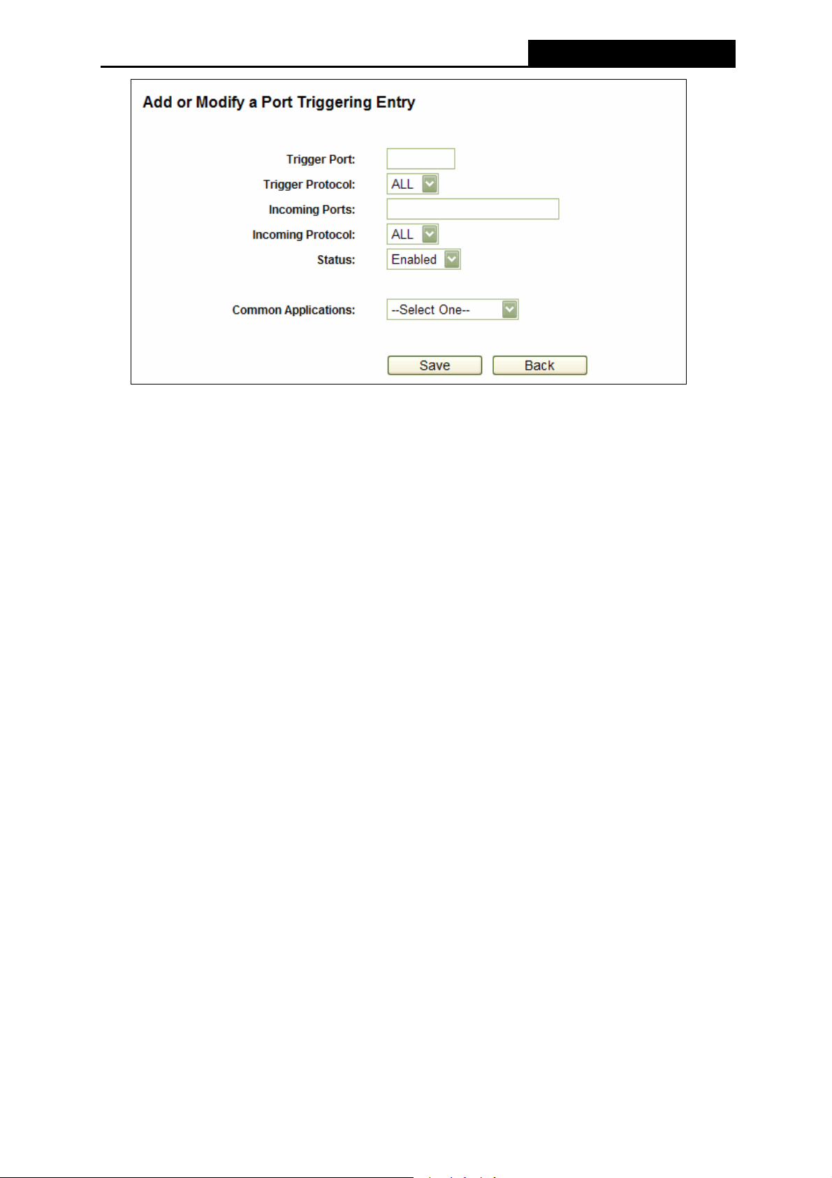
PW-3G401M 3G Wireless N Nano Router
Figure 4-39 Add or Modify a Triggering Entry
To modify or delete an existing entry:
1. Click the Modify in the entry you want to modify. If you want to delete the entry, click the
Delete.
2. Modify the information.
3. Click the Save button.
Click the Enable All button to make all entries enabled
Click the Disable All button to make all entries disabled.
Click the Delete All button to delete all entries
Note:
)
1) When the trigger connection is released, the according opening ports will be closed.
2) Each rule allowed to be used only by one host on LAN synchronously. The trigger
connection of other hosts on LAN will be refused.
3) Incoming Port Range cannot overlap each other.
4.9.3 DMZ
Choose menu “Forwarding→DMZ”, you can view and configure DMZ host in the screen
(shown in Figure 4-40).The DMZ host feature allows one local host to be exposed to the
Internet for a special-purpose service such as Internet gaming or videoconferencing. DMZ host
forwards all the ports at the same time. Any PC whose port is being forwarded must have its
DHCP client function disabled and should have a new static IP Address assigned to it because
its IP Address may be changed when using the DHCP function.
-69-
Page 78
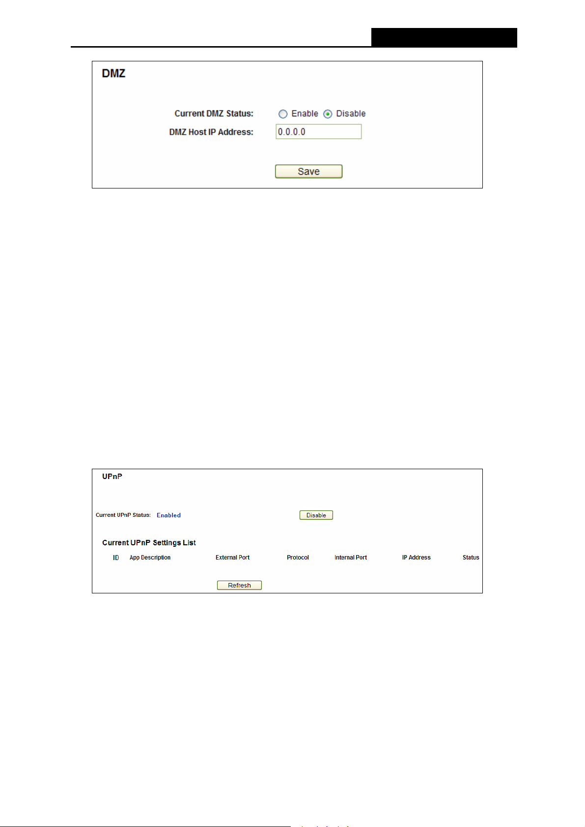
PW-3G401M 3G Wireless N Nano Router
Figure 4-40 DMZ
To assign a computer or server to be a DMZ server:
1. Click the Enable radio button
2. Enter the local host IP Address in the DMZ Host IP Address field
3. Click the Save button.
Note:
)
After you set the DMZ host, the firewall related to the host will not work.
4.9.4 UPnP
Choose menu “Forwarding→UPnP”, you can view the information about UPnP(Universal Plug
and Play) in the screen (shown in Figure 4-41).The UPnP feature allows the devices, such as
Internet computers, to access the local host resources or devices as needed. UPnP devices
can be automatically discovered by the UPnP service application on the LAN.
Figure 4-41 UPnP Setting
¾ Current UPnP Status - UPnP can be enabled or disabled by clicking the Enable or
Disable button. As allowing this may present a risk to security, this feature is enabled by
default.
¾ Current UPnP Settings List - This table displays the current UPnP information.
z App Description -The description provided by the application in the UPnP request
z External Port - External port, which the Router opened for the application.
z Protocol - Shows which type of protocol is opened.
-70-
Page 79
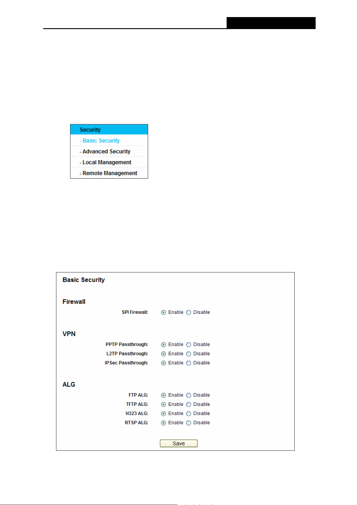
PW-3G401M 3G Wireless N Nano Router
z Internal Port - Internal port, which the Router opened for local host.
z IP Address - The UPnP device that is currently accessing the Router.
z Status - The port’s status displayed here. “Enabled” means that port is still active.
Otherwise, the port is inactive.
Click Refresh to update the Current UPnP Settings List.
4.10 Security
Figure 4-42 The Security menu
There are four submenus under the Security menu as shown in Figure 4-42: Basic Security,
Advanced Security, Local Management and Remote Management. Click any of them, and
you will be able to configure the corresponding function.
4.10.1 Basic Security
Choose menu “Security → Basic Security”, you can configure the basic security in the
screen as shown in Figure 4-43.
Figure 4-43 Basic Security
-71-
Page 80

PW-3G401M 3G Wireless N Nano Router
¾ Firewall - A firewall protects your network from the outside world. Here you can enable or
disable the Router’s firewall.
z SPI Firewall - SPI (Stateful Packet Inspection, also known as dynamic packet filtering)
helps to prevent cyber attacks by tracking more state per session. It validates that the
traffic passing through the session conforms to the protocol. SPI Firewall is enabled by
factory default. If you want all the computers on the LAN exposed to the outside world,
you can disable it.
¾ VPN - VPN Passthrough must be enabled if you want to allow VPN tunnels using IPSec,
PPTP, or L2TP protocols to pass through the Router’s firewall.
z PPTP Passthrough - Point-to-Point Tunneling Protocol (PPTP) allows the
Point-to-Point Protocol (PPP) to be tunneled through an IP network. To allow PPTP
tunnels to pass through the Router, keep the default, Enable.
z L2TP Passthrough - Layer 2 Tunneling Protocol (L2TP) is the method used to enable
Point-to-Point sessions via the Internet on the Layer 2 level. To allow L2TP tunnels to
pass through the Router, keep the default, Enable.
z IPSec Passthrough - Internet Protocol Security (IPSec) is a suite of protocols for
ensuring private, secure communications over Internet Protocol (IP) networks, through
the use of cryptographic security services. To allow IPSec tunnels to pass through the
Router, keep the default, Enable.
¾ ALG - It is recommended to enable Application Layer Gateway (ALG) because ALG allows
customized Network Address Translation (NAT) traversal filters to be plugged into the
gateway to support address and port translation for certain application layer "control/data"
protocols such as FTP, TFTP, H323, RTSP etc.
z FTP ALG - Select Enable, to allow FTP servers to operate properly.
z TFTP ALG - Select Enable, to allow TFTP servers to operate properly.
z H323 ALG - Select Enable, to allow H323 services to operate properly.
z RTSP ALG - Select Enable, to allow RTSP services to operate properly.
Click the Save button to save your settings.
4.10.2 Advanced Security
Choose menu “Security → Advanced Security”, you can protect the Router from being
attacked by TCP-SYN Flood, UDP Flood and ICMP-Flood in the screen as shown in Figure
4-44.
-72-
Page 81

PW-3G401M 3G Wireless N Nano Router
Figure 4-44 Advanced Security
¾ Packets Statistics Interval (5~60) - The default value is 10. Select a value between 5
and 60 seconds from the drop-down list. The Packets Statistics Interval value indicates
the time section of the packets statistics. The result of the statistics is used for analysis by
SYN Flood, UDP Flood and ICMP-Flood.
¾ DoS Protection - Denial of Service protection. Check the Enable or Disable button to
enable or disable the DoS protection function. Only when it is enabled, will the flood filters
be enabled.
¾ Enable ICMP-FLOOD Attack Filtering - Enable or Disable the ICMP-FLOOD Attack
Filtering.
¾ ICMP-FLOOD Packets Threshold (5~3600) - The default value is 50. Enter a value
between 5 ~ 3600. When the current ICMP-FLOOD Packets number is beyond the set
value, the Router will startup the blocking function immediately.
¾ Enable UDP-FLOOD Filtering - Enable or Disable the UDP-FLOOD Filtering.
¾ UDP-FLOOD Packets Threshold (5~3600) - The default value is 500. Enter a value
between 5 ~ 3600. When the current UPD-FLOOD Packets number is beyond the set value,
the Router will startup the blocking function immediately.
¾ Enable TCP-SYN-FLOOD Attack Filtering - Enable or Disable the TCP-SYN-FLOOD
Attack Filtering.
-73-
Page 82

PW-3G401M 3G Wireless N Nano Router
¾ TCP-SYN-FLOOD Packets Threshold (5~3600) - The default value is 50. Enter a value
between 5 ~ 3600. When the current TCP-SYN-FLOOD Packets numbers is beyond the
set value, the Router will startup the blocking function immediately.
¾ Ignore Ping Packet From WAN Port - Enable or Disable Ignore Ping Packet From WAN
Port. The default setting is disabled. If enabled, the ping packet from the Internet cannot
access the Router.
¾ Forbid Ping Packet From LAN Port - Enable or Disable Forbid Ping Packet From LAN
Port. The default setting is disabled. If enabled, the ping packet from LAN cannot access
the Router. This function can be used to defend against some viruses.
Click the Save button to save the settings.
Click the Blocked DoS Host List button to display the DoS host table by blocking.
4.10.3 Local Management
Choose menu “Security → Local Management”, you can configure the management rule in
the screen as shown in Figure 4-45. The management feature allows you to deny computers in
LAN from accessing the Router.
Figure 4-45 Local Management
By default, the radio button “All the PCs on the LAN are allowed to access the Router's
Web-Based Utility” is checked. If you want to allow PCs with specific MAC Addresses to
access the Setup page of the Router's Web-Based Utility locally from inside the network, check
the radio button “Only the PCs listed can browse the built-in web pages to perform
Administrator tasks”, and then enter each MAC Address in a separate field. The format for the
MAC Address is XX-XX-XX-XX-XX-XX (X is any hexadecimal digit). Only the PCs with MAC
address listed can use the password to browse the built-in web pages to perform Administrator
tasks while all the others will be blocked.
-74-
Page 83

PW-3G401M 3G Wireless N Nano Router
After click the Add button, your PC's MAC Address will be placed in the list above.
Click the Save button to save your settings.
Note:
)
If your PC is blocked but you want to access the Router again, use a pin to press and hold the
Reset button (hole) on the back panel for about 5 seconds to reset the Router’s factory
defaults on the Router’s Web-Based Utility.
4.10.4 Remote Management
Choose menu “Security → Remote Management”, you can configure the Remote
Management function in the screen as shown in Figure 4-46. This feature allows you to manage
your Router from a remote location via the Internet.
Figure 4-46 Remote Management
¾ Web Management Port - Web browser access normally uses the standard HTTP service
port 80. This Router's default remote management web port number is 80. For greater
security, you can change the remote management web port to a custom port by entering
that number in the box provided. Choose a number between 1 and 65534 but do not use
the number of any common service port.
¾ Remote Management IP Address - This is the current address you will use when
accessing your Router from the Internet. This function is disabled when the IP address is
set to the default value of 0.0.0.0. To enable this function change 0.0.0.0 to a valid IP
address. If set to 255.255.255.255, then all the hosts can access the Router from internet.
Note:
)
1) To access the Router, you should type your Router's WAN IP address into your browser's
address (in IE) or Location (in Navigator) box, followed by a colon and the custom port
number. For example, if your Router's WAN address is 202.96.12.8, and the port number
used is 8080, please enter http://202.96.12.8:8080 in your browser. Later, you may be
asked for the Router's password. After successfully entering the username and password,
you will be able to access the Router's web-based utility.
2) Be sure to change the Router's default password to a very secure password.
-75-
Page 84

PW-3G401M 3G Wireless N Nano Router
4.11 Parental Control
Choose menu “Parental Control”, and you can configure the parental control in the screen as
shown in Figure 4-47. The Parental Control function can be used to control the internet activities
of the child, limit the child to access certain websites and restrict the time of surfing.
Figure 4-47 Parental Control Settings
¾ Parental Control - Check Enable if you want this function to take effect, otherwise check
Disable.
¾ MAC Address of Parental PC - In this field, enter the MAC address of the controlling PC,
or you can make use of the Copy To Above button below.
¾ MAC Address of Your PC - This field displays the MAC address of the PC that is
managing this Router. If the MAC Address of your adapter is registered, you can click the
Copy To Above button to fill this address to the MAC Address of Parental PC field above.
¾ Website Description - Description of the allowed website for the PC controlled.
¾ Schedule - The time period allowed for the PC controlled to access the Internet. For
detailed information, please go to “Access Control → Schedule”.
¾ Modify - Here you can edit or delete an existing entry.
To add a new entry, please follow the steps below.
1. Click the Add New… button and the next screen will pop-up as shown in Figure 4-48.
2. Enter the MAC address of the PC (e.g. 00-11-22-33-44-AA) you’d like to control in the MAC
Address of Child PC field. Or you can choose the MAC address from the All Address in
Current LAN drop-down list.
3. Give a description (e.g. Allow Google) for the website allowed to be accessed in the
Website Description field.
4. Enter the allowed domain name of the website, either the full name or the keywords (e.g.
google) in the Allowed Domain Name field. Any domain name with keywords in it
(www.google.com
, www.google.com.hk) will be allowed.
-76-
Page 85
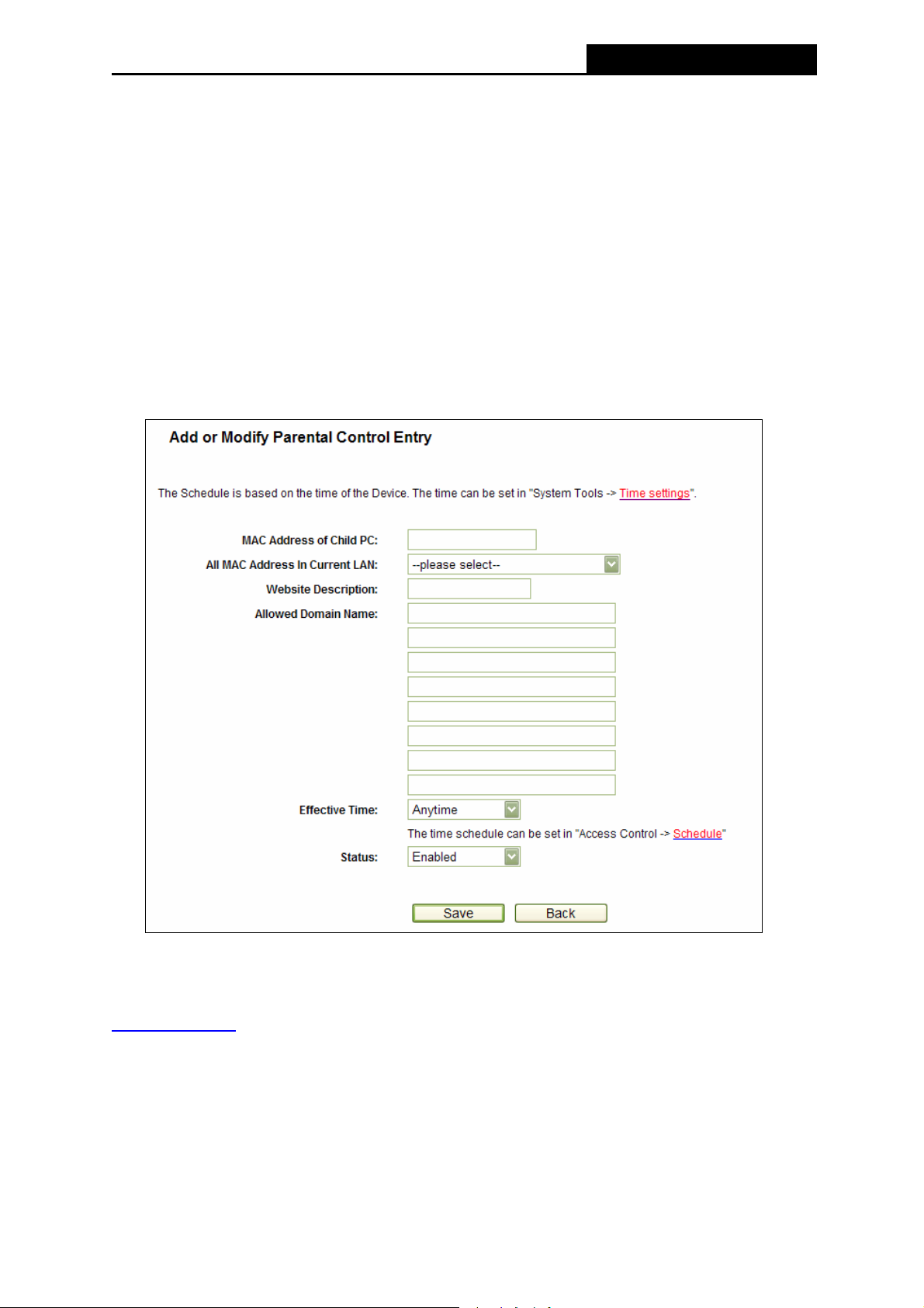
PW-3G401M 3G Wireless N Nano Router
5. Select from the Effective Time drop-down list the schedule (e.g. Schedule_1) you want the
entry to take effect. If there are not suitable schedules for you, click the Schedule in red
below to go to the Advance Schedule Settings page and create the schedule you need.
6. In the Status field, you can select Enabled or Disabled to enable or disable your entry.
7. Click the Save button.
Click the Enable All button to enable all the rules in the list.
Click the Disable All button to disable all the rules in the list.
Click the Delete All button to delete all the entries in the table.
Click the Next button to go to the next page, or click the Previous button return to the previous
page.
Figure 4-48 Add or Modify Parental Control Entry
For example: If you desire that the child PC with MAC address 00-11-22-33-44-AA can access
www.google.com
on Saturday only while the parent PC with MAC address 00-11-22-33-44-BB
is without any restriction, you should follow the settings below.
1. Click “Parental Control” menu on the left to enter the Parental Control Settings page.
Check Enable and enter the MAC address 00-11-22-33-44-BB in the MAC Address of
Parental PC field.
-77-
Page 86

PW-3G401M 3G Wireless N Nano Router
2. Click “Access Control → Schedule” on the left to enter the Schedule Settings page. Click
Add New... button to create a new schedule with Schedule Description is Schedule_1, Day
is Sat and Time is all day-24 hours.
3. Click “Parental Control” menu on the left to go back to the Add or Modify Parental Control
Entry page:
z Click Add New... button.
z Enter 00-11-22-33-44-AA in the MAC Address of Child PC field.
z Enter “Allow Google” in the Website Description field.
z Enter “www.google.com” in the Allowed Domain Name field.
z Select “Schedule_1” you create just now from the Effective Time drop-down list.
z In Status field, select Enable.
4. Click Save to complete the settings.
Then you will go back to the Parental Control Settings page and see the following list, as
shown in Figure 4-49.
Figure 4-49 Parental Control Settings
4.12 Access Control
Figure 4-50 Access Control
There are four submenus under the Access Control menu as shown in Figure 4-50: Rule, Host,
Target and Schedule. Click any of them, and you will be able to configure the corresponding
function.
4.12.1 Rule
Choose menu “Access Control → Rule”, and then you can view and set Access Control rules
in the screen as shown in Figure 4-51.
-78-
Page 87
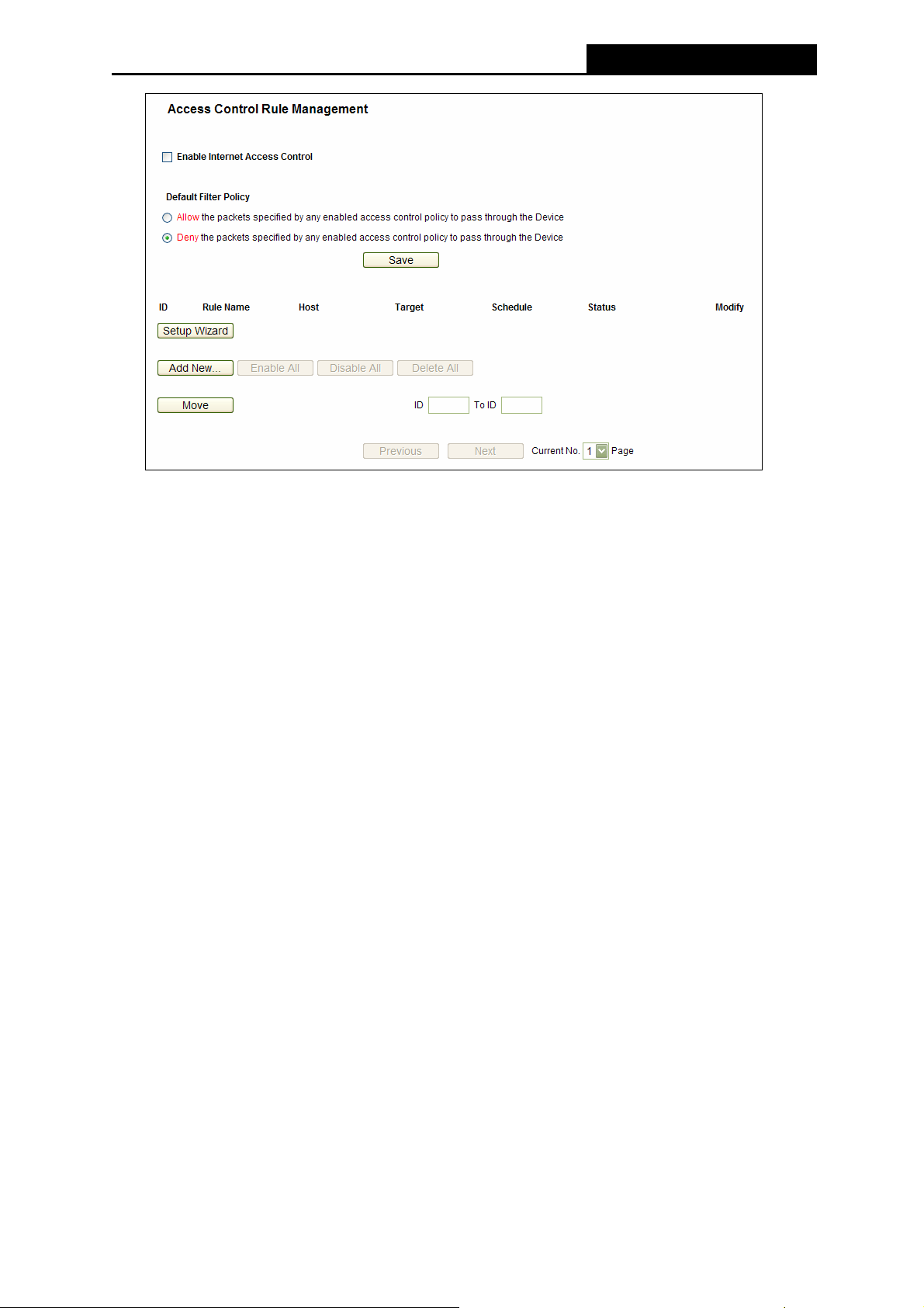
PW-3G401M 3G Wireless N Nano Router
Figure 4-51 Access Control Rule Management
¾ Enable Internet Access Control - Select the check box to enable the Internet Access
Control function, so the Default Filter Policy can take effect.
¾ Rule Name - Here displays the name of the rule and this name is unique.
¾ Host - Here displays the host selected in the corresponding rule.
¾ Target - Here displays the target selected in the corresponding rule.
¾ Schedule - Here displays the schedule selected in the corresponding rule.
¾ Enable - Here displays the status of the rule, enabled or not. Check this option to enable a
specific entry.
¾ Modify - Here you can edit or delete an existing rule.
¾ Setup Wizard - Click the Setup Wizard button to create a new rule entry.
¾ Add New... - Click the Add New... button to add a new rule entry.
¾ Enable All - Click the Enable All button to enable all the rules in the list.
¾ Disable All - Click the Disable All button to disable all the rules in the list.
¾ Delete All - Click the Delete All button to delete all the entries in the table.
¾ Move - You can change the entry’s order as desired. Enter in the first box the ID number of
the entry you want to move and in the second box another ID number, and then click the
Move button to change the entries’ order.
¾ Next - Click the Next button to go to the next page.
¾ Previous - Click the Previous button to return to the previous page.
-79-
Page 88
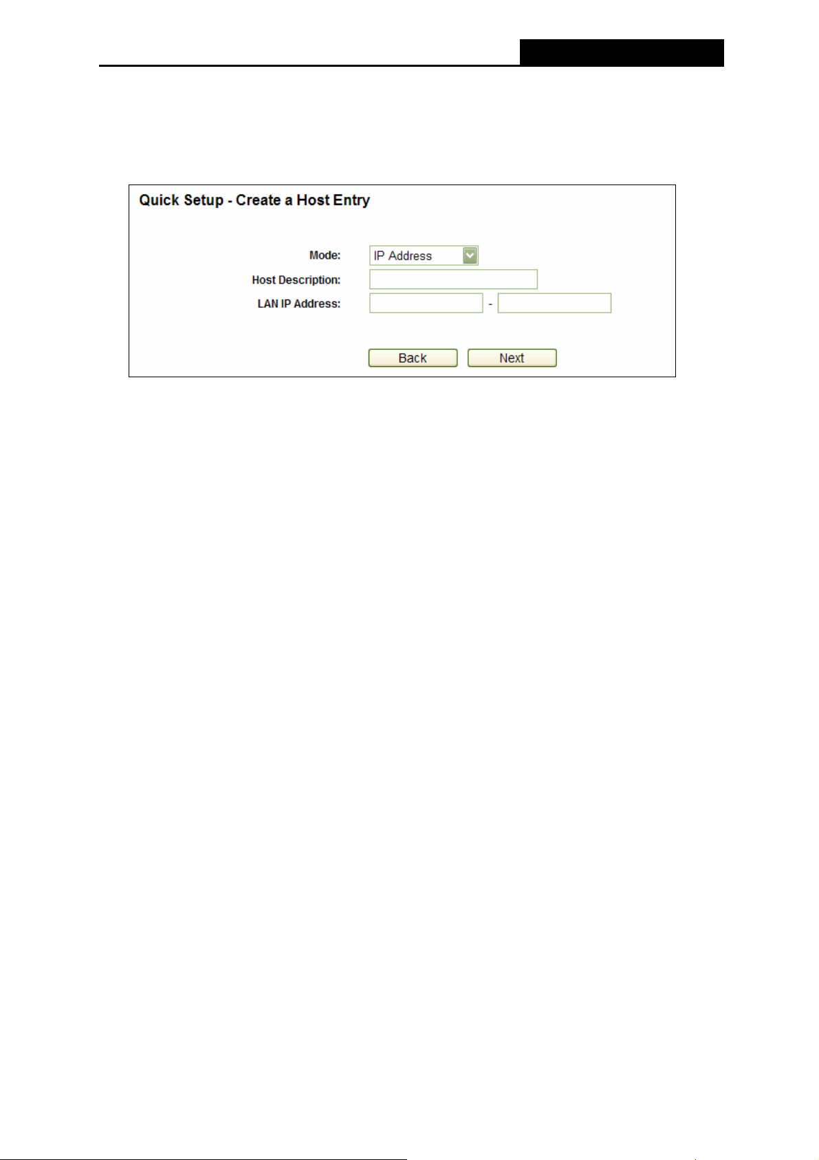
PW-3G401M 3G Wireless N Nano Router
There are two methods to add a new rule.
Method One:
1. Click Setup Wizard button and the next screen will appear as shown in Figure 4-52.
Figure 4-52 Quick Setup – Create a Host Entry
¾ Host Description - In this field, create a unique description for the host (e.g. Host_1).
¾ Mode - Here are two options, IP Address and MAC Address. You can select either of
them from the drop-down list.
If the IP Address is selected, you can see the following item:
¾ LAN IP Address - Enter the IP address or address range of the host in dotted-decimal
format (e.g. 192.168.1.23).
If the MAC Address is selected, you can see the following item:
¾ MAC Address - Enter the MAC address of the host in XX-XX-XX-XX-XX-XX format
(e.g. 00-11-22-33-44-AA).
2. Click Next when finishing creating the host entry, and the next screen will appear as shown
in Figure 4-53.
-80-
Page 89

PW-3G401M 3G Wireless N Nano Router
Figure 4-53 Quick Setup – Create an Access Target Entry
¾ Target Description - In this field, create a description for the target. Note that this
description should be unique (e.g. Target_1).
¾ Mode - Here are two options, IP Address and Domain Name. You can choose either
of them from the drop-down list.
If the IP Address is selected, you will see the following items:
¾ IP Address - Enter the IP address (or address range) of the target (targets) in
dotted-decimal format (e.g. 192.168.1.23).
¾ Target Port - Specify the port or port range for the target. For some common service
ports, you can make use of the Common Service Port item below.
¾ Protocol - Here are four options, All, TCP, UDP, and ICMP. Select one of them from
the drop-down list for the target.
¾ Common Service Port - Here lists some common service ports. Select one from the
drop-down list, and the corresponding port number will be filled in the Target Port field
automatically. For example, if you select "FTP", "21" will be filled in the Target Port
automatically.
If the Domain Name is selected, you will see the following items:
¾ Domain Name - Here you can enter 4 domain names, either the full name or the
keywords (for example, google). Any domain name with keywords in it
(www.google.com, www.google.cn) will be blocked or allowed.
3. Click Next when finishing creating the access target entry, and the next screen will appear
as shown in Figure 4-54.
-81-
Page 90
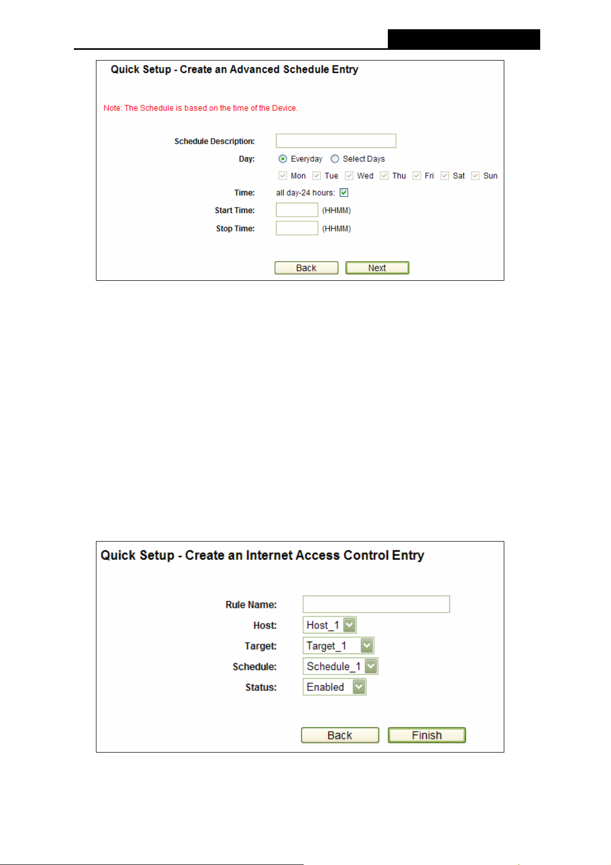
PW-3G401M 3G Wireless N Nano Router
Figure 4-54 Quick Setup – Create an Advanced Schedule Entry
¾ Schedule Description - In this field, create a description for the schedule. Note that
this description should be unique (e.g. Schedule_1).
¾ Day - Choose Select Days and select the certain day (days), or choose Everyday.
¾ Time - Select "24 hours", or specify the Start Time and Stop Time yourself.
¾ Start Time - Enter the start time in HHMM format (HHMM are 4 numbers). For
example 0800 is 8:00.
¾ Stop Time - Enter the stop time in HHMM format (HHMM are 4 numbers). For
example 2000 is 20:00.
4. Click Next when finishing creating the advanced schedule entry, and the next screen will
appear as shown in Figure 4-55.
Figure 4-55 Quick Setup – Create an Internet Access Control Entry
-82-
Page 91

PW-3G401M 3G Wireless N Nano Router
¾ Rule - In this field, create a name for the rule. Note that this name should be unique
(e.g. Rule_1).
¾ Host - In this field, select a host from the drop-down list for the rule. The default value
is the Host Description you set just now.
¾ Target - In this filed, select a target from the drop-down list for the rule. The default
value is the Target Description you set just now.
¾ Schedule - In this field, select a schedule from the drop-down list for the rule. The
default value is the Schedule Description you set just now.
¾ Status - In this field, there are two options, Enable or Disable. Select Enable so that
the rule will take effect. Select Disable so that the rule won't take effect.
5. Click Finish to complete adding a new rule.
Method Two:
1. Click the Add New… button and the next screen will pop up as shown in Figure 4-51.
2. Give a name (e.g. Rule_1) for the rule in the Rule Name field.
3. Select a host from the Host drop-down list or choose “Click Here To Add New Host List”.
4. Select a target from the Target drop-sown list or choose “Click Here To Add New Target
List”.
5. Select a schedule from the Schedule drop-down list or choose “Click Here To Add New
Schedule”.
6. In the Status field, select Enabled or Disabled to enable or disable your entry.
7. Click the Save button.
Figure 4-56 Add Internet Access Control Entry
For example: If you desire to allow the host with MAC address 00-11-22-33-44-AA to access
www.google.com only from 18:00 to 20:00 on Saturday and Sunday, and forbid other hosts in
the LAN to access the Internet, you should follow the settings below:
-83-
Page 92

PW-3G401M 3G Wireless N Nano Router
1. Click the submenu Rule of Access Control in the left to return to the Rule List page.
Select Enable Internet Access Control and choose "Allow the packets specified by any
enabled access control policy to pass through the Router".
2. We recommend that you click Setup Wizard button to finish all the following settings.
3. Click the submenu Host of Access Control in the left to enter the Host List page. Add a
new entry with the Host Description is Host_1 and MAC Address is 00-11-22-33-44-AA.
4. Click the submenu Target of Access Control in the left to enter the Target List page. Add
a new entry with the Target Description is Target_1 and Domain Name is
www.google.com.
5. Click the submenu Schedule of Access Control in the left to enter the Schedule List page.
Add a new entry with the Schedule Description is Schedule_1, Day is Sat and Sun, Start
Time is 1800 and Stop Time is 2000.
6. Click the submenu Rule of Access Control in the left, Click Add New... button to add a
new rule as follows:
• In Rule Name field, create a name for the rule. Note that this name should be unique,
for example Rule_1.
• In Host field, select Host_1.
• In Target field, select Target_1.
• In Schedule field, select Schedule_1.
• In Status field, select Enable.
• Click Save to complete the settings.
Then you will go back to the Access Control Rule Management page and see the following list.
4.12.2 Host
Choose menu “Access Control → Host”, you can view and set a Host list in the screen as
shown in Figure 4-57. The host list is necessary for the Access Control Rule.
Figure 4-57 Host Settings
¾ Host Description - Here displays the description of the host and this description is unique.
¾ Information - Here displays the information about the host. It can be IP or MAC.
¾ Modify - To modify or delete an existing entry.
-84-
Page 93
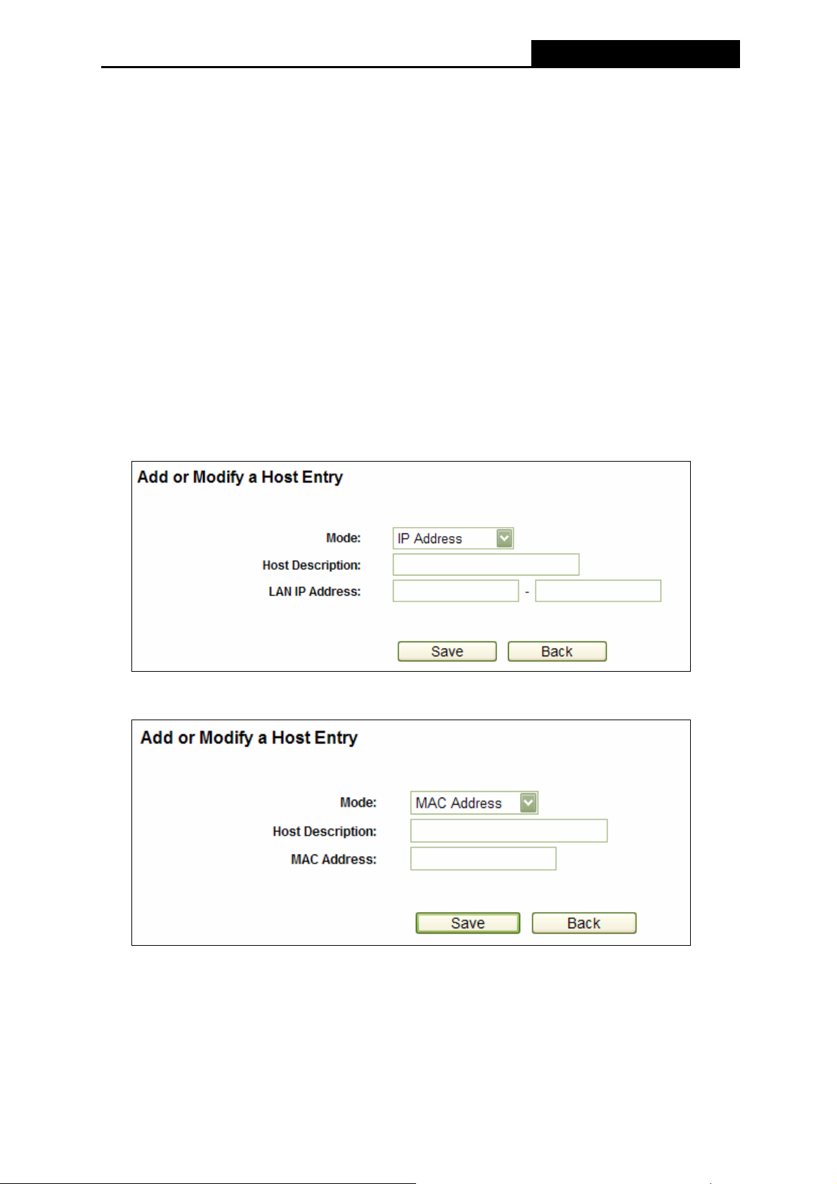
PW-3G401M 3G Wireless N Nano Router
To add a new entry, please follow the steps below.
1. Click the Add New… button.
2. In the Mode field, select IP Address or MAC Address.
z If you select IP Address, the screen shown is Figure 4-58.
1) In Host Description field, create a unique description for the host (e.g. Host_1).
2) In LAN IP Address field, enter the IP address.
z If you select MAC Address, the screen shown is Figure 4-59.
1) In Host Description field, create a unique description for the host (e.g. Host_1).
2) In MAC Address field, enter the MAC address.
3. Click the Save button to complete the settings.
Click the Delete All button to delete all the entries in the table.
Click the Next button to go to the next page, or click the Previous button return to the previous
page.
Figure 4-58 Add or Modify a Host Entry
Figure 4-59 Add or Modify a Host Entry
For example: If you desire to restrict the internet activities of host with MAC address
00-11-22-33-44-AA, you should first follow the settings below:
1. Click Add New... button in Figure 4-57 to enter the Add or Modify a Host Entry page.
2. In Mode field, select MAC Address from the drop-down list.
-85-
Page 94

PW-3G401M 3G Wireless N Nano Router
3. In Host Description field, create a unique description for the host (e.g. Host_1).
4. In MAC Address field, enter 00-11-22-33-44-AA.
5. Click Save to complete the settings.
Then you will go back to the Host Settings page and see the following list.
4.12.3 Target
Choose menu “Access Control → Tar g et”, you can view and set a Target list in the screen as
shown in Figure 4-60. The target list is necessary for the Access Control Rule.
Figure 4-60 Target Settings
Target Description - Here displays the description about the target and this description is
¾
unique.
¾ Information - The target can be IP address, port, or domain name.
¾ Modify - To modify or delete an existing entry.
To add a new entry, please follow the steps below.
1. Click the Add New… button.
2. In Mode field, select IP Address or Domain Name.
z If you select IP Address, the screen shown is Figure 4-61.
1) In Target Description field, create a unique description for the target (e.g.
Target_1).
2) In IP Address field, enter the IP address of the target.
3) Select a common service from Common Service Port drop-down list, so that the
Target Port will be automatically filled. If the Common Service Port drop-down
list doesn’t have the service you want, specify the Target Port manually.
4) In Protocol field, select TCP, UDP, ICMP or ALL.
z If you select Domain Name, the screen shown is Figure 4-62.
1) In Target Description field, create a unique description for the target (e.g.
Target_1).
-86-
Page 95
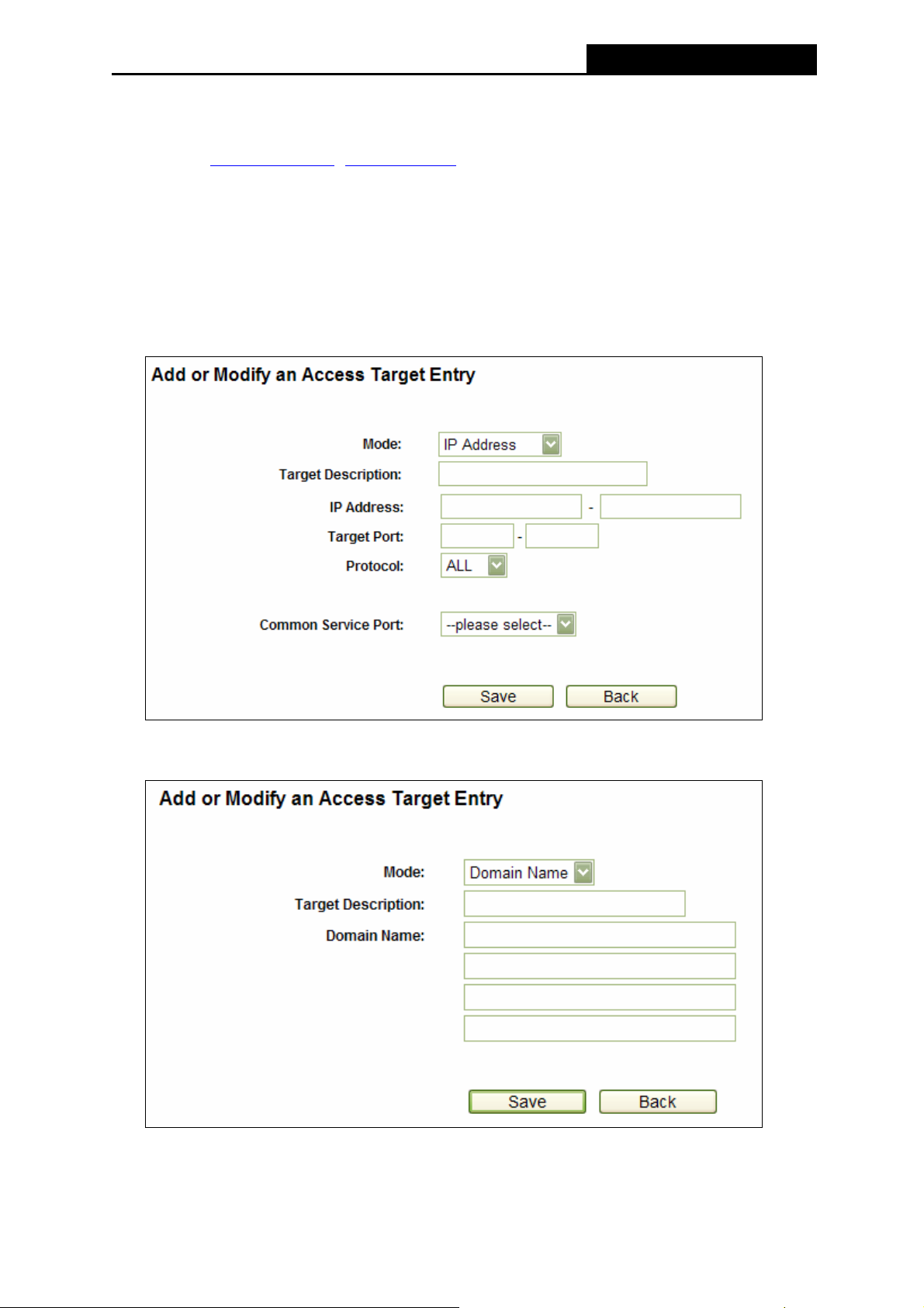
PW-3G401M 3G Wireless N Nano Router
2) In Domain Name field, enter the domain name, either the full name or the
keywords (for example google) in the blank. Any domain name with keywords in it
(www.google.com, www.google.hk) will be blocked or allowed. You can enter 4
domain names.
3. Click the Save button.
Click the Delete All button to delete all the entries in the table.
Click the Next button to go to the next page, or click the Previous button return to the previous
page.
Figure 4-61 Add or Modify an Access Target Entry
Figure 4-62 Add or Modify an Access Target Entry
-87-
Page 96
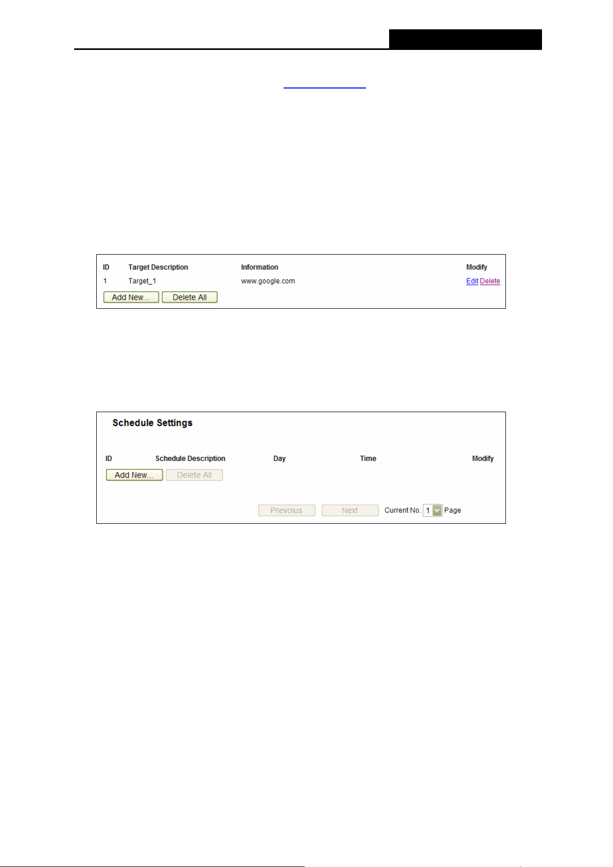
PW-3G401M 3G Wireless N Nano Router
For example: If you desire to restrict the internet activities of host with MAC address
00-11-22-33-44-AA in the LAN to access www.google.com
only, you should first follow the
settings below:
1. Click Add New… button in Figure 4-60 to enter the Add or Modify an Access Target
Entry page.
2. In Mode field, select Domain Name from the drop-down list.
3. In Target Description field, create a unique description for the target (e.g. Target_1).
4. In Domain Name field, enter www.google.com.
5. Click Save to complete the settings.
Then you will go back to the Target Settings page and see the following list.
4.12.4 Schedule
Choose menu “Access Control → Schedule”, you can view and set a Schedule list in the
next screen as shown in Figure 4-63. The Schedule list is necessary for the Access Control
Rule.
Figure 4-63 Schedule Settings
¾ Schedule Description - Here displays the description of the schedule and this description
is unique.
¾ Day - Here displays the day(s) in a week.
¾ Time - Here displays the time period in a day.
¾ Modify - Here you can edit or delete an existing schedule.
To add a new schedule, follow the steps below.
1. Click Add New... button shown in Figure 4-63 and the next screen will pop-up as shown in
Figure 4-64.
2. In Schedule Description field, create a unique description for the schedule (e.g.
Schedule_1).
3. In Day field, select the day or days you need.
-88-
Page 97
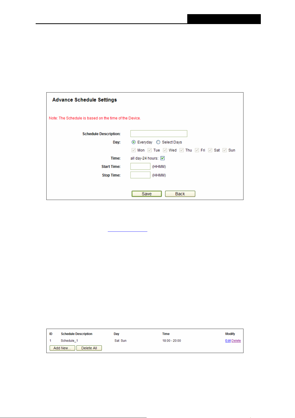
PW-3G401M 3G Wireless N Nano Router
4. In Time field, you can select all day-24 hours or you may enter the Start Time and Stop
Time in the corresponding field.
5. Click Save to complete the settings.
Click the Delete All button to delete all the entries in the table.
Click the Next button to go to the next page, or click the Previous button return to the previous
page.
Figure 4-64 Advanced Schedule Settings
For example: If you desire to restrict the internet activities of host with MAC address
00-11-22-33-44-AA to access www.google.com
only from 18:00 to 20:00 on Saturday and
Sunday, you should first follow the settings below:
1. Click Add New... button shown in Figure 4-63 to enter the Advanced Schedule Settings
page.
2. In Schedule Description field, create a unique description for the schedule (e.g.
Schedule_1).
3. In Day field, check the Select Days radio button and then select Sat and Sun.
4. In Time field, enter 1800 in Start Time field and 2000 in Stop Time field.
5. Click Save to complete the settings.
Then you will go back to the Schedule Settings page and see the following list.
-89-
Page 98

PW-3G401M 3G Wireless N Nano Router
4.13 Advanced Routing
Figure 4-65 Advanced Routing
There are two submenus under the Advanced Routing menu as shown in Figure 4-65: Static
Routing List and System Routing Table. Click any of them, and you will be able to configure
the corresponding function.
4.13.1 Static Routing List
Choose menu “Advanced Routing → Static Routing List”, you can configure the static route
in the next screen (shown in Figure 4-66). A static route is a pre-determined path that network
information must travel to reach a specific host or network.
Figure 4-66 Static Routing
To add static routing entries:
1. Click Add New… shown in Figure 4-66, you will see the following screen.
Figure 4-67 Add or Modify a Static Route Entry
-90-
Page 99
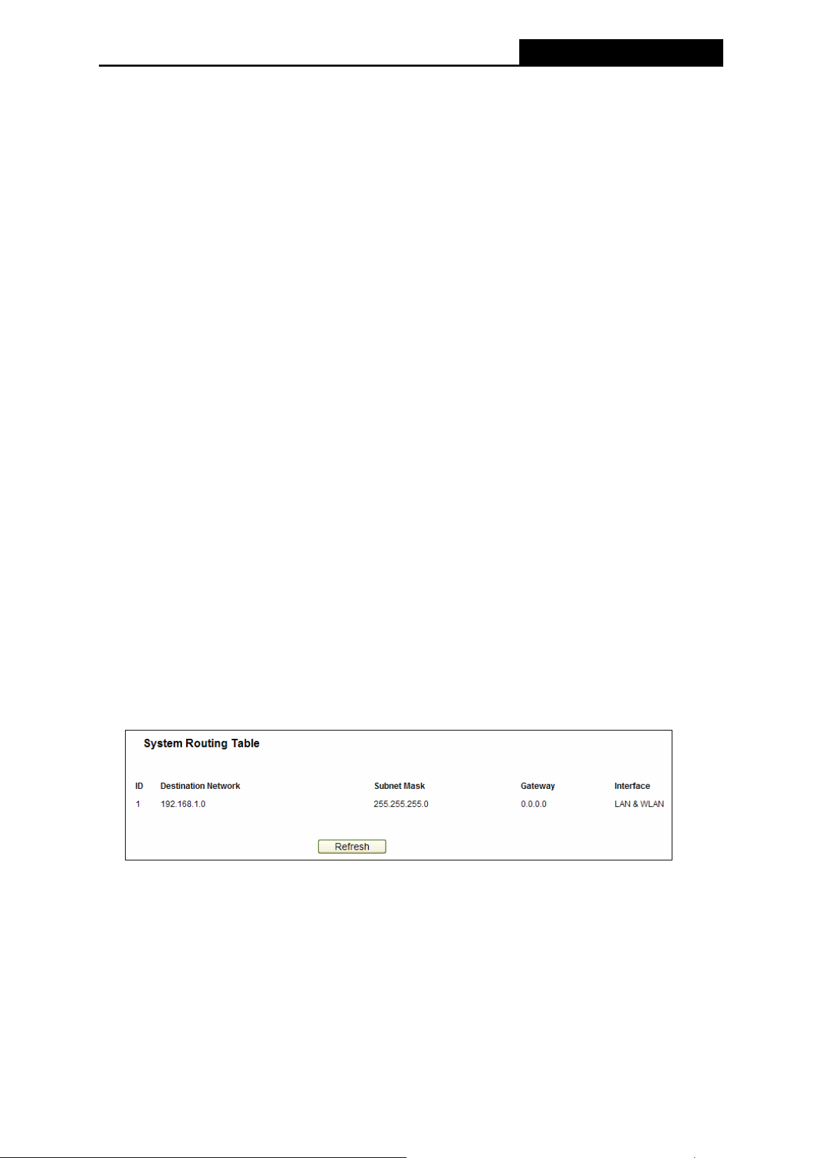
PW-3G401M 3G Wireless N Nano Router
2. Enter the following data:
¾ Destination Network - The Destination Network is the address of the network or host
that you want to assign to a static route.
¾ Subnet Mask - The Subnet Mask determines which portion of an IP Address is the
network portion, and which portion is the host portion.
¾ Gateway - This is the IP Address of the gateway device that allows for contact between
the Router and the network or host.
3. Select Enabled or Disabled for this entry on the Status pull-down list.
4. Click the Save button to make the entry take effect.
Other configurations for the entries:
Click the Delete button to delete the entry.
Click the Enable All button to enable all the entries.
Click the Disable All button to disable all the entries.
Click the Delete All button to delete all the entries.
Click the Previous button to view the information in the previous screen, click the Next button
to view the information in the next screen.
4.13.2 System Routing Table
Choose menu “Advanced Routing → System Routing Table”, you can configure the system
routing table in the next screen (shown in Figure 4-68). System routing table views all of the
valid route entries in use.
Figure 4-68 System Routing Table
¾ Destination Network - The Destination Network is the address of the network or host to
which the static route is assigned.
¾ Subnet Mask - The Subnet Mask determines which portion of an IP address is the network
portion, and which portion is the host portion.
¾ Gateway - This is the IP address of the gateway device that allows for contact between the
Router and the network or host.
-91-
Page 100

PW-3G401M 3G Wireless N Nano Router
¾ Interface - This interface tells you whether the Destination IP Address is on the LAN &
WLAN (internal wired and wireless networks), the WAN (Internet).
4.14 Bandwidth Control
Figure 4-69 Bandwidth Control
There are two submenus under the Bandwidth Control menu as shown in Figure 4-69: Control
Settings and Rules List. Click any of them, and you will be able to configure the corresponding
function. The detailed explanations for each submenu are provided below.
4.14.1 Control Settings
Choose menu “Bandwidth Control → Control Settings”, you can configure the Egress
Bandwidth and Ingress Bandwidth in the next screen. Their values you configure should be less
than 100000Kbps. For optimal control of the bandwidth, please select the right Line Type and
ask your ISP for the total bandwidth of the egress and ingress.
Figure 4-70 Bandwidth Control Settings
¾ Enable Bandwidth Control - Check this box so that the Bandwidth Control settings can
take effect.
¾ Line Type - Select the right type for you network connection. If you don’t know how to
choose, please ask your ISP for the information.
¾ Egress Bandwidth - The upload speed through the WAN port.
¾ Ingress Bandwidth - The download speed through the WAN port.
4.14.2 Rules List
Choose menu “Bandwidth Control → Rules List”, you can view and configure the Bandwidth
Control rules in the Figure 4-71.
-92-
 Loading...