


iSCSI GbE to SAS/SATA II
RAID Subsystem
User Manual
Revision 1.0

iSCSI GbE to SAS/SATA II RAID Subsystem
2
User Manual
Table of Contents
Preface ................................................................................................................................ 6
Before You Begin ............................................................................................................. 7
Safety Guidelines ............................................................................................................................................................ 7
Controller Configurations ........................................................................................................................................... 7
Packaging, Shipment and Delivery ...................................................................................................................... 7
Chapter 1 Introduction ................................................................................................. 9
1.1 Technical Specifications ...................................................................................................................................... 11
1.2 Terminology ............................................................................................................................................................ 13
1.3 RAID Levels .............................................................................................................................................................. 15
1.4 Volume Relationship Diagram ......................................................................................................................... 16
Chapter 2 Identifying Parts of the RAID Subsystem ........................................... 17
2.1 Main Components ................................................................................................................................................ 17
2.1.2 Front View ........................................................................................................................................................ 17
2.1.2.1 Disk Trays ................................................................................................................................................. 18
2.1.2.2 LCD Front Panel ..................................................................................................................................... 19
2.1.2 Rear View ......................................................................................................................................................... 21
2.2 Controller Module ................................................................................................................................................ 22
2.2.1 Controller Module Panel ............................................................................................................................ 23
2.3 Power Supply / Fan Module (PSFM) ............................................................................................................. 24
2.3.1 PSFM Panel ...................................................................................................................................................... 25
2.4 Checklist before Starting ................................................................................................................................... 26
Chapter 3 Getting Started with the Subsystem .................................................... 28
3.1 Connecting the iSCSI RAID Subsystem to the Network ....................................................................... 28
3.2 Powering On ........................................................................................................................................................... 28
3.3 Disk Drive Installation ......................................................................................................................................... 29
3.3.1 Installing a SAS Disk Drive in a Disk Tray .......................................................................................... 29
3.3.2 Installing a SATA Disk Drive (Dual Controller Mode) in a Disk Tray ...................................... 32
3.4 iSCSI Introduction ................................................................................................................................................. 35
Chapter 4 Quick Setup ............................................................................................... 37

iSCSI GbE to SAS/SATA II RAID Subsystem
User Manual
3
4.1 Management Interfaces ...................................................................................................................................... 37
4.1.1 Serial Console Port ....................................................................................................................................... 37
4.1.2 Remote Control – Secure Shell ............................................................................................................... 37
4.1.3 LCD Control Module (LCM) ...................................................................................................................... 38
4.1.4 Web GUI ........................................................................................................................................................... 40
4.2 How to Use the System Quickly ..................................................................................................................... 42
4.2.1 Quick Installation .......................................................................................................................................... 42
4.2.2 Volume Creation Wizard ............................................................................................................................ 45
Chapter 5 Configuration ............................................................................................ 47
5.1 Web GUI Management Interface Hierarchy ............................................................................................... 47
5.2 System Configuration .......................................................................................................................................... 49
5.2.1 System Setting ............................................................................................................................................... 49
5.2.2 Network Setting ............................................................................................................................................. 50
5.2.3 Login Setting ................................................................................................................................................... 51
5.2.4 Mail Setting ..................................................................................................................................................... 52
5.2.5 Notification Setting ...................................................................................................................................... 53
5.3 iSCSI Configuration .............................................................................................................................................. 55
5.3.1 NIC ...................................................................................................................................................................... 55
5.3.2 Entity Property ................................................................................................................................................ 59
5.3.3 Node ................................................................................................................................................................... 60
5.3.4 Session ............................................................................................................................................................... 63
5.3.5 CHAP Account ................................................................................................................................................ 64
5.4 Volume Configuration ......................................................................................................................................... 65
5.4.1 Physical Disk .................................................................................................................................................... 65
5.4.2 RAID Group ..................................................................................................................................................... 68
5.4.3 Virtual Disk....................................................................................................................................................... 71
5.4.4 Snapshot ........................................................................................................................................................... 75
5.4.5 Logical Unit ...................................................................................................................................................... 78
5.4.6 Example ............................................................................................................................................................. 79
5.5 Enclosure Management ...................................................................................................................................... 84
5.5.1 Hardware Monitor ........................................................................................................................................ 85
5.5.2 UPS ...................................................................................................................................................................... 86
5.5.3 SES ....................................................................................................................................................................... 88

iSCSI GbE to SAS/SATA II RAID Subsystem
4
User Manual
5.5.4 Hard Drive S.M.A.R.T. Support ................................................................................................................. 88
5.6 System Maintenance ........................................................................................................................................... 90
5.6.1 System Information ...................................................................................................................................... 90
5.6.2 Event Log .......................................................................................................................................................... 91
5.6.3 Upgrade ............................................................................................................................................................ 92
5.6.4 Firmware Synchronization ......................................................................................................................... 93
5.6.5 Reset to Factory Default ............................................................................................................................ 93
5.6.6 Import and Export ........................................................................................................................................ 94
5.6.7 Reboot and Shutdown ................................................................................................................................ 94
5.7 Home/Logout/Mute ............................................................................................................................................. 95
5.7.1 Home ................................................................................................................................................................. 95
5.7.2 Logout ............................................................................................................................................................... 95
5.7.3 Mute ................................................................................................................................................................... 95
Chapter 6 Advanced Operations .............................................................................. 96
6.1 Volume Rebuild ..................................................................................................................................................... 96
6.2 RG Migration........................................................................................................................................................... 98
6.3 VD Extension ......................................................................................................................................................... 100
6.4 Snapshot / Rollback ........................................................................................................................................... 101
6.4.1 Create Snapshot Volume ......................................................................................................................... 102
6.4.2 Auto Snapshot.............................................................................................................................................. 104
6.4.3 Rollback ........................................................................................................................................................... 105
6.5 Disk Roaming........................................................................................................................................................ 106
6.6 VD Clone ................................................................................................................................................................ 106
6.7 SAS JBOD Expansion ......................................................................................................................................... 113
6.7.1 Connecting JBOD ........................................................................................................................................ 113
6.8 MPIO and MC/S .................................................................................................................................................. 117
6.9 Trunking and LACP ............................................................................................................................................. 119
6.10 Dual Controllers ................................................................................................................................................ 121
6.10.1 Perform I/O ................................................................................................................................................. 121
6.10.2 Ownership .................................................................................................................................................... 122
6.10.3 Controller Status ....................................................................................................................................... 122
6.11 QReplica (Optional) ......................................................................................................................................... 124

iSCSI GbE to SAS/SATA II RAID Subsystem
User Manual
5
Chapter 7 Troubleshooting .................................................................................... 134
7.1 System Buzzer ...................................................................................................................................................... 134
7.2 Event Notifications ............................................................................................................................................. 134
Appendix ....................................................................................................................... 144
A. Certification list ...................................................................................................................................................... 144
B. Microsoft iSCSI initiator ...................................................................................................................................... 148

iSCSI GbE to SAS/SATA II RAID Subsystem
6
User Manual
Preface
About this manual
This manual provides information regarding the quick installation and hardware
features of the RAID subsystem. This document also describes how to use the
storage management software. Information contained in the manual has been
reviewed for accuracy, but not for product warranty because of the various
environment/OS/settings. Information and specifications will be changed without
further notice.
This manual uses section numbering for every topics being discussed for easy and
convenient way of finding information in accordance with the user’s needs. The
following icons are being used for some details and information to be con sidered in
going through with this manual:
Copyright
No part of this publication may be reproduced, stored in a retrieval system, or
transmitted in any form or by any means, electronic, mechanical, photocopying,
recording or otherwise, without the prior written consent.
Trademarks
All products and trade names used in this document are trademarks or registered
trademarks of their respective holders.
Changes
The material in this document is for information only and is subject to change without
notice.
IMPORTANT!
These are the important information that the user must
remember.
WARNING!
These are the warnings that the user must follow to avoid
unnecessary errors and bodily injury during hardware and
software operation of the subsystem.
CAUTION:
These are the cautions that user must be aware to
prevent damage to the equipment and its components.
NOTES:
These are notes that contain useful information and tips
that the user must give attention to in going through
with the subsystem operation.

iSCSI GbE to SAS/SATA II RAID Subsystem
User Manual
7
Before You Begin
Before going through with this manual, you should read and focus to the following
safety guidelines. Notes about the subsystem’s controller configuration and the
product packaging and delivery are also included.
Safety Guidelines
To provide reasonable protection against any harm on the part of the user and to
obtain maximum performance, user is advised to be aware of the following safety
guidelines particularly in handling hardware components:
Upon receiving of the product:
Place the product in its proper location.
To avoid unnecessary dropping out, make sure that somebody is around for
immediate assistance.
It should be handled with care to avoid dropping that may cause damage to the
product. Always use the correct lifting procedures.
Upon installing of the product:
Ambient temperature is very important for the installation site. It must not
exceed 30
◦
C. Due to seasonal climate changes; regulate the installation site
temperature making it not to exceed the allowed ambient temperature.
Before plugging-in any power cords, cables and connectors, make sure that the
power switches are turned off. Disconnect first any power connection if the power
supply module is being removed from the enclosure.
Outlets must be accessible to the equipment.
All external connections should be made using shielded cables and as much as
possible should not be performed by bare hand. Using anti-static hand gloves is
recommended.
In installing each component, secure all the mounting screws and locks. Make
sure that all screws are fully tightened. Follow correctly all the liste d procedures
in this manual for reliable performance.
Controller Configurations
This RAID subsystem supports single controller configuration.
Packaging, Shipment and Delivery
Before removing the subsystem from the shipping carton, you should visually
inspect the physical condition of the shipping carton.
Unpack the subsystem and verify that the contents of the shipping carton are all
there and in good condition.
Exterior damage to the shipping carton may indicate that the contents of the
carton are damaged.
If any damage is found, do not remove the components; contact the dealer where
you purchased the subsystem for further instructions.

iSCSI GbE to SAS/SATA II RAID Subsystem
8
User Manual
The shipping package contains the following:
NOTE: If any damage is found, contact the dealer or vendor for assistance.
iSCSI RAID Subsystem Unit
Two (2) power cords
Five (5) Ethernet LAN cables for single
controller
Note: Ten (10) Ethernet LAN cables for
dual controller
One (1) External null modem cable
Note: Two (2) External null modem cables
for dual controller
User Manual

iSCSI GbE to SAS/SATA II RAID Subsystem
User Manual
9
Chapter 1 Introduction
The iSCSI RAID Subsystem
The EP-3164 series RAID subsystem features four Gigabit ports on each controller to
increase system efficiency and performance. It features high capacity expansion, with 16
hot-swappable SAS/SATA II hard disk drive bays in a 19-inch 3U rackmount unit, scaling
to a maximum storage capacity in the terabyte range. The EP-3164D series also
supports Dual-active controllers which provide better fault tolerance and higher reliability
of system operation.
Unparalleled Performance & Reliability
Supports Dual-active controllers
Front-end 4/8 x 1Gb iSCSI
Supports 802.3ad port trunking, Link Aggregation Control Protocol (LACP)
High data bandwidth of system architecture by powerful 64-bit RAID processor
Unsurpassed Data Availability
RAID 6 capability provides the highest level of data protection
Supports snapshot-on-the-box w/o relying on host software
Supports Microsoft Windows Volume Shadow Copy Services (VSS)
Exceptional Manageability Menu-driven front panel display
Management GUI via serial console, SSH telnet, Web and secure web(HTTPS)
Event notification via Email and SNMP trap
Menu-driven front panel display

iSCSI GbE to SAS/SATA II RAID Subsystem
10
User Manual
Features
Front-end 4/8 x 1Gb ports support independent access, fail-over and load-
balancing
(802.3ad port trunking, LACP)
Supports iSCSI jumbo frame
Supports Microsoft Multipath I/O (MPIO)
Supports RAID levels 0, 1, 0+1, 3, 5, 6, 10, 30, 50, 60 and JBOD
Local N-way mirror: Extension to RAID 1 level, N copies of the disk
Global and dedicated hot spare disks
Write-through or write-back cache policy for different application usage
Supports greater than 2TB per volume set (64-bit LBA support)
Supports manual or scheduling volume snapshot (up to 32 snapshot)
Snapshot rollback mechanism
On-line volume migration with no system down-time
Online volume expansion
Instant RAID volume availability and background initialization
Supports S.M.A.R.T, NCQ and OOB Staggered Spin-up capable drives

iSCSI GbE to SAS/SATA II RAID Subsystem
User Manual
11
1.1 Technical Specifications
Model EP-3164S1/D1-G1S3
RAID Controller iSCSI-SAS
Controller Single / Dual (Redundant)
Host Interface Four / Eight 1Gb/s Ethernet
Disk Interface SAS 3Gb or SATA II
SAS expansion 4x mini SAS (3Gb/s)
Processor Type Intel IOP342 64-bit (Chevelon dual core)
Cache Memory 2GB~4GB /4GB~8GB DDR-II ECC SDRAM
Battery Backup Optional Hot Pluggable BBM
Management Port support Yes
Monitor Port support Yes
UPS connection Yes
RAID level
0, 1, 0+1, 3, 5, 6, 10, 30, 50, 60 and
JBOD
Logical volume Up to 1024
iSCSI Jumbo frame support Yes
Supports Microsoft Multipath I/O
Yes
802.3ad Port Trunking, LACP Support Yes
Host connection Up to 32
Host clustering Up to 16 for one logical volu me
Manual/scheduling volume snapshot Up to 32
Hot spare disks Global and dedicated
Host access control Read-Write & Read-Only
Online Volume Migration Yes
Online Volume sets expansion Yes
Configurable stripe size Yes
Auto volume rebuild Yes
N-way mirror (N copies of the disk) Yes
Microsoft Windows Volume Shadow
Copy Services (VSS)
Yes
Supports CHAP authentication Yes
S.M.A.R.T. support Yes

iSCSI GbE to SAS/SATA II RAID Subsystem
12
User Manual
Snapshot rollback mechanism support Yes
Platform Rackmount
Form Factor 3U
# of Hot Swap Trays 16
Tray Lock Yes
Disk Status Indicator Access / Fail LED
Backplane SAS2 / SATA3 Single BP
# of PS/Fan Modules 460W x 2 w/PFC
# of Fans 2
Power requirements
AC 90V ~ 264V Full Range, 10A ~ 5A,
47Hz ~ 63Hz
Relative Humidity 10% ~ 85% Non-condensing
Operating Temperature 10°C ~ 40°C (50°F ~ 104°F)
Physical Dimension 555(L) x 482(W) x 131(H) mm
Weight (Without Disk) 19/20.5 Kg
Specification is subject to change without notice.

iSCSI GbE to SAS/SATA II RAID Subsystem
User Manual
13
1.2 Terminology
The document uses the following terms:
RAID Redundant Array of Independent Disks. There are different
RAID levels with different degree of data protection, data
availability, and performance to host environment.
PD The Physical Disk belongs to the member disk of one specific
RAID group.
RG Raid Group. A collection of removable media. One RG consists
of a set of VDs and owns one RAID level attribute.
VD Virtual Disk. Each RD could be divided into several VDs. The
VDs from one RG have the same RAID level, but may have
different volume capacity.
LUN Logical Unit Number. A logical unit number (LUN) is a unique
identifier which enables it to differentiate among separate
devices (each one is a logical unit).
GUI Graphic User Interface.
RAID cell When creating a RAID group with a compound RAID level, such
as 10, 30, 50 and 60, this field indicates the number of
subgroups in the RAID group. For example, 8 disks can be
grouped into a RAID group of RAID 10 with 2 cells, 4 cells. In
the 2-cell case, PD {0, 1, 2, 3} forms one RAID 1 subgroup and
PD {4, 5, 6, 7} forms another RAID 1 subgroup. In the 4-cells,
the 4 subgroups are PD {0, 1}, PD {2, 3}, PD {4, 5} and PD
{6,7}.
WT Write-Through cache-write policy. A caching technique in which
the completion of a write request is not signaled until data is
safely stored in non-volatile media. Each data is synchronized in
both data cache and accessed physical disks.
WB Write-Back cache-write policy. A caching technique in which th e
completion of a write request is signaled as soon as the data is
in cache and actual writing to non-volatile media occurs at a
later time. It speeds up system write performance but needs to
bear the risk where data may be inconsistent between data
cache and the physical disks in one short time interval.
RO Set the volume to be Read-Only.
DS Dedicated Spare disks. The spare disks are only used by one
specific RG. Others could not use these dedicated spare disks
for any rebuilding purpose.
GS Global Spare disks. GS is shared for rebuilding purpose. If some
RGs need to use the global spare disks for rebuilding, they could
get the spare disks out from the common spare disks pool for
such requirement.

iSCSI GbE to SAS/SATA II RAID Subsystem
14
User Manual
DG DeGraded mode. Not all of the array’s member disks are
functioning, but the array is able to respond to application read
and write requests to its virtual disks.
SCSI Small Computer Systems Interface.
SAS Serial Attached SCSI.
S.M.A.R.T. Self-Monitoring Analysis and Reporting Technology.
WWN World Wide Name.
HBA Host Bus Adapter.
SES SCSI Enclosure Services.
NIC Network Interface Card.
BBM Battery Backup Module
iSCSI Internet Small Computer Systems Interface.
LACP Link Aggregation Control Protocol.
MPIO Multi-Path Input/Output.
MC/S Multiple Connections per Session
MTU Maximum Transmission Unit.
CHAP
Challenge Handshake Authentication Protocol. An optional
security mechanism to control access to an iSCSI storage
system over the iSCSI data ports.
iSNS Internet Storage Name Service.
SBB Storage Bridge Bay. The objective of the Storage Bridge Bay
Working Group (SBB) is to create a specification that defines
mechanical, electrical and low-level enclosure management
requirements for an enclosure controller slot that will support a
variety of storage controllers from a variety of independent
hardware vendors (“IHVs”) and system vendors.
Dongle Dongle board is for SATA II disk connection to the backplane.

iSCSI GbE to SAS/SATA II RAID Subsystem
User Manual
15
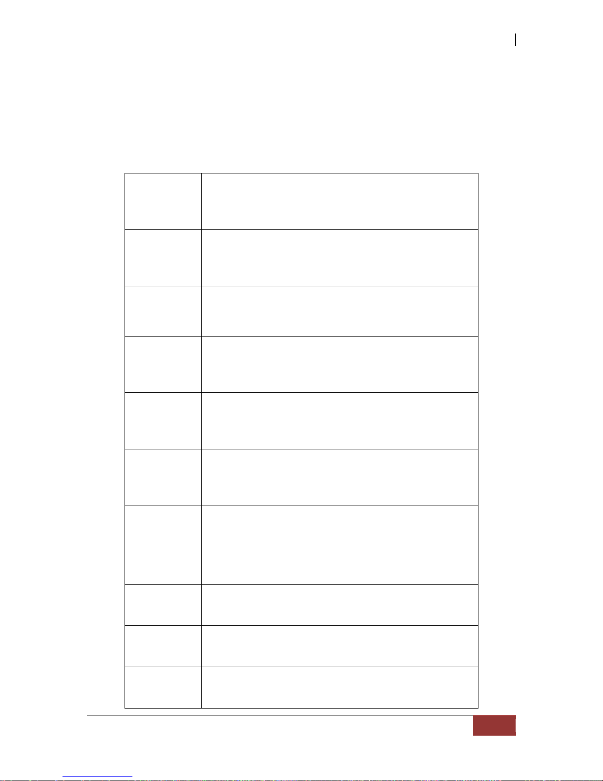
1.3 RAID Levels
The subsystem can implement several different levels of RAID technology. RAID levels
supported by the subsystem are shown below.
RAID Level Description
Min. Drives
0
Block striping is provide, which yields higher
performance than with individual drives. There
is no redundancy.
1
1
Drives are paired and mirrored. All data is 100%
duplicated on an equivalent drive. Fully
redundant.
2
N-way
mirror
Extension to RAID 1 level. It has N copies of the
disk.
N
3
Data is striped across several physical drives.
Parity protection is used for data redundancy.
3
5
Data is striped across several physical drives.
Parity protection is used for data redundancy.
3
6
Data is striped across several physical drives.
Parity protection is used for data redundancy.
Requires N+2 drives to implement because of
two-dimensional parity scheme
4
0 + 1
Mirroring of the two RAID 0 disk arrays. This
level provides striping and redundancy through
mirroring.
4
10
Striping over the two RAID 1 disk arrays. This
level provides mirroring and redundancy
through striping.
4
30
Combination of RAID levels 0 and 3. This level is
best implemented on two RAID 3 disk arrays
with data striped across both disk arrays.
6
50
RAID 50 provides the features of both RAID 0
and RAID 5. RAID 50 includes both parity and
disk striping across multiple drives. RAID 50 is
best implemented on two RAID 5 disk arrays
with data striped across both disk arrays.
6
60
RAID 60 provides the features of both RAID 0
and RAID 6. RAID 60 includes both parity and
disk striping across multiple drives. RAID 60 is
best implemented on two RAID 6 disk arrays
with data striped across both disk arrays.
8
JBOD
The abbreviation of “Just a Bunch Of Disks”.
JBOD needs at least one hard drive.
1

iSCSI GbE to SAS/SATA II RAID Subsystem
16
User Manual
1.4 Volume Relationship Diagram
This is the design of volume structure of the iSCSI RAID subsyst em. It describes the
relationship of RAID components. One RG (RAID Group) is composed of several PDs
(Physical Disks). One RG owns one RAID level attribute. Each RG can be divided into
several VDs (Virtual Disks). The VDs in one RG share the same RAID level, but may have
different volume capacity. Each VD will be associated with the Global Cache Volume to
execute the data transaction. LUN (Logical Unit Number) is a unique identifier, in which
users can access through SCSI commands.

iSCSI GbE to SAS/SATA II RAID Subsystem
User Manual
17
Chapter 2 Identifying Parts of the RAID Subsystem
The illustrations below identify the various parts of the subsystem.
2.1 Main Components
2.1.2 Front View
iSCSI GbE to SAS/SATA II RAID Subsystem
18
User Manual
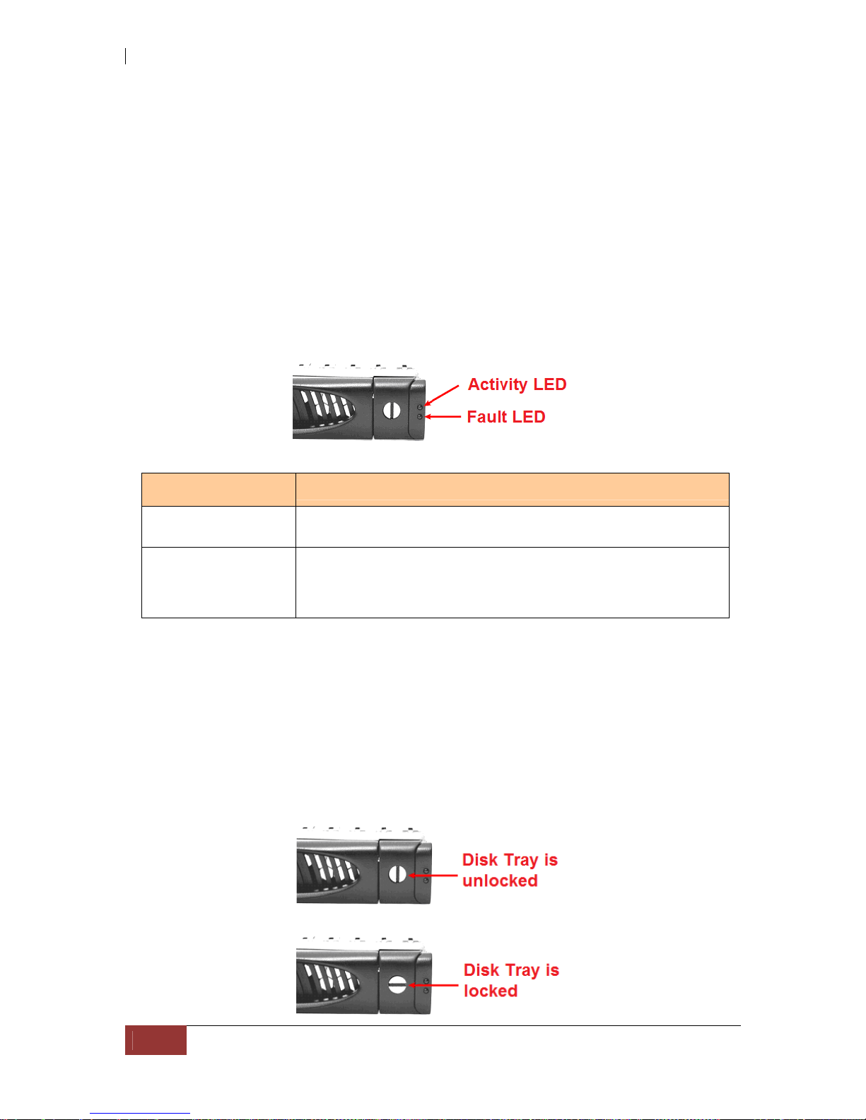
2.1.2.1 Disk Trays
HDD Status Indicator
Part
Function
HDD Activity LED
This LED will blink blue when the hard drive is being accessed.
HDD Fault LED
Green LED indicates power is on and hard drive status is good
for this slot. If hard drive is defective or failed, the LED is Red.
LED is off when there is no hard drive.
Lock Indicator
Every Disk Tray is lockable and is fitted with a lock indicator to indicate
whether or not the tray is locked into the chassis or not. Each tray is also fitted with
an ergonomic handle for easy tray removal.
When the Lock Groove is horizontal, this indicates that the Disk Tray is locked. When
the Lock Groove is vertical, then the Disk Tray is unlocked.
iSCSI GbE to SAS/SATA II RAID Subsystem
User Manual
19
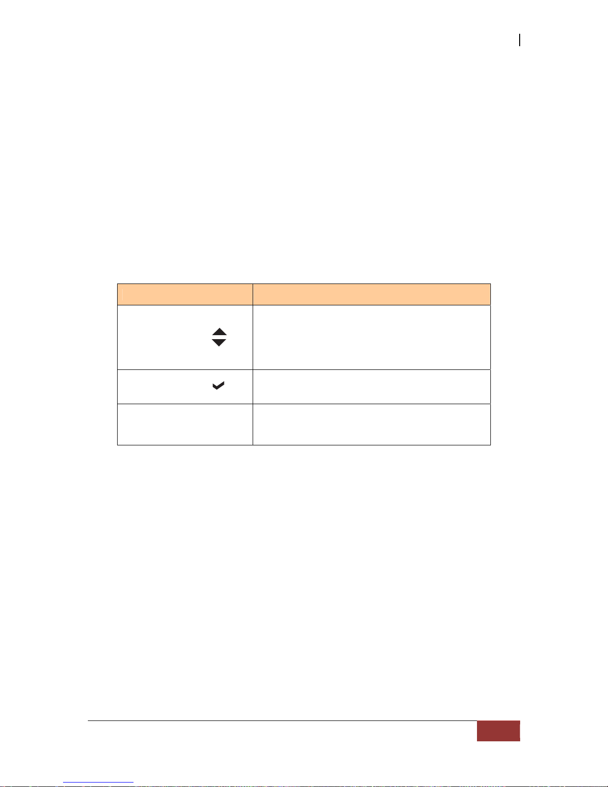
2.1.2.2 LCD Front Panel
Smart Function Front Panel
The smar t LCD panel is a n o p t i o n to c onfigu re the RA ID subsyst em. If yo u are
configuring the subsystem using the LCD panel, press the Select button to login and
configure the RAID subsystem.
Parts Function
Up and Down
Arrow buttons
Use the Up or Down arrow keys to go through
the information on the LCD screen. This is also
used to move between each menu when you
configure the subsystem.
Select button
This is used to enter the option you have
selected.
Exit button EXIT
Press this button to return to the previous
menu.
iSCSI GbE to SAS/SATA II RAID Subsystem
20
User Manual
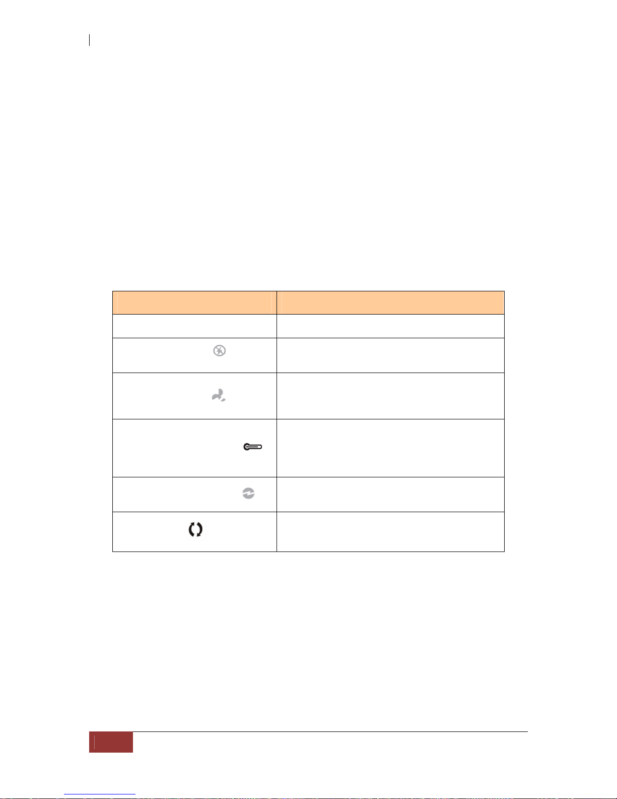
Environment Status LEDs
Parts Function
Power LED Green LED indicates power is ON.
Power Fail LED
If a redundant power supply unit fails, this
LED will turn to RED and alarm will sound.
Fan Fail LED
When a fan fails or the fan’s rotational speed
is below 1500RPM, this LED will turn red and
an alarm will sound.
Over Temperature LED
If temperature irregularities in the system
occurs (HDD slot temperature over 65°C,
Controller temperature over 70°C), this LED
will turn RED and alarm will sound.
Voltage Warning LED
An alarm will sound warning of a voltage
abnormality and this LED will turn red.
Activity LED
This LED will blink blue when the RAI D
subsystem is busy or active.
iSCSI GbE to SAS/SATA II RAID Subsystem
User Manual
21
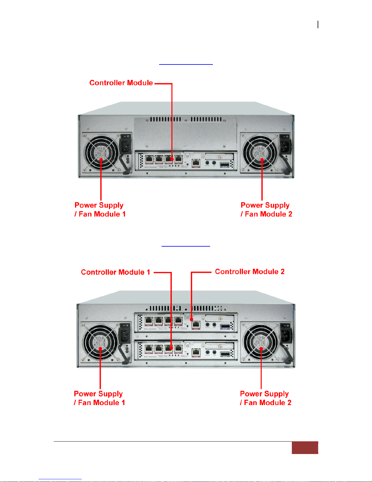
2.1.2 Rear View
Single Controller
Dual Controller

iSCSI GbE to SAS/SATA II RAID Subsystem
22
User Manual
1. Controller Module
The subsystem has one or two controller modules.
2. Power Supply Unit 1 ~ 2
Two power supplies (power supply 1 and power supply 2) are located at the rear of the
subsystem. Each PSFM has one Power Supply and one Fan. The PSFM 1 has Power#1,
Fan#1. The PSFM 2 has Power#2, Fan#2.
Turn on the power of these power supplies to power-on the subsystem. The “power”
LED at the front panel will turn green.
If a power supply fails to function or a power supply was not turned on, the “
”
Power fail LED will turn red and an alarm will sound.
2.2 Controller Module
The EPICa RAID system includes single/dual 3Gb SAS-to-SAS/SATA II RAID
Controller Module.
RAID Controller Module

iSCSI GbE to SAS/SATA II RAID Subsystem
User Manual
23
2.2.1 Controller Module Panel
1. Uninterrupted Power Supply (UPS) Port (APC Smart UPS only)
The subsystem may come with an optional UPS port allowing you to connect an APC
Smart UPS device. Connect the cable from the UPS device to the UPS port located at
the rear of the subsystem. This will automatically allow the subsystem to use the
functions and features of the UPS.
2. R-Link Port: Remote Link through RJ-45 Ethernet for remote management
The subsystem is equipped with one 10/100 Ethernet RJ45 LAN port for remote
configuration and monitoring. You use web browser to manage the RAID subsystem
through Ethernet.
3. LAN Ports (Gigabit)
The subsystem is equipped with four LAN data ports for iSCSI connection.
4. Controller Status LED
Green Controller status normal or in the booting.
Red Other than above status.
5. Master/Slave LED
Green Master controller.
Off Slave controller.
6. Cache Dirty LED
Orange Data on the cache waiting for flush to disks.
Off No data on the cache.

iSCSI GbE to SAS/SATA II RAID Subsystem
24
User Manual
7. BBM Status LED
Green BBM installed and powered
Off No BBM
8. BBM Status Button
When the system power is off, press the BBM status button, if the BBM LED is Green,
then the BBM still has power to keep data on the cache. If not, then the BBM power
is ran out and cannot keep the data on the cache anymore.
2.3 Power Supply / Fan Module (PSFM)
The RAID subsystem contains two 460W Power Supply / Fan Modules. All the
Power Supply / Fan Modules (PSFMs) are inserted into the rear of the chassis.

iSCSI GbE to SAS/SATA II RAID Subsystem
User Manual
25
2.3.1 PSFM Panel
The panel of the Power Supply/Fan Module con tains: the Power On/Off Switch, the
AC Inlet Plug, FAN fail Indicator, and a Power On/Fail Indicator sh owing the Power
Status LED, indicating ready or fail.
Each fan within a PSFM is powered independently of the power supply within the
same PSFM. So if the power supply of a PSFM fails, the fan associated with that
PSFM will continue to operate and cool the enclosure.
FAN Fail Indicator
If fan is failed, this LED will turn to RED and alarm will sound.
Power On/Fail Indicator
When the power cord connected from main power source is inserted to the AC
Power Inlet, the power status LED becomes RED. When the switch of the PSFM is
turned on, the LED will turn GREEN. When the Power On/Fail LED is GREEN, the
PSFM is functioning normally.
NOTE: Each PSFM has one Power Supply and one Fan. The PSFM 1
has Power#1 and Fan#1. The PSFM 2 has Power#2 and Fan#2. When
the Power Supply of a PSFM fails, the PSFM need not be removed
from the slot if replacement is not yet available. The fan will still
work and provide necessary airflow inside the enclosure.
NOTE: After replacing the Power Supply Fan Module and turning on
the Power On/Off Switch of the PSFM, the Power Supply will not
power on immediately. The Fans in the PSFM will spin-up u ntil the
RPM becomes stable. When Fan RPM is already stable, the RAID
controller will then power on the Power Supply. This process takes
more or less 30 seconds. This safety measure helps prevent possible
Power Supply overheating when the Fans cannot work.

iSCSI GbE to SAS/SATA II RAID Subsystem
26
User Manual
2.4 Checklist before Starting
Before starting, check or prepare the following items.
Check “Certification list” in Appendix A to confirm the hardware setting is fully
supported.
Read the latest release note before upgrading. Release note accompany with
release firmware.
A server with a NIC or iSCSI HBA.
CAT 5e, or CAT 6 network cables for management port and iSCSI data ports.
Recommend CAT 6 cables for best performance.
Prepare storage system configuration plan.
Management and iSCSI data ports network information. When using static IP,
please prepare static IP addresses, subnet mask, and default gateway.
Gigabit LAN switches. (recommended) Or Gigabit LAN switches with
VLAN/LCAP/Trunking. (optional)
CHAP security information, including CHAP username and secret. (optional)
Setup the hardware connection before powering on the server(s) and the iSCSI
RAID system.
In Addition, installing an iSNS server is recommended.
Host server is suggested to logon the target twice (both controller 1 and
controller 2), and then MPIO should be setup automatically.
NOTE: iSNS server is recommended for dual controller system.
For better data service availability, all the connections among host servers, GbE switches,
and the dual controllers are recommended as redundant as below.

iSCSI GbE to SAS/SATA II RAID Subsystem
User Manual
27

iSCSI GbE to SAS/SATA II RAID Subsystem
28
User Manual
Chapter 3 Getting Started with the Subsystem
3.1 Connecting the iSCSI RAID Subsystem to the Network
To connect the iSCSI unit to the network, insert the network cable that came with the
unit into the network port (LAN1) at the back of iSCSI unit. Insert the other end into a
Gigabit BASE-T Ethernet connection on your network hub or switch. You may connect
the other network ports if needed.
For remote management of iSCSI RAID subsystem, use another network cable to
connect the R-Link port to your network.
3.2 Powering On
1. Plug in the power cords into the AC Power Input Socket located at the rear of the
subsystem.
NOTE: The subsystem is equipped with redundant, full range
power supplies with PFC (power factor correction). The system will
automatically select voltage.
2. Turn on each Power On/Off Switch to power on the subsystem.
3. The Power LED on the front Panel will turn green.

iSCSI GbE to SAS/SATA II RAID Subsystem
User Manual
29
3.3 Disk Drive Installation
This section describes the physical locations of the hard drives supported by the
subsystem and give instructions on installing a hard drive. The subsystem supports
hot-swapping allowing you to install or replace a hard drive while the subsyst em is
running.
3.3.1 Installing a SAS Disk Drive in a Disk Tray
1. Unlock the Disk Trays using a flat-head screw driver by rotating the Lock Groove.
2. Press the Tray Open button and the Disk Tray handle will flip open.
3. Pull out an empty disk tray.
Tray
Open
B
utto
n

iSCSI GbE to SAS/SATA II RAID Subsystem
30
User Manual
4. Place the hard drive in the disk tray. Turn the disk tray upside down. Align the
four screw holes of the SAS disk drive in the four Hole A of the disk tray. To
secure the disk drive into the disk tray, tighten four screws on these holes of the
disk tray. Note in the picture below where the screws should be placed in the disk
tray holes.
NOTE: All the disk tray holes are labelled accordingly.
Tray Hole A

iSCSI GbE to SAS/SATA II RAID Subsystem
User Manual
31
5. Slide the tray into a slot.
6. Press the lever in until you hear the latch click into place. The HDD Fault LED will
turn green when the subsystem is powered on and HDD is good.
7. If necessary, lock the Disk Tray by turning the Lock Groove.

iSCSI GbE to SAS/SATA II RAID Subsystem
32
User Manual
3.3.2 Installing a SATA Disk Drive (Dual Controller Mode) in a Disk Tray
1. Remove an empty disk tray from the subsystem.
2. Prepare the dongle board and two screws.
3. Place the dongle board in the disk tray. Turn the tray upside down. Align the two
screw hole of the dongle board in the two Hole D of the disk tray. Tighten two
screws to secure the dongle board into the disk tray.
iSCSI GbE to SAS/SATA II RAID Subsystem
User Manual
33
NOTE: All the disk tray holes are labelled accordingly.
4. Place the SATA disk drive into the disk tray. Slide the disk drive towards the
dongle board.
Tray Hole D
iSCSI GbE to SAS/SATA II RAID Subsystem
34
User Manual
5. Turn the disk tray upside down. Align the four screw holes of the SATA disk drive
in the four Hole C of the disk tray. To secure the disk drive into the disk tray,
tighten four screws on these holes of the disk tray. Note in the picture below
where the screws should be placed in the disk tray holes.
NOTE: All the disk tray holes are labelled accordingly.
6. Insert the disk tray into the subsystem.
Tray Hole C
iSCSI GbE to SAS/SATA II RAID Subsystem
User Manual
35
3.4 iSCSI Introduction
iSCSI (Internet SCSI) is a protocol which encapsulates SCSI (Small Computer System
Interface) commands and data in TCP/IP packets for linking storage devices with
servers over common IP infrastructures. iSCSI provides high performance SANs over
standard IP networks like LAN, WAN or the Internet.
IP SANs are true SANs (Storage Area Networks) which allow few of servers to attach to
an infinite number of storage volumes by using iSCSI over TCP/IP networks. IP SANs
can scale the storage capacity with any type and brand of storage system. In addition,
using any type of network (Ethernet, Fast Ethernet, Gigabit Ethernet) and combining
operating systems (Microsoft Windows, Linux, Solaris, …etc.) within the SAN network.
IP-SANs also include mechanisms for security, data replication, multi-path and high
availability.
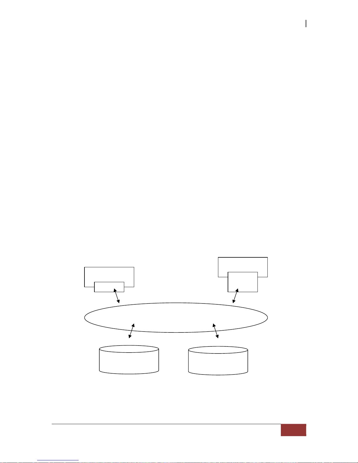
Storage protocol, such as iSCSI, has “two ends” in the connection. These ends are the
initiator and the target. In iSCSI we call them iSCSI initiator and iSCSI target. The
iSCSI initiator requests or initiates any iSCSI communication. It requests all SCSI
operations like read or write. An initiator is usually located on the host/server side
(either an iSCSI HBA or iSCSI SW initiator).
The iSCSI target is the storage device itself or an appliance which controls an d serves
volumes or virtual volumes. The target is the device which performs SCSI comman ds
or bridges it to an attached storage device. iSCSI targets can be disks, tapes, RAID
arrays, tape libraries, and etc.
iSCSI device 1
(target)
Host 1
(initiator)
NI
C
IP SAN
Host 2
(initiator)
iSCSI
HBA
iSCSI device 2
(target)

iSCSI GbE to SAS/SATA II RAID Subsystem
36
User Manual
The host side needs an iSCSI initiator. The initiator is a driv er which handles the SCSI
traffic over iSCSI. The initiator can be software or hardware (HBA). Please refer to the
certification list of iSCSI HBA(s) in Appendix A. OS native initiators or other software
initiators use the standard TCP/IP stack and Ethernet hardw are, while iSCSI HBA(s)
use their own iSCSI and TCP/IP stacks on board.
Hardware iSCSI HBA(s) would provide its initiator tool. Please refer to the vendors’
HBA user manual. Microsoft, Linux and Mac provide softw are iSCSI initiator driver.
Below are the available links:
1. Link to download the Microsoft iSCSI software initiator:
http://www.microsoft.com/downloads/details.aspx?FamilyID=12cb3c1a-15d64585-b385-befd1319f825&DisplayLang=en
Please refer to Appendix D for Microsoft iSCSI initiator installation procedur e.
2. Linux iSCSI initiator is also av ailab le. For diff eren t kernels, there are dif feren t iSCSI
drivers. If you need the latest Linux iSCSI initiator, please visit Open-iSC SI project
for most update information. Linux-iSCSI (sfnet) and Open-iSCSI projects merged
in April 11, 2005.
Open-iSCSI website: http://www.open-iscsi.org/
Open-iSCSI README: http://www.open-iscsi.org/docs/README
Features: http://www.open-iscsi.org/cgi-bin/wiki.pl/Roadmap
Support Kernels: http://www.open-iscsi.org/cgi-bin/wiki.pl/Supported_Kernels
Google groups: http://groups.google.com/group/open-iscsi/threads?gvc=2
http://groups.google.com/group/open-iscsi/topics
Open-iSCSI Wiki: http://www.open-iscsi.org/cgi-bin/wiki.pl
3. ATTO iSCSI initiator is available for Mac.
Website: http://www.attotech.com/xtend.html
4. Solaris iSCSI Initiator
Version: Solaris 10 u6 (10/08)

iSCSI GbE to SAS/SATA II RAID Subsystem
User Manual
37
Chapter 4 Quick Setup
4.1 Management Interfaces
There are three management methods to manage the iSCSI RAID subsystem described
as follows:
4.1.1 Serial Console Port
Use NULL modem cable to connect console port.
The console settings are on the following:
Baud rate: 115200, 8 bits, 1 stop bit, and no parity.
Terminal type: vt100
Login name: admin
Default password: 00000000
4.1.2 Remote Control – Secure Shell
SSH (secure shell) is required for remote login. The SSH client software is available at
the following web site:
SSHWinClient WWW: http://www.ssh.com/
Putty WWW: http://www.chiark.greenend.org.uk/
Host name: 192.168.10.50 (Please check your DHCP address for this field.)
Login name: admin
Default password: 00000000
NOTE: This iSCSI RAID Series only support SSH for remote
control. For using SSH, the IP address and the password is
required for login.
iSCSI GbE to SAS/SATA II RAID Subsystem
38
User Manual
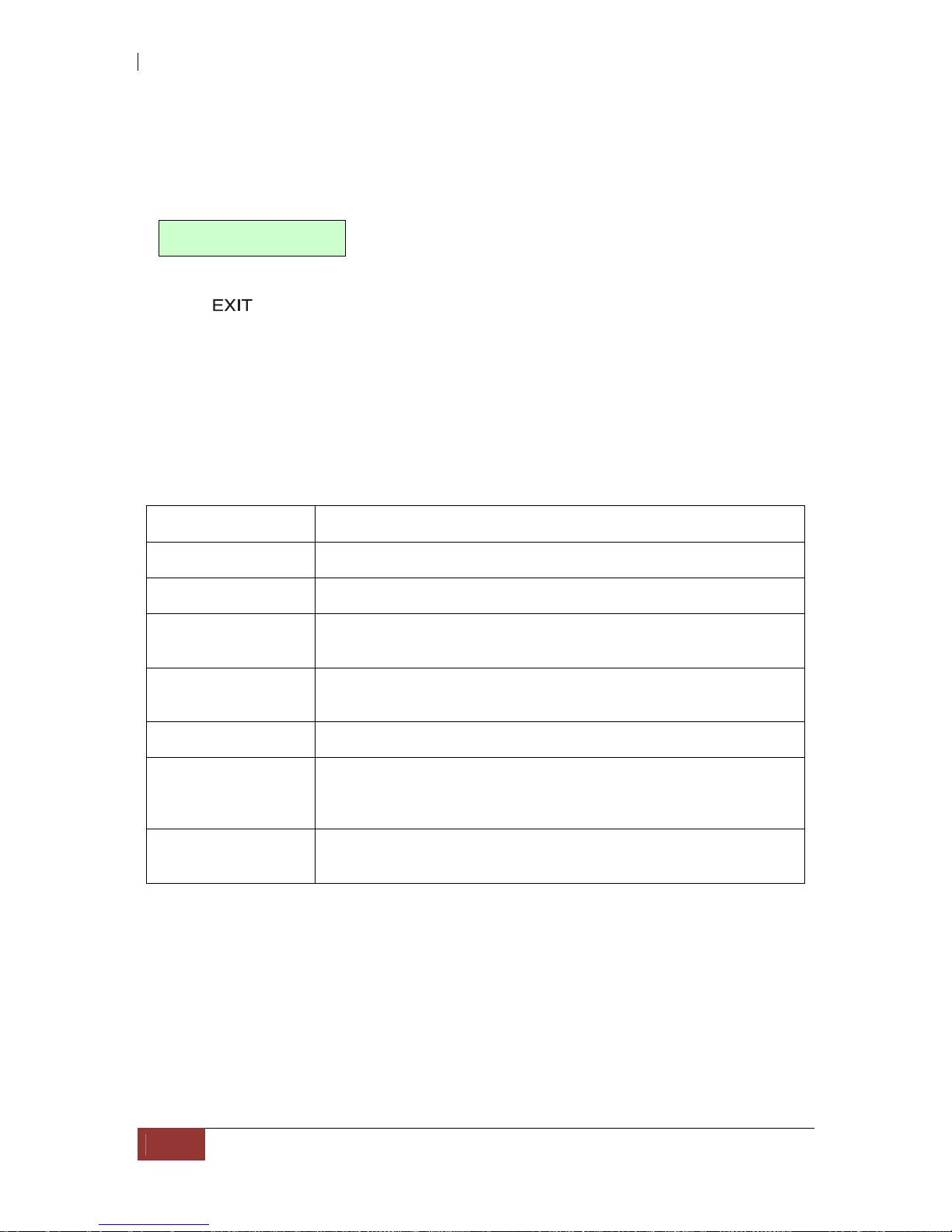
4.1.3 LCD Control Module (LCM)
After booting up the system, the following screen shows management port IP and
model name:
192.168.10.50
iSCSI-Model
Press “
”, the LCM functions “Alarm Mute”, “Reset/Shutdown”, “Quick
Install”, “View IP Setting”, “Change IP Config” and “Reset to Default” will
rotate by pressing (up) and (down).
When there is WARNING or ERROR level of event happening, the LCM also shows the
event log to give users event information from front panel.
The following table is the function description of LCM menus.
System Info Displays System information.
Alarm Mute Mute alarm when error occurs.
Reset/Shutdown Reset or shutdown controller.
Quick Install Quick three steps to create a volume. Please refer to next
chapter for operation in web UI.
Volume Wizard Smart steps to create a volume. Please refer to next chapter
for operation in web UI.
View IP Setting Display current IP address, subnet mask, and gateway.
Change IP Config Set IP address, subnet mask, and gateway. There are 2
selections, DHCP (Get IP address from DHCP server) or set
static IP.
Reset to Default Reset to default sets password to default: 00000000, and set
IP address to default as DHCP setting.

iSCSI GbE to SAS/SATA II RAID Subsystem
User Manual
39
The following is LCM menu hierarchy.
proIPS
[System Info.]
[Firmware Version
x.x.x]
[RAM Size
xxx MB]
[Alarm Mute] [Yes No]
[Reset/Shutdown]
[Reset]
[Yes
No]
[Shutdown]
[Yes
No]
[Quick Install]
RAID 0
RAID 1
RAID 3
RAID 5
RAID 6
RAID 0+1
xxx GB
[Apply
The
Config]
[Yes
No]
[Volume Wizard]
[Local]
RAID 0
RAID 1
RAID 3
RAID 5
RAID 6
RAID 0+1
[Use
default
algorithm]
[Volume
Size]
xxx GB
[Apply
The
Config]
[Yes
No]
[JBOD x]
RAID 0
RAID 1
RAID 3
RAID 5
RAID 6
RAID 0+1
[new x
disk]
xxx BG
Adjust
Volume
Size
[Apply
The
Config]
[Yes
No]
[View IP Setting]
[IP Config]
[Static IP]
[IP Address]
[192.168.010.050]
[IP Subnet Mask]
[255.255.255.0]
[IP Gateway]
[192.168.010.254]
[Change IP
Config]
[DHCP]
[Yes
No]
[Static IP]
[IP
Address]
Adjust IP
address
[IP Subnet
Mask]
Adjust
Submask
IP
[IP
Gateway]
Adjust
Gateway
IP
[Apply IP
Setting]
[Yes
No]
[Reset to Default] [Yes No]

iSCSI GbE to SAS/SATA II RAID Subsystem
40
User Manual
CAUTION! Before power off, it is better to execute “Shutdown” to
flush the data from cache to physical disks.
4.1.4 Web GUI
The iSCSI RAID subsystem supports graphical user interface (GUI) to operate the
system. Be sure to connect the LAN cable. The default IP setting is DHCP; open the
browser and enter:
http://192.168.10.50 (Please check the DHCP address first on LCM)
Click any function at the first time; it will pop up a dialog wind ow for authentication.
User name: admin
Default password: 00000000
After login, you can choose the function blocks on the left side of window to do
configuration.
iSCSI GbE to SAS/SATA II RAID Subsystem
User Manual
41
There are seven indicators at the top-right corner.
RAID light:
Green RAID works well.
Red RAID fails.
Temperature light:
Green Temperature is normal.
Red Temperature is abnormal.
Voltage light:
Green voltage is normal.
Red voltage is abnormal.
UPS light:
Green UPS works well.
Red UPS fails.
Fan light:
Green Fan works well.
Red Fan fails.
Power light:
Green Power works well.
Red Power fails.
Dual controller light:
Green Both controller1 and controller2 are
present and well.
Orange The system is degraded and there is
only 1 controller alive and well.
Return to home page.
Logout the management web UI.
Mute alarm beeper.

iSCSI GbE to SAS/SATA II RAID Subsystem
42
User Manual
4.2 How to Use the System Quickly
4.2.1 Quick Installation
Please make sure that there are some free drives installed in this system. SAS drivers
are recommended. Please check the hard drive details in “/ Volume configuration /
Physical disk”.
Step 1: Click “Quick installation” menu item. Follow the steps to set up system
name and date/time.

iSCSI GbE to SAS/SATA II RAID Subsystem
User Manual
43
Step2: Confirm the management port IP address and DNS, and then click “Next”.
Step 3: Set up the data port IP and click “Next”.

iSCSI GbE to SAS/SATA II RAID Subsystem
44
User Manual
Step 4: Set up the RAID level and volume size and click “Next”.
Step 5: Check all items, and click “Finish”.
Step 6: Done.

iSCSI GbE to SAS/SATA II RAID Subsystem
User Manual
45
4.2.2 Volume Creation Wizard
“Volume create wizard” has a smarter policy. When the system is inserted with some
HDDs. “Volume create wizard” lists all possibilities and sizes in different RAID levels,
it will use all available HDDs for RAID level depends on which user chooses. When
system has different sizes of HDDs, e.g., 8*200G and 8*80G, it lists all possibilities and
combination in different RAID level and different sizes. After user chooses RAID level,
user may find that some HDDs are available (free status). It gives user:
1. Biggest capacity of RAID level for user to choose and,
2. The fewest disk number for RAID level / volume size.
E.g., user chooses RAID 5 and the controller has 12*200G + 4*80G HDDs inserted. If
we use all 16 HDDs for a RAID 5, and then the maximum size of volume is 1200G
(80G*15). By the wizard, we do smarter check and find out the most efficient way of
using HDDs. The wizard only uses 200G HDDs (Volume size is 200G*11=2200G), the
volume size is bigger and fully uses HDD capacity.
Step 1: Select “Volume create wizard” and then choose the RAID level. After the
RAID level is chosen, click “Next”.

iSCSI GbE to SAS/SATA II RAID Subsystem
46
User Manual
Step 2: Please select the combination of the RG capacity, or “Use default algorithm”
for maximum RG capacity. After RG size is chosen, click “Next”.
Step 3: Decide VD size. User can enter a number less or equal to the default number.
Then click “Next”.
Step 4: Confirmation page. Click “Finish” if all setups are correct. Then a VD will be
created.
Step 5: Done. The system is available now.
NOTE: A virtual disk of RAID 0 is created and is named by system
itself.

iSCSI GbE to SAS/SATA II RAID Subsystem
User Manual
47
Chapter 5 Configuration
5.1 Web GUI Management Interface Hierarchy
The below table is the hierarchy of the management GUI.
System configuration
System setting
System name / Date and time / System indication
Network settin
g
MAC address / Address / DNS / Port
Login setting
Login configuration / Admin password / User
password
Mail setting
Mail
Notification
setting
SNMP / Messenger / System log server / Event log
filter
iSCSI configuration
NIC
Show information for:(Controller 1/ Controller 2)
Aggregation / IP settings for iSCSI ports / Become
default gateway / Enable jumbo frame / Ping host
Entity property
Entity name / iSNS IP
Node
Show information for:(Controller 1/ Controller 2)
Authenticate / Change portal / Rename alias/ User
Session
Show information for:(Controller 1/ Controller 2)
List connection / Delete
CHAP account
Create / Modify user information / Delete
Volume configuration
Physical disk
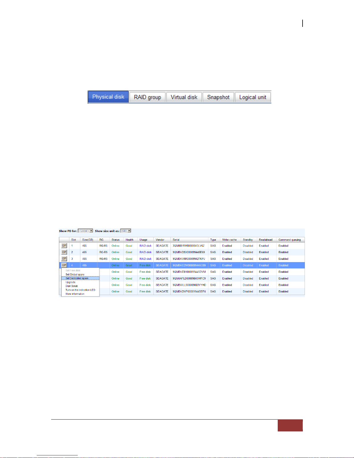
Set Free disk / Set Global spare / Set Dedicated
spare / Upgrade / Disk Scrub / Turn on/off the
indication LED / More information
RAID group
Create / Migrate / Activate / Deactivate / Parity
check / Delete / Set preferred owner /Set disk
property / More information
Virtual disk
Create / Extend / Parity check / Delete / Set
property / Attach LUN / Detach LUN / List LUN /
Set clone / Clear clone / Start clone / Stop clone /
Schedule clone / Set snapshot space / Cleanup
snapshot / Take snapshot / Auto snapshot / List
snapshot / More information
Snapshot
Set snapshot space / Auto snapshot / Take
snapshot / Export / Rollback / Delete/ Cleanup
snapshot
Logical unit
Attach / Detach/ Session
Enclosure management
Hardware
monitor
Controller 1 / BPL / Controller 2 / Auto shutdown
UPS
UPS Type / Shutdown battery level / Shutdown
delay / Shutdown UPS
SES
Enable / Disable
S.M.A.R.T.
S.M.A.R.T. information (Only for SATA hard
drives)

iSCSI GbE to SAS/SATA II RAID Subsystem
48
User Manual
Maintenance
System
information
System information
Event log
Download / Mute / Clear
Upgrade
Browse the firmware to upgrade
Firmware sync
hronization
Synchronize the slave controller’s firmware version
with the master’s
Reset to factor
y default
Sure to reset to factory default?
Import and
export
Import/Export / Import file
Reboot and shu
tdown
Reboot / Shutdown
Quick installation Step 1 / Step 2 / Step 3 / Step 4 / Confirm
Volume creation wizard Step 1 / Step 2 / Step 3 / Confirm

iSCSI GbE to SAS/SATA II RAID Subsystem
User Manual
49
5.2 System Configuration
“System configuration” is designed for setting up the “System setting”,
“Network setting”, “Login setting”, “Mail setting”, and “Notification setti ng”.
5.2.1 System Setting
“System setting” can be used to set system name and date. Default “System
name” is composed of model name and serial number of this system.
Check “Change date and time” to set up the current date, time, and time zone before
using or synchronize time from NTP (Network Time Protocol) server. Click “Confirm” in
System indication to turn on the system indication LED. Click again to turn off.
iSCSI GbE to SAS/SATA II RAID Subsystem
50
User Manual
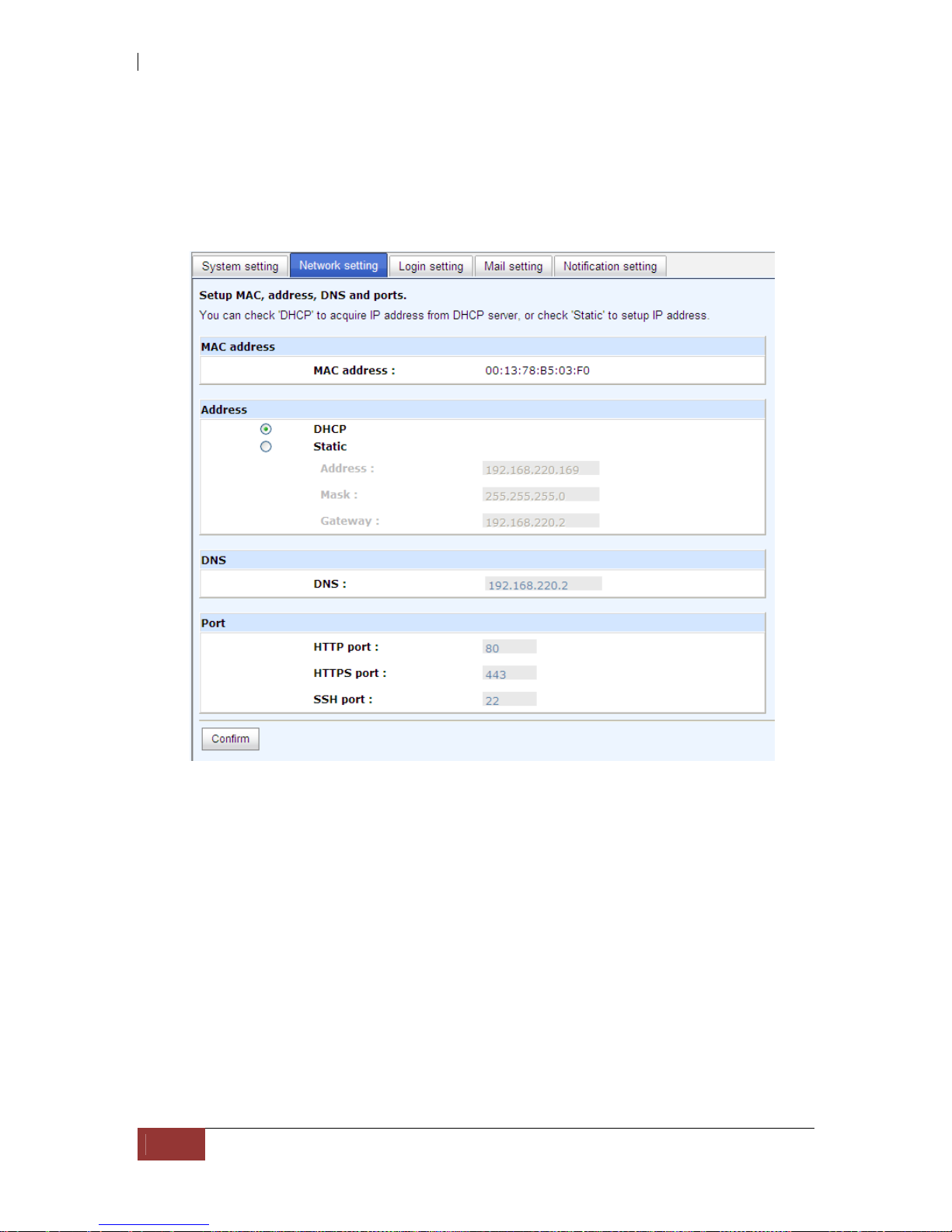
5.2.2 Network Setting
“Network setting” is for changing IP address for remote administration usage. There
are 2 options, DHCP (Get IP address from DHCP server) and static IP. The default setting
is DHCP. User can change the HTTP, HTTPS, and SSH port number when the default port
number is not allowed on host/server.
iSCSI GbE to SAS/SATA II RAID Subsystem
User Manual
51
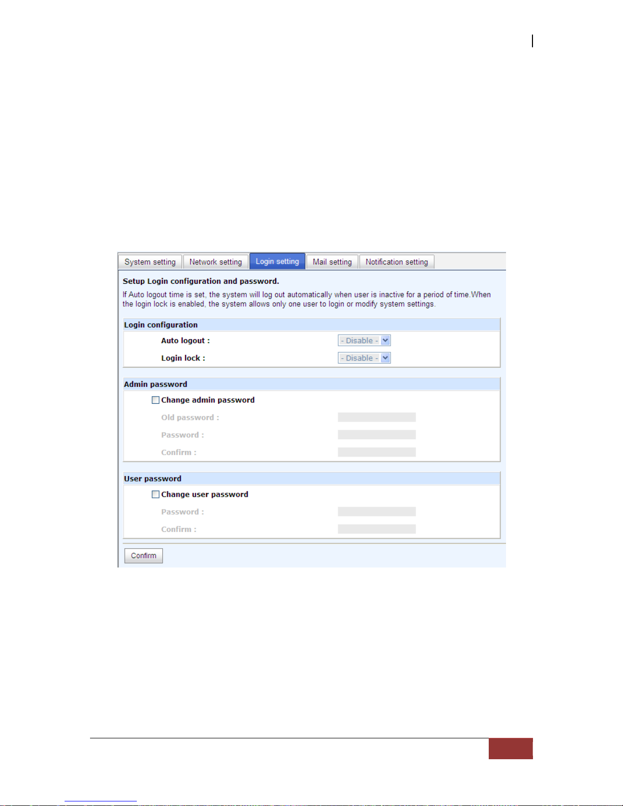
5.2.3 Login Setting
“Login setting” can set single admin, auto logout time and Admin/User password.
The single admin can prevent multiple users access the same controller at the same
time.
1. Au to logout: The options are (1) Disable; (2) 5 minutes; (3) 30 minutes; (4)
1 hour. The system will log out automatically when user is inactive for a period
of time.
2. Login lock: Disable/Enable. Wh en th e login lo ck is en abled, th e syst em allow s
only one user to login or modify system settings.
Check “Change admin password” or “Change user password” to change admin or
user password. The maximum length of password is 12 characters.
iSCSI GbE to SAS/SATA II RAID Subsystem
52
User Manual
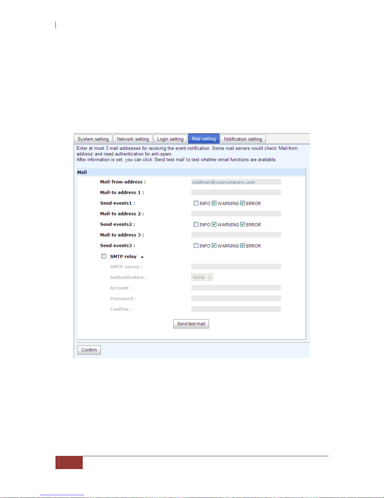
5.2.4 Mail Setting
“Mail setting” can accept at most 3 mail-to address entries for receiving the event
notification. Some mail servers would check “Mail-from address” and need
authentication for anti-spam. Please fill the necessary fields and click “Send test mail”
to test whether email functions are available or working. User can also select which
levels of event logs are needed to be sent via Mail. Default setting only enables ERROR
and WARNING event logs. Please also make sure the DNS server IP is well-setup so the
event notification mails can be sent successfully.

iSCSI GbE to SAS/SATA II RAID Subsystem
User Manual
53
5.2.5 Notification Setting
“Notification setting” can be used to set up SNMP trap for alerting via SNMP, pop-up
message via Windows messenger (not MSN), alert via syslog protocol, and event log
filter.
“SNMP” allows up to 3 SNMP trap addresses. Default community name is set as
“public”. User can choose the event log levels and default setting only enables INFO
event log in SNMP. There are many SNMP tools. The following web sites are for your
reference:
SNMPc: http://www.snmpc.com/
Net-SNMP: http://net-snmp.sourceforge.net/
Using “Messenger”, user must enable the service “Messenger” in Windows (Start
Control Panel Administrative Tools Services Messenger), and then event logs
can be received. It allows up to 3 messenger addresses. User can choose the event log
levels and default setting enables the WARNING and ERROR event logs.
Using “System log server”, user can choose the facility and the event log level. The
default port of syslog is 514. The default setting enables event level: INFO, WARNING
and ERROR event logs.

iSCSI GbE to SAS/SATA II RAID Subsystem
54
User Manual
Configuration
The following configuration is a sample for target and log server setting:
Target side
1. Go to \System configuration\Notification setting\System log server.
2. Fill the fields
3. Server IP/hostname: enter the IP address or hostname of system log server.
4. UDP Port: enter the UDP port number on which system log server is listening to.
The default port number is 514.
5. Facility: select the facility for event log.
6. Event level: Select the event log options.
7. Click “Confirm” button.
Server side (Linux – RHEL4)
The following steps are used to log RAID subsystem messages to a disk file. In
the following, all messages are setup with facility “Local1” and event level
“WARNING” or higher are logged to /var/log/raid.log.
1. Flush firewall
2. Add the following line to /etc/syslog.conf
Local1.warn /var/log/raid.log
3. Send a HUP signal to syslogd process, this lets syslogd perform a re-initialization.
All open files are closed, the configuration file (default is /etc/syslog.conf) will be
reread and the syslog(3) facility is started again.
4. Activate the system log daemon and restart
Note: sysklogd has a parameter "-r" , which will enable sysklogd to receive
message from the network using the internet domain socket with the syslog
service, this option is introduced in version 1.3 of sysklogd package.
5. Check the syslog port number,
e.g. , 10514
6. Change controller’s system log server port number as above
Then, syslogd will direct the selected event log messages to /var/log/raid.log
when syslogd receive the messages from RAID subsystem.
For more detail features, please check the syslogd and syslog.conf manpage
(e.g.,man syslogd).
Server side (Windows 2003)
Windows doesn’t provide system log server, user needs to find or purchase a
client from third party, below URL provide evaluation version, you may use it for
test first. http://www.winsyslog.com/en/
1. Install winsyslog.exe
2. Open "Interactives Syslog Server"
3. Check the syslog port number, e.g., 10514
4. Change controller’s system log server port number as above
5. Start logging on "Interactives Syslog Server"
There are some syslog server tools. The following web sites are for your reference:
WinSyslog: http://www.winsyslog.com/
Kiwi Syslog Daemon: http://www.kiwisyslog.com/
Most UNIX systems have built-in syslog daemon.
“Event log filter” setting can enable event level on “Pop up events” and “LCM”.
iSCSI GbE to SAS/SATA II RAID Subsystem
User Manual
55
5.3 iSCSI Configuration
“iSCSI configuration” is designed for setting up the “Entity Property”, “NIC”,
“Node”, “Session”, and “CHAP account”.
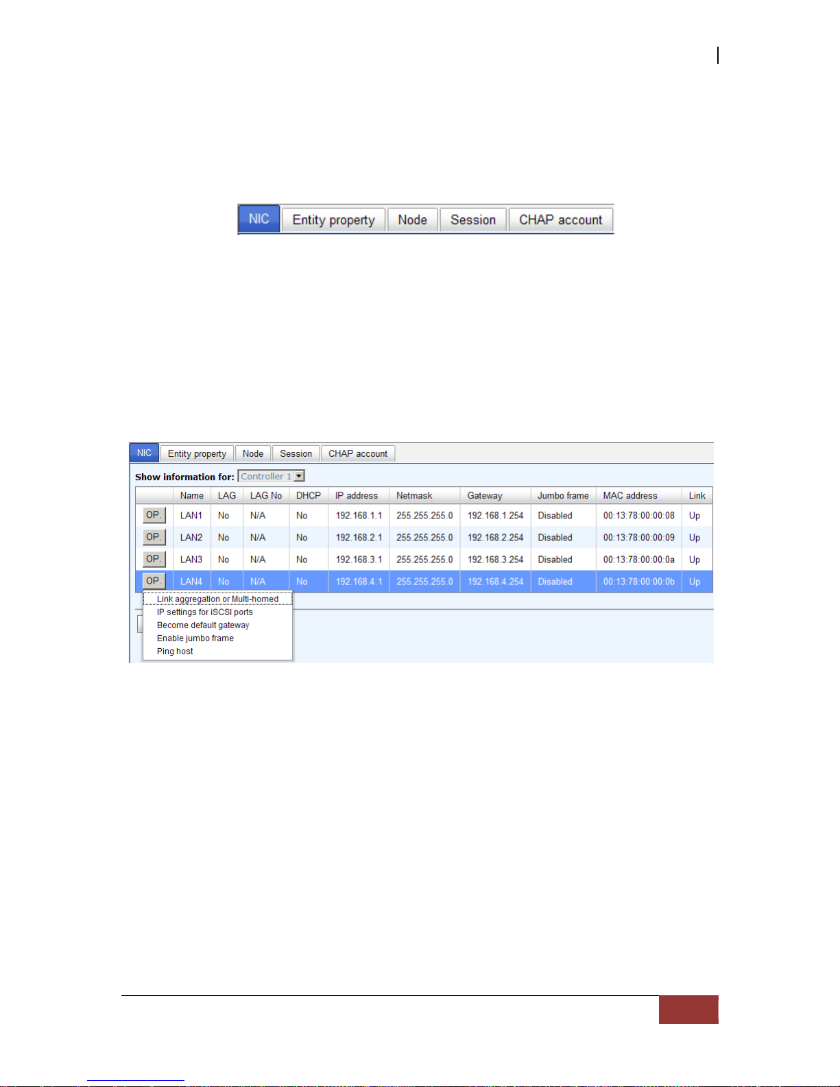
5.3.1 NIC
“NIC” function is used to change the IP addresses of iSCSI data ports. The iSCSI RAID
subsystem has four gigabit LAN ports to transmit data. Each of them must be assigned
to one IP address in multi-homed mode unless the link aggregation or trunking mode
has been selected. When there are multiple data ports setting up in link aggregation or
trunking mode, all the data ports share single address.
There are four iSCSI data ports on each controller. Four data ports are set with static IP.
iSCSI GbE to SAS/SATA II RAID Subsystem
56
User Manual
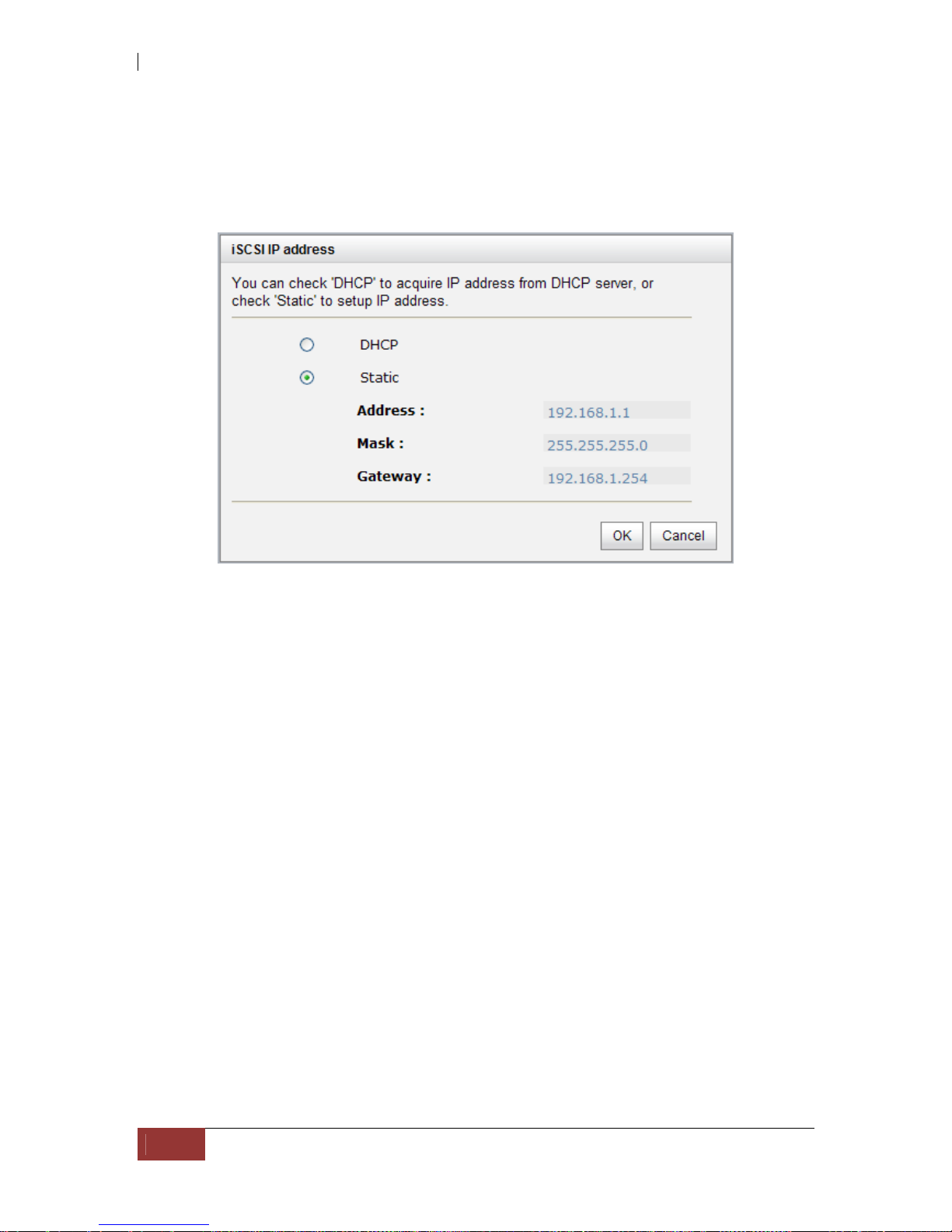
IP settings:
User can change IP address by moving the mouse to the gray button of LAN port, click
“IP settings for iSCSI ports”. There are 2 selections, DHCP (Get IP address from
DHCP server) or static IP.
Default gateway:
Default gateway can be changed by moving the mouse to the gray button of LAN port,
click “Become default gateway”. There is only one default gateway.
MTU / Jumbo frame:
MTU (Maximum Transmission Unit) size can be enabled by moving mouse to the gray
button of LAN port, click “Enable jumbo frame”.
WARNING! The MTU size of network switch and HBA on host must
be enabled. Otherwise, the LAN connection will not work properly.
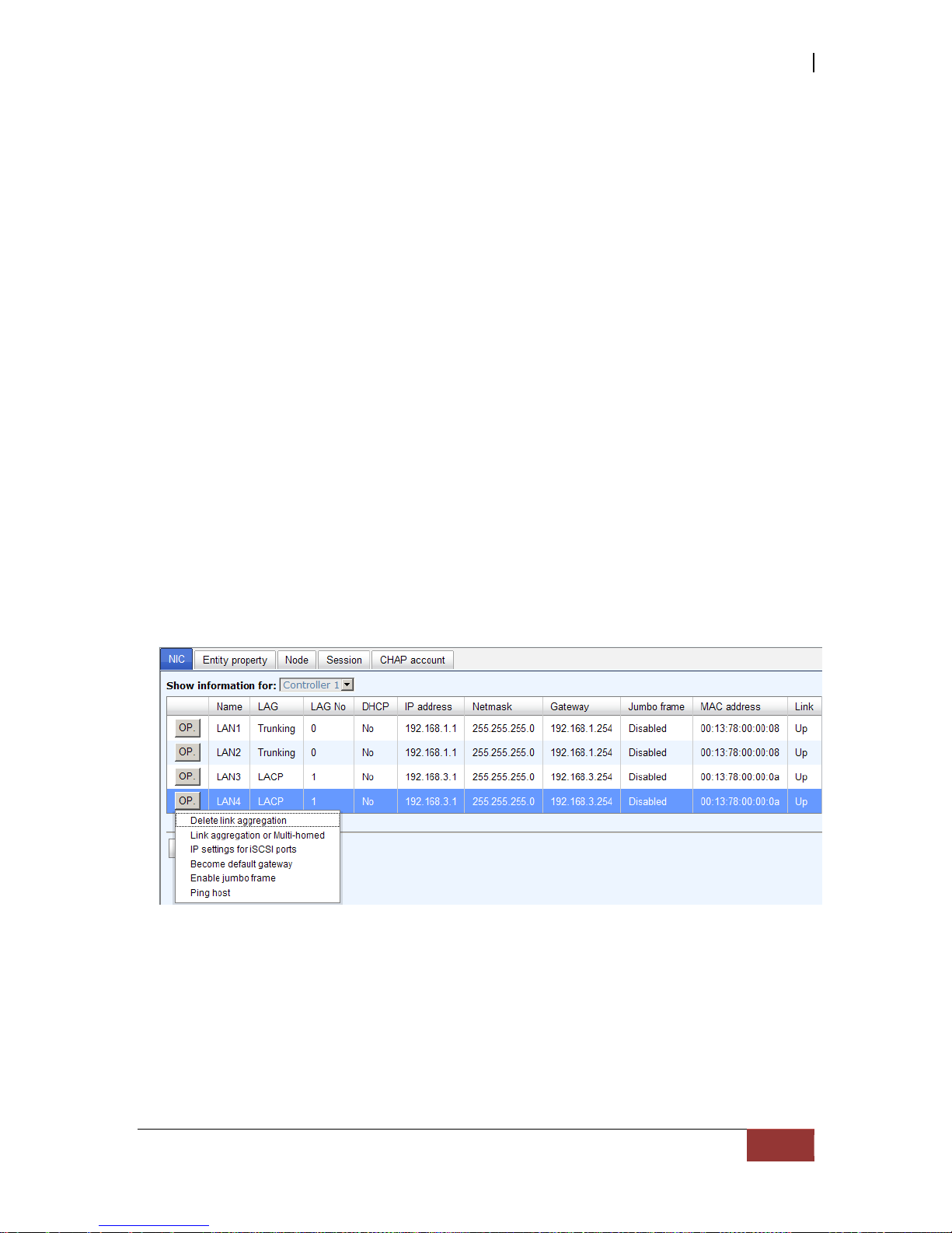
Multi-homed / Trunking / LACP:
The following is the description of multi-homed/trunk in g/LACP.
1. Multi-homed: Default mode. Each of iSCSI data port is connected by itself and is
not set to link aggregation and trunking. Selecting this mode can also remove the
setting of Trunking/LACP at the same time.
iSCSI GbE to SAS/SATA II RAID Subsystem
User Manual
57
2. Trunking: defines the use of multiple iSCSI data ports in parallel to increase the
link speed beyond the limits of any single port.
3. LACP: The Link Aggregation Control Protocol (LACP) is part of IEEE specification
802.3ad that allows bundling several physical ports together to form a single logical
channel. LACP allows a network switch to negotiate an automatic bundle by sending
LACP packets to the peer. The advantages of LACP are: (1) increase in bandwidth,
and (2) failover when link status fails on a port.
Trunking/LACP setting can be changed by clicking the button “Aggregation”.
There are 4 iSCSI data ports. Select at least two NICs for link aggregation.
For example, LAN1 and LAN2 are set to Trunking mode. LAN3 and LAN4 are set to
LACP mode. To remove Trunking/LACP setting, mouse move to the gray button of LAN
port, click “Delete link aggregation”. Then it will pop up a message to confirm.

iSCSI GbE to SAS/SATA II RAID Subsystem
58
User Manual
Ping host:
User can ping the corresponding host data port from the target, click “Ping host”.
A user can ping host from the target to make sure the data port connection is well.

iSCSI GbE to SAS/SATA II RAID Subsystem
User Manual
59
5.3.2 Entity Property
“Entity property” can view the entity name of the system, and setup “iSNS IP” for
iSNS (Internet Storage Name Service). iSNS protocol allows automated discovery,
management and configuration of iSCSI devices on a TCP/IP network. Using iSNS, it
needs to install an iSNS server in SAN. Add an iSNS server IP address into iSNS server
lists in order that iSCSI initiator service can send queries. The entity name can be
changed.

iSCSI GbE to SAS/SATA II RAID Subsystem
60
User Manual
5.3.3 Node
“Node” can be used to view the target name for iSCSI initiator. There are 32 default
nodes created for each controller.
CHAP:
CHAP is the abbreviation of Challenge Handshake Authorization Protocol. CHAP is a
strong authentication method used in point-to-point for user login. It’s a type of
authentication in which the authentication server sends the client a key to be used for
encrypting the username and password. CHAP enables the username and password to
transmitting in an encrypted form for protection.
To use CHAP authentication, please follow these steps:
1. Select one of 32 default nodes from one controller.
2. Check the gray button of “OP.” column, click “Authenticate”.
3. Select “CHAP”.

iSCSI GbE to SAS/SATA II RAID Subsystem
User Manual
61
4. Click “OK”.
5. Go to “/ iSCSI configuration / CHAP account” page to create CHAP account.
Please refer to next section for more detail.
6. Check the gray button of “OP.” column , click “User”.
7. Select CHAP user(s) which will be used. It’s a multi opt ion; it can be one or more. If
choosing none, CHAP cannot work.
8. Click “OK”.
9. In “Authenticate” of “OP” page, select “None” to disable CHAP.

iSCSI GbE to SAS/SATA II RAID Subsystem
62
User Manual
Change portal:
Users can change the portals belonging to the device node of each controller.
1. Check the gray button of “OP.” column next to one device node.
2. Select “Change portal”.
3. Choose the portals for the controller.
4. Click “OK” to confirm.
Rename alias:
User can create an alias to one device node.
1. Check the gray button of “OP.” column next to one device node.
2. Select “Rename alias”.
3. Create an alias for that device node.
4. Click “OK” to confirm.
5. An alias appears at the end of that device node.
NOTE: After setting CHAP, the initiator in host/server should be
set the same CHAP account. Otherwise, user cannot login.

iSCSI GbE to SAS/SATA II RAID Subsystem
User Manual
63
5.3.4 Session
“Session” can display iSCSI session and connection information, including the
following items:
1. TSIH (target session identifying handle)
2. Host (Initiator Name)
3. Controller (Target Name)
4. InitialR2T(Initial Ready to Transfer)
5. Immed. data(Immediate data)
6. MaxDataOutR2T(Maximum Data Outstanding Ready to Transfer)
7. MaxDataBurstLen(Maximum Data Burst Length)
8. DataSeginOrder(Data Sequence in Order)
9. DataPDUInOrder(Data PDU in Order)
10. Detail of Authentication status and Source IP: port number.
Move the mouse pointer to the gray button of session number, click “List
connection”. It will list all connection(s) of the session.
iSCSI GbE to SAS/SATA II RAID Subsystem
64
User Manual
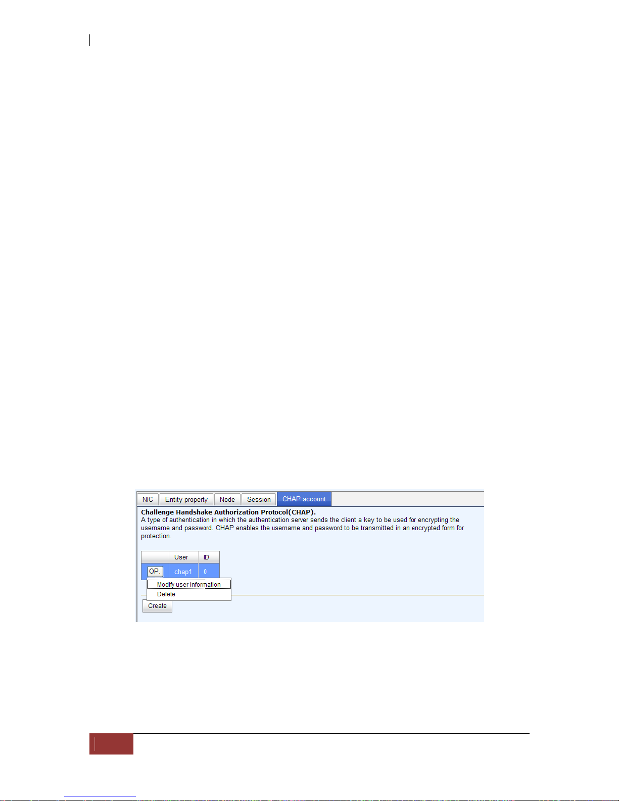
5.3.5 CHAP Account
“CHAP account” is used to manage CHAP accounts for authentication. This iSCSI
RAID subsystem allows creation of many CHAP accounts.
To setup CHAP account, please follow these steps:
1. Click “Create”.
2. Enter “User”, “Secret”, and “Confirm” secret again. “Node” can be selected
here or later. If selecting none, it can be enabled later in “/ iSCSI configuration /
Node / User”.
3. Click “OK”.
4. Click “Delete” to delete CHAP account.
iSCSI GbE to SAS/SATA II RAID Subsystem
User Manual
65
5.4 Volume Configuration
“Volume configuration” is designed for setting up the volume configuration which
includes “Physical disk”, “RAID group”, “Virtual disk”, “Snapshot”, and
“Logical unit”.
5.4.1 Physical Disk
“Physical disk” can be used to view the status of hard drives in the system. The
following are operational tips:
1. Check the gray button next to the number of slot, it will show the functions which
can be executed.
2. Active function can be selected, and inactive functions show up in gray color and
cannot be selected.
For example, set PD slot number 4 to dedicated spare disk.
Step 1: Check to the gray button of PD 4, select “Set Dedicated spare”, it will link to
next page.
Step 2: Maybe there are some existing RGs which can be assigned dedicate spare
disk. Select which RG will be assigned, then click “Submit”.
Step 3: Done. View “Physical disk” page.
iSCSI GbE to SAS/SATA II RAID Subsystem
66
User Manual
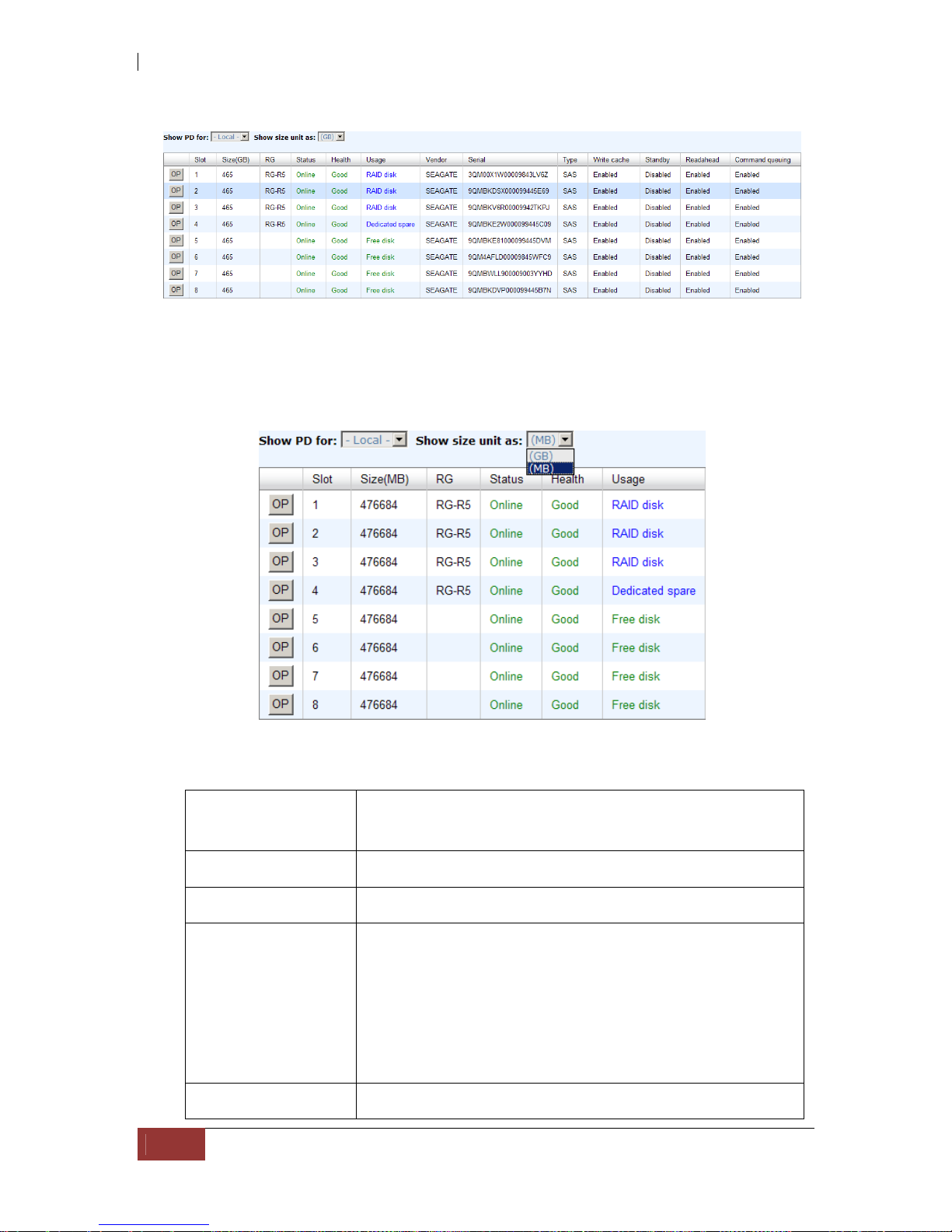
Physical Disk:
Physical disks in slot 1, 2, 3 are created for a RG named “RG-R5”. Slot 4 is set as
dedicated spare disk of the RG named “RG-R5”. The others are free disks.)
Step 4: The unit of size can be changed from (GB) to (MB). It will display the capacity of
hard drive in MB.
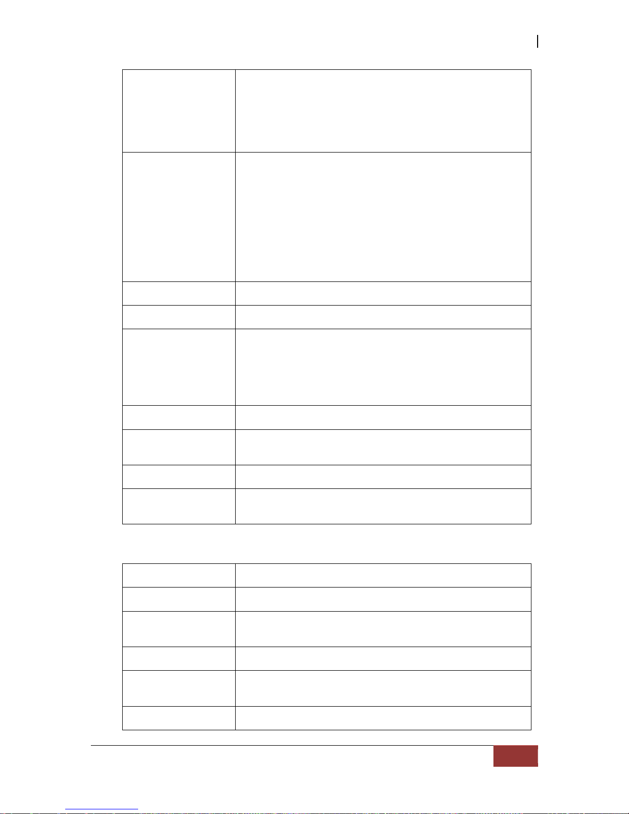
PD column description:
Slot
The position of hard drives. The button next to the
number of slot shows the functions which can be
executed.
Size (GB) Capacity of hard drive.
RG Name Related RAID group name.
Status The status of hard drive:
“Online” the hard drive is online.
“Rebuilding” the hard drive is being rebuilt.
“Transition” the hard drive is being migrated or
is replaced by another disk when rebuilding occurs.
“Scrubbing” the hard drive is being scrubbed.
Health The health of hard drive.
iSCSI GbE to SAS/SATA II RAID Subsystem
User Manual
67
“Good” the hard drive is good.
“Failed” the hard drive is failed.
“Error Alert” S.M.A.R.T. error alert.
“Read Errors” the hard drive has unrecoverable read
errors.
Usage The usage of hard drive:
“RAID disk” This hard drive has been set to
a RAID group.
“Free disk” This hard drive is free for use.
“Dedicated spare” This hard drive has been set
as dedicated spare of a RG.
“Global spare” This hard drive has been set as
global spare of all RGs.
Vendor Hard drive vendor.
Serial Hard drive serial number.
Type Hard drive type.
“SATA” SATA disk.
“SATA2” SATA II disk.
“SAS” SAS disk.
Write cache Hard drive write cache is enabled or disabled.
Standby HDD auto spindown function to save power. The default
value is disabled.
Readahead Readahead function of HDD. Default value is enabled
Command
Queuing
Command Queue function of HDD. Default value is
enabled.
PD operations description:
Set Free disk Make the selected hard drive to be free for use.
Set Global spare Set the selected hard drive to global spare of all RGs.
Set Dedicated
spares
Set hard drive to dedicated spare of selected RGs.
Disk Scrub Scrub the hard drive.
Turn on/off the
indication LED
Turn on the indication LED of the hard drive. Click again
to turn off.
More information Show hard drive detail information.

iSCSI GbE to SAS/SATA II RAID Subsystem
68
User Manual
5.4.2 RAID Group
“RAID group” can view the status of each RAID group, create, and modify RAID groups. The
following is an example to create a RG.
Step 1: Click “Create”, enter “Name”, choose “RAID level”, click “Select PD” to
select PD, assign the RG’s “Preferred owner”. Then click “OK”. The “Write Cache”
option is to enable or disable the hard drives’ write cache option. The “Standby” option
is to enable or disable the hard drives’ auto spindown function, when this option is
enabled and hard drives have no access after certain period of time, the hard drives
automatically spin down. The “Readahead” option is to enable or disable the read
ahead function. The “Command queuing” option is to enable or disable the hard
drives’ command queue function.
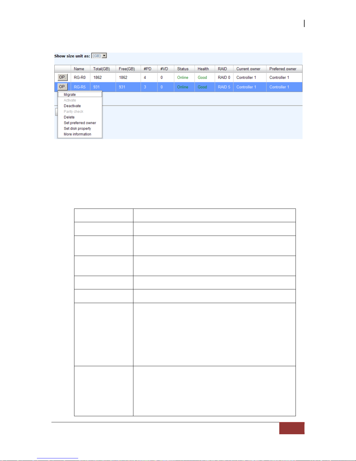
iSCSI GbE to SAS/SATA II RAID Subsystem
User Manual
69
Step 2: Confirm page. Click “OK” if all setups are correct.
There is a RAID 0 with 4 physical disks, named “RG-R0”. The second RAID group is a
RAID 5 with 3 physical disks, named “RG-R5”
Step 3: Done. View “RAID group” page.
RG column description:
The button includes the functions which can be excuted.
Name RAID group name.
Total(GB)(MB) Total capacity of this RAID group. The unit can be
displayed in GB or MB.
Free(GB) (MB) Free capacity of this RAID group. The unit can be
displayed in GB or MB.
#PD The number of physical disks in RAID group.
#VD The number of virtual disks in RAID group.
Status The status of RAID group.
“Online” the RAID group is online.
“Offline” the RAID group is offline.
“Rebuild” the RAID group is being rebuilt.
“Migrate” the RAID group is being migrated.
“Scrubbing” the RAID group is being scrubbed.
Health The health of RAID group.
“Good” the RAID group is good.
“Failed” the hard drive is failed.
“Degraded” the RAID group is not completed. The
reason could be lack of one disk or disk failure.
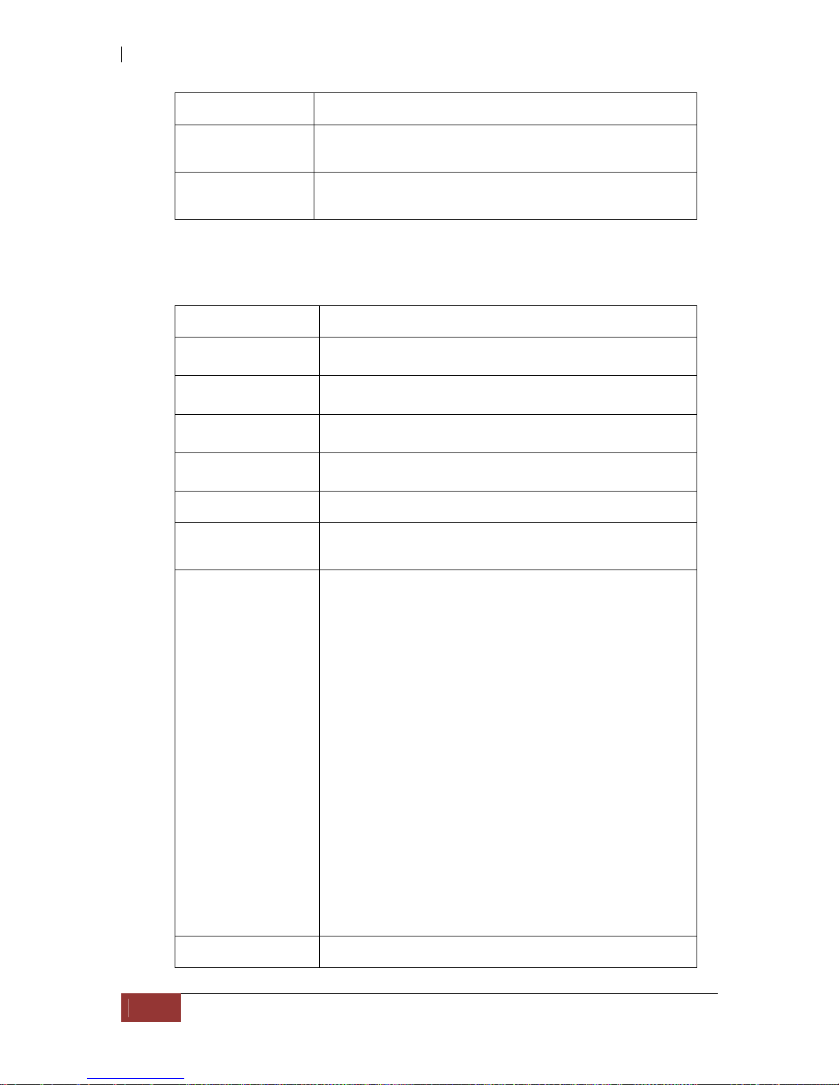
iSCSI GbE to SAS/SATA II RAID Subsystem
70
User Manual
RAID The RAID level of the RAID group.
Current owner The owner of the RAID group. Please refer to next
chapter for details.
Preferred owner The preferred owner of the RAID group. The default
owner is controller 1.
RG operations description:
Create
Create a RAID group.
Migrate
Change the RAID level of a RAID group. Please refer to
next chapter for details.
Activate
Activate a RAID group; it can be executed when RG
status is offline. This is for online roaming purpose.
Deactivate
Deactivate a RAID group; it can be executed when RG
status is online. This is for online roaming purpose.
Parity Check
Regenerate parity for the RAID group. It supports RAID
3 / 5 / 6 / 30 / 50 / 60.
Delete
Delete a RAID group.
Set preferred
owner
Set the RG ownership to the other controller.
Set disk property Change the disk property of write cache and standby
options.
Write cache:
“Enabled” Enable disk write cache. (Default)
“Disabled” Disable disk write cache.
Standby:
“Disabled” Disable auto spindown. (Default)
“30 sec / 1 min / 5 min / 30 min” En able
hard drive auto spindown to save power when no
access after certain period of time.
Read ahead:
“Enabled” Enable disk read ahead. (Default)
“Disabled” Disable disk read ahead.
Command queuing:
“Enabled” Enable disk command queue.
(Default)
“Disabled” Disable disk command queue.
More information
Show RAID group detail information.

iSCSI GbE to SAS/SATA II RAID Subsystem
User Manual
71
5.4.3 Virtual Disk
“Virtual disk” can view the status of each Virtual disk, create, and modify virtual disks.
The following is an example to create a VD.
Step 1: Click “Create”, enter “Name”, select RAID group from “RG name”, enter
required “Capacity (GB)/(MB)”, change “Stripe height (KB)”, change “Block size
(B)”, change “Read/Write” mode, set virtual disk “Priority”, select “Bg rate”
(Background task priority), and change “Readahead” option if necessary. “Erase”
option will wipe out old data in VD to prevent that OS recognizes the old partit ion. There
are three options in “Erase”: None (default), erase first 1GB or full disk. Last, select
“Type” mode for normal or clone usage. Then click “OK”.
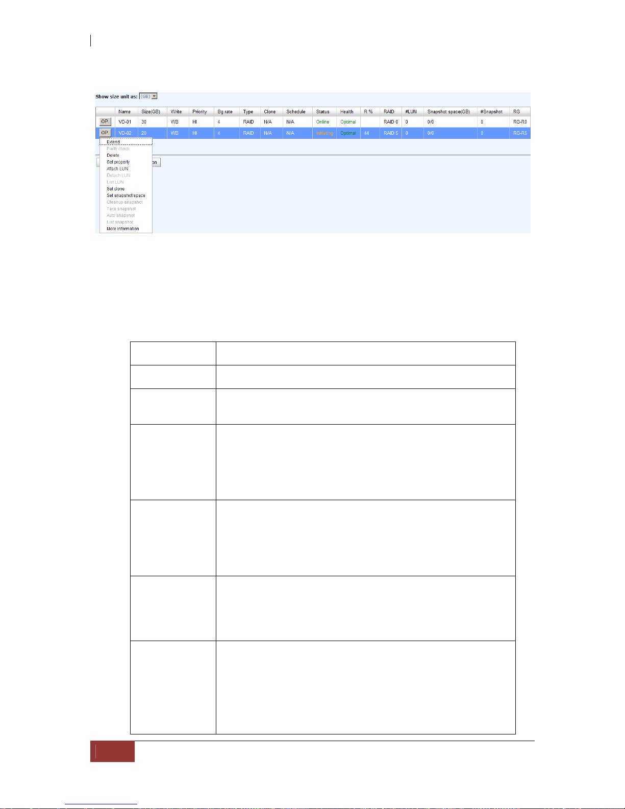
iSCSI GbE to SAS/SATA II RAID Subsystem
72
User Manual
Step 2: Confirm page. Click “OK” if all setups are correct.
Create a VD named “VD-01”, from “RG-R0”. The second VD is named “VD-02”, it’s
initializing.
Step 3: Done. View “Virtual disk” page.
VD column description:
The button includes the functions which can be executed.
Name Virtual disk name.
Size (GB)
(MB)
Total capacity of the virtual disk. The unit can be displayed
in GB or MB.
Right The right of virtual disk:
“WT” Write Through.
“WB” Write Back.
“RO” Read Only.
Priority The priority of virtual disk:
“HI” HIgh priority.
“MD” MiDdle priority.
“LO” LO w priority.
Bg rate Background task priority:
“4 / 3 / 2 / 1 / 0” Default value is 4. The higher
number the background priority of a VD is, the more
background I/O will be scheduled to execute.
Status The status of virtual disk:
“Online” The virtual disk is online.
“Offline” The virtual disk is offline.
“Initiating” The virtual disk is being initialized.
“Rebuild” The virtual disk is being rebuilt.
iSCSI GbE to SAS/SATA II RAID Subsystem
User Manual
73
“Migrate” The virtual disk is being migrated.
“Rollback” The virtual disk is being rolled back.
“Scrubbing” The virtual disk is being scrubbed.
“Parity checking” The virtual disk is being parity
check.
Type The type of virtual disk:
“RAID” the virtual disk is normal.
“BACKUP” the virtual disk is for clone usage.
Health The health of virtual disk:
“Optimal” the virtual disk is working well and
there is no failed disk in the RG.
“Degraded” At least one disk from the RG of the
Virtual disk is failed or plugged out.
“Failed” the RAID group disk of the VD has single
or multiple failed disks than its RAID level can recover
from data loss.
“Partially optimal” the virtual disk has
experienced recoverable read errors.
R %
Ratio (%) of initializing or rebuilding.
RAID RAID level.
#LUN Number of LUN(s) that virtual disk is attached to.
Snapshot
(GB) (MB)
The virtual disk size that is used for snapshot. The number
means “Used snapshot space” / “Total snapshot
space”. The unit can be displayed in GB or MB.
#Snapshot Number of snapshot(s) that have been taken.
RG name The RG name of the virtual disk
VD operations description:
Create Create a virtual disk.
Extend Extend a Virtual disk capacity.
Parity check Execute parity check for the virtual disk. It supports
RAID 3 / 5 / 6 / 30 / 50 / 60.
Regenerate parity:
“Yes” Regenerate RAID parity and write.
“No” Execute parity check only and find
mismatches. It will stop checking when mismatches
count to 1 / 10 / 20 / … / 100.

iSCSI GbE to SAS/SATA II RAID Subsystem
74
User Manual
Delete Delete a Virtual disk.
Set property Change the VD name, right, priority, bg rate and read
ahead.
Right:
“WT” Write Through.
“WB” Write Back. (Default)
“RO” Read Only.
Priority:
“HI” HIgh priority. (Default)
“MD” MiDdle priority.
“LO” LO w priority.
Bg rate:
“4 / 3 / 2 / 1 / 0” Default value is 4. The
higher number the background priority of a VD is,
the more background I/O will be scheduled to
execute.
Read ahead:
“Enabled” Enable disk read ahead. (Default)
“Disabled” Disable disk read ahead.
AV-media mode:
“Enabled” Enable AV-media mode for optimizing
video editing.
“Disabled”
Disable AV-media mode. (Default)
Type:
“RAID” the virtual disk is normal. (Default)
“Backup” the virtual disk is for clone usage.
Attach LUN Attach to a LUN.
Detach LUN Detach to a LUN.
List LUN List attached LUN(s).
Set Clone Set the target virtual disk for clone.
Clear Clone Clear clone function.
Start Clone Start clone function.
Stop Clone Stop clone function.
Schedule Clone Set clone function by schedule.
Set snapshot
space
Set snapshot space for executing snapshot. Please refer
to next chapter for more detail.

iSCSI GbE to SAS/SATA II RAID Subsystem
User Manual
75
Cleanup
snapshot
Clean all snapshot VD related to the Virtual disk and
release snapshot space.
Take snapshot Take a snapshot on the Virtual disk.
Auto snapshot Set auto snapshot on the Virtual disk.
List snapshot List all snapshot VD related to the Virtual disk.
More
information
Show Virtual disk detail information.
5.4.4 Snapshot
“Snapshot” can view the status of snapshot, create and modify snapshots. Please
refer to next chapter for more detail about snapshot concept. The following is an
example to take a snapshot.
Step 1: Create snapshot space. In “/ Volume configuration / Virtual disk”, move
the mouse pointer to the gray button next to the VD number; click “Set snapshot
space”.
Step 2: Set snapshot space. Then click “OK”. The snapshot space is created.
“VD-01” snapshot space has been created, snapshot space is 15GB, and used 1GB for
saving snapshot index.

iSCSI GbE to SAS/SATA II RAID Subsystem
76
User Manual
Step 3: Take a snapshot. In “/ Volume configuration / Snapshot”, click “Take
snapshot”. It will link to next page. Enter a snapshot name.
Step 4: Expose the snapshot VD. Move the mouse pointer to the gray button next to
the Snapshot VD number; click “Expose”. Enter a capacity for snapshot VD. If size is
zero, the exported snapshot VD will be read only. Otherwise, the exported snapshot VD
can be read / written, and the size will be the maximum capacity to read/write.
This is the list of snapshots in “VD-01”. There are two snapshots in “VD-01”. Snapshot
VD “SnapVD-01” is exported as read only, “SnapVD-02” is exported as read/write.
Step 5: Attach a LUN for snapshot VD. Please refer to the next section for attaching a
LUN.
Step 6: Done. Snapshot VD can be used.

iSCSI GbE to SAS/SATA II RAID Subsystem
User Manual
77
Snapshot column description:
The button includes the functions which can be executed.
Name Snapshot VD name.
Used (GB)
(MB)
The amount of snapshot space that has been used. The unit
can be displayed in GB or MB.
Status The status of snapshot:
“N/A” The snapshot is normal.
“Replicated” The snapshot is for clone or QReplica
usage.
“Abort” The snapshot is over space and abort.
Health The health of snapshot:
“Good” The snapshot is good.
“Failed” The snapshot fails.
Exposure Snapshot VD is exposed or not.
Right The right of snapshot:
“RW” Read / Write. The snapshot VD can be read /
write.
“RO” Read Only. The snapshot VD is read only.
#LUN Number of LUN(s) that snapshot VD is attached.
Created time Snapshot VD created time.
Snapshot operation description:
Expose/
Unexpose
Expose / unexpose the snapshot VD.
Rollback Rollback the snapshot VD.
Delete Delete the snapshot VD.
Attach Attach a LUN.
Detach Detach a LUN.
List LUN List attached LUN(s).

iSCSI GbE to SAS/SATA II RAID Subsystem
78
User Manual
5.4.5 Logical Unit
“Logical unit” can view, create, and modify the status of attached logical unit number(s)
of each VD.
User can attach LUN by clicking the “Attach”. “Host” must enter with an iSCSI node
name for access control, or fill-in wildcard “*”, which means every host can access the
volume. Choose LUN number and permission, and then click “OK”.
VD-01 is attached to LUN 0 and every host can access. VD-02 is attached to LUN 1 and
only initiator node which is named “iqn.1991-05.com.microsoft:win-r6qrvqjd5m7” can
access.
LUN operations description:
Attach Attach a logical unit number to a Virtual disk.
Detach Detach a logical unit number from a Virtual disk.
The matching rules of access control are inspected from top to bottom in sequence. For
example: there are 2 rules for the same VD, one is “*”, LUN 0; and the other is
“iqn.host1”, LUN 1. The other host “iqn.host2” can login successfully because it
matches rule 1.
The access will be denied when there is no matching rule.

iSCSI GbE to SAS/SATA II RAID Subsystem
User Manual
79
5.4.6 Example
The following is an example for creating volumes. Example 1 is to create two VDs and
set a global spare disk.
Example 1
Example 1 is to create two VDs in one RG, each VD uses global cache volume. Global
cache volume is created after system boots up automatically. So, no action is needed
to set CV. Then set a global spare disk. Eventually, delete all of them.
Step 1: Create RG (RAID group).
To create the RAID group, please follow these steps:
1. Select “/ Volume configuration / RAID group”.
2. Click “Create”.
3. Input an RG Name, choose a RAID level from the list, click “Select PD” to
choose the RAID PD slot(s), then click “OK”.
4. Check the outcome. Click “OK” if all setups are correct.
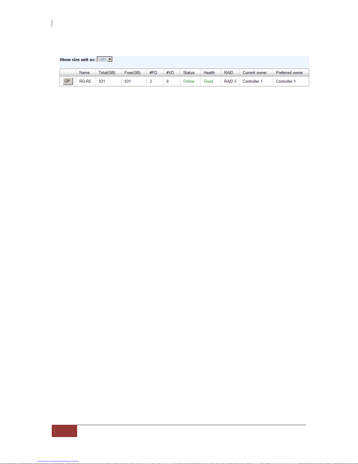
iSCSI GbE to SAS/SATA II RAID Subsystem
80
User Manual
5. Done. RG has been created.
A RAID 5 RG named “RG-R5” with 3 physical disks is created.
Step 2: Create VD (Virtual disk).
To create a data user volume, please follow these steps.
1. Select “/ Volume configuration / Virtual disk”.
2. Click “Create”.
3. Input a VD name, choose the RG when VD will be created, enter the VD
capacity, select the stripe height, block size, read/write mode, set priority,
modify Bg rate if necessary, and finally click “OK”.
4. Done. A VD has been created.
5. Repeat steps 1 to 4 to create another VD.
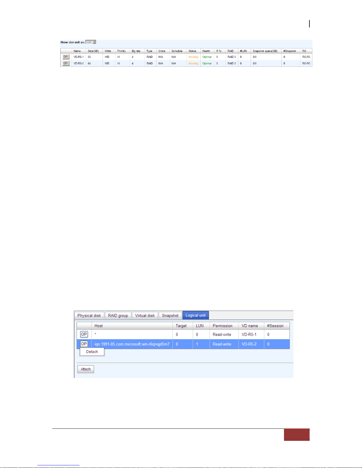
iSCSI GbE to SAS/SATA II RAID Subsystem
User Manual
81
Two VDs, “VD-R5-1” and “VD-R5-2”, were created from RG “RG-R5”. The size of “VD-
R5-1” is 50GB, and the size of “VD-R5-2” is 64GB. There is no LUN attached.
Step 3: Attach LUN to VD.
There are 2 methods to attach LUN to VD.
1. In “/ Volume configuration / Virtual disk”, move the mouse pointer to the
gray button next to the VD number; click “Attach LUN”.
2. In “/ Volume configuration / Logical unit”, click “Attach”.
The steps are as follows:
1. Select a VD.
2. Input “Host” name, which is a FC node name for access control, or fill-in
wildcard “*”, which means every host can access to this volume. Choose LUN
and permission, and then click “OK”.
3. Done.
VD-R5-1 is attached to LUN 0. VD-R5-2 is attached LUN 1.
NOTE: The matching rules of access control are from the LUNs’
created time, the earlier created LUN is prior to the matching rules.
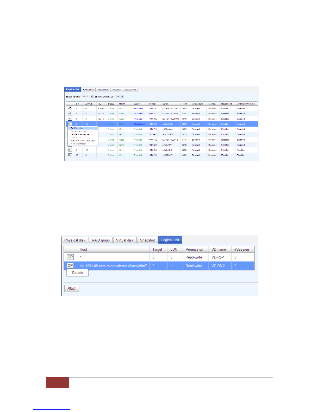
iSCSI GbE to SAS/SATA II RAID Subsystem
82
User Manual
Step 4: Set global spare disk.
To set global spare disks, please follow the procedures.
1. Select “/ Volume configuration / Physical disk”.
2. Check the gray button next to the PD slot; click “Set global space”.
3. “Global spare” status is shown in “Usage” column.
Slot 4 is set as global spare disk (GS).
Step 5: Done. LUNs can be used as disks.
To delete VDs, RG, please follow the steps listed below.
Step 6: Detach LUN from VD.
In “/ Volume configuration / Logical unit”,
1. Move the mouse pointer to the gray button next to the LUN; click “Detach”.
There will pop up a confirmation page.
2. Choose “OK”.
3. Done.

iSCSI GbE to SAS/SATA II RAID Subsystem
User Manual
83
Step 7: Delete VD (Virtual disk).
To delete the Virtual disk, please follow the procedures:
1. Select “/ Volume configuration / Virtual disk”.
2. Move the mouse pointer to the gray button next to the VD number; click
“Delete”. There will pop up a confirmation page, click “OK”.
3. Done. Then, the VDs are deleted.
NOTE: When deleting VD, the attached LUN(s) related to this VD
will be detached automatically.
Step 8: Delete RG (RAID group).
To delete the RAID group, please follow the procedures:
1. Select “/ Volume configuration / RAID group”.
2. Select a RG which all its VD are deleted, otherwise the this RG cannot be
deleted.
3. Check the gray button next to the RG number click “Delete”.
4. There will pop up a confirmation page, click “OK”.
5. Done. The RG has been deleted.
NOTE: The action of deleting one RG will succeed only when all of
the related VD(s) are deleted in this RG. Otherwise, it will have an
error when deleting this RG.
Step 9: Free global spare disk.
To free global spare disks, please follow the procedures.
1. Select “/ Volume configuration / Physical disk”.
2. Check the gray button next to the PD slot; click “Set Free disk”.
Step 10: Done, all volumes have been deleted.
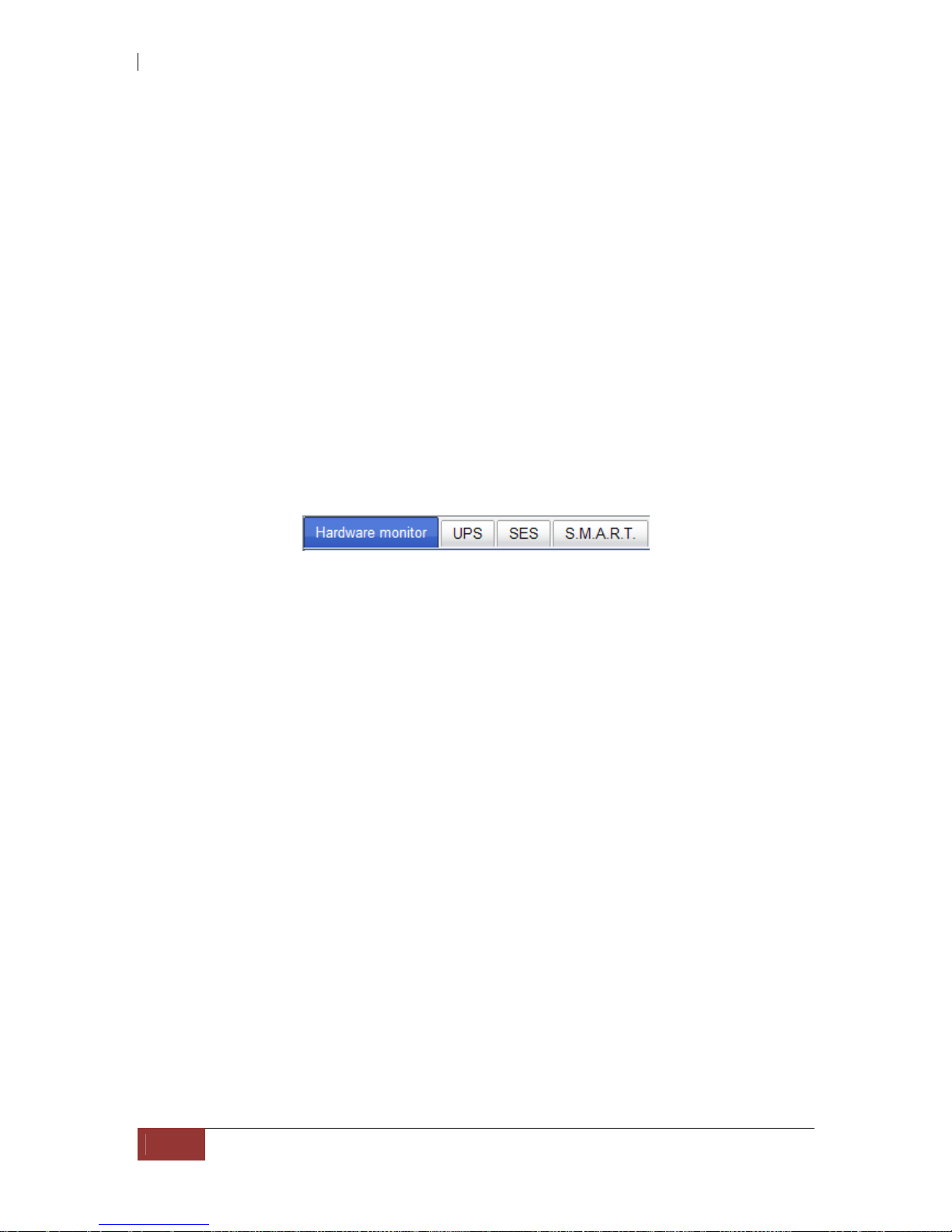
iSCSI GbE to SAS/SATA II RAID Subsystem
84
User Manual
5.5 Enclosure Management
“Enclosure management” allows managing enclosure information including “SES
configuration”, “Hardware monitor”, “S.M.A.R.T.” and “UPS”. For th e enclosure
management, there are many sensors for different purposes, such as temperature
sensors, voltage sensors, hard disks, fan sensors, power sensors, and LED status. Due
to the different hardware characteristics among these sensors, they have different
polling intervals. Below are the details of polling time intervals:
1. Temperature sensors: 1 minute.
2. Voltage sensors: 1 minute.
3. Hard disk sensors: 10 minutes.
4. Fan sensors: 10 seconds . When there are 3 errors consecutively, controller
sends ERROR event log.
5. Power sensors: 10 seconds, when there are 3 errors consecutively, controller
sends ERROR event log.
6. LED status: 10 seconds.
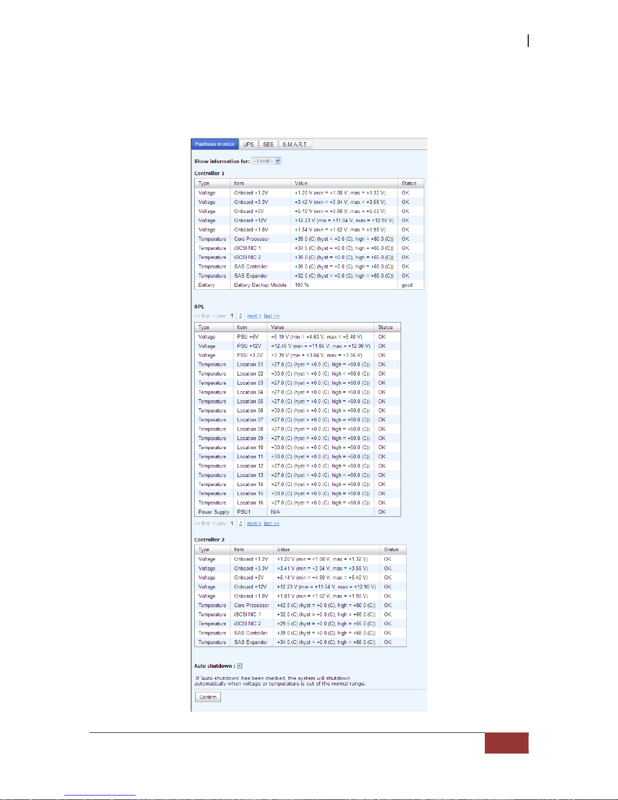
iSCSI GbE to SAS/SATA II RAID Subsystem
User Manual
85
5.5.1 Hardware Monitor
“Hardware monitor” can be used to view the information of current voltage,
temperature levels, and fan speed.
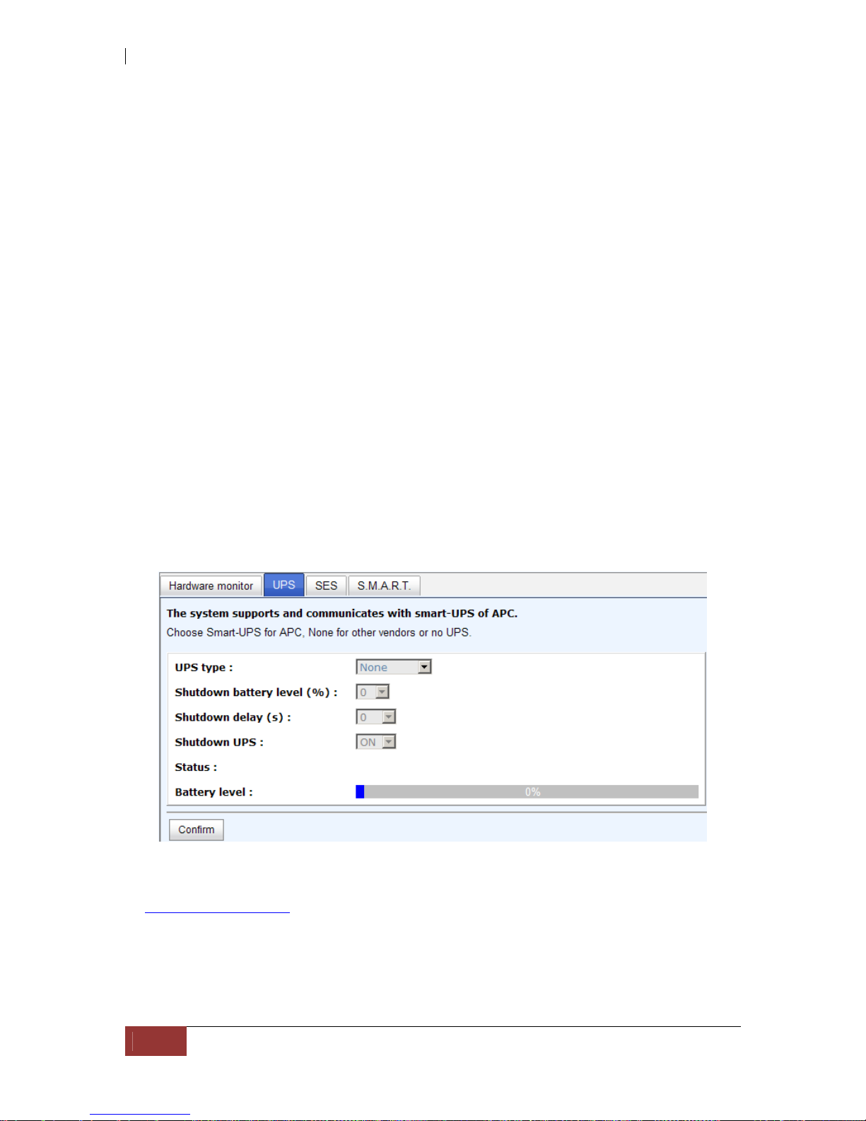
iSCSI GbE to SAS/SATA II RAID Subsystem
86
User Manual
If “Auto shutdown” has been checked, the system will shutdown automatically when
voltage or temperature is out of the normal range. For better data protection, please
check “Auto Shutdown”.
For better protection and avoiding single short period of high temperature triggering
auto shutdown, the RAID controller evaluates multiple conditions for triggering auto
shutdown. Below are the details of when the Auto shutdown will be t r iggered.
1. There are 3 sensors placed on controller for temperature checking, they are on
core processor, PCI-X bridge, and daughter board. Controller will check each
sensor for every 30 seconds. When one of these sensors is over high
temperature value continuously for 3 minutes, auto shutdown will be triggered
immediately.
2. The core processor temperature limit is 85°C. The PCI-X bridge temperature
limit is 80°C. The daughter board temperature limit is 80°C.
3. If the high temperature situation doesn’t last for 3 minutes, controller will not
do auto shutdown.
5.5.2 UPS
“UPS” is used to set up UPS (Uninterruptible Power Supply).
Currently, the system only supports and communicates with APC (American Power
Conversion Corp.) smart UPS. Please review the details from the website:
http://www.apc.com/.
First, connect the system and APC UPS via RS-232 for communication. Then set up the
shutdown values (shutdown battery level %) when power is failed. UPS in other
companies can work well, but they have no such communication feature with the
system.
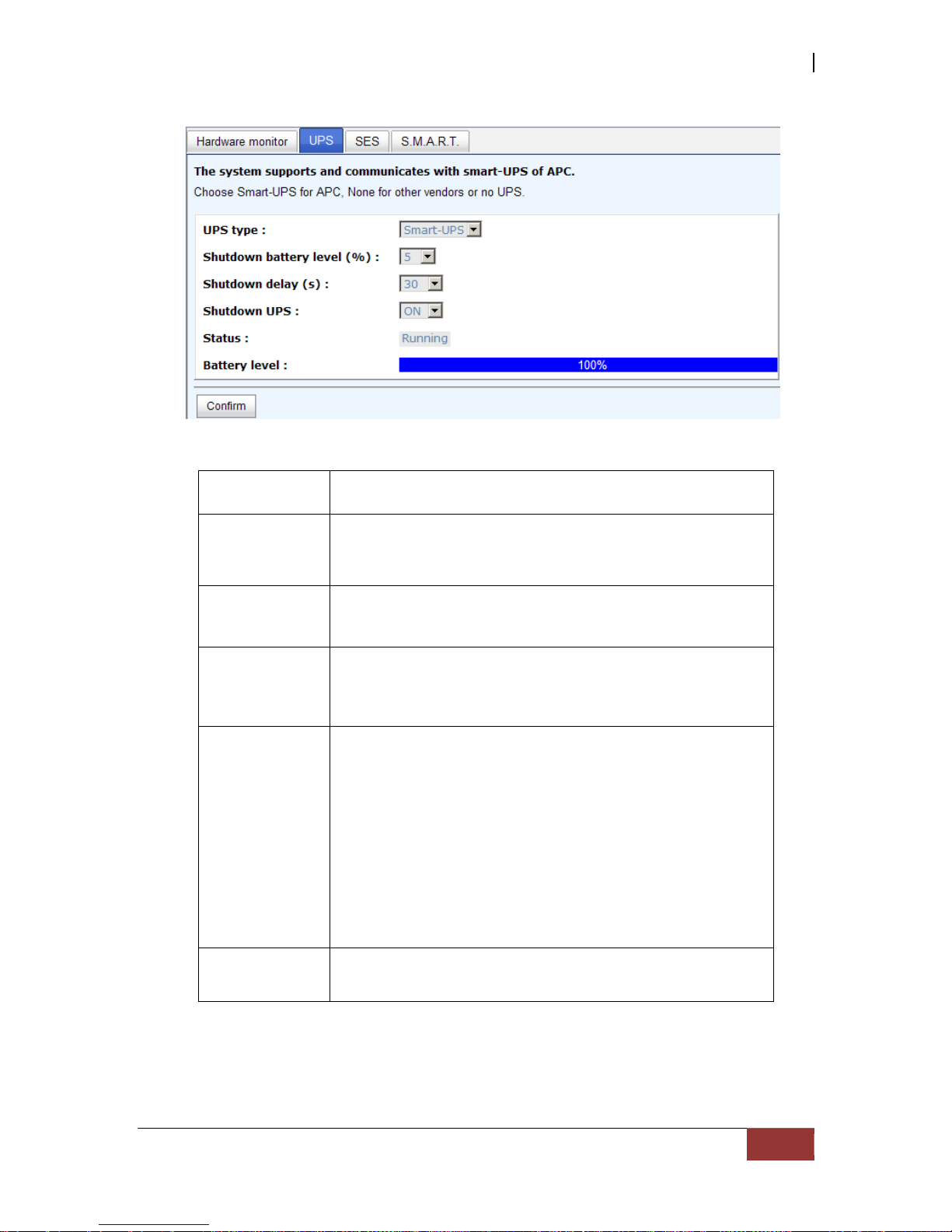
iSCSI GbE to SAS/SATA II RAID Subsystem
User Manual
87
UPS Type
Select UPS Type. Choose Smart-UPS for APC, None for
other vendors or no UPS.
Shutdown
Battery Level
(%)
When below the setting level, system will shutdown .
Setting level to “0” will disable UPS.
Shutdown
Delay (s)
If power failure occurred, and system can not return to
value setting status, the system will shutdown. Setting
delay to “0” will disable the function.
Shutdown
UPS
Select ON, when power is gone, UPS will shutdown by
itself after the system shutdown successfully. After power
comes back, UPS will start working and notify system to
boot up. OFF will not.
Status The status of UPS.
“Detecting…”
“Running”
“Unable to detect UPS”
“Communication lost”
“UPS reboot in progress”
“UPS shutdown in progress”
“Batteries failed. Please change them NOW!”
Battery Level
(%)
Current percentage of battery level.
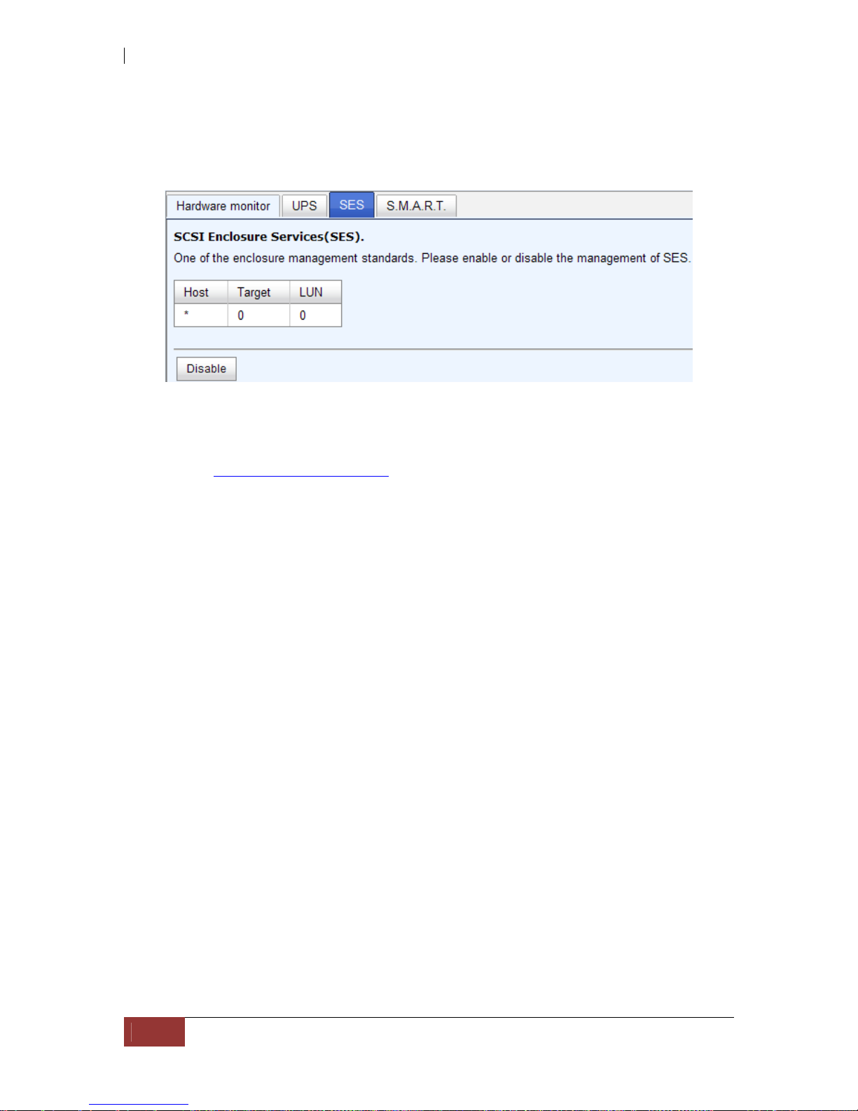
iSCSI GbE to SAS/SATA II RAID Subsystem
88
User Manual
5.5.3 SES
SES represents SCSI Enclosure Services, one of the enclosure management standards.
“SES configuration” can enable or disable the management of SES.
Enable SES in LUN 0, and can be accessed from every host
The SES client software is available at the following web site:
SANtools: http://www.santools.com/
5.5.4 Hard Drive S.M.A.R.T. Support
S.M.A.R.T. (Self-Monitoring Analysis and Reporting Technology) is a diagnostic tool
for hard drives to deliver warning of drive failures in advance. S.M.A.R.T. provides
users chances to take actions before possible drive failure.
S.M.A.R.T. measures many attributes of the hard drive all the time and inspects the
properties of hard drives which are close to be out of tolerance. The advanced notice of
possible hard drive failure can allow users to back up hard drive or replace the hard
drive. This is much better than hard drive crash when it is w riting data or rebuilding a
failed hard drive.
“S.M.A.R.T.” can display S.M.A.R.T. information of hard drives. The number is the
current value; the number in parenthesis is the threshold value. The threshold values
of hard drive vendors are different; please refer to vendors’ specification for details.
S.M.A.R.T. only supports SATA drive. SAS drive does not have. It will show N/A in this
web page.
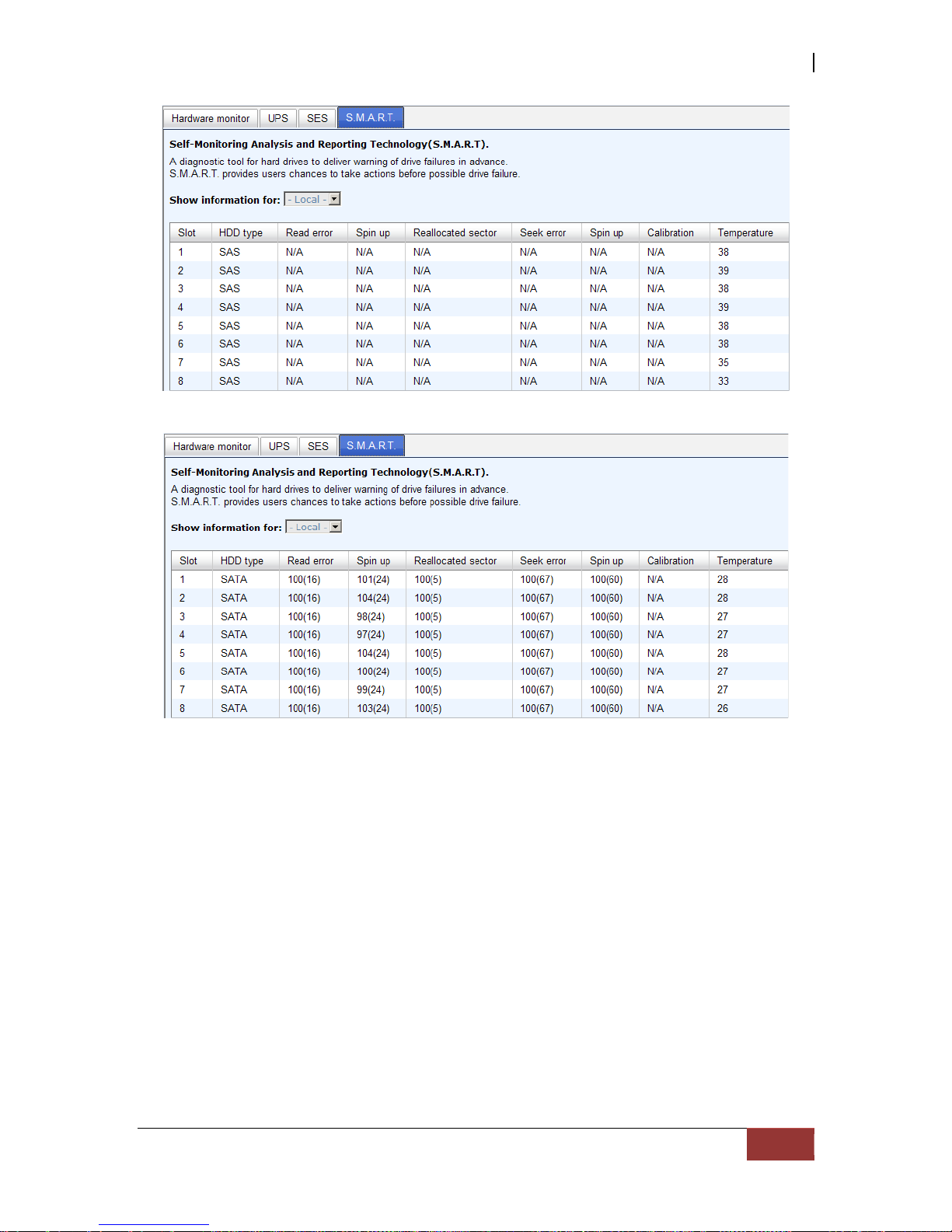
iSCSI GbE to SAS/SATA II RAID Subsystem
User Manual
89

iSCSI GbE to SAS/SATA II RAID Subsystem
90
User Manual
5.6 System Maintenance
“Maintenance” allows the operations of system functions which include “System
information” to show the system version and details, “Event log” to view system
event logs to record critical events, “Upgrade” to the latest firmware, “Firmware
synchronization” to synchronized firmware versions on both controllers, “Reset to
factory default” to reset all controller configuration values to factory settings, “Import
and export” to import and export all controller configuration to a file, and “Reboot and
shutdown” to reboot or shutdown the system.
5.6.1 System Information
“System information” can display system information, including CPU type, installed
system memory, firmware version, serial numbers of dual controllers, backplane ID, and
system status.
Status description:
Normal Dual controllers are in normal stage.
Degraded One controller fails or has been plugged out..
Lockdown The firmware of two controllers is different or the size of
memory of two controllers is different.
Single Single controller mode.
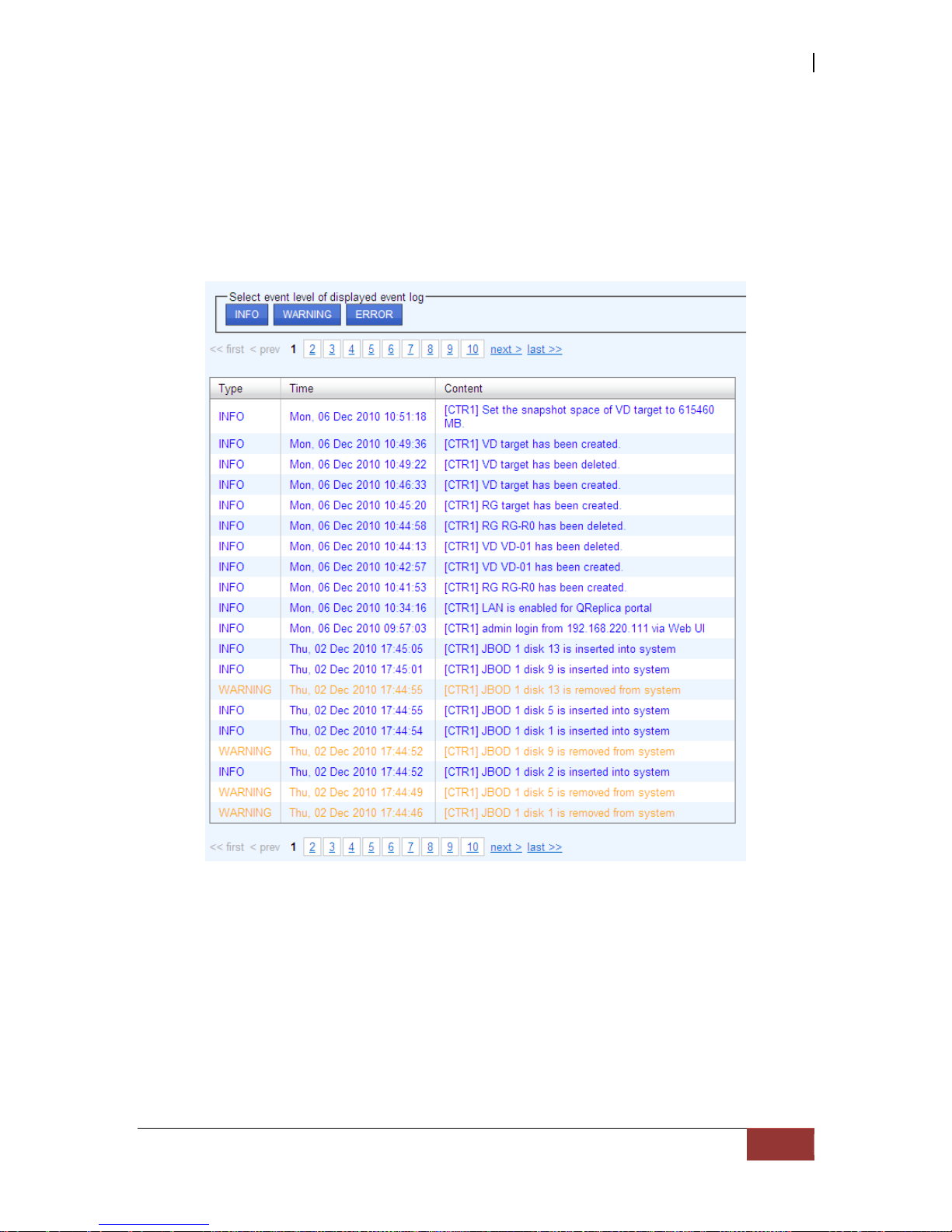
iSCSI GbE to SAS/SATA II RAID Subsystem
User Manual
91
5.6.2 Event Log
“Event log” can view the event messages. Check the checkbox of INFO, WARNING, and
ERROR to choose the level of event log display. Click “Download” button to save the
whole event log as a text file with file name “log-ModelName-SerialNumber-DateTime.txt”. Click “Clear” button to clear all event logs. Click “Mute” button to stop alarm
if system alerts.
The event log is displayed in reverse order which means the latest event log is on the
first page. The event logs are actually saved in the first four hard drives; each hard
drive has one copy of event log. For one controller, there are four copies of event logs
to make sure users can check event log any time when there is/are failed disk(s).
NOTE: Please plug-in any of the first four hard drives, then event
logs can be saved and displayed in next system boot up. Otherwise,
the event logs would disappear.

iSCSI GbE to SAS/SATA II RAID Subsystem
92
User Manual
5.6.3 Upgrade
“Upgrade” can upgrade firmware. Please prepare new firmware file named “xxxx.bin”
in local hard drive, then click “Browse” to select the f ile. Click “Confirm”, it will pop up
a message “Upgrade system now? If you want to downgrade to the previous FW later
(not recommend), please export your system configuration in advance”, click “Cancel”
to export system configuration in advance, then click “OK” to start to upgrade firmware.
When upgrading, there is a progress bar running. After finished upgrading, the system
must reboot manually to make the new firmware took effect.
NOTE: Please contact your vendor for the latest firmware.

iSCSI GbE to SAS/SATA II RAID Subsystem
User Manual
93
5.6.4 Firmware Synchronization
“Firmware synchronization” can synchronize the firmware version when controller 1
and controller 2’s firmware are different. In normal status, the firmware versions in
controller 1 and 2 are the same as below figure.
5.6.5 Reset to Factory Default
“Reset to factory default” allows user to reset controller to factory default setting.
Reset to default value, the password is: 00000000, and IP address to default DHCP.

iSCSI GbE to SAS/SATA II RAID Subsystem
94
User Manual
5.6.6 Import and Export
“Import and export” allows user to save system configuration values: export, and
apply all configuration: import. For the volume configuration setting, the values are
available in export and not available in import which can avoid confliction / date-deleting
between two controllers which mean if one system already has valuable volumes in the
disks and user may forget and overwrite it. Use import could return to original
configuration. If the volume setting was also imported, user’s current volumes will be
overwritten with different configuration.
1. Import: Import all system con figurations excluding volume configuration.
2. Export: Export all configurations to a file.
WARNING: “Import” will import all system configurations
excluding volume configuration; the current configurations will be
replaced.
5.6.7 Reboot and Shutdown
“Reboot and shutdown” displays “Reboot” and “Shutdown” buttons. Before
power off, it’s better to execute “Shutdown” to flush the data from cache to physical
disks. The step is necessary for data protection.

iSCSI GbE to SAS/SATA II RAID Subsystem
User Manual
95
5.7 Home/Logout/Mute
In the right-upper corner of web UI, there are 3 individual icons, “Home”, “Logout”,
and “Mute”.
5.7.1 Home
Click “Home” to return to home page
5.7.2 Logout
For security reason, please use “Logout” to exit the web UI. To re-login the system,
please enter username and password again.
5.7.3 Mute
Click “Mute” to stop the alarm when error occurs.

iSCSI GbE to SAS/SATA II RAID Subsystem
96
User Manual
Chapter 6 Advanced Operations
6.1 Volume Rebuild
If one physical disk from a RG, which is set to a protected RAID level (e.g. RAID 3,
RAID 5, or RAID 6), failed or has been unplugged/removed, the status of RG is
changed to degraded mode. The system will search/detect spare disk to rebuild the
degraded RG to become normal/complete. It will detect dedicated spare disk as rebuild
disk first, then global spare disk.
The iSCSI RAID subsystem supports Auto-Rebuild. The following is the scenario:
Take RAID 6 for example:
1. When there is no global spare disk or dedicated spare disk in the system,
controller will be in degraded mode and wait until (A) there is one disk
assigned as spare disk, or (B) the failed disk is removed and replaced with
new clean disk, then the Auto-Rebuild starts. The new disk will be a spare disk
to the original RG automatically.
If the new added disk is not clean (with other RG information), it would be
marked as RS (reserved) and the system will not start "auto-rebuild".
If this disk is not belonging to any existing RG, it would be FR (Free) disk and
the system will start Auto-Rebuild.
If user only removes the failed disk and plugs the same failed disk in the same
slot again, the auto-rebuild will start running. But rebuildin g in the same f ailed
disk may impact customer data if the status of disk is unstable. It is
recommended for users not to rebuild in the failed disk for better data
protection.
2. When there is enough global spare disk(s) or dedicated spare disk(s) for the
degraded array, the system starts Auto-Rebuild immediately. And in RAID 6, if
another disk failure occurs during rebuilding, the system will start the above
Auto-Rebuild process as well. Auto-Rebuild feature only works when the status
of RG is "Online". It will not work at “Offline” status. Thus, it will not conflict
with the “Roaming”.
3. In degraded mode, the status of RG is “Degraded”. When rebuilding, the
status of RG/VD will be “Rebuild”, the column “R%” in VD will display the
ratio in percentage. After completing the rebuilding process, the status will
become “Online”. RG will become complete or normal.
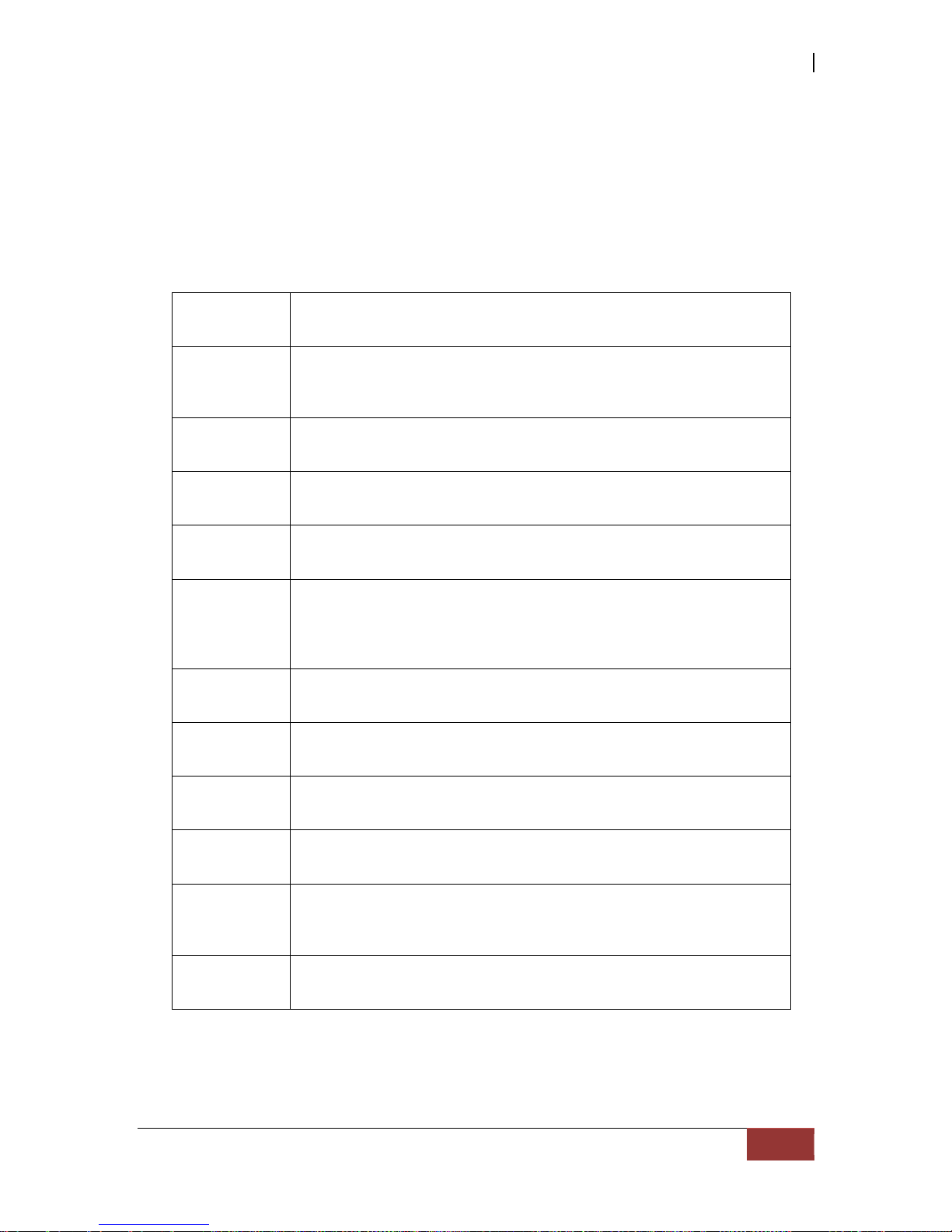
iSCSI GbE to SAS/SATA II RAID Subsystem
User Manual
97
NOTE: “Set dedicated spare” is not available if there is no RG, or if
RG is set to RAID 0 or JBOD, because user can not set dedicated
spare disk to RAID 0 & JBOD.
Sometimes, rebuild is called recover; they are the same meaning. The following table
is the relationship between RAID levels and rebuild.
RAID 0 Disk striping. No protection for data. RG fails if any hard drive
fails or unplugs.
RAID 1 Disk mirroring over 2 disks. RAID 1 allows one hard drive fails or
unplugging. Need one new hard drive to insert to the system and
rebuild to be completed.
N-way
mirror
Extension to RAID 1 level. It has N copies of the disk. N-way
mirror allows N-1 hard drives failure or unplu gging.
RAID 3 Striping with parity on the dedicated disk. RAID 3 allows one
hard drive failure or unplugging.
RAID 5 Striping with interspersed parity over the member disks. RAID 5
allows one hard drive failure or unplugging.
RAID 6 2-dimensional parity protection over the member disks. RAID 6
allows two hard drives failure or unplugging. If it needs to rebuild
two hard drives at the same time, it will rebuild the first one,
then the other in sequence.
RAID 0+1 Mirroring of RAID 0 volumes. RAID 0+1 allows two hard drive
failures or unplugging, but at the same array.
RAID 10 Striping over the member of RAID 1 volumes. RAID 10 allows
two hard drive failure or unplugging, but in different arrays.
RAID 30 Striping over the member of RAID 3 volumes. RAID 30 allows
two hard drive failure or unplugging, but in different arrays.
RAID 50 Striping over the member of RAID 5 volumes. RAID 50 allows
two hard drive failures or unplugging, but in different arrays.
RAID 60 Striping over the member of RAID 6 volumes. RAID 40 allows
four hard drive failures or unplugging, every two in different
arrays.
JBOD The abbreviation of “Just a Bunch Of Disks”. No data protection.
RG fails if any hard drive failures or unplugs.
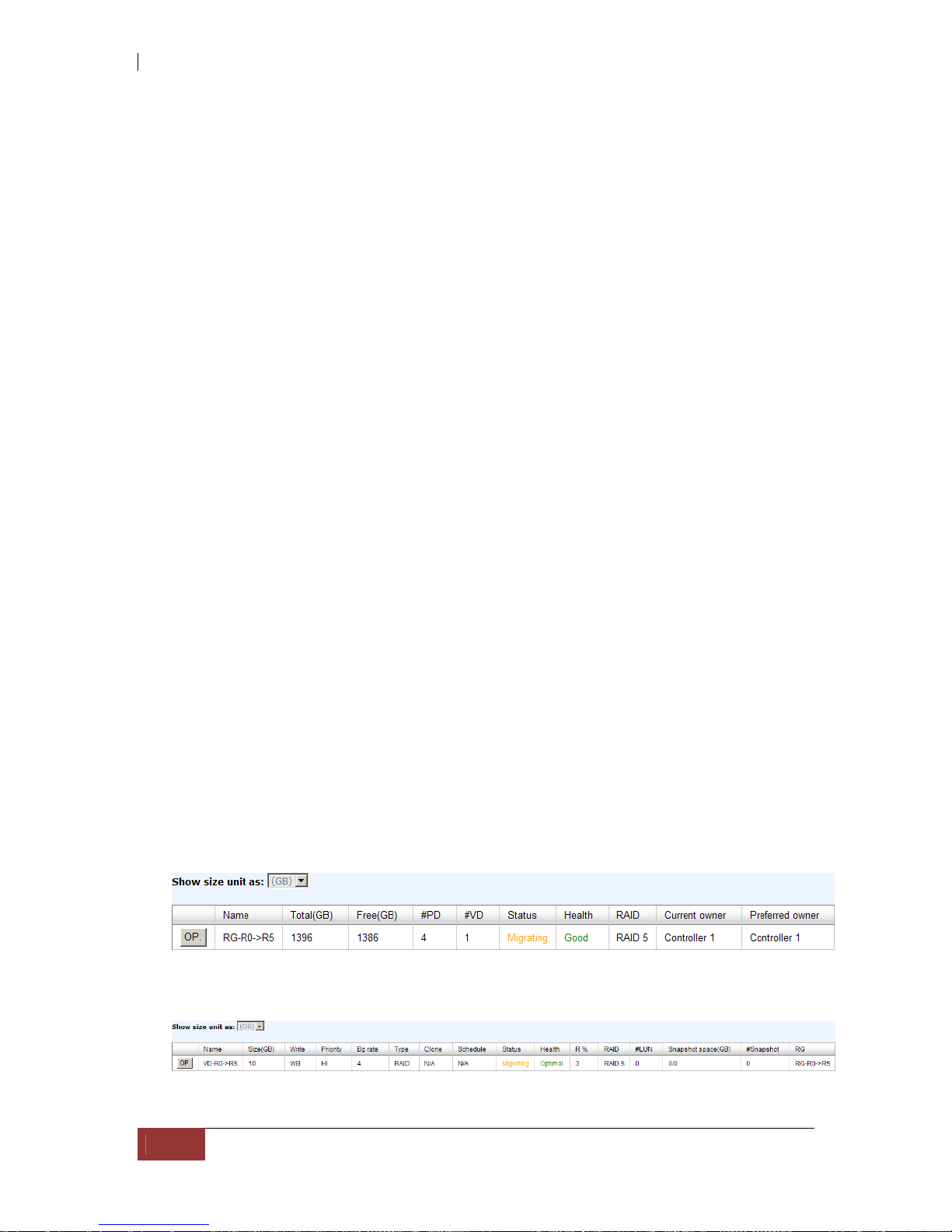
iSCSI GbE to SAS/SATA II RAID Subsystem
98
User Manual
6.2 RG Migration
To migrate the RAID level, please follow the steps below.
1. Select “/ Volume configuration / RAID group”.
2. Check the gray button next to the RG number; click “Migrate”.
3. Change the RAID level by clicking the down arrow to “RAID 5”. There will be
a pup-up which indicates that HDD is not enough to support the new setting of
RAID level, click “Select PD” to increase hard drives, then click “OK “ to go
back to setup page. When doing migration to lower RAID level, such as the
original RAID level is RAID 6 and user wants to migrate to RAID 0, system will
evaluate whether this operation is safe or not, and appear a message of
"Sure to migrate to a lower protection array?” to give user warning.
4. Double check the setting of RAID level and RAID PD slot. If there is no
problem, click “OK“.
5. Finally a confirmation page shows the detail of RAID information. If there is no
problem, click “OK” to start migration. System also pops up a message of
“Warning: power lost during migration may cause d amage of data!” to
give user warning. When the power is abnormally off during the migration, the
data is in high risk.
6. Migration starts and it can be seen from the “status” of a RG with
“Migrating”. In “/ Volume configuration / Virtual disk”, it displays a
“Migrating” in “Status” and complete percentage of migration in “R%”.
A RAID 0 with 3 physical disks migrates to RAID 5 with 4 physical disks.

iSCSI GbE to SAS/SATA II RAID Subsystem
User Manual
99
To do migration, the total size of RG must be larger or equal to the original RG. It does
not allow expanding the same RAID level with the same hard disks of original RG.
The operation is not allowed when RG is being migrated. System would reject following
operations:
1. Add dedicated spare.
2. Remove a dedicated spare.
3. Create a new VD.
4. Delete a VD.
5. Extend a VD.
6. Scrub a VD.
7. Perform yet another migration operation.
8. Scrub entire RG.
9. Take a new snapshot.
10. Delete an existing snapshot.
11. Export a snapshot.
12. Rollback to a snapshot.
IMPORTANT! RG Migration cannot be executed during rebuild or
VD extension.
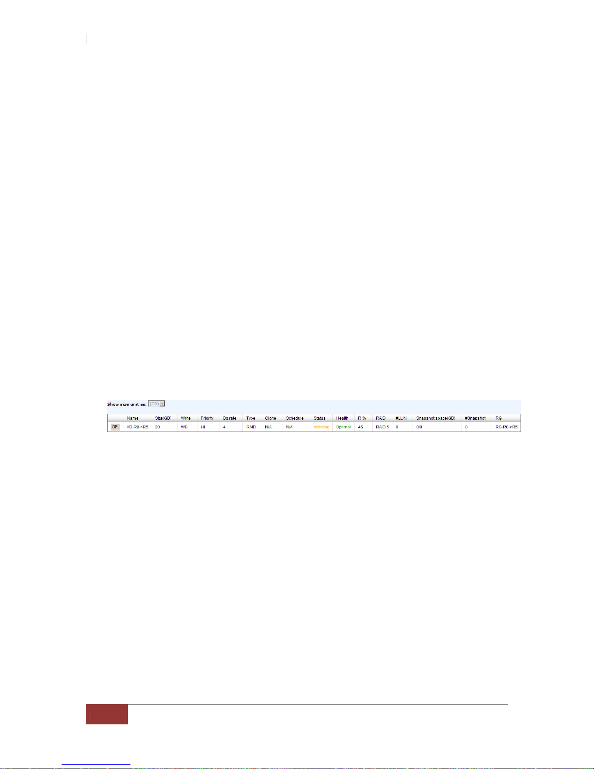
iSCSI GbE to SAS/SATA II RAID Subsystem
100
User Manual
6.3 VD Extension
To extend VD size, please follow the procedures.
1. Select “/ Volume configuration / Virtual disk”.
2. Check the gray button next to the VD number; click “Extend”.
3. Change the size. The size must be larger than th e original, an d then click “ OK”
to start extension.
4. Extension starts. If VD needs initialization, it will display “Initiating” in
“Status” and the completed percentage of initialization in “R%” column.
NOTE: The size of VD extension must be larger than original.
IMPORTANT! VD Extension cannot be executed during rebuild or
migration.
 Loading...