

Page 1
2 -Wire Intercom System
PRO591/592 User Manual
3529,6,216(&85,7<352'8&76
5(9
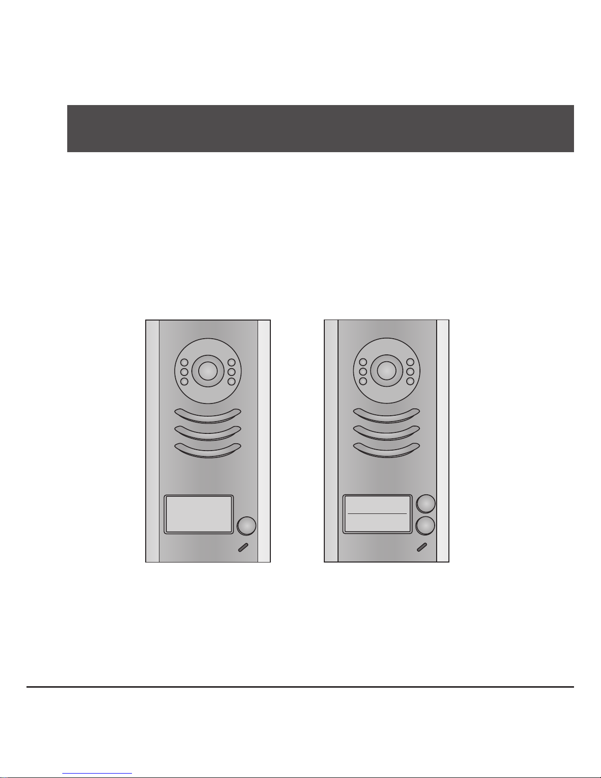
PRO591 PRO592
Page 2

CONTENTS
1.Parts and Functions............................................................................................. 1
2.Terminal Descriptions .......................................................................................... 1
3.Specications ...................................................................................................... 2
4.Mounting .............................................................................................................. 2
4.1 Mounting Without Rainy Cover ...................................................................... 2
4.2 Mounting With Rainy Cover ........................................................................... 3
4.3 Placing Name Label ...................................................................................... 3
4.4 Adjusting Camera Angle ................................................................................ 4
5.System Wiring and Connections ......................................................................... 4
5.1 Basic Connection........................................................................................... 4
5.2 Electric Lock Connection ............................................................................... 5
5.2.1 Door Lock Controlled with Internal Power ............................................ 5
5.2.2 Door Lock Controlled with Dry Contact ................................................ 5
5.2.3 How to setup the unlock parameter in Monitor ...................................... 6
5.3 Multi Doorstations Connection....................................................................... 7
5.4 Multi Monitors Connection ............................................................................. 8
5.4.1 Basic IN-OUT Wiring Mode ................................................................. 8
5.4.2 With PRODBC-4 Wiring Mode ............................................................. 9
6.Setup ................................................................................................................... 10
6.1 DIP Switches Settings of Doorstation ............................................................ 10
6.2 DIP Switches Settings of Monitor .................................................................. 10
6.3 Notices........................................................................................................... 12
7.Cables Requirements .......................................................................................... 13
Page 3
-1-
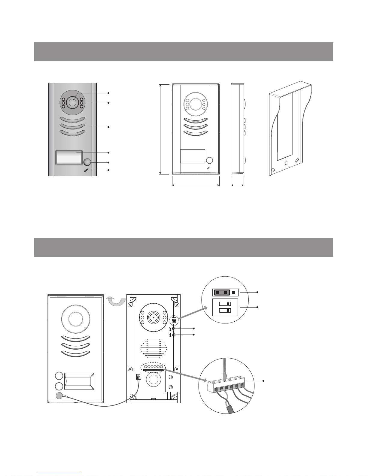
1.Parts and Functions
Rainy Cover
Camera Lens
Night View LED
Speaker
Nameplate
Call Button
Microphone
90 mm
176 mm
23 mm
2.Terminal Descriptions
BUS
PL
S1+ S2+ S-
1 2
ON
12
ON
MIC adjustment
Lock Control Jumper
Doorstation Code DIP
Main Connect Port
1 2 3
SPK adjustment
Note: 352592 has two call buttons.
Page 4
-2-
•
Lock Control Jumper:
To select the lock type: see 5.2.1 , 5.2.2
•
Doorstation Code DIP:
Total 4 doorstations can be supported,see 6.1
•
Main Connect Port:
To connect the bus line and the electronic locks.
• BUS: Connect to the bus line, no polarity.
• PL: External lock power input, connect to the power positive(power +).
• S1+, S2+: Lock power(+) output, to connect 2 locks.
• S-: Lock power(-) output, connect to the power(-) input of locks(only when using the camera to
power the locks, if using the external power supply for the locks, the S- will not be connected).
3.Specications
Lock Power supply: 12Vdc, 300mA(Internal Power)
Power Consumtion: 1W in standby, 12W in working
NO, COM dry contact: Max. 48V dc 1.5A
Unlocking time: 1 to 9 seconds, set by Monitor
Working temperature: -10ºC ~ 45ºC
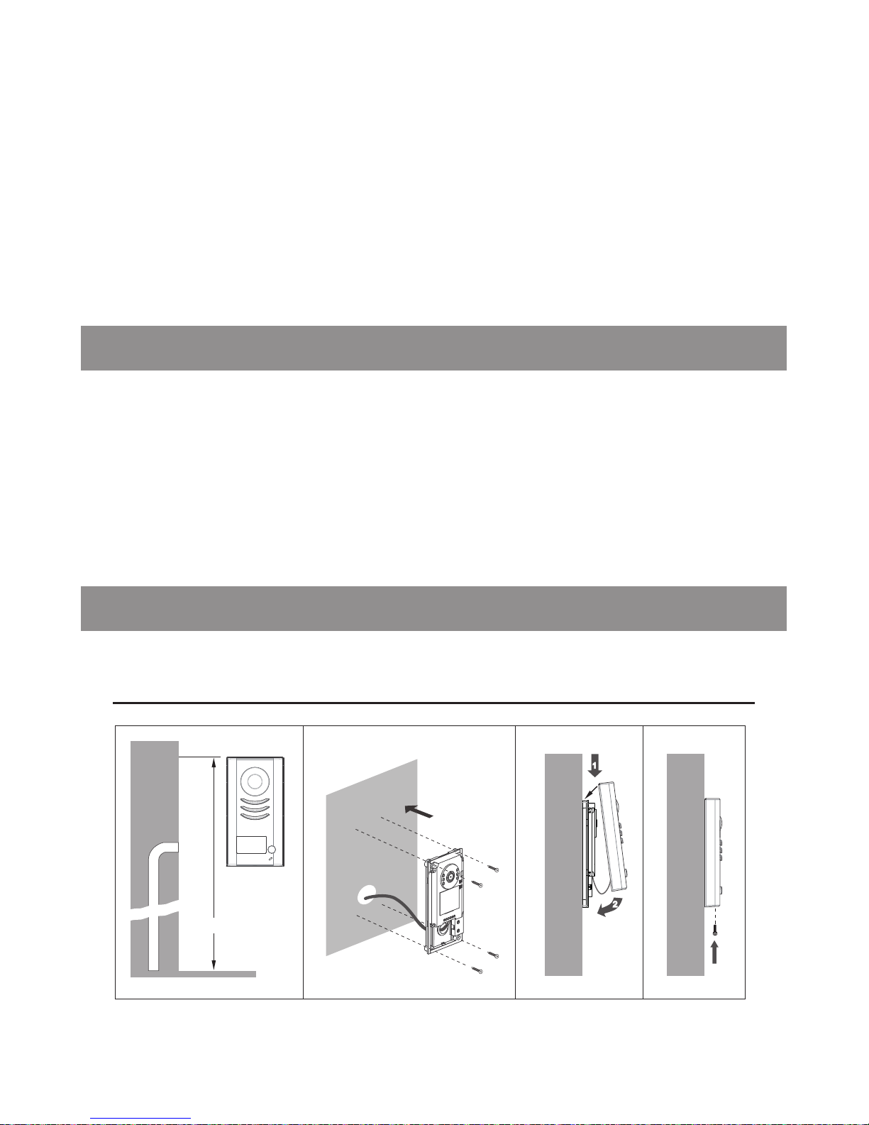
4.Mounting
4.1 Mounting Without Rainy Cover
160-165cm
1
2
1 2 3 4
Page 5
-3-
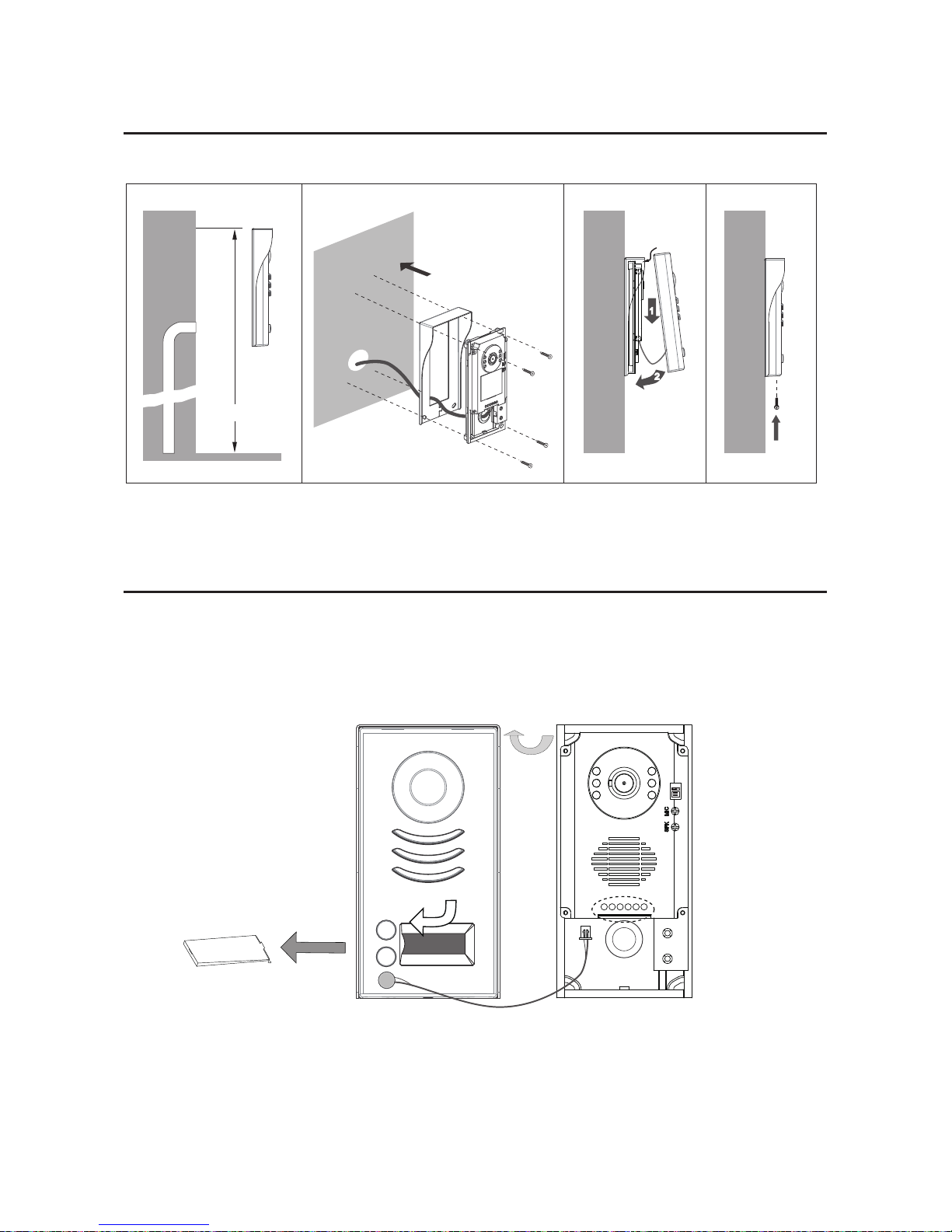
4.2 Mounting With Rainy Cover
160-165cm
1
2
1 2 3 4
4.3 Placing Name Label
Move the plastic cover away to open the transparent name label cover, insert a name paper, then put
the plastic cover back to the panel.
name label
12
ON
Page 6
-4-
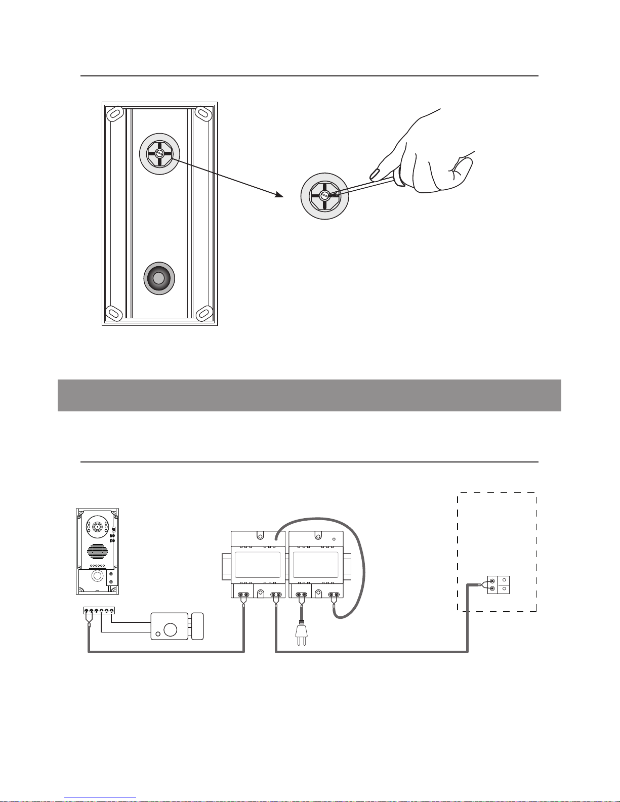
4.4 Adjusting Camera Angle
5.1 Basic Connection
use a screwdriver to loosen the screw and then adjust
the angle of the camera ,then x the screw.
5.System Wiring and Connections
-
+
AC~
monitor
PRODPS
PROPS4
12
ON
L1 L2 PL S1+ S2+ S-
Page 7
-5-
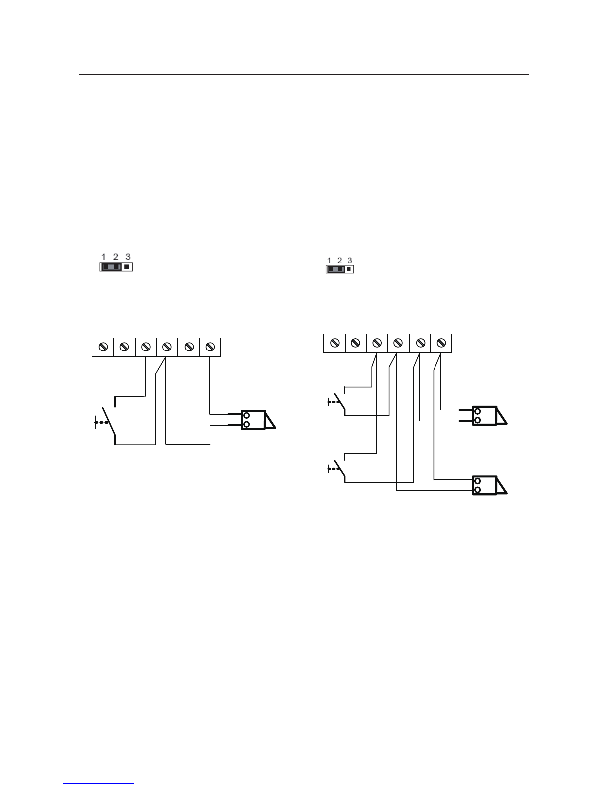
5.2 Electric Lock Connection
5.2.1 Door Lock Controlled with Internal Power
connect one lock connect two locks
Note:
1. Electronic lock of Power-on-to-unlock type should be used.
2. The door lock is limited to 12V, and holding current must be less than 250mA.
3. The door lock control is not timed from Exit Button(EB).
4. The
Unlock Mode
Parameter of Monitor must be set to 0 (by default).
EB
*
LOCK
BUS PL S1+ S2+ S -
LOCK
2
nd
1
ST
2
nd
EB
*
1
ST
Jumper position in
Connect two locks
1-2
EB
*
LOCK
BUS PL
S1+S2
+
S-
Jumper position in
Connect one lock
1-2
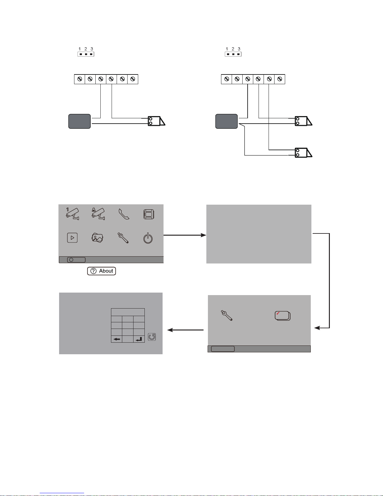
5.2.2 Door Lock Controlled with Dry Contact
Note:
1. The external power supply must be used according to the lock.
2. The jumper must be taken off before connecting.
3. Setup the
Unlock Mode
of Monitor for different lock types.
• Power-on-to-unlock type:Unlock Mode=0 (by default)
• Power-off-to-unlock type:Unlock Mode=1
Page 8
-6-
LOCK
BUS PL
S1+S2
+
S-
Take off the Jumper
POWER
SUPPLY
LOCK
BUS PL
S1+S2
+
S-
Take off the Jumper
POWER
SUPPLY
connect one lock connect two locks
5.2.3 Unlock parameter setting(set on monitor)
1.Touch item on main
menu page.
2.Touch the screen anywhere
and hold for 2s.
3.Touch Installer setup item
4.A digital keypad and setting
instructions will be shown.
Manual
Monitor
Monitor
Memory
Playback
Album
User Setup
09/30/2010 Thu.16:41
Close
Intercom
Multimedia
About
?
H/W : --- a1.3
S/W: V17.11.418.00
Local addr: --Unlock timing: --Video standard: UI-CODE: --MCM-VER.: --Updated: ---
Home
Installer
setup
Caliber
TouchScreen
Code Number:[----]
[0010]#:Remove all remote control
[0011]#:Add remote control
[8000]#:Set as master unit 0
[8001]#:Set as slaver unit 1
[8002]#:Set as slaver unit 2
[8003]#:Set as slaver unit 3
[8004]#:Set as guard unit
[8005]#:Set as not guard unit
[8006]#:Panel on as slaver unit called
[8007]#:Panel off as slaver unit called
[8008]#:Date format:MM/DD/YYYY
[8009]#:Date format:DD/MM/YYYY
[8010]#:Set lock mode to 0
[8011]#:Set lock mode to 1
[8021]~[8029]
#Set the lock time of 1~9s
Multi language settings:
---
1
4
7
8
0
9
6
5
2
3
Cancel
Installation settings:
Note:
1.must connect 352591/592 correctly before setting.
2.the parameter will be saved in 352591/592 automatically,so you need only set on one monitor.
3.the above diagram is t for icon menu series monitors only, to text menu series monitors,please
refer to the corresponding user manual.
Page 9
-7-
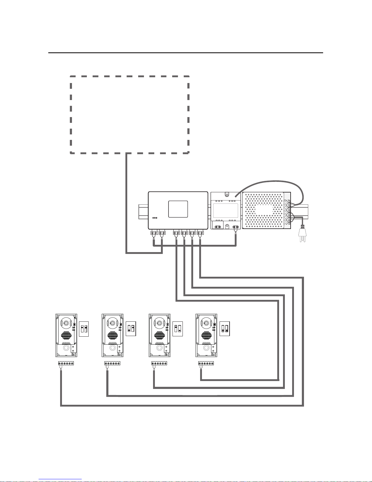
5.3 Multi Doorstations Connection
85~260VAC
PRODPS
PROS5
monitors
12
ON
L1 L2 PL S1+ S2+ S-
12
ON
L1 L2 PL S1+ S2+ S-
12
ON
L1 L2 PL S1+ S2+ S-
12
ON
L1 L2 PL S1+ S2+ S-
1 2
ON
1 2
ON
1 2
ON
1 2
ON
1# Camera
ID=00
ID=10
ID=01ID=11
2# Camera3# Camera4# Camera
352DBC4
A B C D
BUS
Page 10
-8-
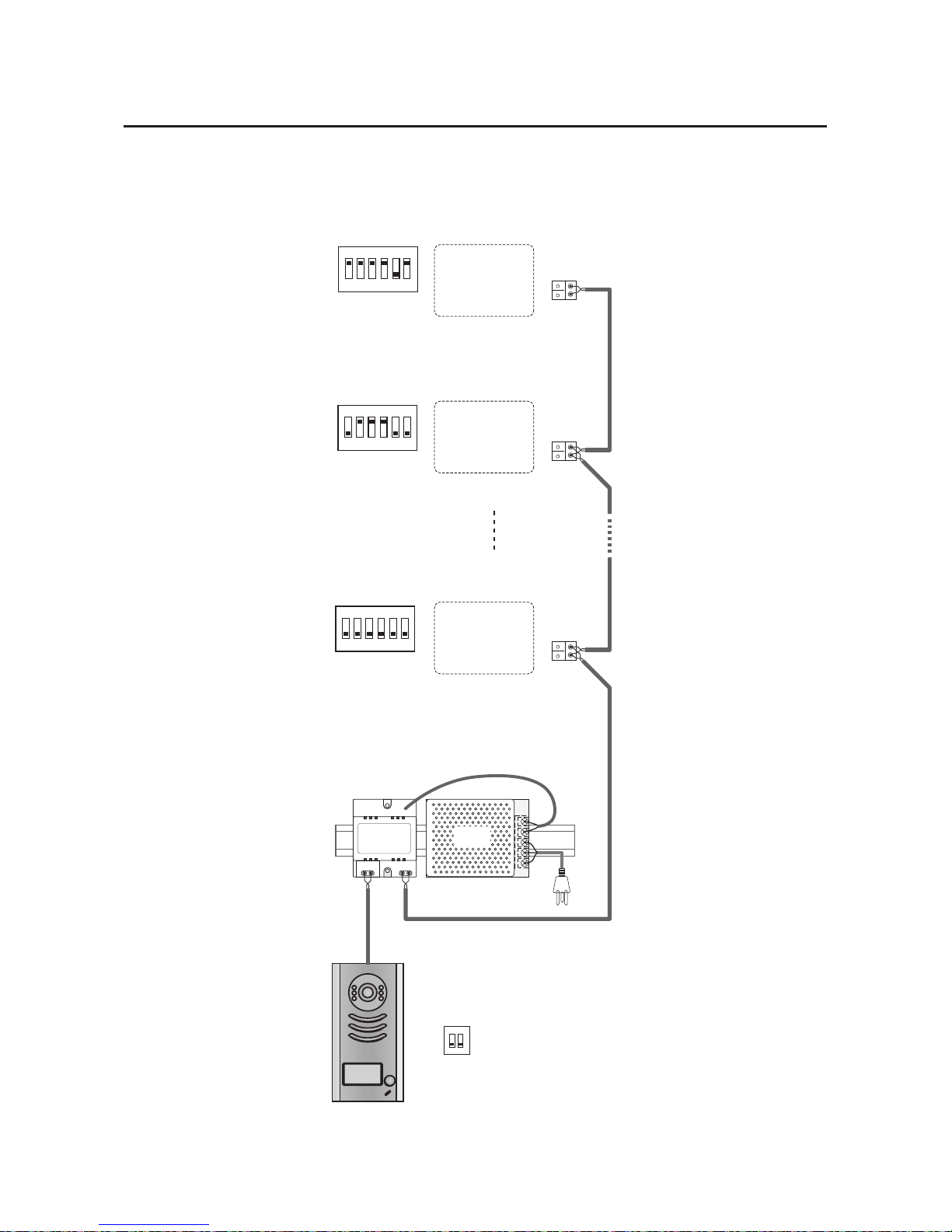
5.4.1 Basic IN-OUT Wiring Mode
5.4 Multi Monitors Connection
ID=00
1 2
ON
Code=0, DIP-6=off
Code=14, DIP-6=off
Code=15, DIP-6=on
1 2 3 4 5 6
ON
1 2 3 4 5 6
ON
1 2 3 4 5 6
ON
monitor
monitor
monitor
85~260AC
PRODPS
PROS5
Page 11
-9-
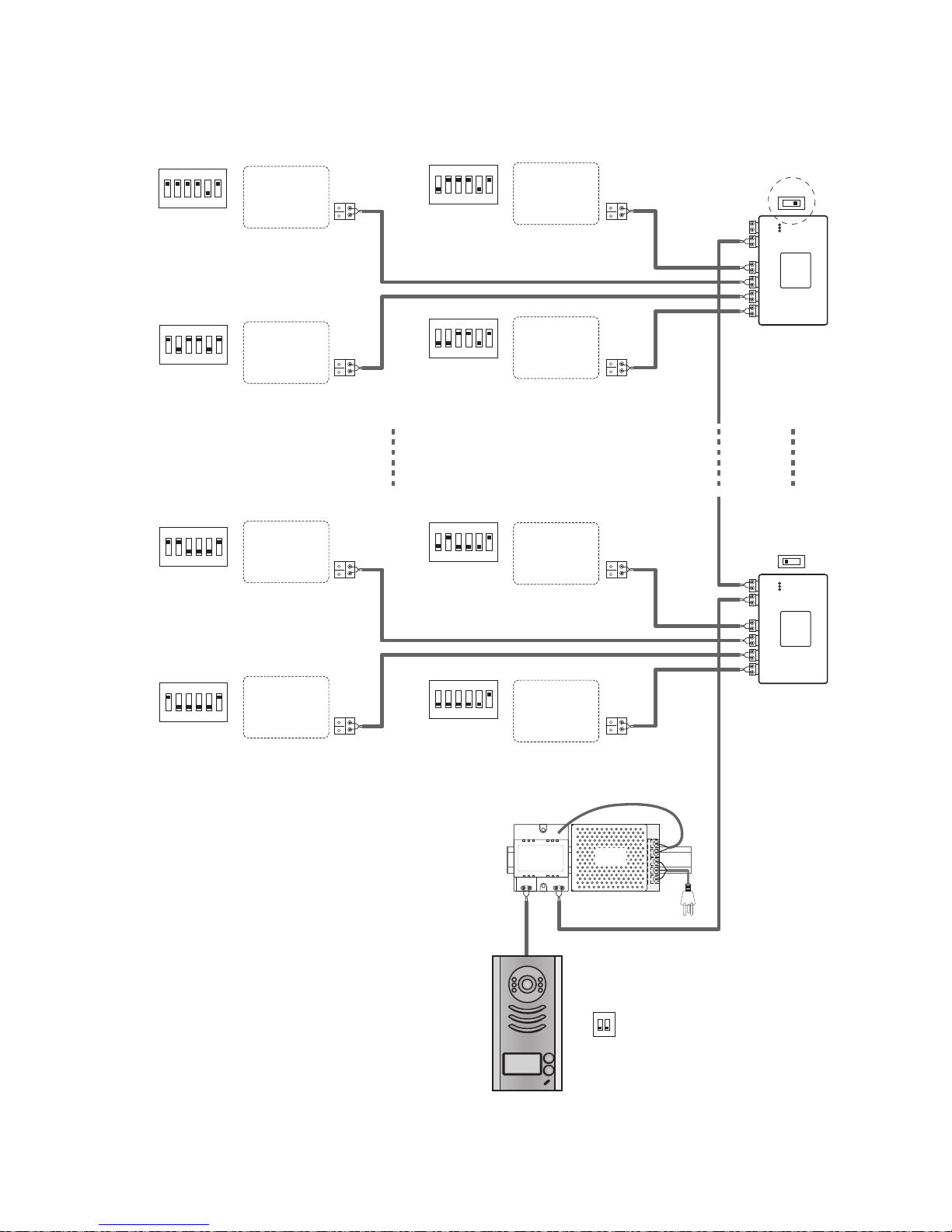
5.4.2 With PRODBC-4 Wiring Mode
HI
HI
monitor
monitor
monitor
monitor
monitor
monitor
monitor
monitor
352DBC-4
A B C D
IN
OUT
352'%C-4
A B C D
IN
OUT
85~260AC
PRODPS
PROS5
1 2 3 4 5 6
ON
1 2 3 4 5 6
ON
1 2 3 4 5 6
ON
1 2 3 4 5 6
ON
Code=15, DIP-6=on
Code=13, DIP-6=on
Code=3, DIP-6=on
Code=1, DIP-6=on
1 2 3 4 5 6
ON
1 2 3 4 5 6
ON
1 2 3 4 5 6
ON
1 2 3 4 5 6
ON
Code=14, DIP-6=on
Code=12, DIP-6=on
Code=2, DIP-6=on
Code=0, DIP-6=on
ID=00
1 2
ON
Page 12
-10-
6.Setup
6.2 DIP Switches Settings of Monitor
6.1 DIP Switches Settings of Doorstation
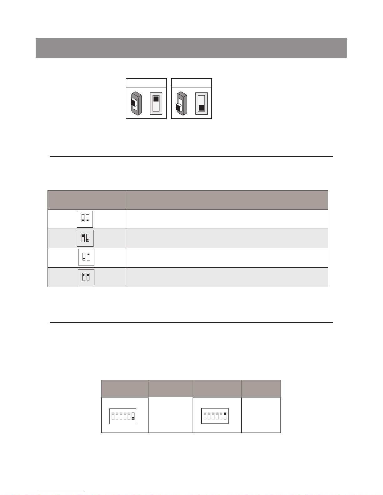
Total 2 bits on the DIP switches can be congured.The switches can be modied either before or after
installation.
Bit state Descriptions
Default setting, ID = 0(00), set to the rst Door Station.
ID = 1(10), set to the second Door Station.
ID = 2(01), set to the third Door Station.
ID = 3(11), set to the fourth Door Station.
1
2
ON
1 2
ON
1 2
ON
1 2
ON
There are 6 bit switches in total. The DIP switches are used to configure the User Code for each
Monitor.
ON(1)
=
OFF(0)
=
ON
ON
Bit-6 is used to set video impedance,it should be set to ON if the Monitor is in the end of the line(bus),
otherwise set to OFF.
Bit state Setting Bit state Setting
The monitor is
not at the end
of the bus.
The monitor
is at the end
of the bus.
1 2 3 4 5 6
ON
1 2 3 4 5 6
ON
Page 13
-11-
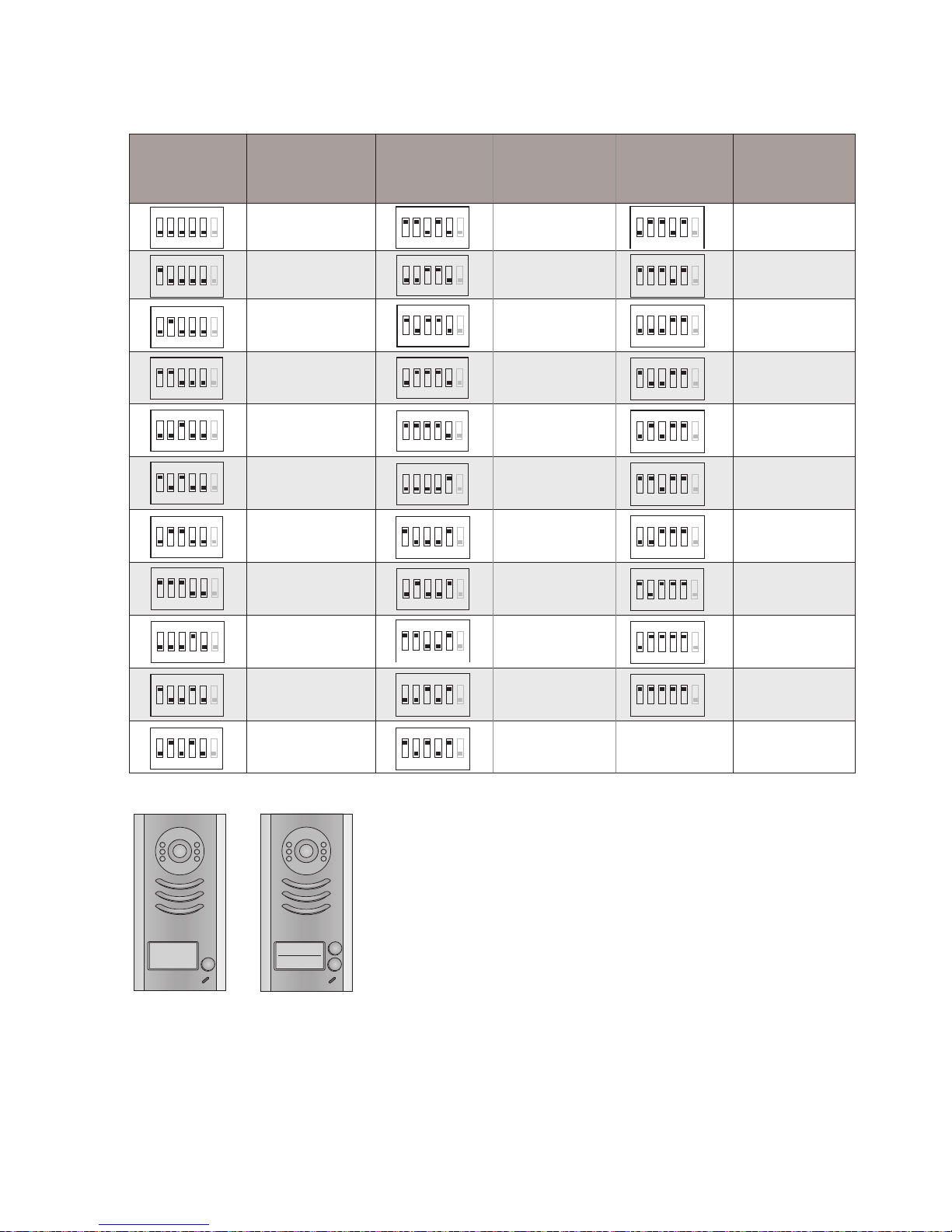
Bit state User Code Bit state User Code Bit state User Code
Code=0 Code=11 Code=22
Code=1 Code=12
1 2 3 4 5 6
ON
Code=23
Code=2 Code=13
1 2 3 4 5 6
ON
Code=24
Code=3 Code=14
1 2 3 4 5 6
ON
Code=25
Code=4 Code=15
1 2 3 4 5 6
ON
Code=26
Code=5 Code=16
1 2 3 4 5 6
ON
Code=27
Code=6 Code=17
1 2 3 4 5 6
ON
Code=28
Code=7 Code=18
1 2 3 4 5 6
ON
Code=29
Code=8 Code=19
1 2 3 4 5 6
ON
Code=30
Code=9 Code=20
1 2 3 4 5 6
ON
Code=31
Code=10 Code=21
Note:Monitors response button A must set the user code from 0
to 15.and button B set the user code from 16 to 31.
A
B
A
Bit-1 to Bit-5 are used to User Code setting. The value is from 0 to 31, which have 32 different codes .
1 2 3 4 5 6
ON
1 2 3 4 5 6
ON
1 2 3 4 5 6
ON
1 2 3 4 5 6
ON
1 2 3 4 5 6
ON
1 2 3 4 5 6
ON
1 2 3 4 5 6
ON
1 2 3 4 5 6
ON
1 2 3 4 5 6
ON
1 2 3 4 5 6
ON
1 2 3 4 5 6
ON
1 2 3 4 5 6
ON
1 2 3 4 5 6
ON
1 2 3 4 5 6
ON
1 2 3 4 5 6
ON
1 2 3 4 5 6
ON
1 2 3 4 5 6
ON
1 2 3 4 5 6
ON
1 2 3 4 5 6
ON
1 2 3 4 5 6
ON
1 2 3 4 5 6
ON
1 2 3 4 5 6
ON
1 2 3 4 5 6
ON
Page 14
-12-
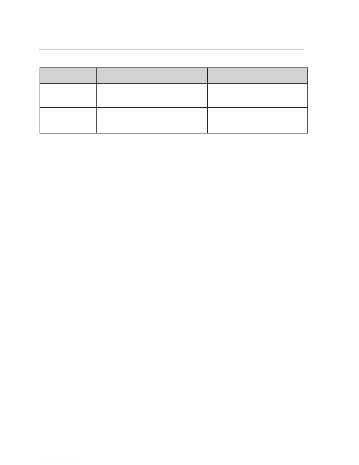
6.3 Notices
Name Discription Usage
P52S5-24V
Power supply,85~260Vac input,24Vdc/3A
output,10 DIN modules
Connect with multi doorstations or
multi monitors(up to 2 or above)
3526-24V
Power supply,85~260Vac input,24Vdc/1A
output,for basic kit only,4 DIN modules
Connect with one doorstation and one
monitor(35216 can be connected two)
Page 15
-13-
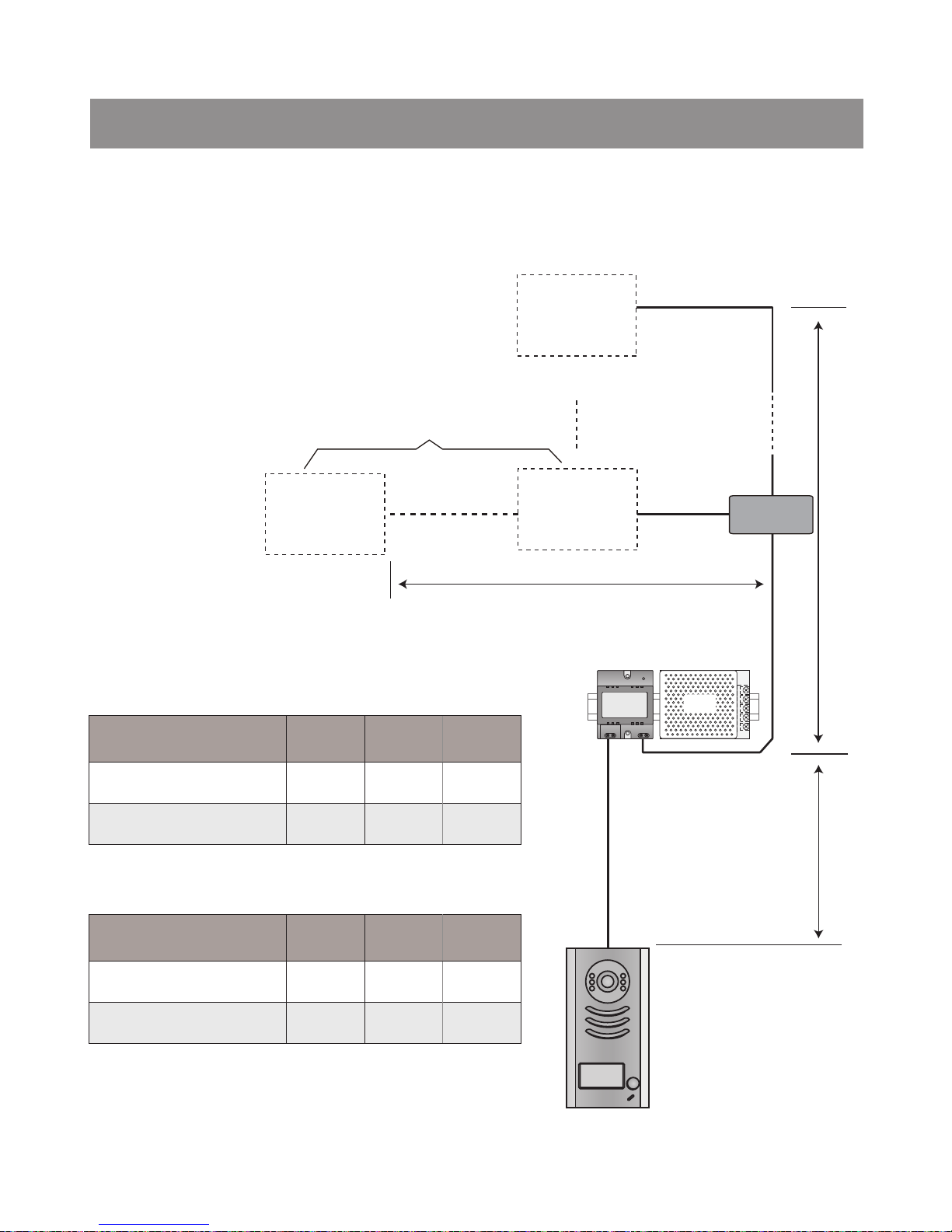
7.Cables Requirements
The maximum distance of the wiring is limited in the &KDOOHQJHU3UR system.
Using different cables may also affect the PD[LPXPGLVWDQFHZKLFKWKHV\VWHPFDQUHDFK
When Monitor quantity < 20
Cable Usage A B C
Twisted cable 2x0.75 mm
2
60 60 30
Twisted cable 2x1 mm
2
80 80 40
When Monitor quantity > 20
Cable Usage A B C
Twisted cable 2x1 mm
2
70 30 20
Twisted cable 2x1.5 mm
2
70 50 30
The farest monitor
B
A
C
PRODPS
PRODBC4
monitor
monitor
monitor
with two or four monitors
Note:If the monitor has been specied the distance,refer to the
parameter.
Page 16

The design and specications can be changed without notice to the user. Right to
interpret and copyright of this manual are preserved.
 Loading...