

Page 1

CHALLENGER PRO
2 WIRE - Video Intercom System
Technical Guide
Page 2

This techni
cal document is published for information purposes by
PROVISION SECURITY PRODUCTS
. In a policy of ongoing improvement,
PROVISION
SECURITY PRODUCTS
reserves the right to modify the contents of this document and the features of the products referred to herein at any time and
without
prior notice. Any such modifications shall be reflected in subsequent editions of this document
CONTENT
Section1 - Introduction 1
System Features
- - - - - - - - - - - - - - - - - - - - - - - - - - - - - - - - - - - - - - - - - - - - - - - - - - - - - - - - -
1
Home Applic at io ns
- - - - - - - - - - - - - - - - - - - - - - - - - - - - - - - - - - - - - - - - - - - - - - - - - - - - - - - -
2
Apartment Applications
- - - - - - - - - - - - - - - - - - - - - - - - - - - - - - - - - - - - - - - - - - - - - - - - - - - - - -
3
System Function
- - - - - - - - - - - - - - - - - - - - - - - - - - - - - - - - - - - - - - - - - - - - - - - - - - - - - -
4-5
Section2 - Units and Installations 6
Door Station
- - - - - - - - - - - - - - - - - - - - - - - - - - - - - - - - - -
6
Parts and f unctions
- - - - - - - - - - - - - - - - - - - - - - - - - - - - - - - - - - - - - - - - - - - - - - - - - - - - - - -
6
Place Name Plat e
- - - - - - - - - - - - - - - - - - - - - - - - - - - - - - - - - - - - - - - - - - - - - - - - - - - - - - - - 7
Adjusting Camera Angle
- - - - - - - - - - - - - - - - - - - - - - - - - - - - - - - - - - - - - - - - - - - - - - - - - - - - 7
Electronic Specifi cations
- - - - - - - - - - - - - - - - - - - - - - - - - - - - - - - - - - - - - - - - - - - - - - - - - - - -
7
Door Station Mounting
- - - - - - - - - - - - - - - - - - - - - - - - - - - - - - - - - - - - - - - - - - - - - - - - - - - - -
8
Terminal Descr iptions
- - - - - - - - - - - - - - - - - - - - - - - - - - - - - - - - - - - - - - - - - - - - - - - - - - - - - -
9
DIP user code settings
- - - - - - - - - - - - - - - - - - - - - - - - - - - - - - - - - - - - - - - - - - - - - - - - - - - - -
9
Door lock connection
- - - - - - - - - - - - - - - - - - - - - - - - - - - - - - - - - - - - - - - - - - - - - - - - - - - - - -
10-11
Monitor
- - - - - - - - - - - - - - - - - - - - - - - - - - - - - - - - - - - - -
12
Features
- - - - - - - - - - - - - - - - - - - - - - - - - - - - - - - - - - - - - - - - - - - - - - - - - - - - - - - - - - - - - -
12
Electronic Specifi cations
- - - - - - - - - - - - - - - - - - - - - - - - - - - - - - - - - - - - - - - - - - - - - - - - - - -
12
Terminal Descr iptions
- - - - - - - - - - - - - - - - - - - - - - - - - - - - - - - - - - - - - - - - - - - - - - - - - - - - -
13
Intercom function
- - - - - - - - - - - - - - - - - - - - - - - - - - - - - - - - - - - - - - - - - - - - - - - - - - - - - - - -
13
Color Pic ture Memory
- - - - - - - - - - - - - - - - - - - - - - - - - - - - - - - - - - - - - - - - - - - - - - - - - - - -
14
SD Card
- - - - - - - - - - - - - - - - - - - - - - - - - - - - - - - - - - - - - - - - - - - - - - - - - - - - - - - - - - - - - -
14
User Code Setup
- - - - - - - - - - - - - - - - - - - - - - - - - - - - - - - - - - - - - - - - - - - - - - - - - - - - - - - -
15
Monitor Exte nding Connect io n
- - - - - - - - - - - - - - - - - - - - - - - - - - - - - - - - - - - - - - - - - - - - - -
16
Accessories
- - - - - - - - - - - - - - - - - - - - - - - - - - - - - - - - - -
17
PRO-PS5 - Power Supply
- - - - - - - - - - - - - - - - - - - - - - - - - - - - - - - - - - - - - - - - - - - - - - - - - - - - - -
17
PRO-DPS
- - - - - - - - - - - - - - - - - - - - - - - - - - - - - - - - - - - - - - - - - - - - - - - - - - - - - - - - - - - - - - - - -
18
PRO-DBC
- - - - - - - - - - - - - - - - - - - - - - - - - - - - - - - - - - - - - - - - - - - - - - - - - - - - - - - - - - - - - - - - -
19
PRO-DBC -4 Unit
- - - - - - - - - - - - - - - - - - - - - - - - - - - - - - - - - - - - - - - - - - - - - - - - - - - - - - - - - - - -
20
Page 3

1
Section3 - Cables and Connections 24
General Rules for Installation
- - - - - - - - - - - - - - - - - - - - - -
24
Connecti ng the Co nn ec tor s
- - - - - - - - - - - - - - - - - - - - - - - - - - - - - - - - - - - - - - - - - - - - - - - -
24
Installation Heig ht
- - - - - - - - - - - - - - - - - - - - - - - - - - - - - - - - - - - - - - - - - - - - - - - - - - - - - - -
24
Door Station Install Condition
- - - - - - - - - - - - - - - - - - - - - - - - - - - - - - - - - - - - - - - - - - - - - - -
24
Table of Cables and D istance
- - - - - - - - - - - - - - - - - - - - - - - - - - - - - - - - - - - - - - - - - - - - - - -
25
System Wirings and Connections
- - - - - - - - - - - - - - - - - - -
26
1. Basic on e to one wiri ng and Cabl e Length
- - - - - - - - - - - - - - - - - - - - - - - - - - - - - - - - - - - -
26
2. Multi monitors IN -OUT wiring mode
- - - - - - - - - - - - - - - - - - - - - - - - - - - - - - - - - - - - - - - -
27
3. Multi m onitors St ar wiring mo de
- - - - - - - - - - - - - - - - - - - - - - - - - - - - - - - - - - - - - - - - - - - -
28
4. Multi Door Stations star wiring mode
- - - - - - - - - - - - - - - - - - - - - - - - - - - - - - - - - - - - - - - -
29
Section4 -System Setup 36
What’s User Code
- - - - - - - - - - - - - - - - - - - - - - - - - - - - - - - - - - - - - - - - - - - - - - - - - - - - - - -
36
What's Slave Address
- - - - - - - - - - - - - - - - - - - - - - - - - - - - - - - - - - - - - - - - - - - - - - - - - - - -
36
Installation setup on monitor
- - - - - - - - - - - - - - - - - - - - - - - - - - - - - - - - - - - - - - - - - - - - - - - -
37
Shortcut for touch sc reen calibration of monitor
- - - - - - - - - - - - - - - - - - - - - - - - - - - - - - - - - -
39
Page 4
Section1 - Introduction
System Features
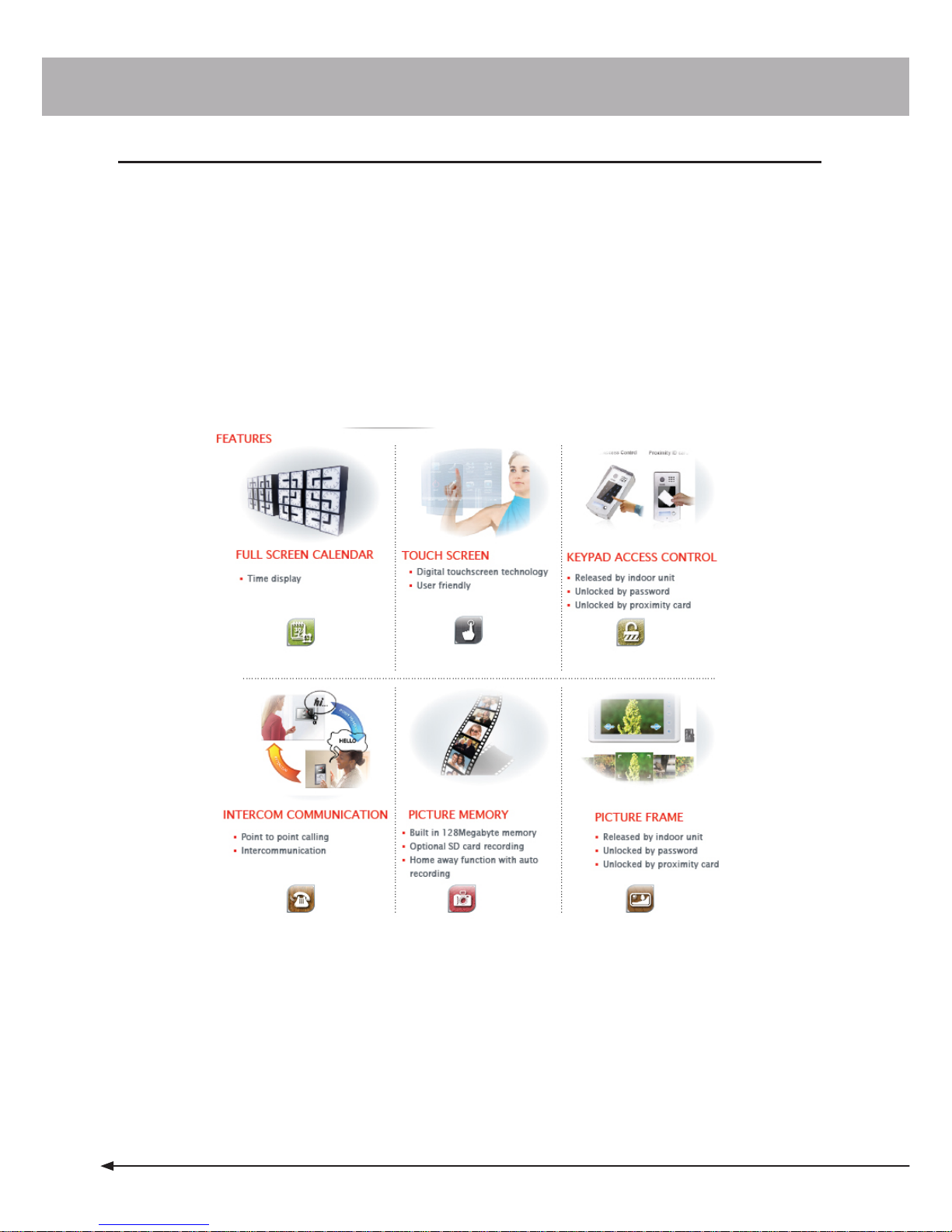
• The Provisi on Challenger Pro 2 wire s ystem can be easily installed in simple domestic home installations or
complex apartment installations with up to 4 entrances. The best feature about C hallenger P ro is that all
products in the range are compatible and configurable to suit almost a ny installation requirement
• Provision Challenger Pro offers a vari ety of door s tations to suit the fus siest of c ustomers. Choose from the
super slim wall/desktop mounted 3.5” PRO16 through to the 1 0” PRO21 all with col orful interf ace and touch
screen operation. Where required Pi cture mem ory option is available with PR O 27, PRO692, PRO10, and
PRO25 moni tors
• Choose fr om a variety of door s tations ranging from a basic 1 but ton model up to code keypad or card reader
with all in one design s tyles. Adjustable camera an d IP67 full s tainless steel const ruction are standard
features across the Provision Challenger Pro door station r ange.
Page 5
1
Home Applications
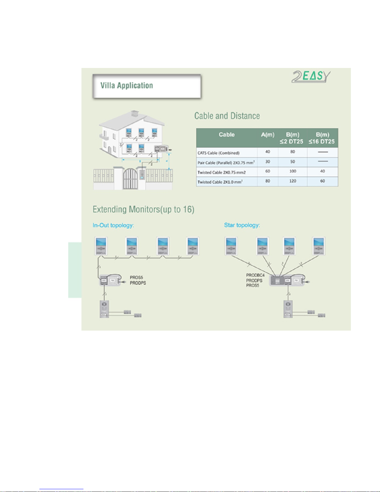
Supports up to 16 monit ors and 4 door st ati ons. 2 l ock are also supported at each entrance
Page 6
Apartment Applications
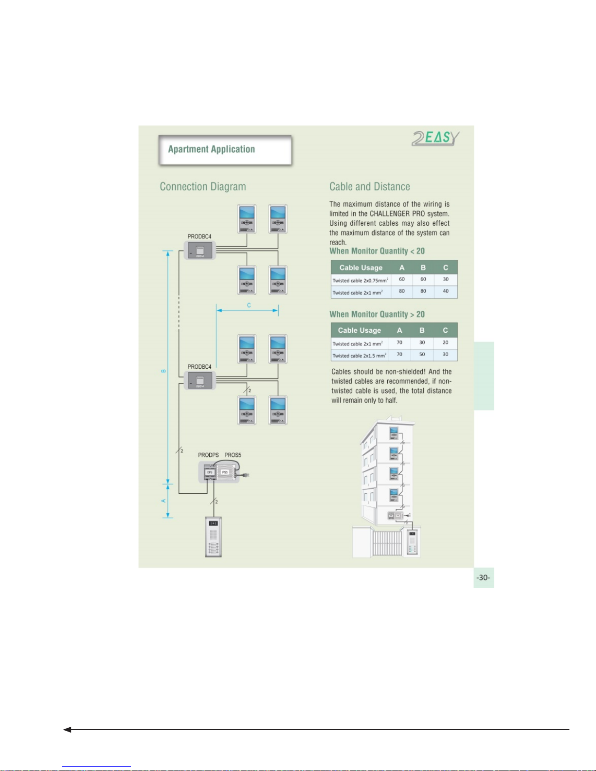
Supports up to 32 monitors and 4 door stat ions . 1 lock is also supported at each entrance
Page 7

1
System Function
Internal monitor station
۞ Full range line 3.5’’/4’’/5’’/7’’/10’’ digital TFT;
۞ Super slim design with surface mounting;
۞ Touch screen operation with friendly interface;
۞ Intercom by name list and selective int er com;
۞ Selective monitoring each door stations or CCTV cameras;
۞ Inner 128M flash picture memory and extended SD card recording (
SD card not supplied);
۞ Digital Photo Frame function;
۞ Wall & Desktop installation;
۞ 12 melody options;
۞ Mute function
Page 8

PRO - System - Technical Guide
2
Door station
۞ Metal housing (Aluminium/Zinc –Alloy/ Stainless steel options-all IP66 weather rated);
۞ High resolution adjustable camera (CCD, ARS camera);
۞ Two independent relays for two locks control;
۞ Code lock control & Proximity access control
۞ Name plate display;
۞ Camera adjustable ;
۞ Night
-
view;
Additional features:
۞ Calling from door station;
۞ Dual communication with external unit;
۞ Dual intercom communi cati on between indoor units;
۞ Unlock during calling, conversation, monitoring;
۞ Two locks for separate control;
۞ Picture capture and continuous ph oto shoo tin g, Ho me
-
away function of auto -recording;
Digital Photo Frame function (limited to PRO27, PRO692, PRO10, and PRO25
monitors supporting SD card) ;
۞ Multi languages choosing & SD card languag es upgra din g;
Page 9

Page 10
4
176
mm
Section2 - Units and Installations
Door Station
Features
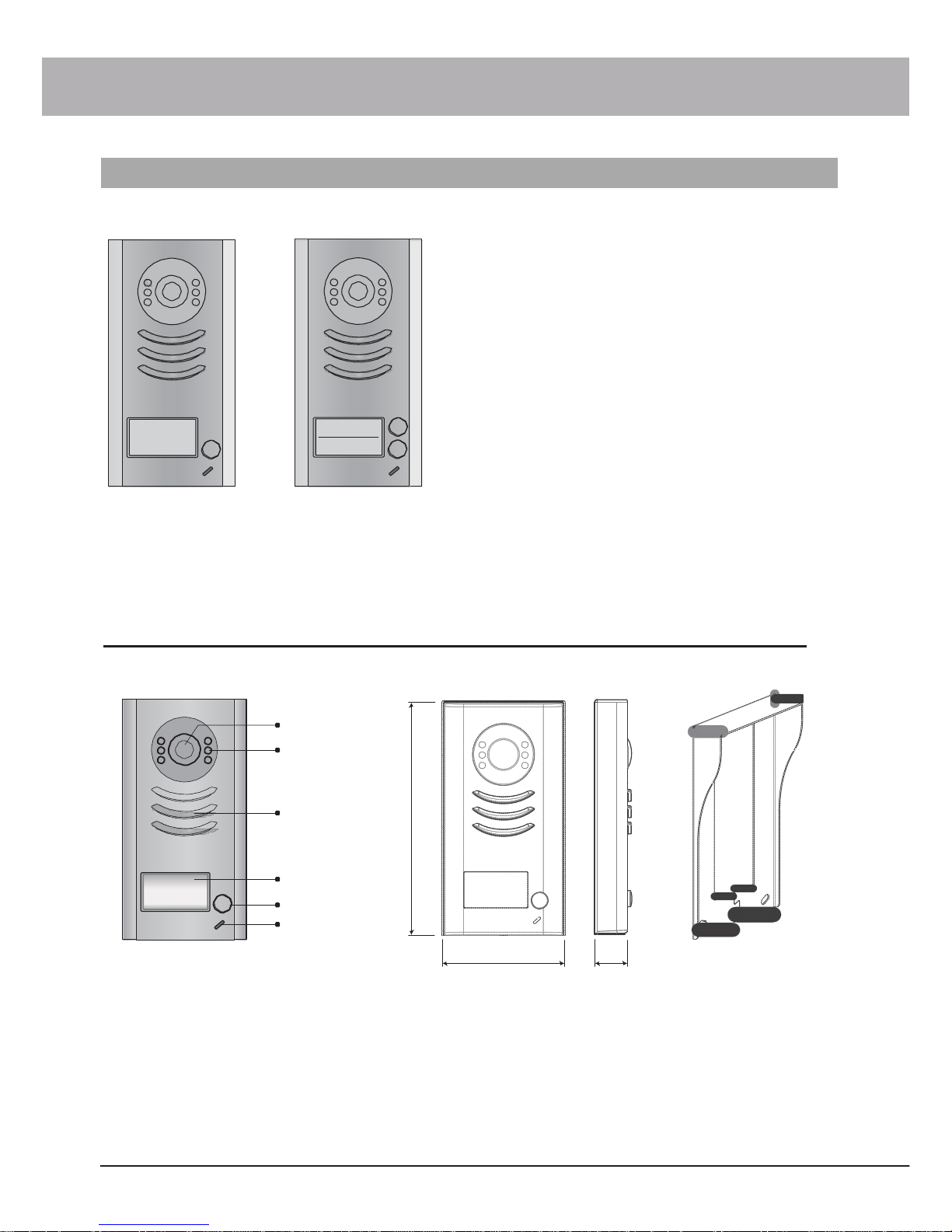
• Full zinc alloy panel.
• Pin
-
hole color CC D camera.
• Camera angle adjusta ble.
• Night
-
view LED.
• Backlight name plate.
• DIP switches for mul ti door st ation conf iguration.
• Direct connect to electroni c lock of 12Vdc.
• Exit button.
• Plug
-
in connect or to connect bus line.
PRO591 PRO592
Parts and functions
Camera
Lens
Night View
LED
Speaker
Nameplate
Call
Button
Microphone
Rainy Cover
90 mm
23 mm
Page 11
PRO - System - Technical Guide
5
ON
1 2
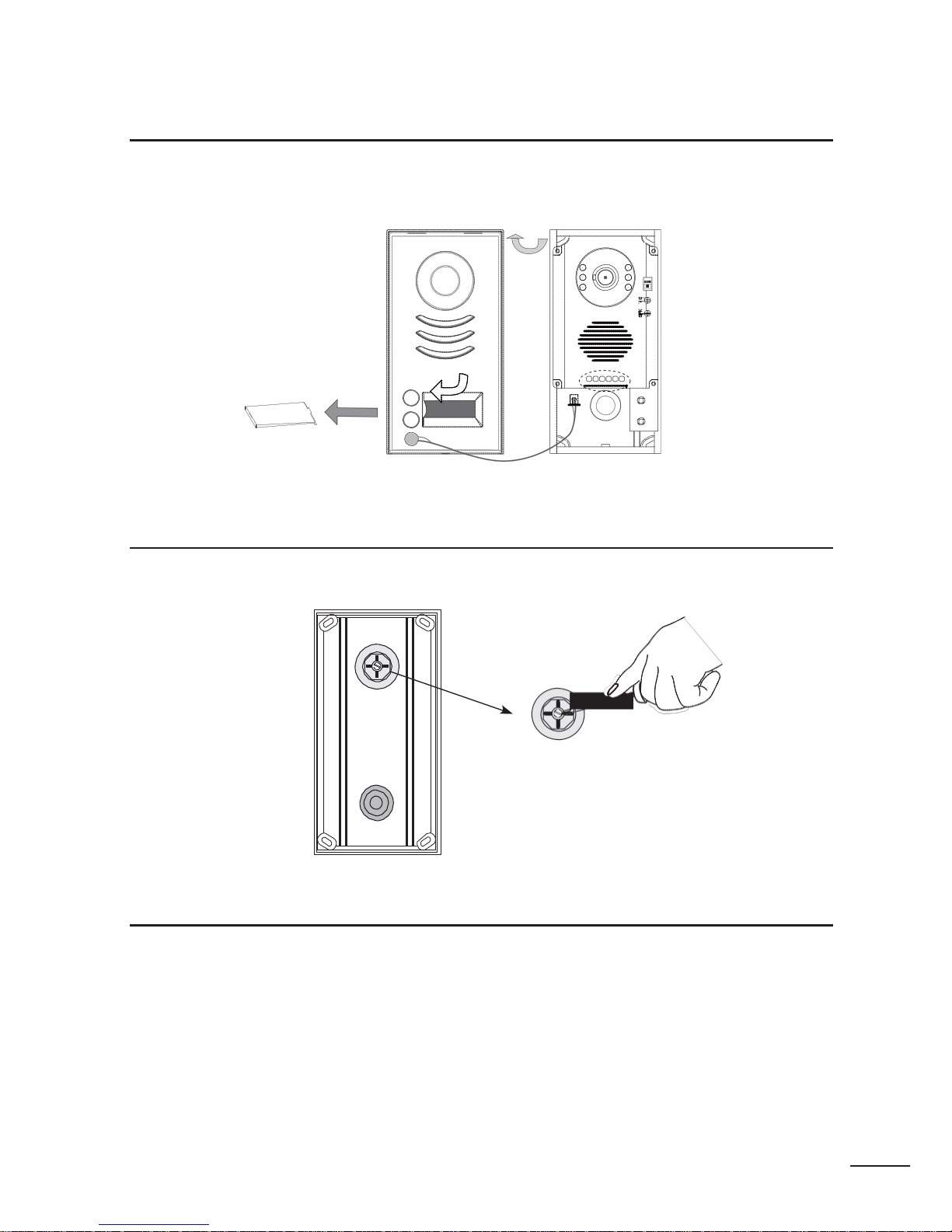
Place Name Plate
Move the plastic cover away to open the transparent name label cover, insert a name paper, then put the plastic
cover back to the pan el.
name
label
Adjusting Camera Angle
Use a screwdriver to loosen the screw and t hen adjust the angle of the camera, then fix the screw.
Electronic Specifications
Power Supply : DC 24V (supplied by PROS4
-
24V or PROS5-24V);
Power Consumption: Standby 50mA; Working status 200mA;
Camera: Pinhole Sharp Color CCD; 42 0 TV Lines;
Unlocki ng time: 1
-
9S, set by moni tor;
Talking Time: 90S;
Lock Power supply: 12Vdc, 300mA(Inter nal Power);
Working Temperature: -10
0
C~+450C;
Dimension: 176(H)×90(W)×24(D)mm
Page 12
6
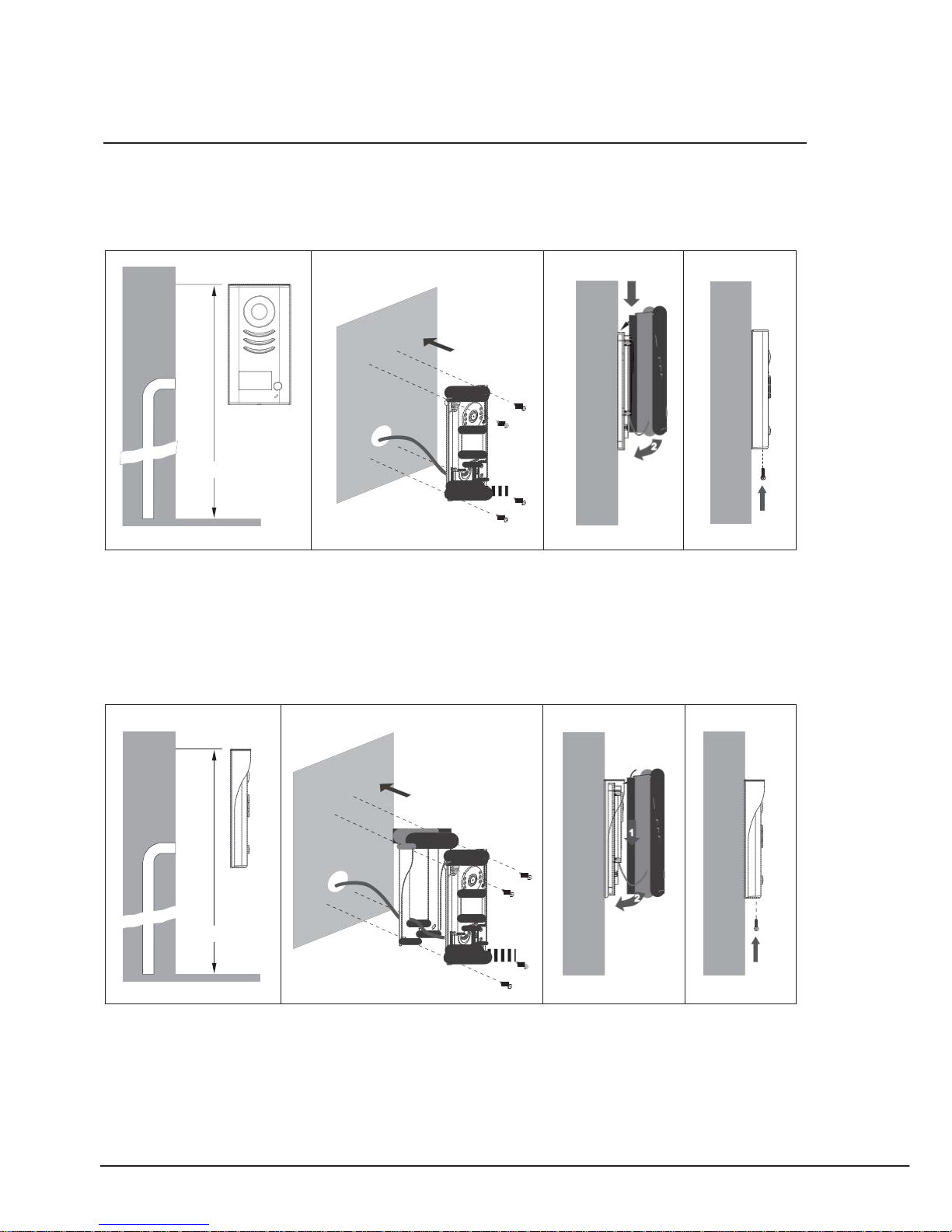
Door Station Mounting
Mounting Without Rainy Cover
1
160-165cm
2 3
1
2
4
Mounting With Rainy Cover
1
160-165cm
2
3
1
2
4
Page 13
PRO - System - Technical Guide
7
ON
1 2
ON
1 2
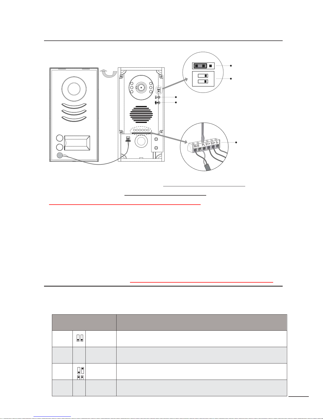
Terminal Descriptions
1 2 3
Lock Control
Jumper
Doorstation Code
DIP
MIC
adjustment
SPK
adjustment
Main Connect
Port
•
Lock Control Jumper:
To select the lock type: see door lock connection section
•
Door station Code DIP:
Total 4 door stations can be supported
DIP SWITCHES IN OFF POSITION ON SINGLE DOOR SYSTEM
•
Main Connect Port:
To connect the bus line and the electronic locks.
• BUS: Connect to the bus line, no polarity.
• PL: External lock power input, connect to the power positive(power +)
• S1+, S2+: Lock power(+) output, to connect 2 locks.
• S
-
: Lock power( -) output, connect to the power( -) input of locks(only when using the camera to
power the locks, if using the external power supply for the locks, the S
-
will not be connected).
DIP user code settings – ONLY APPLICABLE FOR MULTI DOOR STATION
Total 2 bits on the DIP switches can be configured. The switches can be modified either before or after
installation.
Bit state
Descriptions
ON
1 2
Default setting, ID = 0(00), set to the first Door Station.
ON
1 2
ID = 1(10), set to the second Door S tation.
ON
1 2
ID = 2(01), set to the third Door Station.
ON
1 2
ID = 3(11), set to the fourth Door Station.
Page 14
8
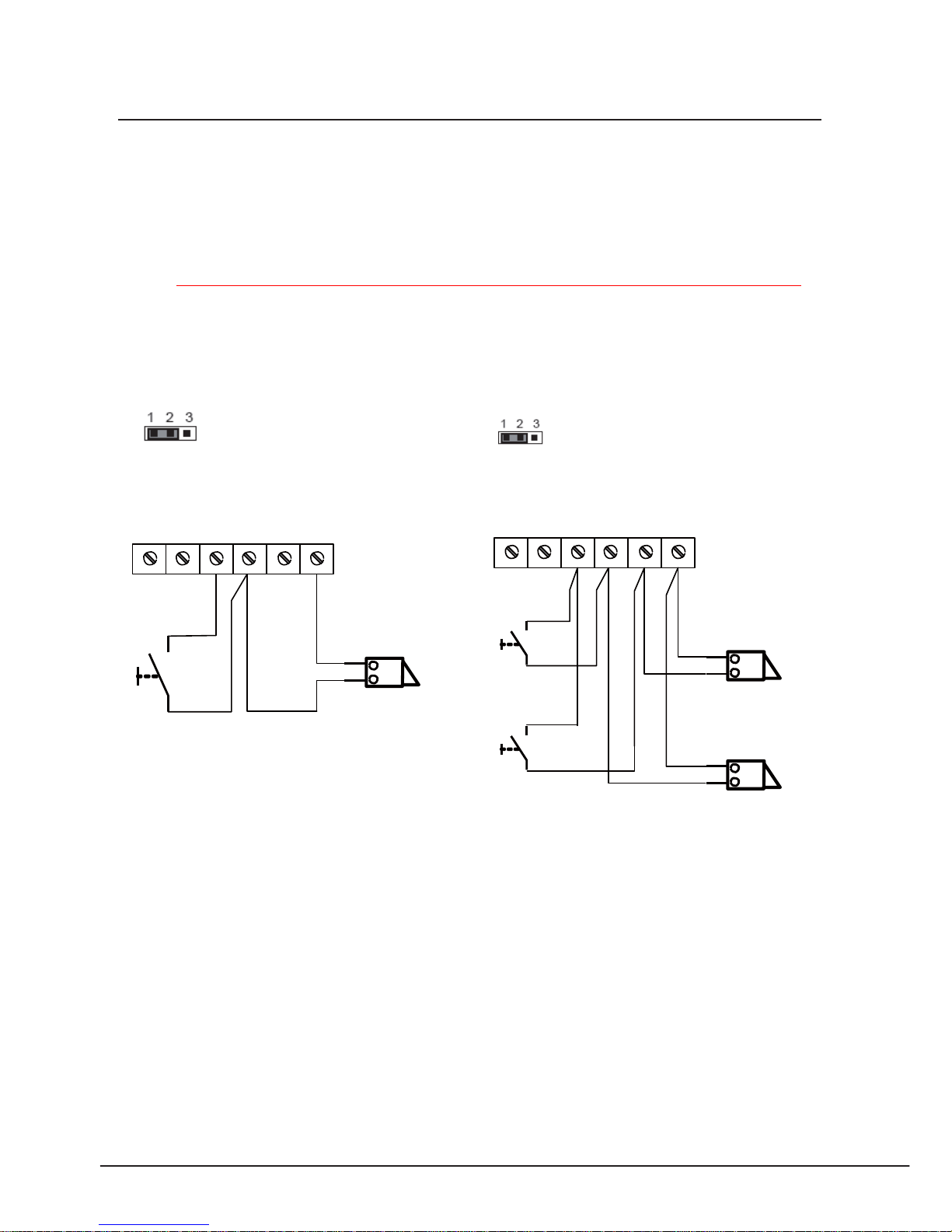
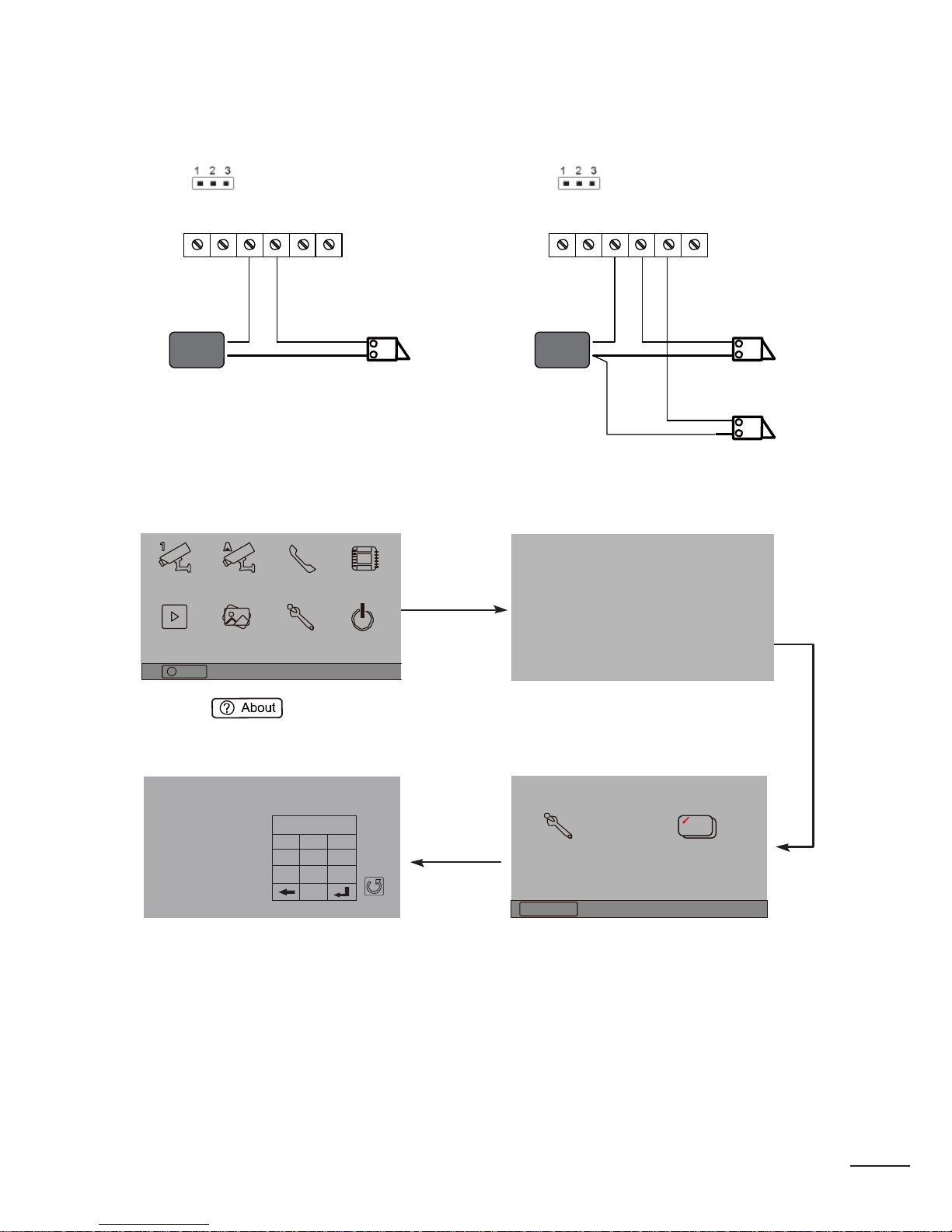
Door lock connection
Door Lock Controlled with Inter na l Po wer
Note:
1. Electronic lock of Power -on -to -unlock type should be used.
2. The door lock is limited to 12V, and holding current must be less than 250mA.
3. The door lock control is not timed from Exit Button(EB).
4. The
Unlock Mode
Parameter of Monitor must be set to 0 (by default).
Connect one lock Connect two locks
Connect one lock
Connect two locks
Jumper position in 1-2
Jumper position in 1-2
BUS PL
S1
+
S 2
+
S-
BUS PL S1+ S2+ S -
*
EB
LOCK
*EB
*
EB
2
nd
1
ST
LOCK
2
nd
1
ST
LOCK
Door Lock Controlled with Dry Contact
Note:
1. The external power supply must be used according to the lock.
2. The jumper must be taken off before connecting.
3. Setup the
Unlock Mode
of Monitor for different lock types.
• Power -on -to -unlock type:Unlock Mode=0 (by default)
• Power -off -to -unlock type:Unlock Mode=1
Page 15
PRO - System - Technical Guide
9
Code Number:[----]
1 2 3
4
5
6
7
8
9
0
Connect one lock Connect two locks
Take off the Jumper
Take off the Jumper
BUS PL
S1 S2
S-
+ +
BUS PL
S1 S 2
S-
+ +
POWER
SUPPLY
LOCK
POWER
SUPPLY
LOCK
Unlock parameter setting(set on monitor)
Manual
Monitor
Monitor
Intercom Multimedia
H/W : --- a1.3
S/W: V17.11.418.00
Local addr: --Unlock timing: --Video standard: -
Memory
Playback
Album
User Setup Close
UI-CODE: --MCM-VER.: ---
? About
09/30/2010 Thu.16:41
Updated: ---
1.Touch item on main
menu page.
2.Touch the screen anywhere
and hold for 2s.
Installation settings:
[0010]#:Remove all remote control
[0011]#:Add remote control
[8000]#:Set as master unit 0
[8001]#:Set as slaver unit 1
[8002]#:Set as slaver unit 2
[8003]#:Set as slaver unit 3
[8004]#:Set as guard unit
[8005]#:Set as not guard unit
[8006]#:Panel on as slaver unit called
[8007]#:Panel off as slaver unit called
[8008]#:Date format:MM/DD/YYYY
[8009]#:Date format:DD/MM/YYYY
[8010]#:Set lock mode to 0 [8011]#:Set
lock mode to 1
[8021]~[8029]
#Set the lock time of 1~9s
Multi language settings:
---
Cancel
Installer
setup
Home
Caliber
TouchScreen
4.A digital keypad and settin g
instructions will be shown.
3.Touch Installer setup item
Note:
1. Must connect PRO591/592 correctly before setting.
2. The parameter will be saved in PRO591/592 autom ati cal l y ,so you need only set on one moni
-
tor.
Page 16
10
BT1
BT2
EH
GND
VD
Monitor
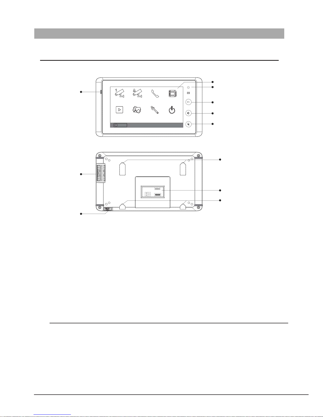
Features
Microphone
Screen
Indicator
Manual
Monitor
Monitor
Intercom Multimedia
UNLOCK Button
Memory
Playback
Album User Setup
Close
TALK/MON Button
?
About
09/30/2010 Thu.16:41
MENU Button
Speaker
Mounting Hook
L1
ON
DIPS
Connection Port
SD card slot
L2
1 2 3 4 5 6
Mounting Hook
• Touch screen operation.
• Picture memory optional.
• Using DIP for Monitor ID setting.
• Using plug
-
in connect or.
• On screen name list for intercom.
• No additional power supply needed(supplied by system).
• Additional door bell call button
• External ringer connection
*NB- red /black wire = ringer
White/green wire = doorbell
Black/ yellow wire = TV out
Electronic Specifications
Power supply: 24Vdc(supplied by PRODPS)
Power Consumption: Standby 15mA; Working st atus 400m A
Monitor Screen: 7 Inch color TFT
-
LCD
Display Resolution: 800*3(RGB)*480 pixels
Dimension: 125(H)×225(W)×23(D)mm
Page 17
PRO - System - Technical Guide
11
BT1
BT2 EH
GND
VD
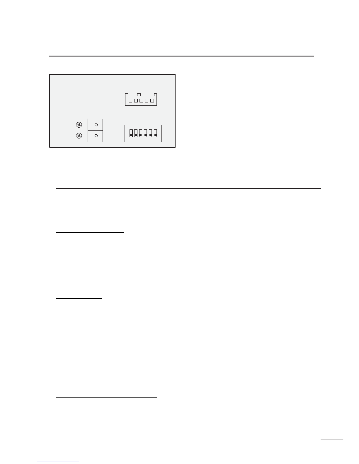
Terminal Descriptions
Monitor
Connection Board
L1
L2
DIPS
ON
•
SW+:
Door bell call button.
•
SW-:
Door bell call button.
•
EXT-RING:
External ringer out put(12Vdc 100mA)
•
GND:
Ground.
•
VIDEO:
Video signal output.
• S1: DIP switches for system configurations
• BUS: non polarity bus line
.
1 2 3 4 5 6
.
Intercom function
There are three kinds of intercom function available in the Challenger PRO system.
1. Guard Unit Call
A Monitor can be assigned to be the guard unit Monitor, by setting on the OSD screen of the Monitor. When the
user's Monitor is in standby, press call button or intercom button, the intercom page will show up on the screen, then
select and confirm 'Call Guard Unit' item, and the Monitor will call the guard unit Monitor, when the guard unit Monitor
answers the call, conversation with the guard person is started. Please refer to section 4
-
>system setup ->installation
setup
-
>how to set the monitor as a guard unit.
2. Inner Call
For multi m onitor installs Intercommunication between monitors can b e achieved via:
Press MENU
INTERCOM ICON OR INN ER CALL (BY NAME LIST)
When using name list f unction, s elect addres s and press ‘DIAL NUM BER ICON’
When the Monit or is in standby, press call button or intercom button, the intercom page will show up on the screen,
than select and confirm 'Inner Call' item, and other Monitors will ring at the same time. When any Monitor answers
the call, other Monitors will s top ringing and go bac k to standby state.
3. Intercom Call (Name lis t)
The name list intercom is for room to room calling. The user in one room can call other rooms by selecting the name
on the scr een. In this way, it's no need to r emember th e user code of the other users.
Page 18

12
Color Picture Memory
The monitors have been equipped with a built -in memory (about 120 MB) together with a SD card reader. An SD card up to
16 GB (Maximum) is supported
. User can both record the pictures manually and set the Monitor to automatic all y recor d pic tur es .
• Manually record: when the Monitor is in monitoring or talking state (the screen is turned on), press the capture
icon on the touch screen, the captured pictures will be saved in a folder named by date and will be saved into
the built
-
in flash memory of the Monitor.
• Automatically record: pictures will be saved after 3 seconds when the visitor pressed the call button on the Door
Station.
• The captured pictures in the built
-
in memory can be copied to the SD card, and you should use T -views memo
software tool to convert the pictures to JPG format that can be seen on the computer. (select the pictures(press
Ctrl+A to select all)
-
>>click the right key of the mouse ->>choose transfer selected to JPG item ->>save the pic
-
tures on co mputer)
• When the built
-
in memory is full,t he oldest picture will be deleted to make room for new record .
• The built
-
in memory can be formatted by the M onitor.
SD Card
Built -in SD card r eader, maximum 16 GB suppor ted.
• Photo frame function, each photo playing will last 5 seconds, More pictures in the SD card, longer time for trig
gering the function, 800 pictures is supported in inner memory. With 2G SD card more than 30000 pictures can
be support ed.
• Must use T
-
views album software tool to transform the JPG format photos taken by digital camera to TVS format
photos th at can be viewed on Monitor.
• Photos can be played both manually and automatically, use your fingers to slide right or left on screen to play
last/next photo.
• The SD card cannot be formatted on monit or directly ,you should f ormat the SD card on a computer.
• Avoid plugging in/out the SD card w hen the mo nitor is under operation.
• Playing will be interrupted by the call ing from outdoor station.
Page 19
PRO - System - Technical Guide
13
Code
Number:[-- --]
1 2 3
4
5
6
7 8
9
0
PROGRAMMING
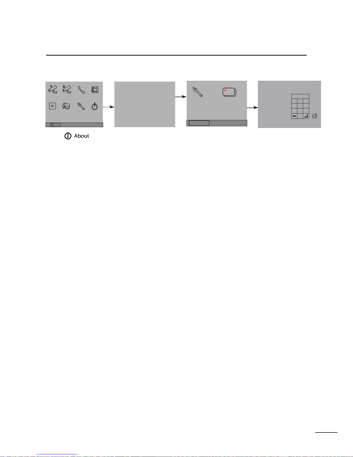
How to enter the installation setting page
Manual
Monitor
Monitor Intercom Multimedia
H/W : -- a1.3
S/W: --Local add r: --Unlock timing: --Video standard: -
Installer
setup
Caliber
TouchScreen
Installation settings:
[0010]#:R emove
all
remote co ntrol
[0011]#:A dd remote co ntrol
[8000]#:S et
as
master
unit
0
[8001]#:S et
as
slaver
unit
1
[8002]#:S et
as
slaver
unit
2
[8003]#:S et
as
slaver
unit
3
[8004]#:S et
as guard
unit
[8005]#:S et
as not guard
unit
[8006]#:P anel
on as
slaver
unit
called
[8007]#:P anel
off as
slaver
unit
called
[8008]#:D ate format:MM/DD/YYYY
[8009]#:D ate format:DD/MM/YYYY
[8010]#:S et
lock mode to
0 [8011]#:S et
lock mode to 1
Memory Album
User Setup Close
Playback
UI-CODE: --MCM-VER.: --Updated: ---
Home
[8021]~[80 29]
#Set the lock time of
1~9s
Multi
language settings:
---
Cancel
?
About
09/30/2010 Thu.16:41
1.Touch item
on main menu page.
2.Touch the screen any
-
where and hold for 2s .
3.Touch Installer setup
item
4.A digital keypad and in
-
structions will be sh owed.
Page 20
14
How to set the slave monitor address
Maximum 4 monitors can be connected in one apartment, one master monitor together with 3 slave monitors, so you
should set the address correctly.(note :must have one monitor to b e set as master monitor)
The code of 8000 # is used to set th e master m onitor.
The code of 8001 # is used to set the first slave monitor . The c ode of 8002# is
used to set the second slave monitor . The c ode of 8003# is used to set the
third slave monitor .
Entry of ALL digits is required, for example 8008 is ent ered as 8 0 0 8 #
Note :touch # to save t he settings (MARK ED AS ENTER IN DIAGRAM) and * button to cancel the in p ut, touch (M ARKED AS
BACK SPACE IN DIAGRAM)
How to set date and time format
The system offers two methods of date and tim e
8009# is used to set the date format as date/month/year.
8008# is used to set t he date format as month/date/year.
8012# is used to set t he time format as 12 hour system
8013# is us ed to set the t ime format as 24 hour system
How to set the monitor panel on
8006# is used to set the slave monitor as simultaneous display . This is required to be entered into EACH SLAVE
monitor for simultaneous answer.
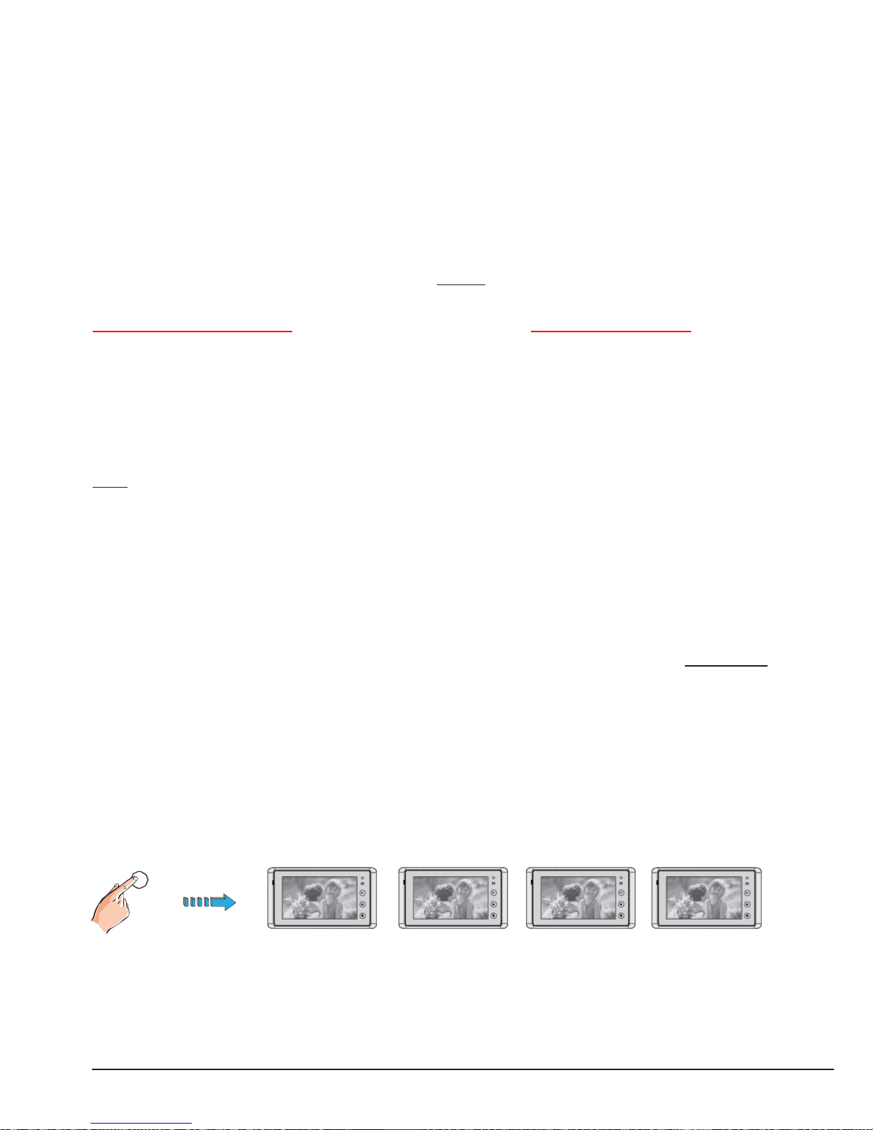
In default mode, when receiving a call, the master and slave monitors will ring at the same time, and just the master
monitor can display the image while the slave monitors cannot. The settings can be changed, you can set the master
monitor and all the slave monitors to panel on at the same time when receiving a call, just input the code number of 8006
on each slave monitor.
Press cal l button When receiving calling, all monitors can display the image at t he same time
on door station
Page 21
PRO - System - Technical Guide
15
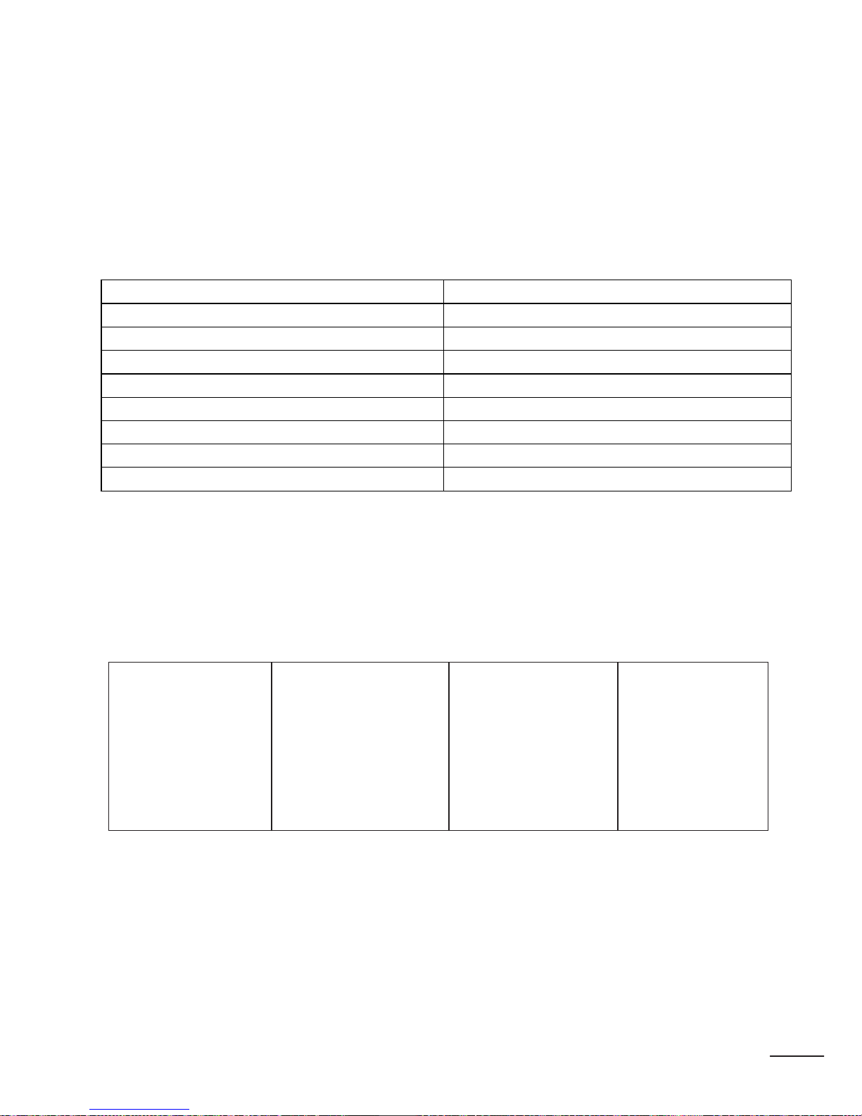
How to set the unlock paramet er
UNLOCK MODE: :
8010# is used to set the unlock mode to 0 (POWER TO UNLOCK FAIL SECURE)
8011# is used to set the unlock mode to 1 (POWE R TO LOCK FAIL SAFE)
UNLOCK TIME:
8021#
1 SECOND ACTIVATION
8022#
2 SECOND ACTIVATION
8023#
3 SECOND ACTIVATION
8024#
4 SECOND ACTIVATION
8025#
5 SECOND ACTIVATION
8026#
6 SECOND ACTIVATION
8027#
7 SECOND ACTIVATION
8028#
8 SECOND ACTIVATION
8029#
9 SECOND ACTIVATION
The unlock time can be set from 1 to 9 seconds.
The code number from 8021 to 8029 are used to set the unlock time to 1~ 9 secon ds as indic at ed ab ov e.
How to set the menu l anguage (f or SD model only)
The monitor can support multi languages and it is so simple and fast, just input the corresponding language code on
monitor. The l anguage c ode number are as follows:
8101: Engli sh
8102: Frenc h
8103: Spanis h
8104: Italian
8105: German
8106: Dutch
8107: Portu gues e
8108: S-Chinese
8109: T-Chinese
8110: Greek
8111: Turkish
8112: Polish
8113: Russian
8114: Slovakia
8115: Hungray
8116: Czech
8117:Hebrew
8118:Danish
8119:Romanian
8120:Slovenia
8121:Croatian
Page 22
16
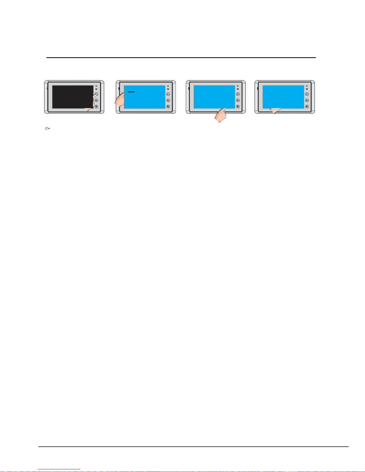
Shortcut for touch screen calibration of monitor
1 1 1
2 2 2
3 3 3
4 4 4
OK!
1
2
3
4
In standby mode,touch
the
unlock button and
hold
for
2s.
“+” icon will be shown
on
screen,then touch “+”
icon
until the icon move to
next
location.
The same as last operation. The same as last
operation.
When the screen display
“ok”,
that
means the screen
calibration
is
finished.
Page 23
PRO - System - Technical Guide
17
Bit state
Setting
Bit state
Setting
ON
1 2 3 4 5 6
The monitor is
not at the e nd of
the bus.
ON
1 2 3 4 5 6
The monitor is
at the end of
the bus.
ON
THIS IS ONLY REQUIRED FOR MULTI DOOR STATION SYSTEMS ONLY
User Code Setup – Room stations
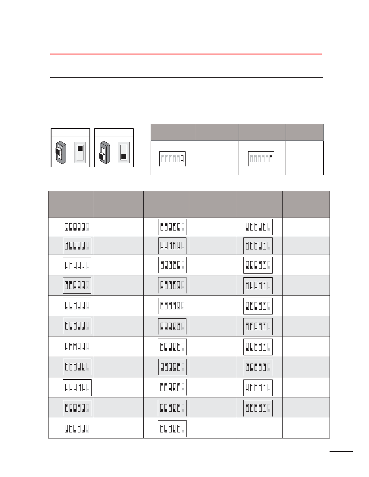
There are 6 bit switches in total. The DIP switches are used to configure the User Code for each Monitor.
Bit -6 is used to set video impedance, it should be set to ON if the Monitor is in the end of the line(bus), otherwise set
to OFF.
ON(1)
=
OFF(0)
=
-
1 to Bit -5 are used to User Code set ting. The value is from 0 to 31, which have 32 diff erent codes .
Bit state User Code Bit state User Code Bit state User Code
ON ON
ON
Code=0 Code=11
1 2 3 4 5 6
1 2 3 4 5 6
1 2 3 4 5 6
ON
1 2 3 4 5 6
Code=1 Code=12
1 2 3 4 5 6
ON
1 2 3 4 5 6
ON
Code=2
ON
Code=13
ON
1 2 3 4 5 6
ON
Code=3
1 2 3 4 5 6
ON
Code=14
1 2 3 4 5 6
ON
1 2 3 4 5 6
ON
Code=4
1 2 3 4 5 6
ON
Code=15
1 2 3 4 5 6
ON
1 2 3 4 5 6
ON
1 2 3 4 5 6
ON
Code=5
Code=6
1 2 3 4 5 6
ON
1 2 3 4 5 6
ON
Code=16
1 2 3 4 5 6
ON
1 2 3 4 5 6
ON
1 2 3 4 5 6
ON
Code=7
1 2 3 4 5 6
ON
1 2 3 4 5 6
ON
1 2 3 4 5 6
ON
1 2 3 4 5 6
ON
Code=8
Code=9
1 2 3 4 5 6
ON
1 2 3 4 5 6
ON
1 2 3 4 5 6
ON
1 2 3 4 5 6
ON
1 2 3 4 5 6
ON
Code=10
1 2 3 4 5 6
ON
1 2 3 4 5 6
1 2 3 4 5 6
1 2 3 4 5 6
Page 24
18
BT1
BT2 EH
GND
VD
BT1 BT2 EH
GND
VD
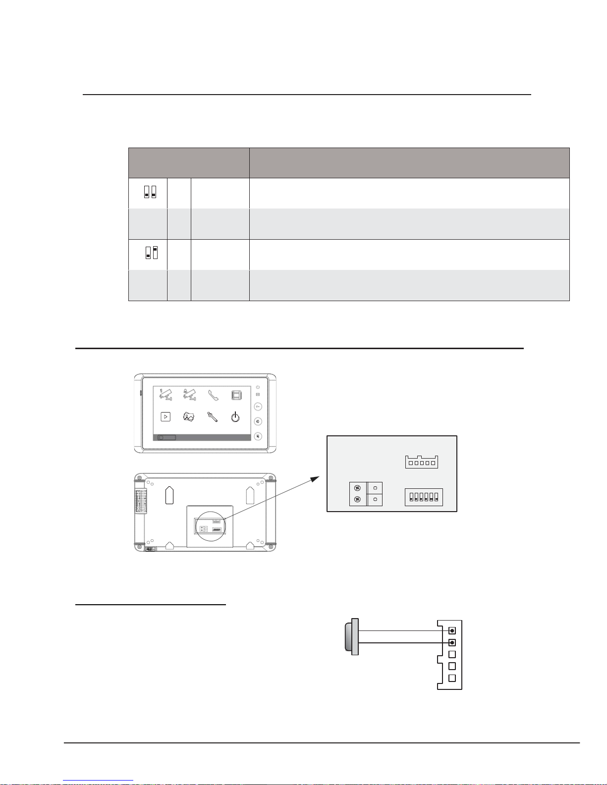
DIP user code settings for door station –
Total 2 bits on the DIP switches can be configured. The switches can be modified either before or after
installation.
Bit state
Descriptions
ON
1 2
Default setting, ID = 0(00), set to the first Door Station.
ON
1 2
ID = 1(10), set to the second Door S tation.
ON
1 2
ID = 2(01), set to the third Door S tation.
ON
1 2
ID = 3(11), set to the fourth Door Station.
Monitor Extending Connection
Manual
Monitor
Monitor
Intercom Multimedia
Memory
Playback
Album User Setup
Close
?
About
09/30/2010 Thu.16:41
L1
ON
DIPS
L2
1 2 3 4 5 6
L1 ON
DIPS
L2
1 2 3 4 5 6
1. Door Bell Call Button
Additional doorbell call button can be connected to the Mon
itor, so that the visitors can ring the doorbell again in front
of the user's apartment. When the call button is pressed, the
Monitor will output ring tones but the screen will keep off,
and the external ringer will ring at the same time (if a external
ringer is i nstalled) .
Door bell call button
SW+
SW-
EXT-RING
GND
VIDEO
Page 25
PRO - System - Technical Guide
19
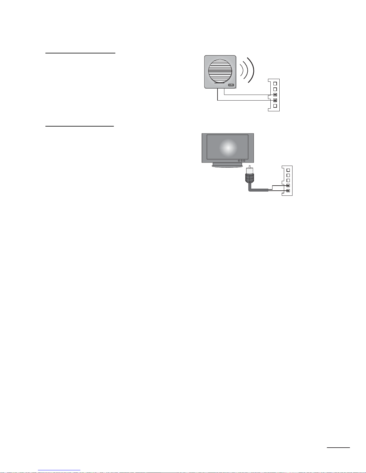
2. External Ringer
External ringer can be connected to the Monitor. The ringer
External Ringer
=
will ring whenever the Door Station call button or the door =
bell call button is pressed, and it will stop ringing when the
Monitor rejected or answered the call.
-
+
12Vdc 300mA
SW+
SW-
EXT-RING
GND
VIDEO
3. TV -out function
Connect television to the Monitor, when the Door Station
calls, the user switch the channel to the AV channel, and the
visitor's video will show up on the screen of the television.
The core of the video cable must connect to the VD terminal,
and the shi elded layer connect to the GND.
Television
video cable
SW+
SW-
EXT-RING
GND
VIDEO
Page 26
20
9
65
18 9
38
97
Accessories
352
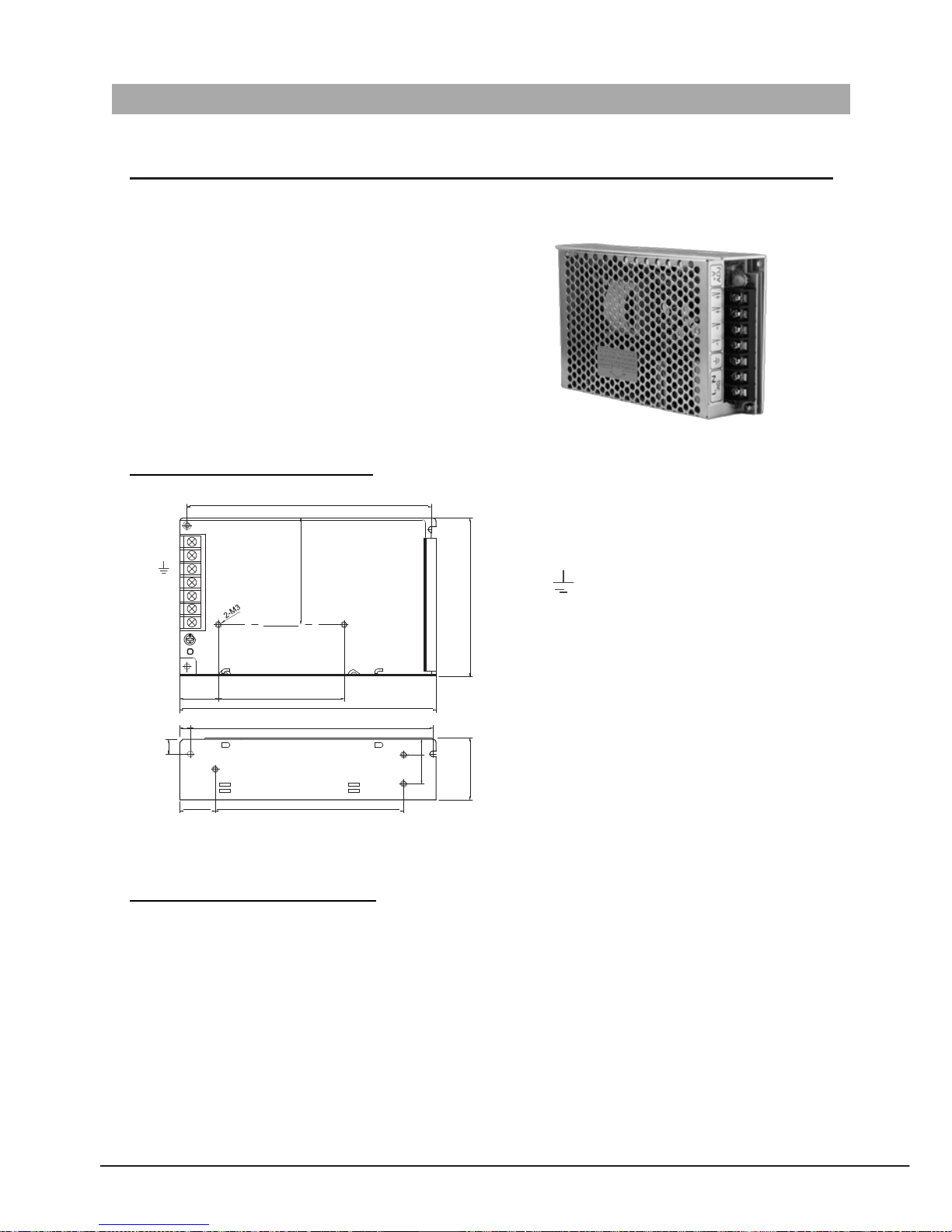
PS5 - Power Supply
The PRO-PS5 power supply unit is designed for PRO system to supply up to 32 Monitors and total 4 Door Stations at the
same time.
• Universal AC input/full range.
• Multi protection: short circuit, overload, over voltage
• Cooling by free air convecti on
• DIN rail mounting.
• Support up to 32 Monitors
• Support up to 4 Door Stations .
Dimension and Terminal
152.5
L (AC)
N (AC)
VV-
V+
V+
VADJ
LED
•
L(AC):
AC input.
•
N(AC):
AC input.
• : Earth Ground.
•
V-:
DC power output.(21.5~26.5 adjustable)
•
V+:
DC power output.(21.5~26.5 adj ustable)
24 78
159
6.5 150
•
VADJ:
Output vol tage adjust ment.
•
LED:
Working state indic ator.
22 117
Unit: mm
Electronic Specifications
Input Volta ge: 100~120VAC(2.5A), 200~ 240VAC(1.5A)
Input Fre quency: 50~60 Hz
Rated Output Voltage: 24Vdc
Rated Output Current : 4.5A
Working Temperature: -20
0
C~+600C
Dimension: 159(H)×97(W)×37(D)mm
Page 27
PRO - System - Technical Guide
21
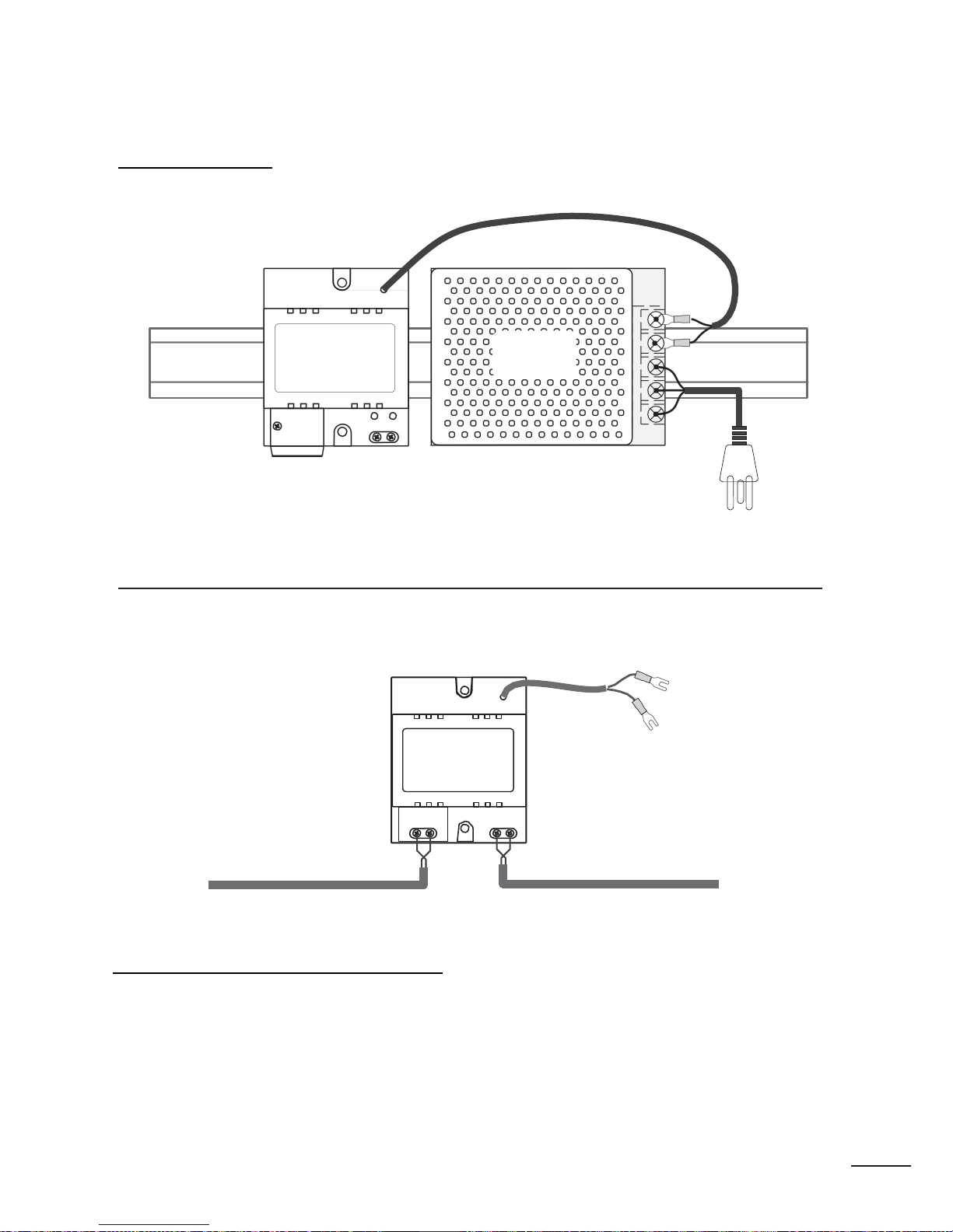
DIN Installatio n
352DPS
PROS5
DIN
nail
85~260AC
PRO
DPS
DPS:
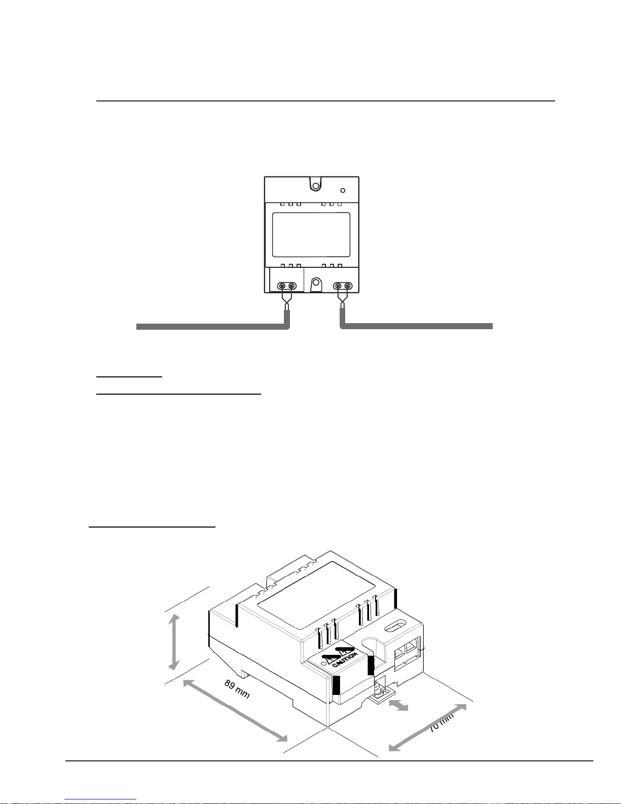
This unit is a power separator for the P ROS5 or PROS4 power supply, it transfers th e power from the power
supply to the suitable power for the non
-
polarity bus. Note that the PRODPS must work together with the
PROS5 or PROS4 power supply.
Connect to
PRODPS
Power
Supply(PROS5-24V)
Connect to Doo r
Station
Connect to
Monitor
Technical Specifications(PRODPS)
Power input: 24Vdc (supplied by PROS5)
Power output: 18Vdc
Power Consumption: 0.25W in standby, 0.5 W in workin g
Working temperature: -10ºC ~ +40ºC
Dimension: 89(H)×70(W)×45(D)mm
Page 28
22
45
mm
PRO
DBC
PRO
DBC:
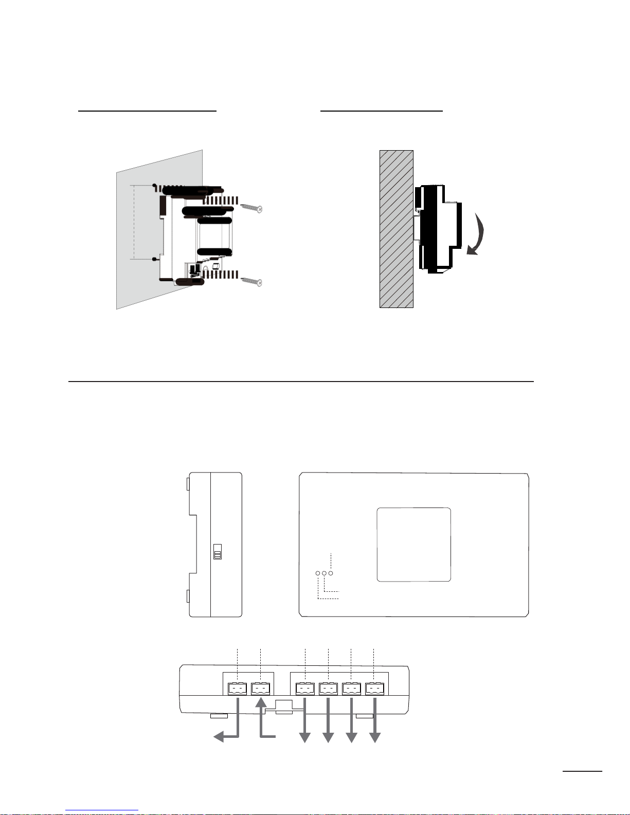
This unit is a 2 wire branc h controller unit used to transfer all data between the Monitor and the Bus Line. Every
Monitor(except the last one at the end of the line) needs one DBC to connect to the Non
-
polarity Bus Line. No extra
power supply needed, and one LED indicat or to show the working s tate.
PRODBC
Bus In/Out
Bus Out(to M onit o r)
Technical
Specifications(PRODBC)
Power Consumption: 0.25W in standby, 0.5 W in working
Working temperature: -10ºC +40ºC
Dimension: 89(H)×70(W)×45(D)mm
PRO
DBC Dimensions
Page 29
PRO - System - Technical Guide
23
Direct Wall Mounting DIN Rail Mounting
Use the screws to fas ten the unit on the wall directl y. Install on the DIN Rail.
85mm
PRODBC 4S Unit
PRODBC-4
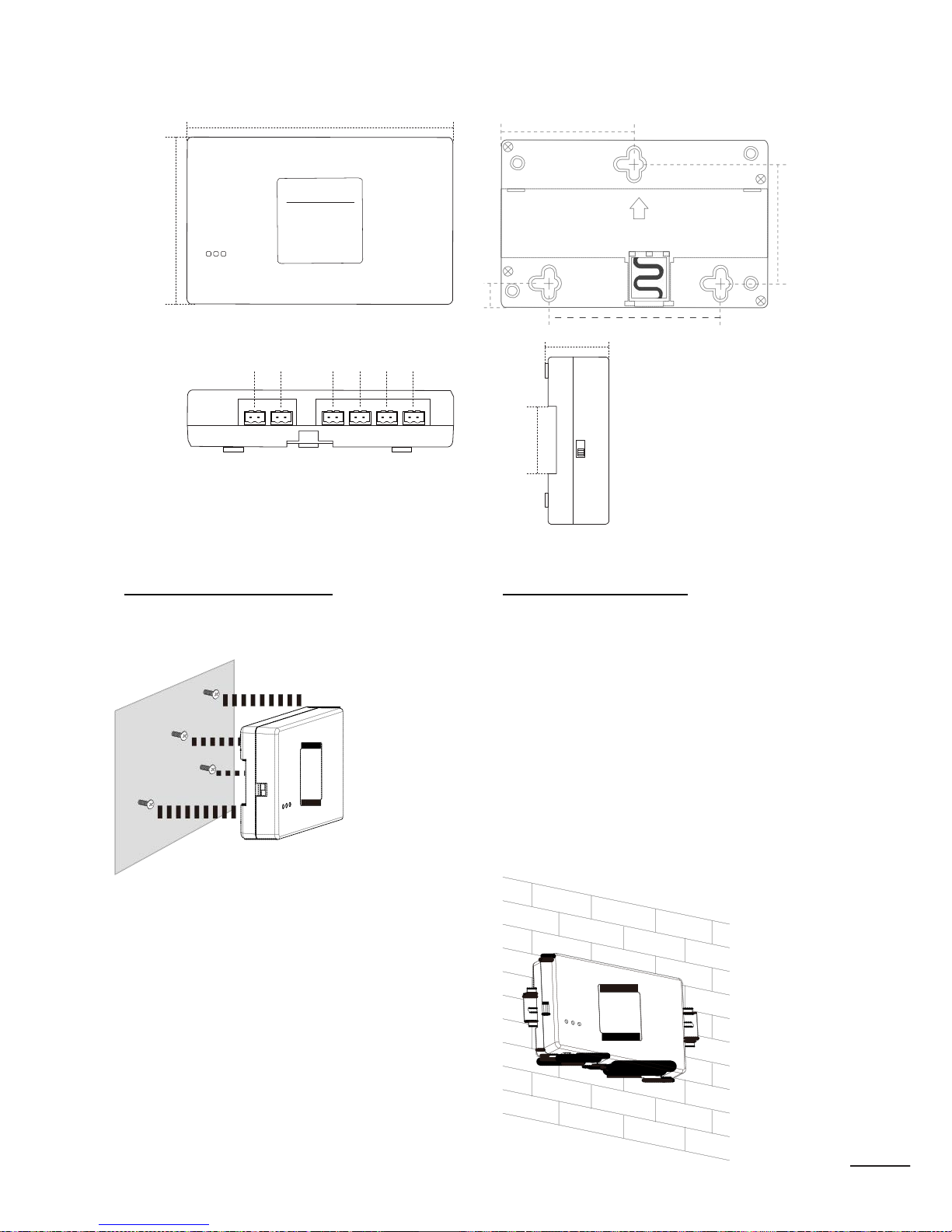
Distributor is a 2 wire branch controller with 4 outputs distributor for the Challenger Pro system, to approach
the star topology connection in the apartment system. See Section 3 Cables and Connection for detail con nection
information.
set to 120 for the last DBC-4
on the building, the others
must be set to HI.
HI
120
Video Match
PRODBC4S
In-use
Power
Trunk Bus
D C B A
Bus Out Bus In
Connect to Monitors
Page 30

24
Technical S
pecifications(PRO
DBC4S)
Power Supply : DC24V T
emperature:
-100C~+400C; Wiring: 2 wires (non -polarity); Dimension:
88(H)×140(W)×32(D)mm
PRO
DBC4S
Dimensions
Page 31
PRO - System - Technical Guide
25
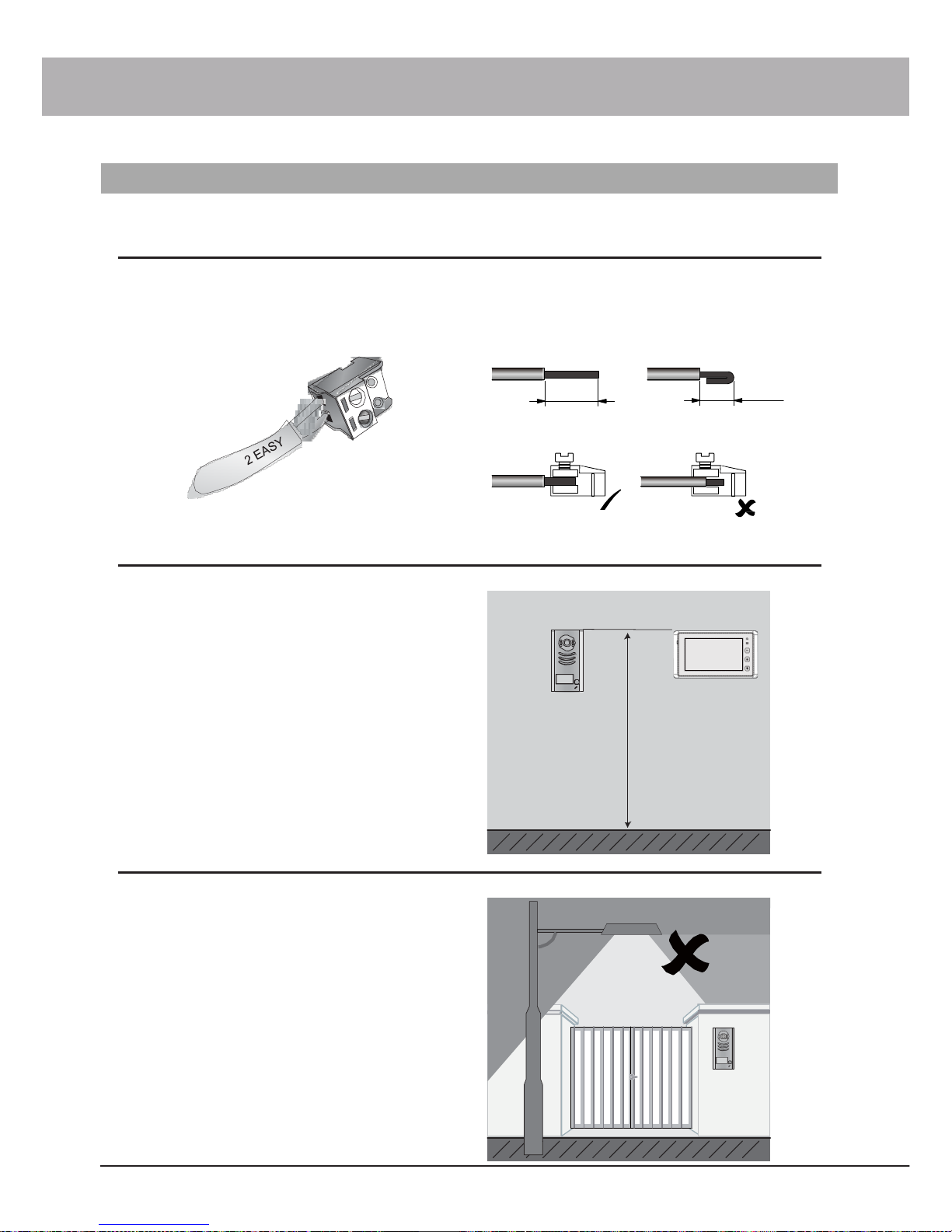
88mm
13mm
36mm
62mm
140mm
70mm
upward
32mm
84mm
Trunk Bus
D C B A
HI
A/B/C/D port: Connect to Monitors/Door Station
Trunk Bus: Bus input/output.
120
Direct Wall Mounting DIN Rail Mounting
Page 32
26
Section3 - Cables and Connections
General Rules for Installation
Connecting the Connectors
Before screw the wire to the plug -in connector, it's important to process the wire in the correct way. See the following
steps to c onnect the wire.
1. Strip the wire 2. Twist and bend it
~12mm 7~8mm
3. Put only the insulation-free part in the terminal
Installation Height
The recommended installation height of both Door Sta
-
tion and Monitor is f rom 160~165 cm.
1
2
3
4
160~165 cm
Door Station Install Condition
The Door Station cannot be installed in a place that
hard/large light sources can cover the lens of the
camera(for example, the street light or Sun light),
otherwise the video image will have lower contrast. If
there is no way to avoid this condition, the alternative is
to install the Door Station in a higher position and then
adjust the camera angle towards down to keep the lens
away from the light source.
Page 33
PRO - System - Technical Guide
27
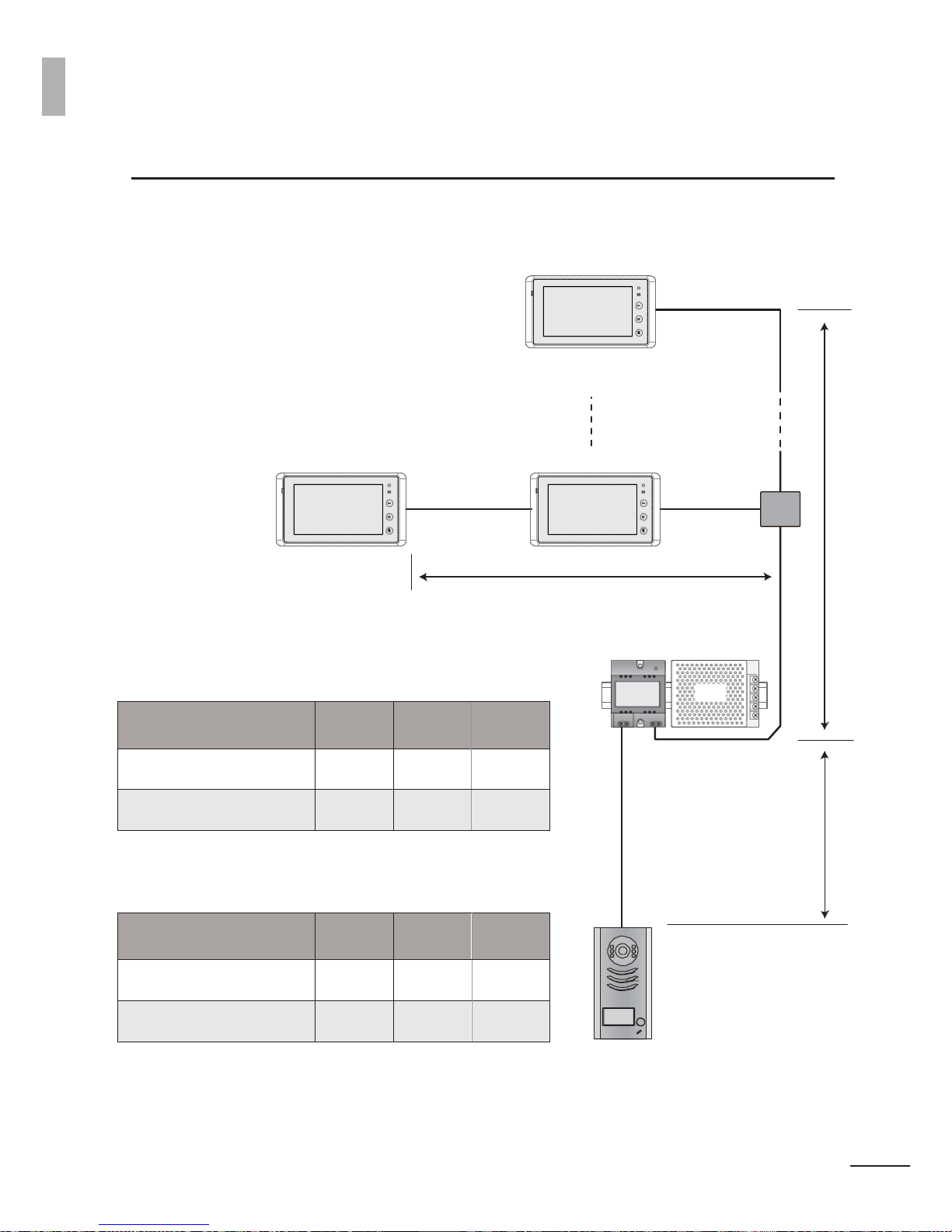
Cable Usage
A B
C
Twis ted cable 2x0.75 mm
2
60 60 30
Twis ted cable 2x1 mm
2
80 80 40
B
Table of Cables and Distance
The maximum distance of the wiring is limited in the Challenger Pro system. Using different cables may also
effect the maxi
-
mum distance the syst em can reach.
The farest
monitor
1
2
3
4
DBC
1
1
2
2
3
3
4
4
C
When Monitor quantity < 20
DPS PS5
A
When Monitor quantity > 20
Cable Usage
A B
C
Twis ted cable 2x1 mm
2
70 30 20
Twis ted cable 2x1.5 mm
2
70 50 30
The wire for the Non -polarity bus MUST non -shielded! And using the twisted wire is recommended,
if using the Non
-
twisted wire, the total distanc e will be half.
Page 34
28
ON
1
2
System Wirings and Connections
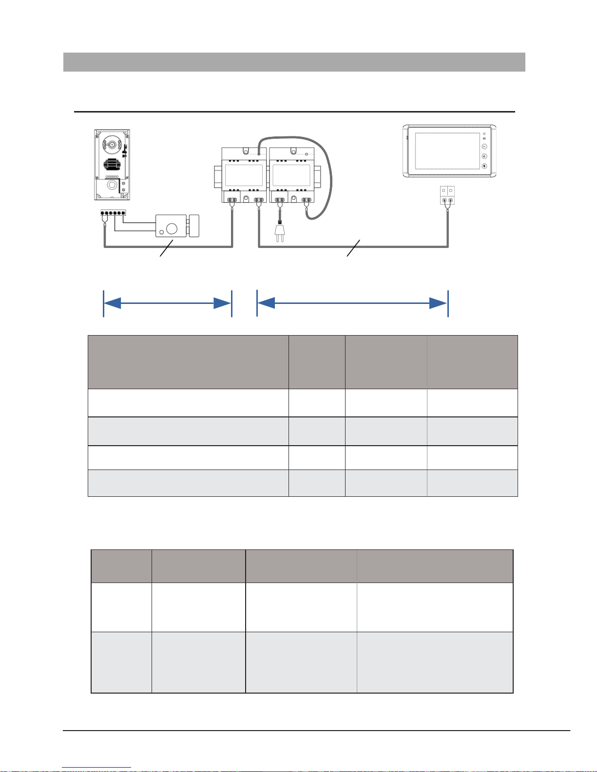
1. Basic one to one wiring and Cable Length
1
2
3
4
PRODPS
PROS4
L1 L2 PL S1+ S2+ S-
-
+
NP
AC~
NP
NP:Non-polarized
A B
Cable A(m) B(m)
≤2 PRO27
B(m)
≤16 PRO27
CAT5 Cable (Combined)
40 80
- - - -
Pair Cable (Parallel) 2X0.75 mm
2
30 50
- - - -
Twisted Cable 2X0.75 mm
2
60 100 40
Twisted Cable 2X1.0 mm
2
80 120 60
Here is a table for description of the two power supplies
Item Input Output Application
PROPS4-24V
AC 100 -240V DC 24V 1A
Just can power the sy stem with one
door station an d one mo ni tor (P RO 16
can be connected two).
PROS5-24V
AC 100 -120V 2.5A &
AC 200 -240V 1.5A
,AC
input voltage can be
selected by swit ch.
DC 24V 4.5A Volta ge ad
-
justable: 21 to 27V, default
is 24V
Can use it in all situation
Page 35
PRO - System - Technical Guide
29
2
2
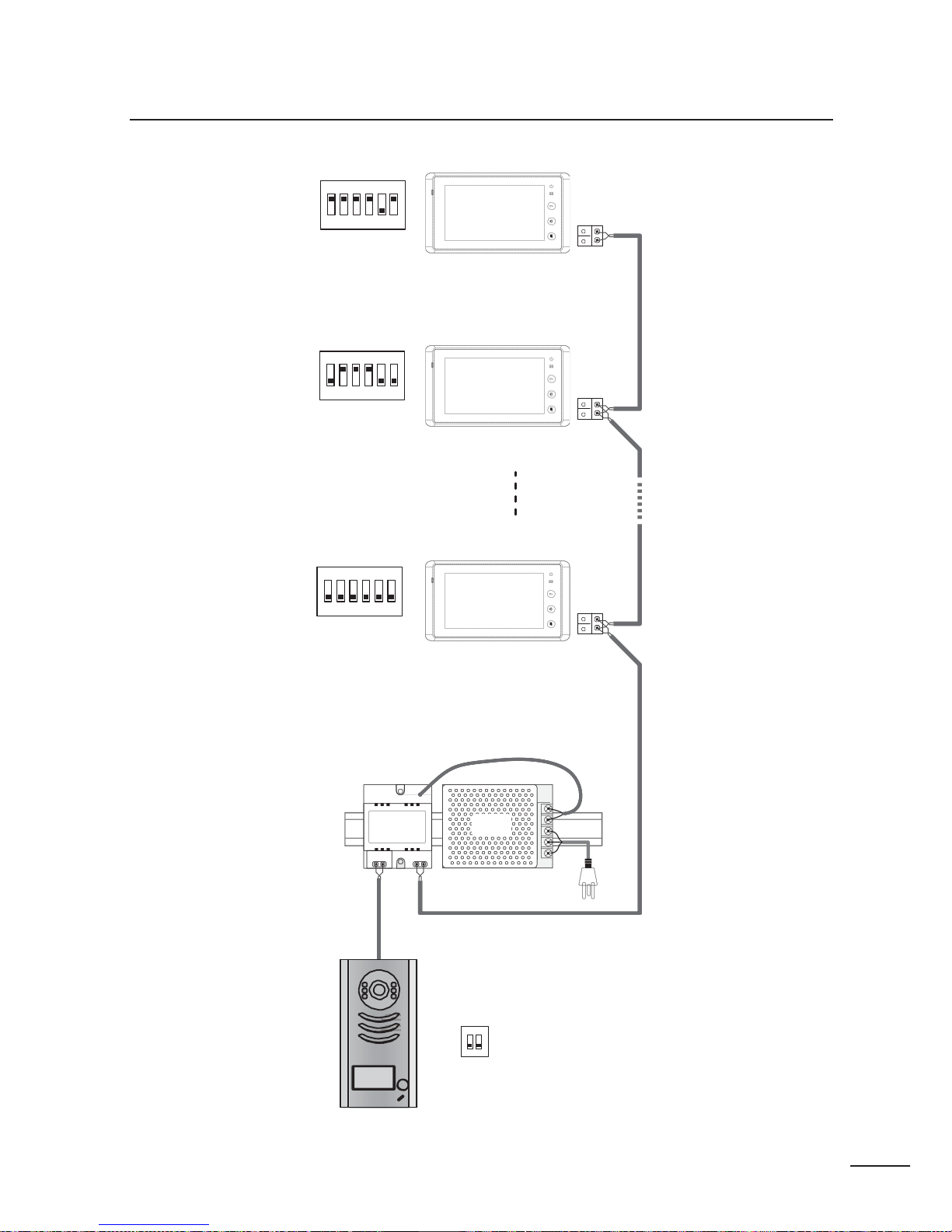
2. Multi monitors IN -OUT wiring mode
ON
1 2 3 4 5 6
1
3
4
Code=15, DIP-6=on
ON
1 2 3 4 5 6
1
2
3
Code=14, DIP-6=off
4
ON
1 2 3 4 5 6
1
3
4
Code=0, DIP-6=off
DPS
PS5
85~260AC
ID=00
ON
1 2
Page 36
30
DBC-4
DBC-4
OUT
IN A B C D
OUT
IN A B C D
1 2 1 2 1 2 2
4
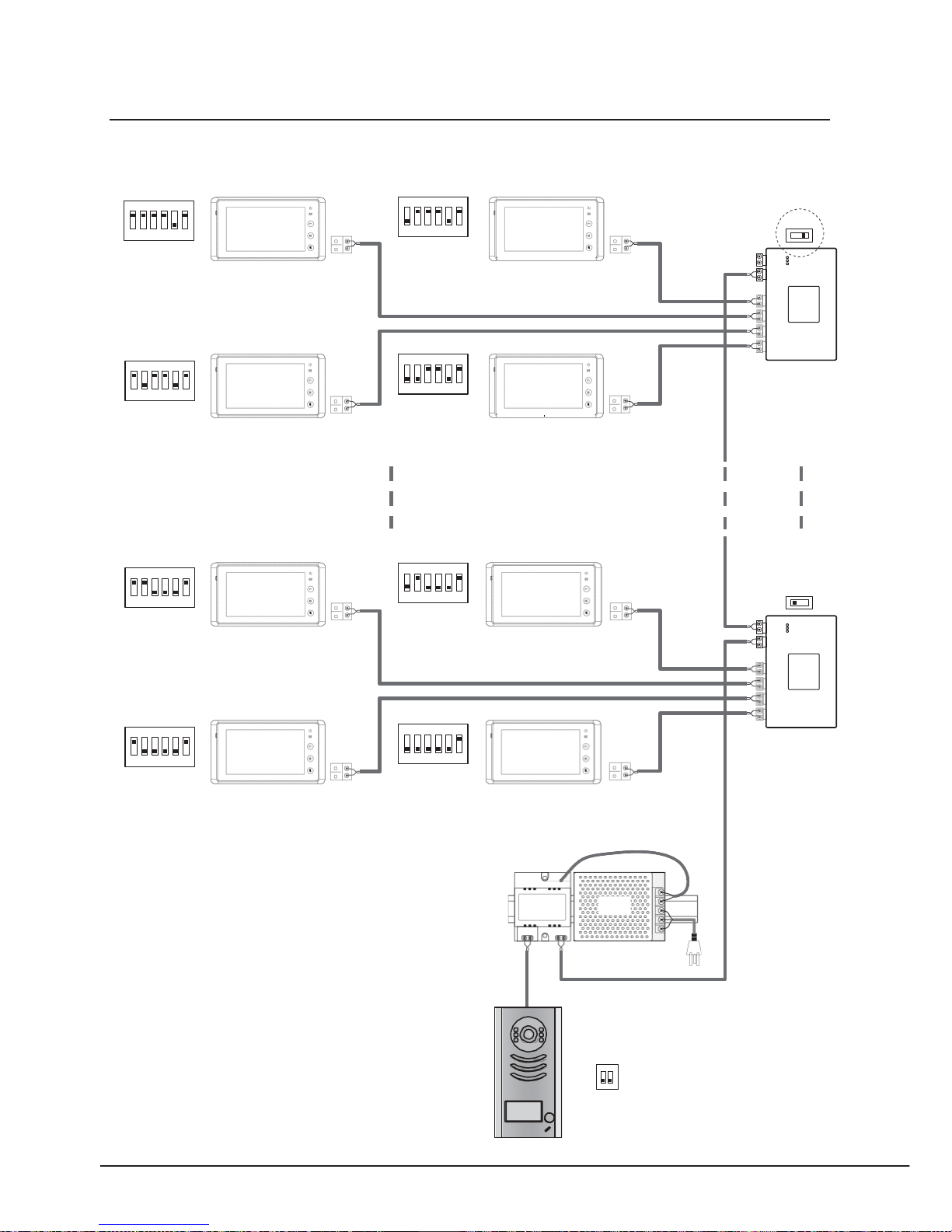
3. Multi monitors Star wiring mode
ON
ON
1 2 3 4 5 6
1
2
3
HI
1 2 3 4 5 6
2
3
4
Code=15, DIP-6=on
Code=14, DIP-6=on =
4
ON
ON
1 2 3 4 5 6
1
1 2 3 4 5 6
2
3
4
Code=13, DIP-6=on
3
Code=12, DIP-6=on =
4
ON
ON
1 2 3 4 5 6
1
3
4
Code=3, DIP-6=on
1 2 3 4 5 6
2
3
4
Code=2, DIP-6=on
ON
ON
1 2 3 4 5 6
1
3
4
Code=1, DIP-6=on
1 2 3 4 5 6
1
3
Code=0, DIP-6=on
DPS
PS5
85~260AC
ID=00
ON
1 2
Page 37

PRO - System - Technical Guide
31
Section4 -System Setup
• Pick -up waiting time: this is the duration from when a call is made from a Door Station to when the called
monitor i s picked up; the syst em will cut off the call after this period of time.(the default setting is 30 seconds)
• Maximum talking time: this is the duration time that the indoor user can talk to the out door visitor. After this
period the convers ation will be cut off automatically by the system to f ree the lin e.(the def ault setting is 90 seconds)
• Maximum intercom time: this is the duration time that the indoor user can talk to the other indoor user when
having an intercom conversation. After this period the conversation will be cut off automatically by the system to
free the line.(the d efault setting is 30 seconds)
• Maximum monitoring time: this is the duration time that the indoor user can monitor (surveillance) via the Door
Station, when press the Monitor button o n the Monitor.( the default setting i s 30 seco nds)
• Busy time: this indicates the period when a door unit can not place calls because a previous call or conversation
is in progress.(maximum busy time = pick
-
up waitin g time + maxi mum talking time)
What’s User Code
In 2 -wire CHALLENGER PRO system, each Monitor installed in system must be programmed with a calling address or
calling number, which is User Code.
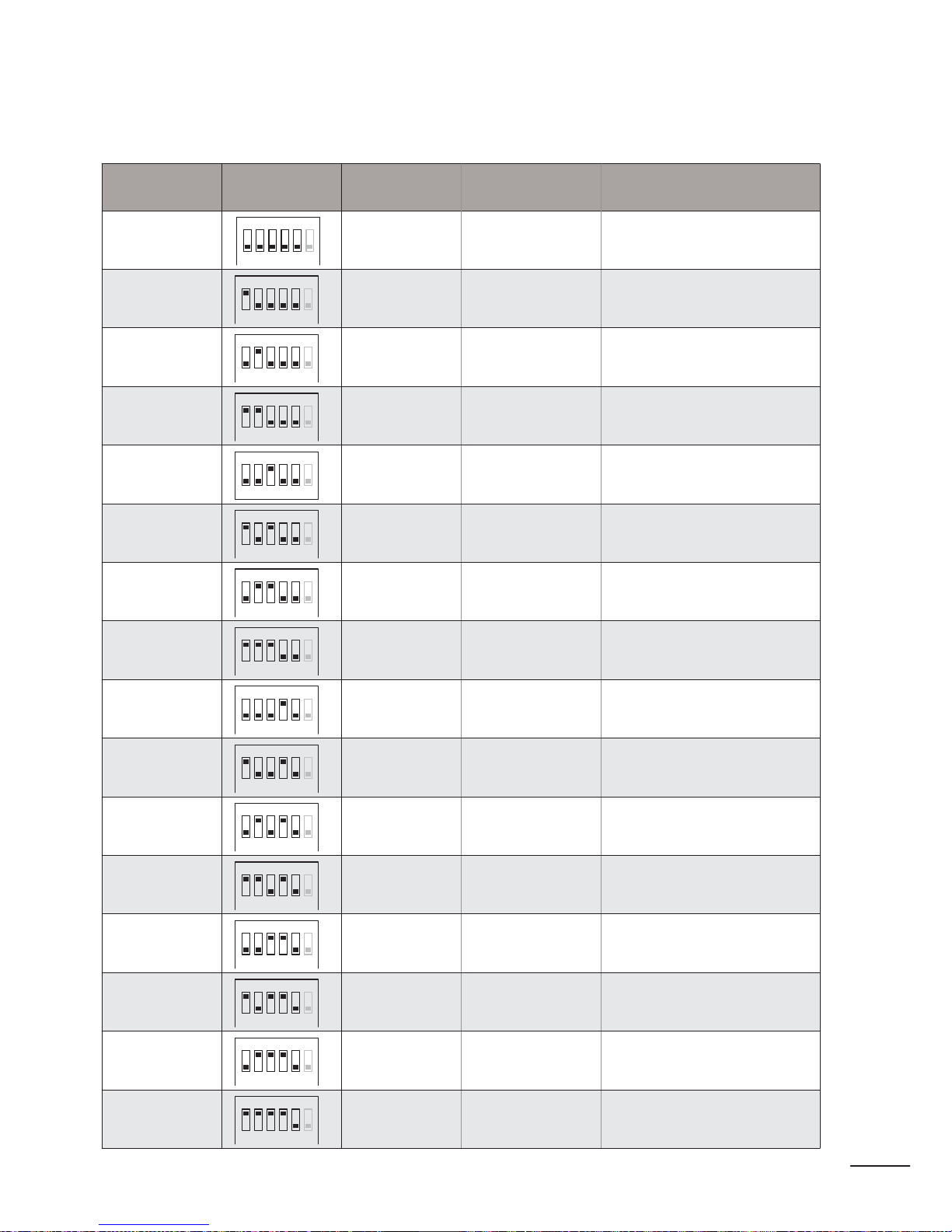
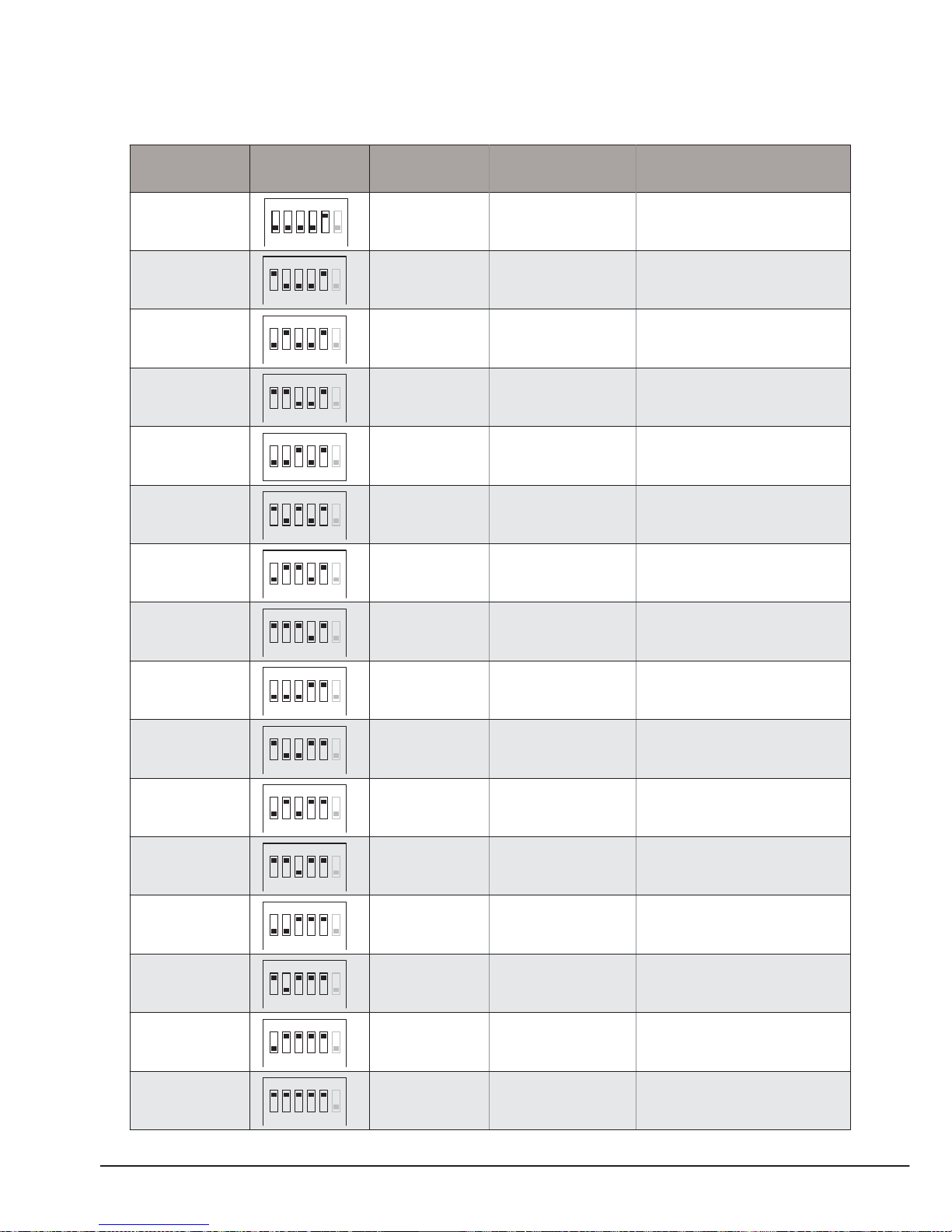
For Monitor, User Code is defined by 1~5 bits DIP switches on the connection board, according the User Code rules.
For example, if you want to program the Monitor’s User Code to be “03”, the Monitor’s 1~5 bit DIP switches should
be set as: ON, ON, OFF, OFF, OFF(please r efer to User C ode table at section2
-
Monitor).
For Door Station, the Call Button on panel is assigned to a specified User Code, and press this button will call re
lated Monitor. For example ,for PRO592, press the below call button , system will launch a call to the Monitor which
programmed with “00~15” User Code. Press the above call button system will launch a call to the monitor which
pro
grammed wi th "16~32" user code.
What's Slave Address
2 –wire CHALLENGER-PRO system is capable of connectin g up to 4 Monitors in on e apartment, which means they will have
the same
U•ser Code, and will be called si m ultaneously. In this condition, the Monitors shoul d be pr o gram m ed as below:
All the Monitors of same apartment must be programmed with the s ame User Code on the DI P switches.
• There is only one master Monitor in the one apartment, and the Slave Address of the master Monitor is set to 0.
Each Slave Monitor should be s et from 1~3.
• By default, Monitor’s Slave Address is preset to 0(master Monitor).
• By default ,when Door Station calls, only the master Monitor will turn on the screen, the slave Monitor will only
ring.
Page 38

32
Master Monitor Slave Monitor 1 Slave Monitor 2 Slave Monitor 3
Slave
Address
0
Slave
Address
1
Slave
Address
2
Slave
Address
3
Please note, when called by Door Station, all Monitors will ring, however, only the Monitor which Sub User Code was
programmed to 0 will turn on the screen by default.
Programming Slave User Code is by means of Monitor Menu, for more detailed operation, please refer to the
followings as below:
Installation setup on monitor
How to set the monitor as a Guard Monitor
A Monitor can be assigned as Guard Unit Monitor; when the Guard Unit Monitor answers the call,
conversation with the guard person is started..
The code number of 8004 is used to set the monitor as a guard unit monitor and 8005 is used to cancel
this function.
Page 39
PRO - System - Technical Guide
33
CHALLENGER PRO User Code Pr ogramming
Table page1/2
User code Bit state Room Name Label Remark
ON
00
1 2 3 4 5 6
ON
01
1 2 3 4 5 6
ON
02
1 2 3 4 5 6
ON
03
1 2 3 4 5 6
ON
04
1 2 3 4 5 6
ON
05
1 2 3 4 5 6
ON
06
1 2 3 4 5 6
ON
07
1 2 3 4 5 6
ON
08
1 2 3 4 5 6
ON
09
1 2 3 4 5 6
ON
10
1 2 3 4 5 6
ON
11
1 2 3 4 5 6
ON
12
1 2 3 4 5 6
ON
13
1 2 3 4 5 6
ON
14
1 2 3 4 5 6
ON
15
1 2 3 4 5 6
Page 40
34
CHALLENGER PRO User Code Pr ogramming
Table page1/2
User code Bit state Room Name Label Remark
ON
16
1 2 3 4 5 6
ON
17
1 2 3 4 5 6
ON
18
1 2 3 4 5 6
ON
19
1 2 3 4 5 6
ON
20
1 2 3 4 5 6
ON
21
1 2 3 4 5 6
ON
22
1 2 3 4 5 6
ON
23
1 2 3 4 5 6
ON
24
1 2 3 4 5 6
ON
25
1 2 3 4 5 6
ON
26
1 2 3 4 5 6
ON
27
1 2 3 4 5 6
ON
28
1 2 3 4 5 6
ON
29
1 2 3 4 5 6
ON
30
1 2 3 4 5 6
ON
31
1 2 3 4 5 6
Page 41
PRO - System - Technical Guide
35
Provision Security Prod u cts Pty Ltd
www.provisioncctv.com.au
PRO System Technical Guide_V1.0
Page 42
DS-1 00:23
3
Monitor Select
Exit Home
Camera 1 ...
Camera 2 ...
Camera 3 ...
Camera 4 ...
Monitor Time Set ...
5. Intercom Function
Touch Intercom item on main menu page,there are
three items:Intercom Call...,Inner Call ...,Direct Call
Guard Unit...
Exit Home
Intercom
Intercom Call ...
Inner Call ...
Direct Call Guard Unit ...
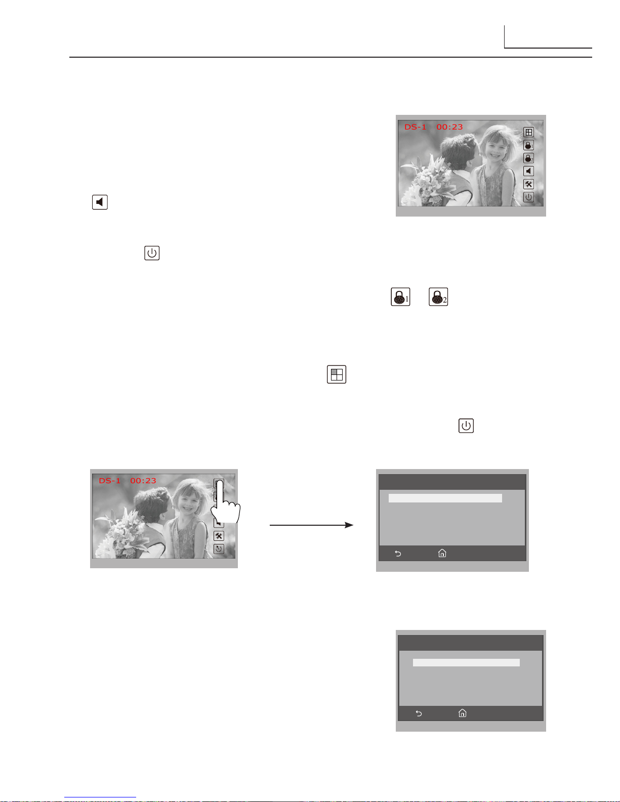
4. Basic Door Release Operation
1. Press CALL button on outdoor station, the
Monitor rings, at the same time, the screen
displays the visitors' image.
2. Press TALK/MON Button on monitor or touch
icon on screen, you can communicate hands
free with the visitor for 90 seconds.After nishing
communication,press TALK/MON button again
or touch icon to end the communication. If nobody answers the phone, the
screen will be turned off automatically after 30 seconds.
3. During talking state, Press UNLOCK Button or touch or icon to open the
corresponding door for the visitor.
4. When the monitor is in standby mode, press TALK/MON Button(or touch
Monitor ... item on main menu page), The screen can display the view of outside.
If multi door stations are installed, touch icon to get into the camera switch
mode(or direct touch Manual Monitor item on main menu page). You can
touch camera 1/2/3/4 to monitor the door station or CCTV camera you want.See
the following diagrams.(Press TALK/MON button again touch icon to end
monitoring.)
DS-1 00:23
Page 43
4
1.
Intercom Call
: User in one apartment can call
other apartments in the system. the namelist will
be created automatically by the system. Touch a
name you want on the screen, then touch icon
to dial.(Note:1. touch icon again to redial.
2.The DIP switches code of each monitor must set
different.)
2.
Inner Call
: If multi slave monitors are installed in the same apartment, select Inner
Call, all the other Monitors will ring at the same time, whichever Monitor answers
the call, conversation is started.and the other monitors will stop ringing at the same
time.(note:the DIP switches setting of all monitors must be same. )
3.
Direct Dial Guard unit
: A Monitor can be assigned as Guard Unit Monitor; when
the Guard Unit Monitor answers the call, conversation with the guard person is
started..
Exit Calling
Next Page
Intercom Call
[ 00 ] Jim. Zhang
[ 01 ] Calo. Liu
[ 02 ] Jacko. Zhang
[ 03 ] Philips. Chen
[ 04 ] Hebe. Zhang
[ 05 ] Tony. Li
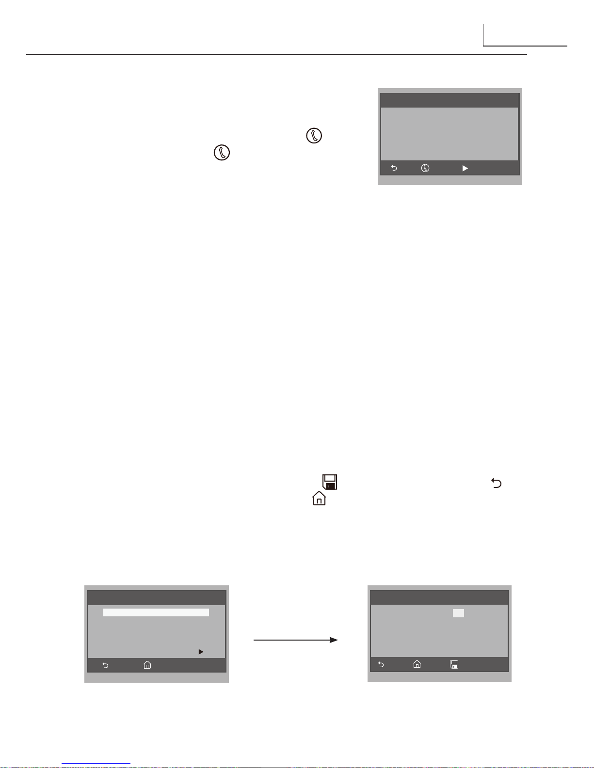
6. Basic Setup Instructions
Ring Tone Settings
Touch User Setup item on main menu page to enter setup page.Touch Door Station Call
Tone, Inercom Call Tone or DoorBell Tone item, There are 12 pieces ring tones can be
selected.touch a ring tone you want, then touch icon to save and exit.(touch icon
to cancel the setting and return last page, touch icon to get into main menu page)
Door Station Call Tone
:set the ring tone calling from outdoor station.
Intercom Tone
:set the ring tone calling from other apartments.
DoorBell tone
:set the ring tone calling from door bell.
Exit Home
User Setup (1)
Door Station Call Tone ...
Intercom Call Tone ...
DoorBell Tone ...
Clock ...
Next Page
Cancel Home Save&Exit
Door Station Call Tone
1 Carmen 5 Sonatine 9 Do Re Me
2 Ding Dong 6 Edelweiss 10 Happy Birthday
3 Rain 7 Going Home 11 Jingle Bells
4 For Alice 8 Congratulation 12 Telephone Ring
Selected: 06
Page 44
5
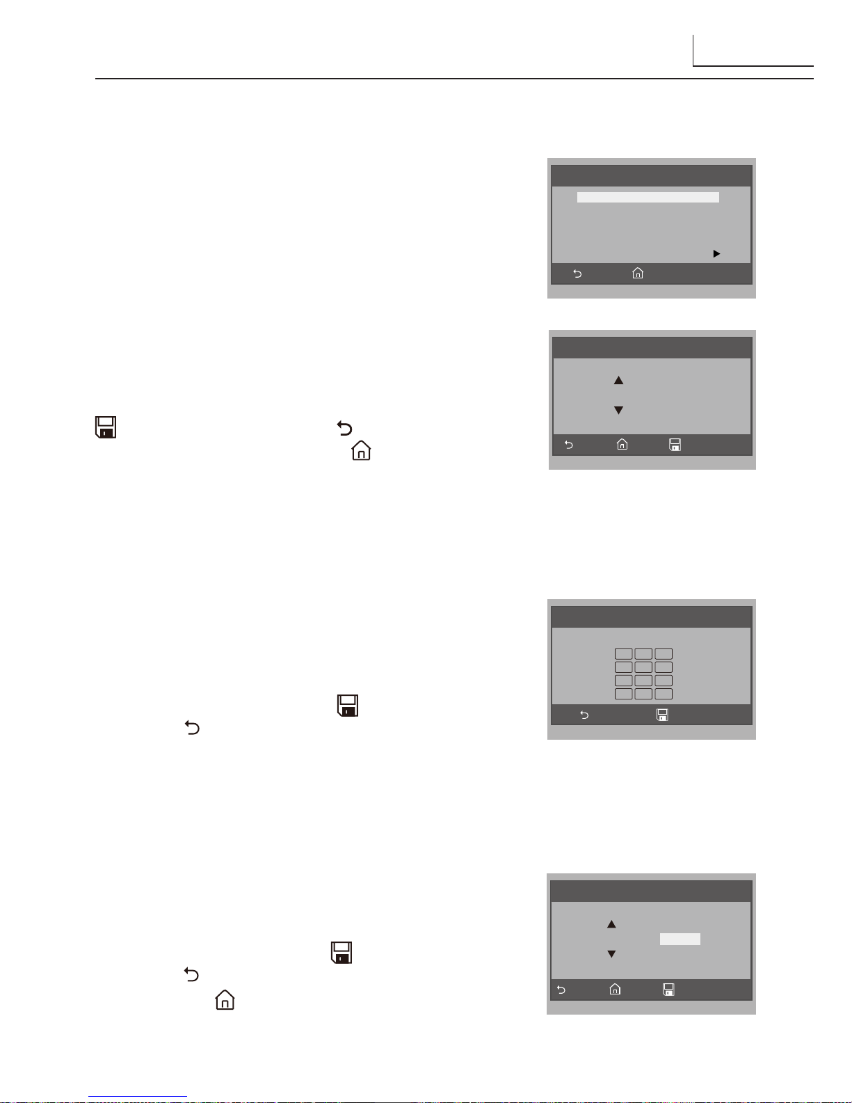
7. Date and Time Setting
Touch User Setup item on main menu page to enter
setup page, touch
Clock...
item. a digital keypad
will be showed on screen, input date and time by
touching the digital keypad,use * key to select the
setting item. After nish, touch icon to save and
exit.(touch icon to cancel the setting and return
last page.)
Cancel Save&Exit
Clock
2010 - 12 - 28 15 : 00
1 2 3
4 5 6
7 8 9
*
0 #
8. Monitor Time settig
Touch Manual Monitor item on main menu page
to get into camera switch mode, select
Monitor Time
Set...
item. touch ▲ / ▼ icon to increase / decrease
the value; After nish, touch icon to save and
exit.(touch icon to cancel the setting and return
last page, touch icon to get into main menu page)
Cancel Home Save&Exit
Monitor Time Select
Current : 01min
Ring Volume and Night Ring Volume Setting
You can set a ring volume for day time and night
time individually, 6:00 AM~18:00 PM is the day
time and 18:00 PM~6:00 AM is the night time by
default,if you don't want to be disturbed at night,you
can set the night ring volume to 0.
Touch User Setup item on main menu page to
enter setup page,then touch
Next Page
item to enter
User Setup 2 page, select
Ring Volume Setting or
Night Ring Volume
item. then touch ▲ / ▼ icon to
increase / decrease the value; After finish, touch
icon to save and exit.(touch icon to cancel the
setting and return last page, touch icon to get into
main menu page)
Cancel Home Save&Exit
Ring Volume
Current : 05
Exit Home
User Setup (2)
Ring Volume ...
Night Ring Volume ...
TPC Congure ...
Restore to default ...
Last Page
Page 45
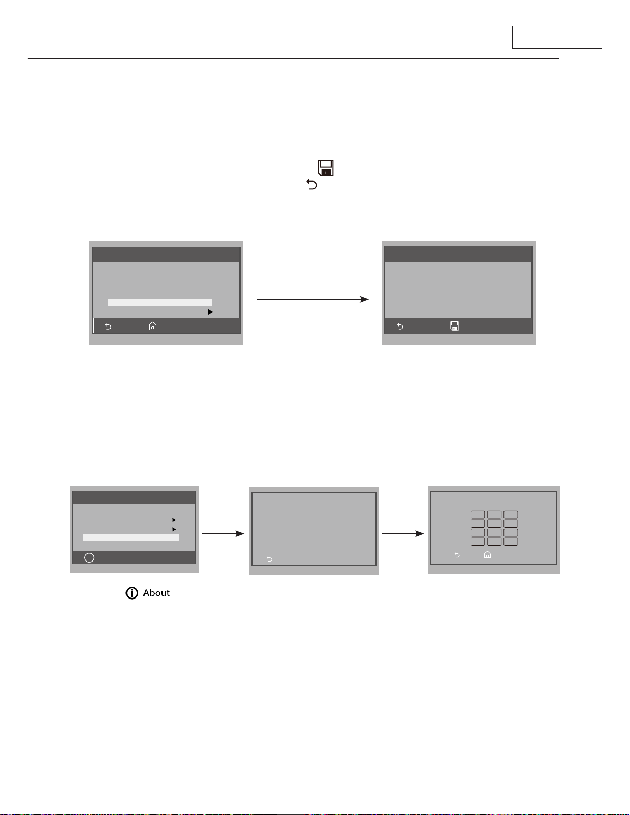
9. Restore to Default
Touch User Setup item on main menu page to enter setup page,then touch Next Page
item to enter User Setup 2 page, touch
Restore to default
item ,a message will be asked
to confirm the restore operation. If touch icon ,All settings will be restored to
default, if you don't want to restore, touch icon to cancel the operation.(Note that the
restore to default operation will not change the time setting and the datas.)
A Monitor can be assigned as Guard Unit Monitor; when the Guard Unit Monitor
answers the call, conversation with the guard person is started..
The code number of 8004 is used to set the monitor as a guard unit monitor and 8005 is
used to cancel this function.
Exit Home
User Setup (2)
Ring Volume ...
Night Ring Volume ...
TPC Congure ...
Restore to default ...
Last Page
Cancel OK
Restore to Default
Are you sure to
Restore all to default?
6
10. Monitor Parameter Setting
Main Menu
About
i
Monitor ...
Manual Monitor
Intercom
User Setup
Close
Exit
H/W : DT14-CT a1.3
S/W: V17.11.418.00
Local addr: --Unlock timing: --Unlock2 select: Video standard: Language: ---
Exit Home
Input Code Number:[- - - -]
1 2 3
4 5 6
7 8 9
*
0 #
1.Touch item
on main menu page.
2.Touc h the sc ree n
anywhere and hold for
2s.
3. A dig it al key pa d
will be showed.
How to enter the installation setting page
How to set the monitor as a Guard Monitor
Page 46
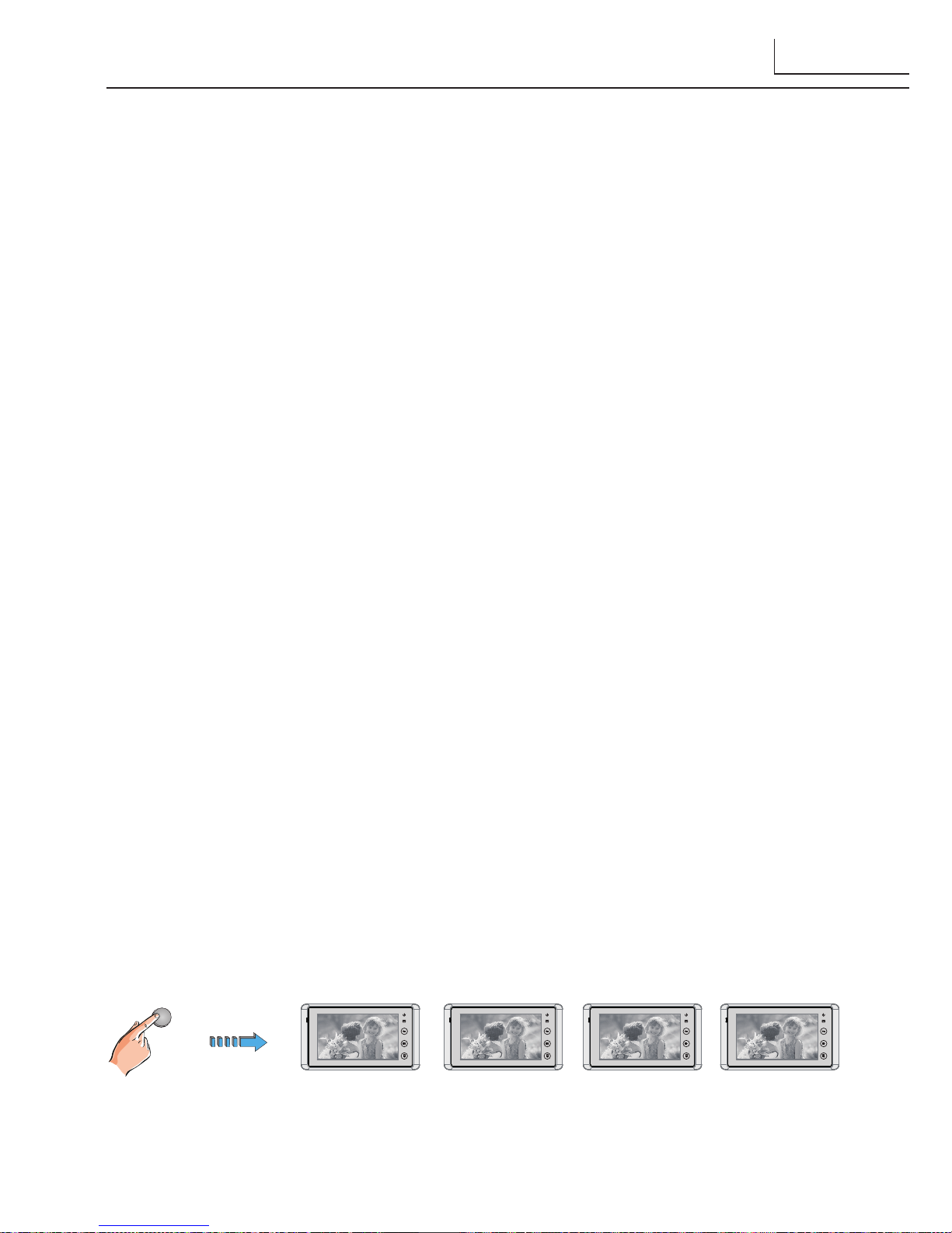
How to set the monitor panel on
In default mode,when receive a calling,the master and slave monitors will ring at the
same time,and just the master monitor can display the image while the slave monitors
can not.But the settings can be changed,you can set the master monitor and all the slave
monitors to panel on at the same time when receiving a call, just input the code number
of 8006 on each slave monitor.
1
2
3
4
1
2
3
4
1
2
3
4
1
2
3
4
How to set the slave monitor address
Maximum 4 monitors can be connected in one apartment,one master monitor together
with 3 slave monitors, so you should set the address correctly.(note:must have one
monitor to be set as master monitor)
The code of 8000 is used to set the master monitor.
The code of 8001 is used to set the rst slave monitor .
The code of 8002 is used to set the second slave monitor .
The code of 8003 is used to set the third slave monitor .
Note:touch * button to cancel the input,touch # to save the settings.
The system offers two methods of date and time.
The code number of 8008 is used to set the date format as month/date/year
The code number of 8009 is used to set the date format as date/month/year
The code number of 8012 is used to set the time format as 12 hour system
The code number of 8013 is used to set the time format as 24 hour system
.How to set date and time format
7
Page 47
The unlock time can be changed by yourself at any time.it can be set from 1 to 9 seconds.
The code number from 8021 to 8029 are used to set the unlock time to 1~ 9 seconds.
Unlock time:
How to set the menu language
The monitor can support multi languages and it is so simple and fast, just input the
corresponding language code on monitor.The language code number are as follows:
8101: English
8102: French
8103: Spanish
8104: Italian
8105: German
8106: Dutch
8107: Portuguese
8108: S-Chinese
8109: T-Chinese
8110: Greek
8111: Turkish
8112: Polish
8113: Russian
8114: Slovakia
8115: Hungray
8116: Czech
Note:the monitor can only support 4 types of languages.English,French,Spanish and
German are default.But you can customize any 4 languages by yourself.The language
which is unavailable will be set to English in default.
How to set the unlock parameter
There are two unlock modes: 1.power-on- to-unlock type:unlock mode=0(by default)
2.power-off-to-unlock:unlock mode=1.
The code number of 8010 is used to set the unlock mode to 0
The code number of 8011 is used to set the unlock mode to 1
Unlock mode:
8
Page 48
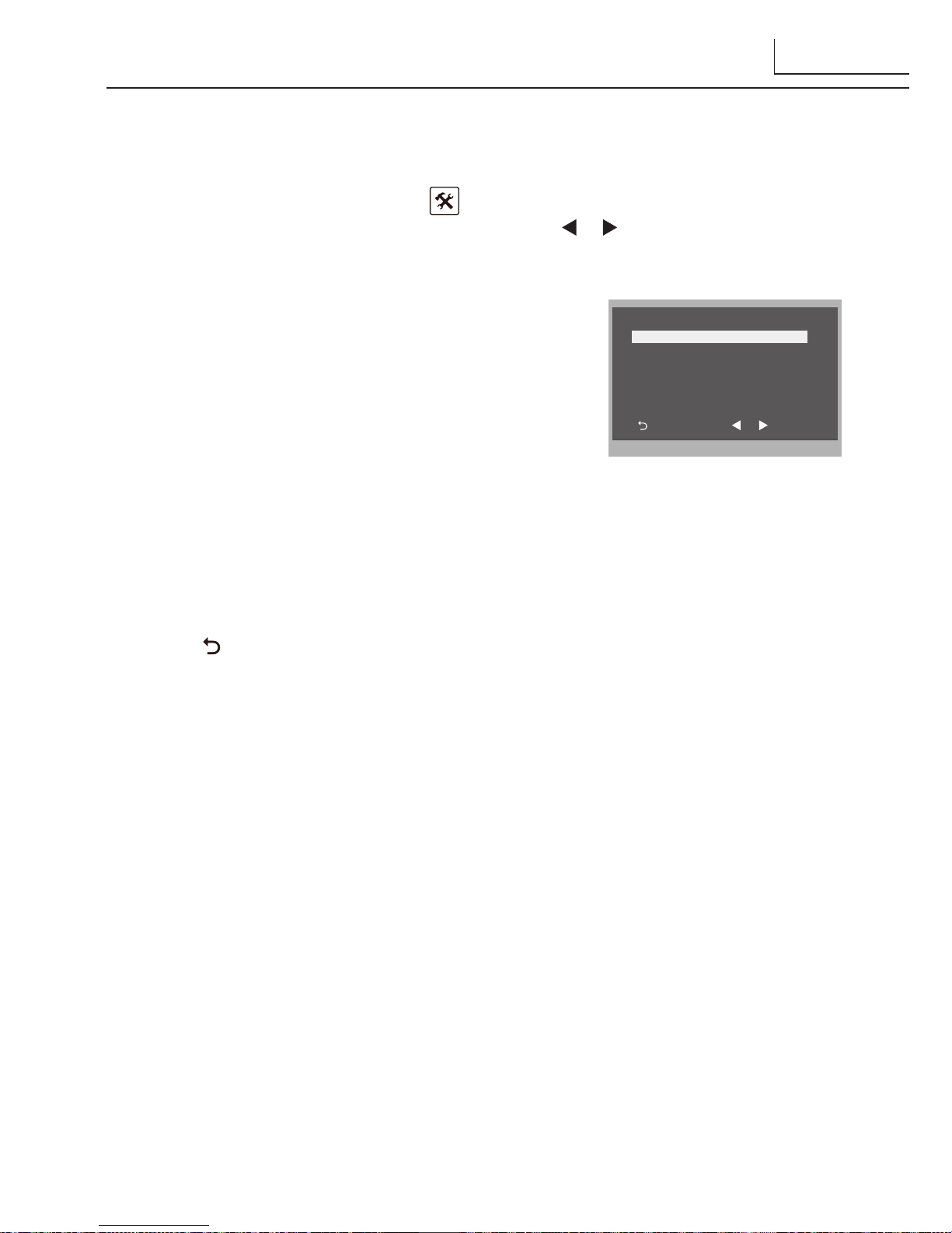
11. Screen and Volume Adjustment
During monitoring or talking, touch icon,the
ADJUST MENU
will be displayed.
Touch and select the adjustment item you want; touch / icon to decrease / increase
the value.
1. The first item is Scene mode selection: Total 4
screen modes can be selected in sequence:
Normal,
User, Soft
and
Bright.
Whenever you modify
Brightness
or
colour, Scene
item will be set to
User
mode automatically.
2. The
Brightness
and
Colour
item is for the image
quality setting, adjust the value to get the best
image you like.
3. The
Ratio
item is for screen display adjustment,you can set to 16:9 or 4:3.
4. The
Talk Volume
item is for talking volume adjustment.
5. Note that all the modications will be performed immediately after the operation.
Touch icon to exit the adjust page.
Exit
IncDec
Scene Normal
Bright 6
Color 6
Ratio 16:9
Talk Volume 2
12. Specication
●●Power●supply●for●indoor●monitor:●● ● DC●24V●
●●Power●consumption:● ●● Standby15mA;●Working●400mA
●●Monitor●screen:● ● 7●Inch●digital●color●LCD
●●Display●Resolutions:● ● 800*3(R,●G,●B)●x●480●pixels
●●Video●signal:● ● 1Vp-p,●75Ω,●CCIR●standard
●●Wiring:● ● 2●wires,●non-polarity
●●Dimension:● ● 125(H)×225(W)×23(D)mm
9
 Loading...