

Page 1

IC Radio Standards Specification: RSS-210
Manufacturer: Proventix Systems, Inc.
Certification Exhibit
FCC ID: ZNR-CU3000
IC: 9675A-CU3000
FCC Rule Part: 15.247, 15.249
ACS Project Number: 10-0364
Model: CU3000
Manual
5015 B.U. Bowman Drive Buford, GA 30518 USA Voice: 770-831-8048 Fax: 770-831-8598
Page 2

Eliminate the spread of infectious disease in healthcare and hospitals.
Implementation Guide
Page 3

4518 Valleydale Rd. Suite 201 • Birmingham Alabama • 35242
(205) 383 -1156
www.proventix.com
© 2010-2011 Proventix Systems, Inc. 2
Page 4

Table of Contents
About nGage............................................................................................................................. 5
About Proventix Systems, Inc.................................................................................................. 5
Purpose ..................................................................................................................................... 6
Implementation ........................................................................................................................ 6
Outline of Implementation ........................................................................................................... 7
Technical Specifications ............................................................................................................... 7
Site Planning................................................................................................................................ 7
Infrastructure .............................................................................................................................. 7
Coding and Validation ................................................................................................................. 7
Client Data Extraction ................................................................................................................. 7
Standard Operating Procedures................................................................................................... 7
Support Procedures ..................................................................................................................... 7
Terminology................................................................................................................................. 8
Implementation Plan.................................................................................................................... 9
Technical Specifications ............................................................................................................... 9
Hardware.............................................................................................................................................11
nGage Client Server............................................................................................................................11
SNAP® network ..................................................................................................................................11
Control Units (CU) .............................................................................................................................11
Bridge Unit..........................................................................................................................................11
System Architecture....................................................................................................................11
nGage Client Server Application ........................................................................................................12
Technology .........................................................................................................................................12
Network...............................................................................................................................................12
nGage Web Server .............................................................................................................................12
Infrastructure .............................................................................................................................13
Procure & Prepare...............................................................................................................................13
nGage Client Server............................................................................................................................14
Connect to Internet..............................................................................................................................14
Install Components .............................................................................................................................14
Client Data Extraction for Tracking and Reporting............................................................................14
Site Planning...............................................................................................................................16
Floor Plan............................................................................................................................................17
Assign Locations.................................................................................................................................17
Approvals............................................................................................................................................18
Coding and Validation ................................................................................................................18
© 2010-2011 Proventix Systems, Inc. 3
Page 5

Code Configuration.............................................................................................................................18
Validate Configuration........................................................................................................................18
Perform Proventix Test Run ...............................................................................................................18
Perform Client Data Extraction Test Run...........................................................................................18
Standard Operating Procedures (SOPs)......................................................................................19
Changing Tags ....................................................................................................................................19
Moving CUs........................................................................................................................................19
Monitoring Operation .........................................................................................................................19
Support Procedures ....................................................................................................................19
Time of Operations .............................................................................................................................19
Contact Numbers ................................................................................................................................19
nGage Client Server................................................................................................................20
Requisite Functions.....................................................................................................................20
Server Hardware ........................................................................................................................20
Server Software ..........................................................................................................................21
Network Diagram .......................................................................................................................21
Network Elements.......................................................................................................................22
Appendix .................................................................................................................................23
Frequently Asked Questions ...................................................................................................25
© 2010-2011 Proventix Systems, Inc. 4
Page 6
About nGage
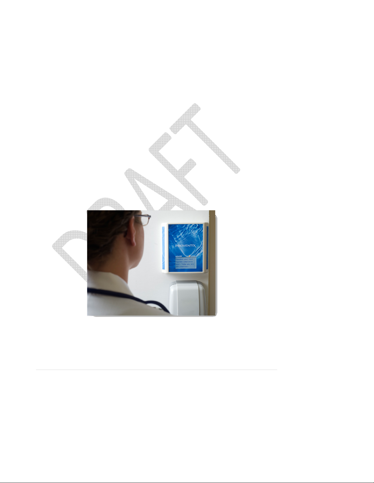
Our lead healthcare product, nGage™, is a point of care system that motivates workers to seek out hand
hygiene opportunities. The person, while engaged in washing their hands, is rewarded with important
professional, performance and user-defined content through an active communication display unit. RFID
tags are used to monitor compliance and create data for hospital executives and managers. nGage is an
expandable communications and device infrastructure that will improve compliance and create
opportunities for efficiencies.
About Proventix Systems, Inc.
Proventix™ is a technology company whose mission is to eliminate the unnecessary human and economic
costs of infectious diseases in the healthcare and hospitality industries. We provide tools and services for
quality compliance monitoring, active point of care communication, and successful behavior
modification.
© 2010-2011 Proventix Systems, Inc. 5
Page 7
Purpose
This document describes implementation of the nGage system. The document focuses on approach,
scope, and explanation of concepts pertaining to the system. Each installation is defined by a specific,
individualized plan of action and such plan of action may refer to the items described in this guide.
The document includes:
• Technical Specifications
• Outline of Implementation
• Implementation Plan
• Infrastructure
• Site Planning
• Coding and Validation
• Standard Operating Procedures
• Support Procedures
© 2010-2011 Proventix Systems, Inc. 6
Page 8

Implementation
The goal of the implementation process is to build a network of the individual sensors and tags and to
connect it to the server software. The major phases outlined below are discussed in further detail later in
the document.
Outline of Implementation
Technical Specifications
This outlines devices and hardware.
Site Planning
This creates a depiction of the physical environment (floor plan) with the positions of the individual units
depicted and named.
Infrastructure
This is the outline of what is needed to support the installation of the nGage system.
Coding and Validation
This describes the process of coding the positions, tags, staff, and other configurations of the nGage
system. The validation of the system implementation is outlined.
Client Data Extraction
HL7 – ADT and HIS Census data feeds to Proventix server.
Standard Operating Procedures
This describes the standard operating procedures for operating the nGage system. It only includes
activities that may be done by the key operator at the client site. All other activities will be performed
under the support category.
Support Procedures
This describes the support procedures.
© 2010-2011 Proventix Systems, Inc. 7
Page 9
BR
CU
CU
The implementation of the nGage system will determine the utility of the product within the hospital
environment. The system gathers information from multiple Radio Frequency (RF) devices and stores data
in a useful form inside the server database. The reporting database is accessible to authorized users via
SSL-encrypted Internet connection. The validity of the installation depends on establishing and keeping all
referential information correct.
Terminology
In order to understand the implementation, one must have a good understanding of the individual
elements of the nGage network.
CU
CU
TAG
BR
CU
Server
TAG
CU
BR
TAG
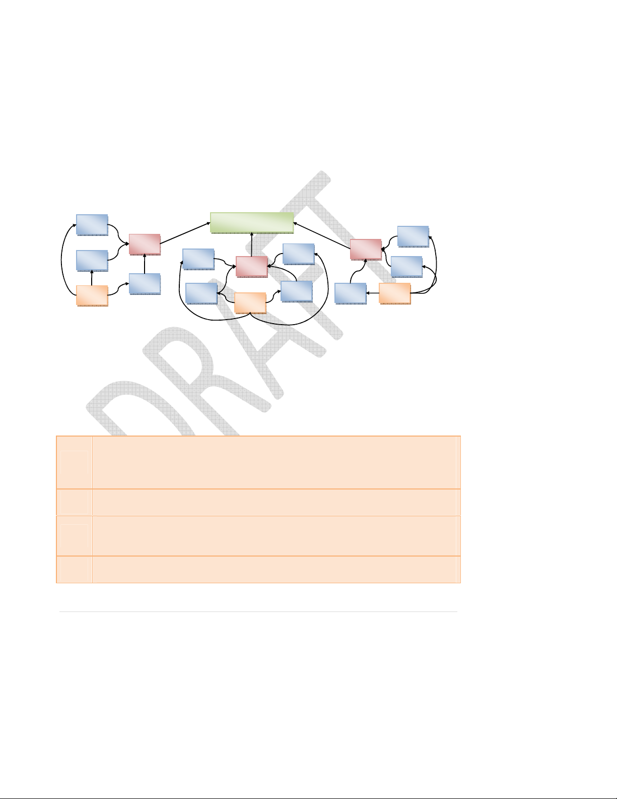
The picture above shows the basic outline of the nGage system. It consists of a network of various devices
that communicate with a Server. The number and disposition of individual elements will vary with each
installation, but following are the basic elements:
Central server consists of software with database and a physical server computer. Typically,
Server
TAG
one server runs on each site and performs all communication functions. The server contains all
the configuration data as well as history of all events from the network. The server may be
connected to one or more BR units.
Bridge is a unit that performs the translation of data between Ethernet and SNAP® network, a
BR
mesh network over which all the wireless devices communicate.
Control Units are adjacent to the dispenser stations and perform two functions: wake up when
CU
a TAG is nearby and issue CU transmission to the BR. Each CU configuration is location specific
within the hospital.
Tag is an RF device worn by an individual. The CU monitors when a person enters the room,
engages the alcohol or soap dispenser, and exits the room.
© 2010-2011 Proventix Systems, Inc. 8
Page 10

Implementation Plan
Establishing and following an implementation plan is essential to the project success. The plan serves as a
primary communication venue between the Proventix and its Client. A detailed Implementation Plan and
checklist is included in the Appendix.
Technical Specifications
FCC/IC Statements
PLEASE NOTE
Electrical equipment should be installed, operated, serviced, and maintained
only by qualified personnel. No responsibility is assumed by Proventix Systems for any
consequences arising out of the use of this material.
Warning: Changes or modifications to this device not expressly approved by Proventix
Systems could void the user’s authority to operate the equipment.
FCC NOTICE
“
NOTE: This equipment has been tested and found to comply with the limits for a Class
B digital device, pursuant to Part 15 of the FCC Rules. These limits are designed to
provide reasonable protection against harmful interference in a residential installation.
This equipment generates, uses, and can radiate radio frequency energy and, if not
installed and used in accordance with the instructions, may cause harmful interference
to radio communications. However, there is no guarantee that interference will not
occur in a particular installation. If this equipment does cause harmful interference to
radio or television reception, which can be determined by turning the equipment off
and on, the user is encouraged to try to correct the interference by one or more of the
following measures:
© 2010-2011 Proventix Systems, Inc. 9
Page 11

• Reorient or relocate the receiving antenna.
• Increase the separation between the equipment and receiver.
• Connect the equipment into an outlet on a circuit different from that to which the
receiver is connected.
• Consult the dealer or an experienced radio/TV technician for help.”
Control Unit RF Exposure Statement
“This equipment complies with FCC radiation exposure limits set forth for an
uncontrolled environment. This equipment should be installed and operated with
minimum distance 20cm between the radiator and your body. This transmitter must not
be co-located or operating in conjunction with any other antenna or transmitter.”
Tag RF Exposure Statement
Not applicable
IC NOTICE
This device complies with Industry Canada licence-exempt RSS standard(s). Operation is
subject to the following two conditions: (1) this device may not cause interference, and
(2) this device must accept any interference, including interference that may cause
undesired operation of the device.
Ce dispositif observe l'Industrie de Canada la norme(s) RSS exempte de licence.
L'opération est soumise aux deux conditions suivantes : (1) ce dispositif ne peut pas
causer l'interférence et (2) ce dispositif doit accepter n'importe quelle interférence, y
compris l'interférence qui peut causer l'opération peu désirée du dispositif.
Under Industry Canada regulations, this radio transmitter may only operate using an
antenna of a type and maximum (or lesser) gain approved for the transmitter by
Industry Canada. To reduce potential radio interference to other users, the antenna
type and its gain should be so chosen that the equivalent isotropically radiated power
(e.i.r.p.) is not more than that necessary for successful communication.
© 2010-2011 Proventix Systems, Inc. 10
Page 12

Hardware
nGage Client Server
• Provide power and Ethernet
• Static IP address
• Needs remote access
• Run MySQL Server database
• Needs Internet Access
• Runs Proventix HL7 Listener
SNAP® network
• IEEE protocol 802.15.4
• 16 selectable channels in a frequency range of 2400-2480 MHz
• Uses two channels: one for the tag and a second for the control unit
Control Units (CU)
• 120Vac 0.1A or 8-16Vdc 0.2A
• Installed adjacent to soap and hand sanitizer dispensers in each room or hallway
Bridge Unit
• Provide power and Ethernet
• 120Vac 0.2A
• Installed in local area to communicate with the CU units
o Typically 1 per floor depending on configuration and layout of hospital
System Architecture
The system architecture accessing the databases consists of the database server and the application
server. The purpose of this section is to outline the architectural infrastructure of the system.
© 2010-2011 Proventix Systems, Inc. 11
Page 13

nGage Client Server Application
• The application collects the data from the SNAP® network of detection devices and constructs
a comprehensive history of events.
• The configuration component of the application maintains locations, tags, persons, messaging
and full application management detail.
• The application is designed to operate without intervention and, at the same time, allow
immediate actions by the operator.
Technology
• The application is written in Microsoft .NET framework.
• The secure SSL infrastructure supports user authentication with user specific capabilitys
set. User type determines what features can be accessed.
• Database server is MySQL Server. The server is accessed using MySQLClient drivers for .NET.
Network
• The nGage system consists of the detection units that capture the information, connectivity
software and hardware, and the server that receives all data, computes the information
database, and provides both configuration and analysis access to the information.
• The CU Units gather information about dispensing and entry/exit of the control areas. This
information is sent to a server using SNAP® network via Bridge unit. The Bridge unit
translates the SNAP® to Ethernet and provides data buffering.
• Trial - The Client Server Application runs the nGage Server application and MySQL Database
server behind the firewall. This provides access for operation and configuration messaging.
• Long-Term – To be discussed with facility.
nGage Web Server
The server software manages the data gathering, interpreting, and presenting. Major parts of
the system are depicted below:
© 2010-2011 Proventix Systems, Inc. 12
Page 14
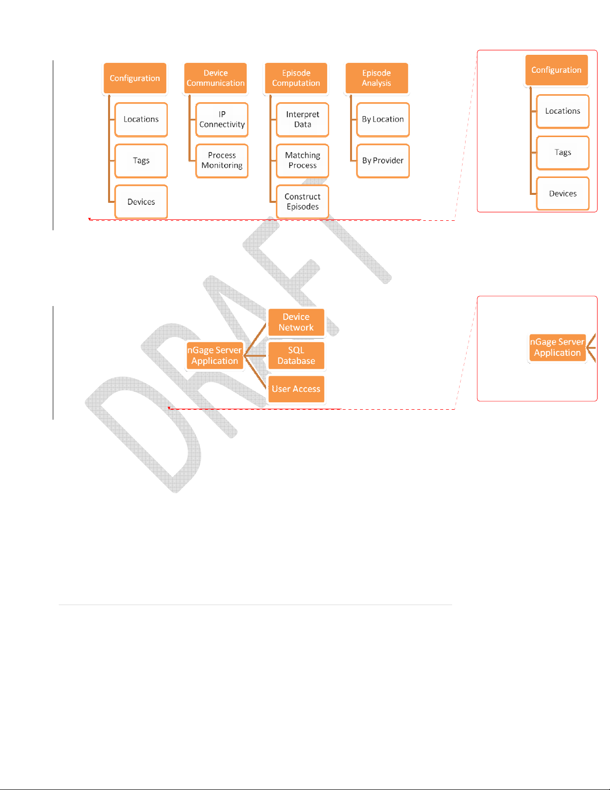
The major elements of the system are depicted below:
Infrastructure
The nGage system consists of multiple components. The components should be organized to ensure
highest quality of resulting data. The hardware components, connectivity software, and server software
represent the infrastructure of the installation.
Procure & Prepare
• All requisite equipment procured and prepared for installation.
• Prepare all requisite items and order any parts to ensure availability of complete list.
© 2010-2011 Proventix Systems, Inc. 13
Page 15

• Prepare all units and perform testing, prepare for installation and procure all
equipment.
nGage Client Server
Install the server and establish the network configuration. See nGage Client Server definitions
in this document for more details.
• Prepare the server system and load all system software.
• Load the nGage client server software, database, and verify function.
Connect to Internet
Establish Internet connectivity to the network (using BR units) and from the server to the
external access (SSL, firewall, etc.) See nGage Client Server definitions in this document for
more details.
• Install the server hardware and BR hardware at client’s site and configure for remote
access.
• Validate the connection to the Bridge unit and configure the IP addresses and port
numbers.
Install Components
Install all CU and BR units as defined in the site plan and verify all are properly identified by the
SNAP® Network.
• Install the CU units in their respective locations.
• Verify that SNAP® connectivity is acquired for each CU.
• Resolve any issues.
Client Data Extraction for Tracking and Reporting
• HL7
o ADT
• HIS Census
o Identify a HIS inpatient census report that contains the data elements below.
o Send a sample report to Proventix for content and structure confirmation.
o Schedule report 4 times daily (e.g. 4am, 10am, 4pm, & 10pm) and send to
d:\nGage_data on the Proventix nGage server.
© 2010-2011 Proventix Systems, Inc. 14
Page 16

o The census report is used with ADT to build an accurate facility census and patient
movement model. ADT alone does not allow us to do this.
• HIS Census File Specification
o The HIS census file contains the roster of the hospital patients at a particular date and
time.
o Each row describes one patient
o All fields should be pipe ‘|’ delimited
Field
Field Description Required
Site
Census date
Census time
Report date
MR number
Account number Unique number for this patient’s current admission
Admission date
Location
Room – Bed
Patient name
Patient DOB
Patient age
Diagnosis
MD
Client or hospital site ID. This identifies an individual hospital
Format: MM/DD/YYYY [09/03/2004]
HH:MM:SS Military time
Date that the report was generated. Format: MM/DD/YYYY [09/03/2004]
Medical record number
Format: MM/DD/YYYY [09/03/2004]
Nursing station or ward [4W]
Room number –Bed Number
Last name, first name or last name, first name, middle initial
Date of birth
[60 or 6M]
Attending physician name
Yes
Yes
Yes
Yes
Yes
No
Yes
Yes
Yes
Yes
Yes
No
Yes
Yes
Des
Example: (this example shows a patient record without Account number and Patient age – both are
optional fields)
HOSPA|1/22/2004|0:00:00|1/22/2004|000123456||1/21/2004|4W|8-A|Doe, John, M |
|5/22/1938||INCONTINENCE|Cure, All, MD| cription
• Catalogs (if available)
o Facility location catalog
HL7 Specifications
Our protocol follows the default HL7 standard. We listen, on the configured port, for HL7 (2.2 or 2.3)
messages, with the following standard HL7 wrapper:
<0x0B>data<0x1C><0x0D>
Where “data” is a stream of HL7 data, typically ADT messages.
The data content, including the format of the HL7 messages, is not validated by the listener.
© 2010-2011 Proventix Systems, Inc. 15
Page 17

When we receive data in this wrapper, we immediately send back an acknowledgment in the following
format:
0b 4d 53 48 7c 5e 7e 5c 26 7c 7c 7c 7c 7c 7c 7c .MSH|^ ~\&|||||||
41 43 4b 7c 47 7c 47 7c 32 2e 33 0d 4d 53 41 7c ACK|G| G|2.3.MSA|
41 41 7c 46 0d 1c 0d AA|F.. .
No other wrapper / ACK / NAK is expected.
Below is our preferred HL7 file layout (v2.3). Versions 2.1 and 2.2 layouts are available upon request. If
your default HL7 file layout differs from this, please let us know. We can accept data in many different
formats, as long as the required fields are sent. (minimum desired ADT trigger events are listed in FAQ
section at the end of this document).
ADT
2.3 MSH_MessageControlId MSH/MessageControlID
2.3 MSH_MessageDateTime_Day MSH/DateTimeOfMessage/Time/Day
2.3 MSH_MessageDateTime_Hours MSH/DateTimeOfMessage/Time/Hours
2.3 MSH_MessageDateTime_Minutes MSH/DateTimeOfMessage/Time/Minutes
2.3 MSH_MessageDateTime_Month MSH/DateTimeOfMessage/Time/Month
2.3 MSH_MessageDateTime_Year MSH/DateTimeOfMessage/Time/Year
2.3 MSH_SendingApplication MSH/SendingApplication/NamespaceID
2.3 MSH_SendingFacility MSH/SendingFacility/NamespaceID
2.3 AccountNumber PID/PatientAccountNumber/IDNumber
2.3 AdmissionDateTime_Day PV1/AdmitDateTime/Time/Day
2.3 AdmissionDateTime_Hours PV1/AdmitDateTime/Time/Hours
2.3 AdmissionDateTime_Minutes PV1/AdmitDateTime/Time/Minutes
2.3 AdmissionDateTime_Month PV1/AdmitDateTime/Time/Month
2.3 AdmissionDateTime_Year PV1/AdmitDateTime/Time/Year
2.3 AdmittingDiagnosisCode DG1[0]/DiagnosisCodingMethod
2.3 AdmittingDiagnosisDescription DG1[0]/DiagnosisDescription
2.3 AssigningFacility PID/InternalPatientID/AssigningFacility
2.3 AttendingDoctor_FirstName PV1/AttendingDoctor[0]/GivenName
2.3 AttendingDoctor_LastName PV1/AttendingDoctor[0]/FamilyName
2.3 BirthDate_Day PID/DateTimeOfBirth/Time/Day
2.3 BirthDate_Month PID/DateTimeOfBirth/Time/Month
2.3 BirthDate_Year PID/DateTimeOfBirth/Time/Year
2.3 PatientAddress_Address1 PID/PatientAddress[0]/StreetAddress
2.3 PatientAddress_Address2 PID/PatientAddress[0]/OtherDesignation
2.3 PatientAddress_City PID/PatientAddress[0]/City
2.3 PatientAddress_State PID/PatientAddress[0]/StateOrProvince
2.3 PatientAddress_ZipCode PID/PatientAddress[0]/ZipOrPostalCode
2.3 PatientBed PV1/AssignedPatientLocation/Bed
2.3 PatientClass PV1/PatientClass
2.3 PatientFirstName PID/PatientName[0]/GivenName
2.3 PatientHomePhone PID/HomePhoneNumber[0]/PhoneNumberString
2.3 PatientId (Medical Record Number) PID/PatientIdentifierList[0]/IDNumber
2.3 PatientLastName PID/PatientName[0]/FamilyName
2.3 PatientLocation PV1/AssignedPatientLocation/PointOfCare
2.3 PatientRoom PV1/AssignedPatientLocation/Room
2.3 PatientType PV1/PatientType
Site Planning
The nGage system monitors the location of a person at a given time. The CU (Control Unit) detects a
person’s position. A specific Tag associated with each individual detects who is near the CU range.
Mapping of all the devices must be clearly understood and accurate.
© 2010-2011 Proventix Systems, Inc. 16
Page 18
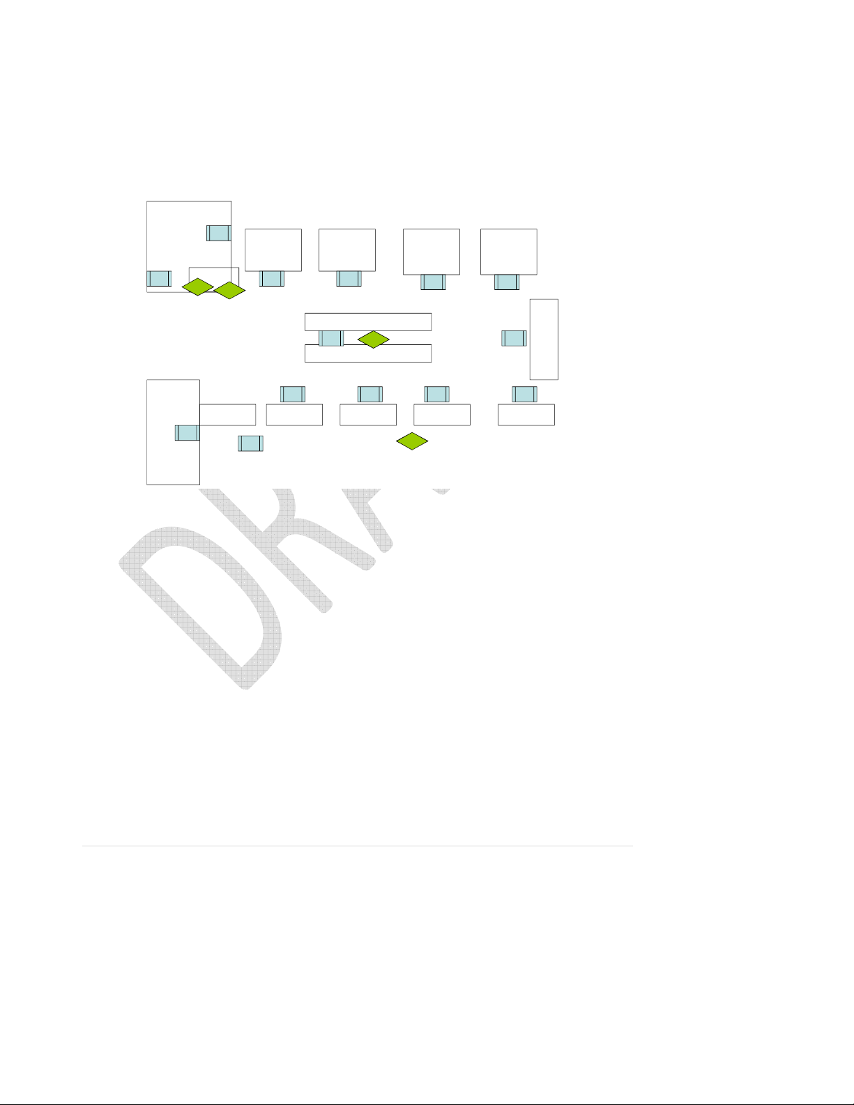
Floor Plan
Obtain the floor plan and walk through the facility recording the location of units (CU and BR).
Note the power and Internet connection availability.
Emergency Room
ER Entrance – Waiting
Room and Check-In
CC2
20002
Physician Tag#
Dr. Mickey - 2201
Dr. Nobetter - 2202
Dr.Getbetter- 2203
Hall Way
Entrance to
Hospital
CC1
CC3
EE4
20013
CC1
20001
Public
Restrooms
20029
Utility Room
Room 5 Room 6
20003
CC4
Prefix “1001”
Prefix “2001”
20003
Room 4 Room 3 Room 2 Room 1
20028
20004
CC1CC1
Nursing Station Desk
20012
Hand Washing Sink and Cabinets
20011
CC1
Hand Cleansing Dispenser
Control Unit
20027
CC1 CC2
20010
CC1 CC1
20009 20008
Prefix “1001”
CC1 CC1
Hand Washing Dispenser
Control Unit
Room 8Room 7
2000620005
Room
9
EE1
20007
CC1
CC1
The example above shows the sample coding of the locations. Note that the floor plan does not
have to be to scale as long as components and their locations are properly labeled.
Assign Locations
Finalize the plan of locations, prepare list of any electrical or mechanical work needed to
prepare the site. As indicated above, each location must establish type of location, name of
location, power supply needs and placement of the unit.
• Determine whether any special wiring is needed.
• Determine where the BR unit will be positioned to ensure connectivity and appropriate
location.
• Determine the range limits of the CU units.
© 2010-2011 Proventix Systems, Inc. 17
Page 19

Approvals
The proposed setup will be reviewed to ensure the unit position provides a functional
environment. Compliance with hospital and regulatory policies will also be reviewed. Any
discrepancies will be corrected.
Coding and Validation
The results of site planning will be coded into the Server software to allow correct recording of person’s
to a location. This section focuses on coding of devices to associate them with locations and persons.
Code Configuration
• Prepare configuration on the Server.
• Code the Site, Region, and Departments as needed.
• Using Site Plan, code all locations and assign to the proper Building, Floor, Room, and
individual locations.
• Code all CU units and associate with the individual locations.
• Code the Tags into the tag master, code staff into the person master, and associate the
persons with the Tags.
• Verify all BR units in the connection list with proper IP addresses.
Validate Configuration
Validate the proper coding by separate audit. This requires independent review of information
and all against discrepancy.
Perform Proventix Test Run
Perform several test runs, record results, and compare with the system recorded information.
The test run requires that the sample tags go through the motions at all locations and the
information recorded at the Server is validated.
Perform Client Data Extraction Test Run
HL7 – ADT and HIS Census
© 2010-2011 Proventix Systems, Inc. 18
Page 20

Standard Operating Procedures (SOPs)
The nGage system is designed to function for the most part automatically. During its operation, the
server periodically polls the devices, stores the data, and generates information. The purpose of this
section is to develop SOPs to support its operation.
Changing Tags
This procedure describes the steps to assign or un-assign a person’s tag. This also involves
training the staff.
Moving CUs
This process will be performed when the unit is replaced or moved. This also involves training
the appropriate staff.
Monitoring Operation
This describes periodic monitoring. Note: Proventix support monitors the system and will notify
the Client’s staff of any specific events. This includes steps to take when to restart or stop the
system for any reason.
Support Procedures
The support procedures ensure effective communication between Proventix and the Client. The Proventix
technical and client support is critical part of the system operation.
Time of Operations
Proventix office hours are Monday-Friday 8am -5pm Central.
Contact Numbers
Proventix main office number is (205) 383-1156. Clinical support is (205) 332-1750 or (205) 588-5523.
Technical support is (205) 383-3654 or (205) 332-1725.
© 2010-2011 Proventix Systems, Inc. 19
Page 21

nGage Client Server
The server hardware and software contains all configuration data, all processes that assemble and
interpret information, and all communication within the nGage network and outside Internet.
Requisite Functions
The server performs the following services:
• nGage server software is a windows application designed to manage all data management and
collection functions of the system. The application operates on the windows .net framework.
• nGage server hardware needs to be accessible for technical support using Remote Desktop with
the appropriate VPN access security.
• nGage server needs to be connected to all BR (Bridge Units) via HTTP port 8080.
Server Hardware
The requirements for hardware are current expectations only and will evolve through testing and client
experience. A Virtual Server is preferred with Windows 2008 R2 and 40GB of Disk Space.
Processor 2 - 4GHz, dual core or faster
Memory 4GB minimum
Disk Space 40GB optimally (only one week of data is retained on server)
Network Adapter 10/100 or faster
Optical Drive For example: 16x DVD+/-RW Drive (not necessary)
Chassis Type Recommend virtual PC but 1U or Desktop PC can be utilized
© 2010-2011 Proventix Systems, Inc. 20
Page 22
Preferred
Windows
Server 2008 R2 Standard (License provided by Proventix)
VPN / Remote
Server Software
The requirements for software are described below.
OS
Server
Desktop
nGage Server
Software
Other OS must be approved by Proventix
Requires static IP address and configuration of the internal network to allow
access. Also needs internet access.
To provide access in configuring and managing the software.
Proventix will install
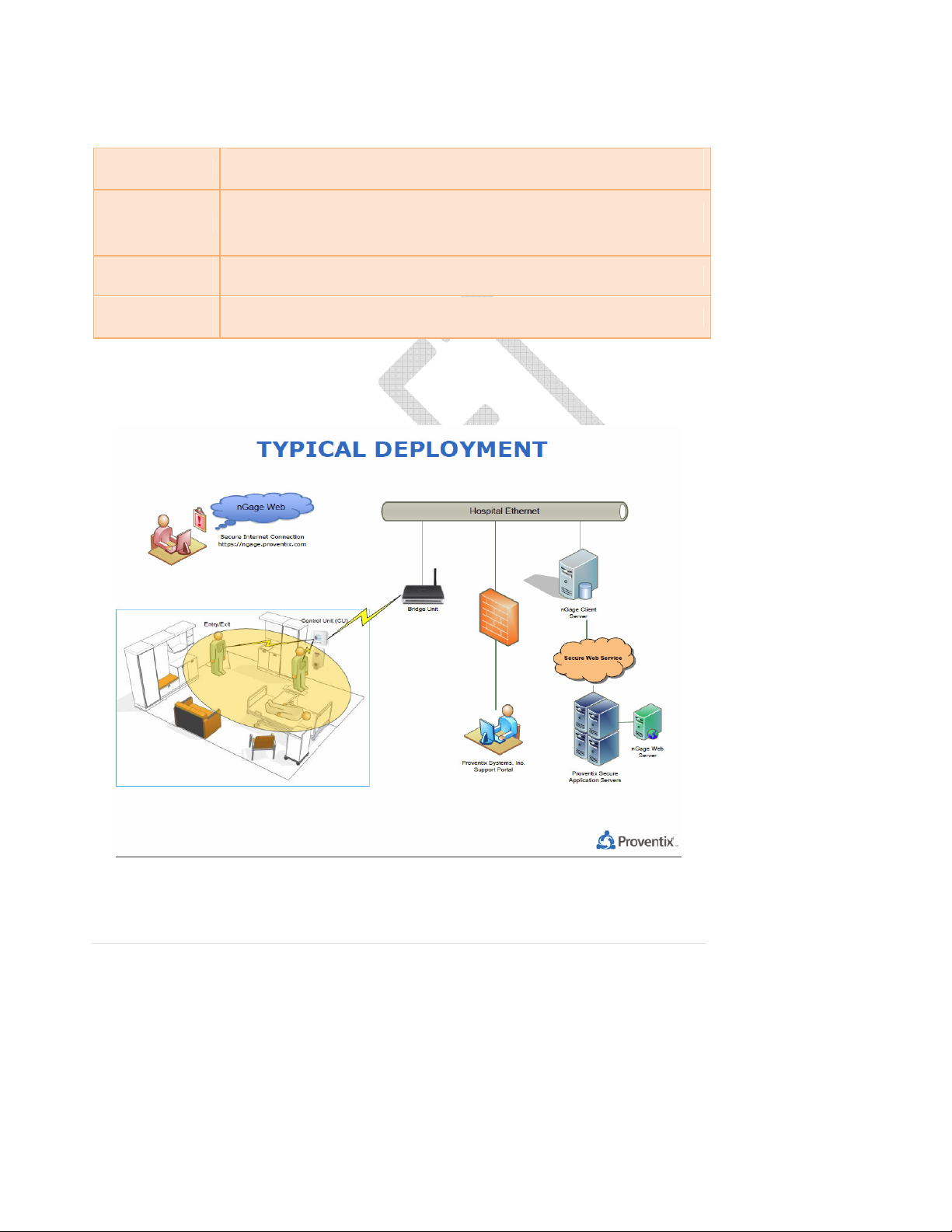
Network Diagram
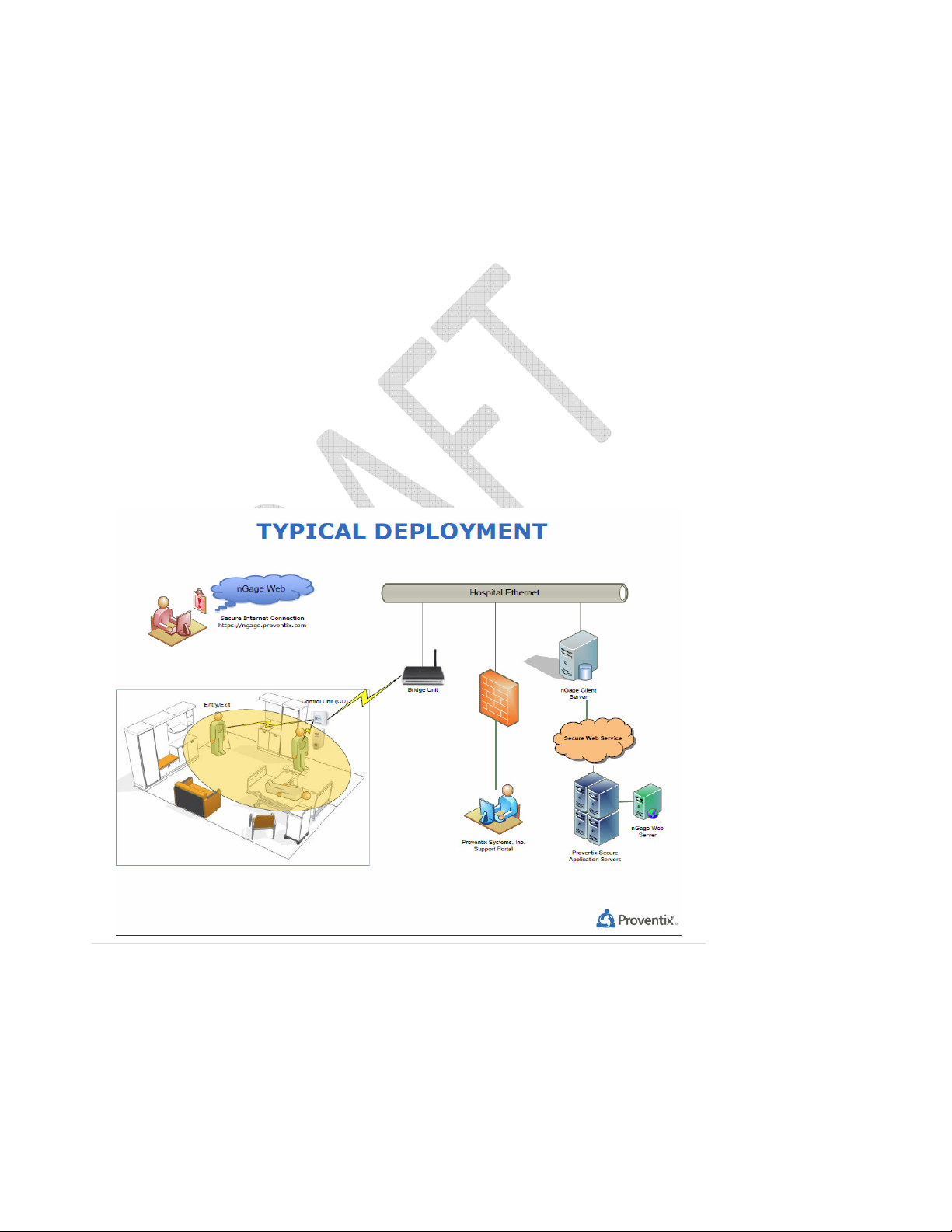
The image below shows the layout of the network.
© 2010-2011 Proventix Systems, Inc. 21
Page 23
The actual configuration will wary depending on the physical layout.
• There is one Site Server per location (hospital/facility).
• The Site Server handles one or more Bridge units. The Bridge translates information between
SNAP® units and Site Server.
• The Bridge handles a SNAP® network consisting of Tags, Control Units (for detection of hand
washing and of room entry and exit).
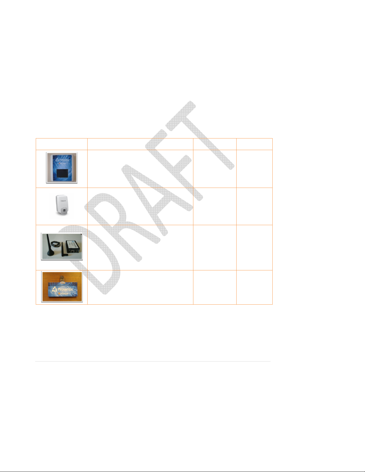
Network Elements
The requirements for the individual nGage-specific devices are in the table below:
Icon Description Size/Weight Power
Control Unit: located near the dispenser, it
detects a person operating the dispenser as
well as entry and exit into room.
4” x 4” x 1.5”
(approximate)
Weight
5.6 oz
8-16VDC at
0.2A OR
110VAC at
0.1A
Dispenser: The nGage system works with
any dispenser. The Control Unit must be
mounted within 4” of the place where the
hands are rubbed.
NA NA
Bridge Unit: located within range (200’ or
more* of the nearest other unit.
* the range may be affected by other objects
4” x 4” x 1.5”
(approximate)
Weight
5.6 oz
120VAC at
0.2A
and will vary.
1.75” x 3.5” x .4”
Tag: assigned to the person and is worn by
the person for proper detection.
(approximate)
Weight
1.1 oz
Battery
CR2450 3VDC
© 2010-2011 Proventix Systems, Inc. 22
Page 24

Appendix
Implementation Checklist
Description
Step
1 Project Staffing
Prepare Contact Sheet for the project. This
1.1
includes staff from Proventix and the Client
required for carrying out the tasks.
1.2 Obtain approval from Proventix and Client.
2 Initial Project Meeting
Present the Implementation Plan to the staff
2.1
involved in the project and ensure that
everyone understands.
Prepare a preliminary schedule by assigning
2.2
the responsibilities and dates.
Discuss the communication methodology and
2.3
the types of documents available.
3 Site Planning
Obtain the floor plan and walk through the
facility recording the location of units (CU) and
3.1
Note the power and internet connection
availability.
Identify Ethernet connection for bridge unit
3.2
(BU)
Finalize the plan of locations, prepare list of
3.3
any electrical or mechanical work needed to
prepare the site.
3.4 Procure approvals
4 Infrastructure
Prepare all units and perform testing, prepare
4.1
for installation and procure all equipment.
Install the server hardware and make it
4.2
available to establish the configuration.
Establish internet connectivity to the network
4.3
(using BR units) and from the server to the
Person
Completed
Date
Completed
Completion
Notes
© 2010-2011 Proventix Systems, Inc. 23
Page 25

external access (SSL, firewall, etc.)
Install all CU and BR units as defined in the site
4.3
plan and verify all are properly identified by
the SNAP® Network.
5 Coding and Validation
Code all locations, tags, and persons. Associate
5.1
the persons with tags and CU with locations.
5.2 Validate the proper coding by separate audit.
Perform several test runs, record results, and
5.3
compare with the system recorded
information.
6 Standard Operating Procedures
6.1 Prepare SOP’s and approve with Client.
7 Startup
Reset the system for startup and initiate
7.1
startup monitoring.
© 2010-2011 Proventix Systems, Inc. 24
Page 26

Frequently Asked Questions
Where will the application software reside (locally on a site server or, instead, remotely on a
Proventix server)?
The nGage Server will reside on the client’s machine. The nGage Web application will reside on a remote
Proventix server.
The nGage Server (Client-Side)
• Monitor Bridge Units.
• Get Unit transactions from Bridge Units.
• Store Person and Control Unit Messages and Names.
• Send messages to Control Units.
• Send Unit transactions and server messages to remote Proventix server.
• Receive Person and Control Unit messages and Name updates from Proventix server.
The Proventix Server (Remote)
• Uploads unit transactions and server messages into Database server.
• Provide Web interface for reporting, monitoring, and inventory.
• Sends message and name updates to individual client nGage servers.
Where will the database software reside (it appears this will be local)?
The main database will reside on a remote Proventix server. The raw archive database that resides on
the client server only retains one week of data
Are the application software and the database software, in fact, separate programs?
Yes, the application software is written in Microsoft .NET and the database software is written in MySQL
database.
Virtual Server requirements:
• OS: Windows Server 2008 R2 Standard – license can be provided by Proventix.
Installed applications: Disk Space Usage
Tera-Term 4.66 (8M)
Phython 2.5 (55M)
Phython Crypto Cipher & Phython Windows 32 bit.
MySQL 5.1 (138M)
MySQL GUI Tools 5.0 (38M)
MySQL Data Provider
Synapse Portal Software. (47M)
Proventix Snap Server Application (29M)
Proventix HIS listener (9M)
© 2010-2011 Proventix Systems, Inc. 25
Page 27
Proventix HIS Census Processer (1M)
Proventix Client Data Server (1M)
Proventix Total : (326M)
With OS: (24G)
Database growth essentially non-existent. As only a weeks' worth of data is archived on the client server machine.
40G of disk space is desired which would include the OS.
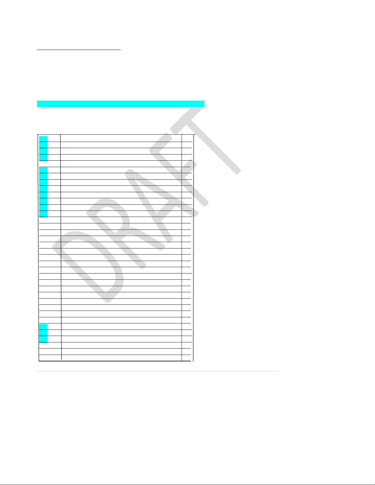
Desired ADT trigger events needed:
A01, A02, A03, A04, A06, A07, A08, A09, A10, A11, A12, A13, A23, A32, A33, A34
ADT Trigger Events desired
V
ALUE DESCR IPTION
A01 Admit a patient Yes
A02 Transfer a patient Yes
A03 Discharge a patient Yes
A04 Register a patient Yes
A05 Preadmit a patient No
A06 Transfer an outpatient to inpatient Yes
A07 Transfer an inpatient to outpatient Yes
A08 Update patient information Yes
A09 Patient departing Yes
A10 Patient arriving Yes
A11 Cancel admit Yes
A12 Cancel transfer Yes
A13 Cancel discharge Yes
A14 Pending admit No
A15 Pending transfer No
A16 Pending discharge No
A17 Swap patients No
A18 Merge patient info - NO LONGER USED No
A19 Patient query No
A21 Patient goes on a “leave of absence” No
A22 Patient returns from a “leave of absence” No
A23 Delete a patient record Yes
A24 Link Patient Information No
A25 Cancel pending discharge No
A26 Cancel pending transfer No
A27 Cancel pending admit No
A28 Add person information No
A29 Delete person information No
A30 Merge person information No
A31 Update person information No
A32 Cancel patient arriving Yes
A33 Cancel patient departing Yes
A34 Merge patient information -patient ID only Yes
A35 Merge patient information - account number only No
A36 Merge patient information - patient ID & account # No
A37 Unlink patient information No
REQUI RED
© 2010-2011 Proventix Systems, Inc. 26
Page 28

© 2010-2011 Proventix Systems, Inc. 27
 Loading...