

Page 1
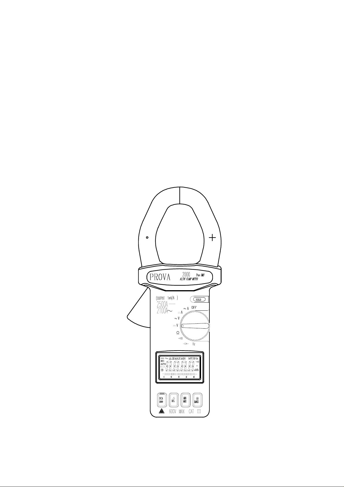
DC/AC CLAMP METER
ISO-TECH 2000
USERS MANUAL
Page 2

Page 3
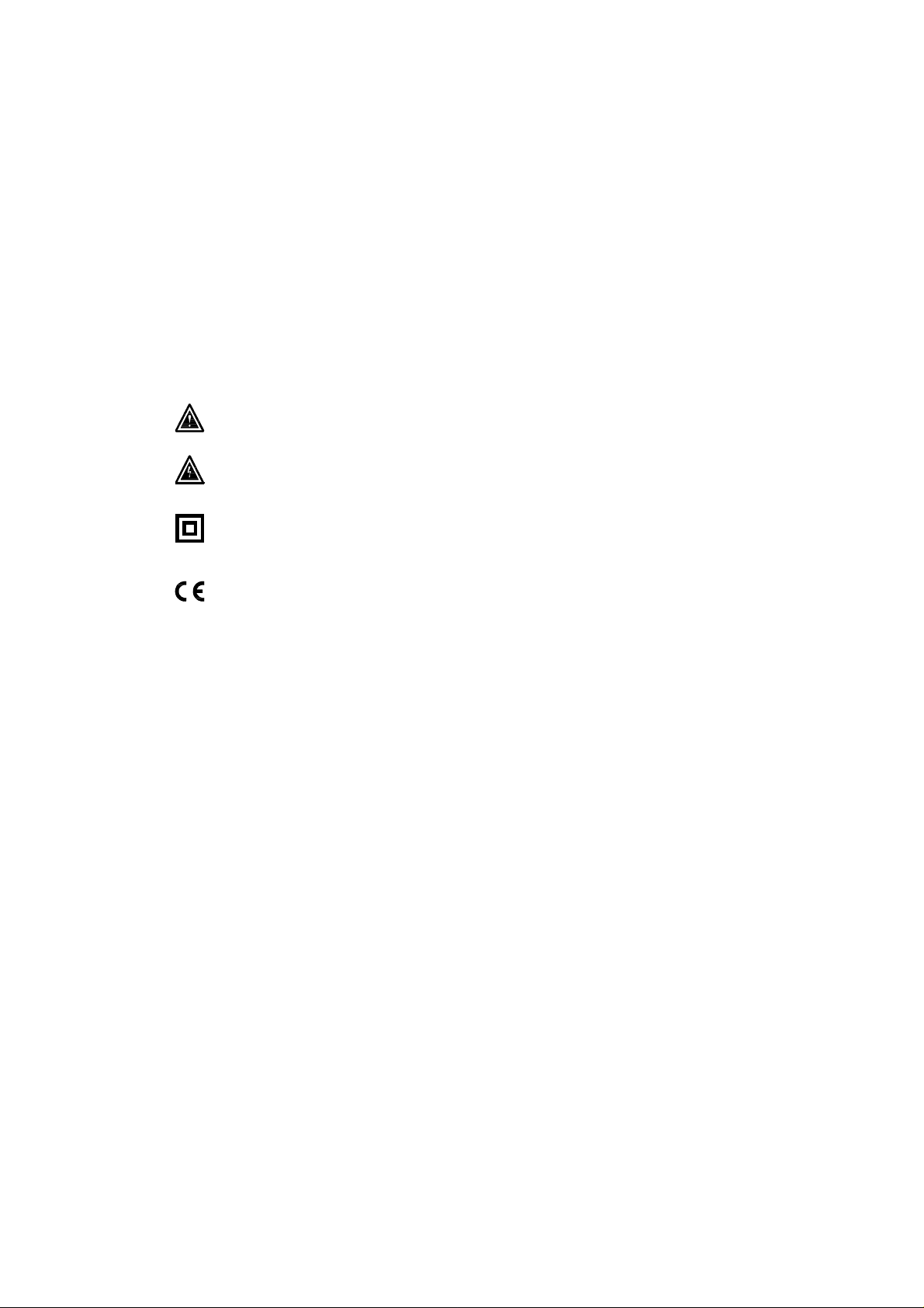
Warnings and Safety symbo ls:
Caution, refer to this manual before using the meter.
Dangerous voltages.
Meter is protected throughout by double insulation or
reinforced insulation.
Comply with IEC1010-1
When servicing, use only specified replacement
parts.
1
Page 4

TABLE OF CONTENTS
1.Features............................................................................................................... 1
2. Panel Description............................................................................................... 2
3.Operation Instructions......................................................................................... 5
3.1. DC/AC Current Measurements.................................................................. 5
3.2. DC/AC Voltage Measurements................................................................. 7
3.3. Resistance Measurement............................................................................ 8
3.4. Continuity Measurement............................................................................ 8
3.5. Change from Auto-range Mode to Manual Mode...................................... 9
3.6. Relative Reading Measurements................................................................ 9
3.7. Holding the LCD Reading......................................................................... 9
3.8. Finding the MAX/MIN Value................................................................... 9
4.Specifications..................................................................................................... 10
5.Battery Replacement.......................................................................................... 13
6. Maintenance & Cleaning................................................................................... 14
2
Page 5

1.Features1.Features
1. Accurate DC/AC digital clamp meter for current measurement.
2. DC 2500A, AC 2100A (True RMS ).
3. φ55 mm diameter jaw.
4. One touch zero for DCA adjustment.
5. Auto-range for A, V, amd Ω.
6. Large 3 3/4 digits LCD
6. Fast bargraph display (20 times/sec.) for transient observation.
7. Continuity with buzzer.
8. Max/Min and Data Ho ld functions.
9. 600V overload protection for ohm measurement.
10. Easy single rotary switch for any function selection.
3
Page 6
2. Panel Description. Panel Description
4
Page 7

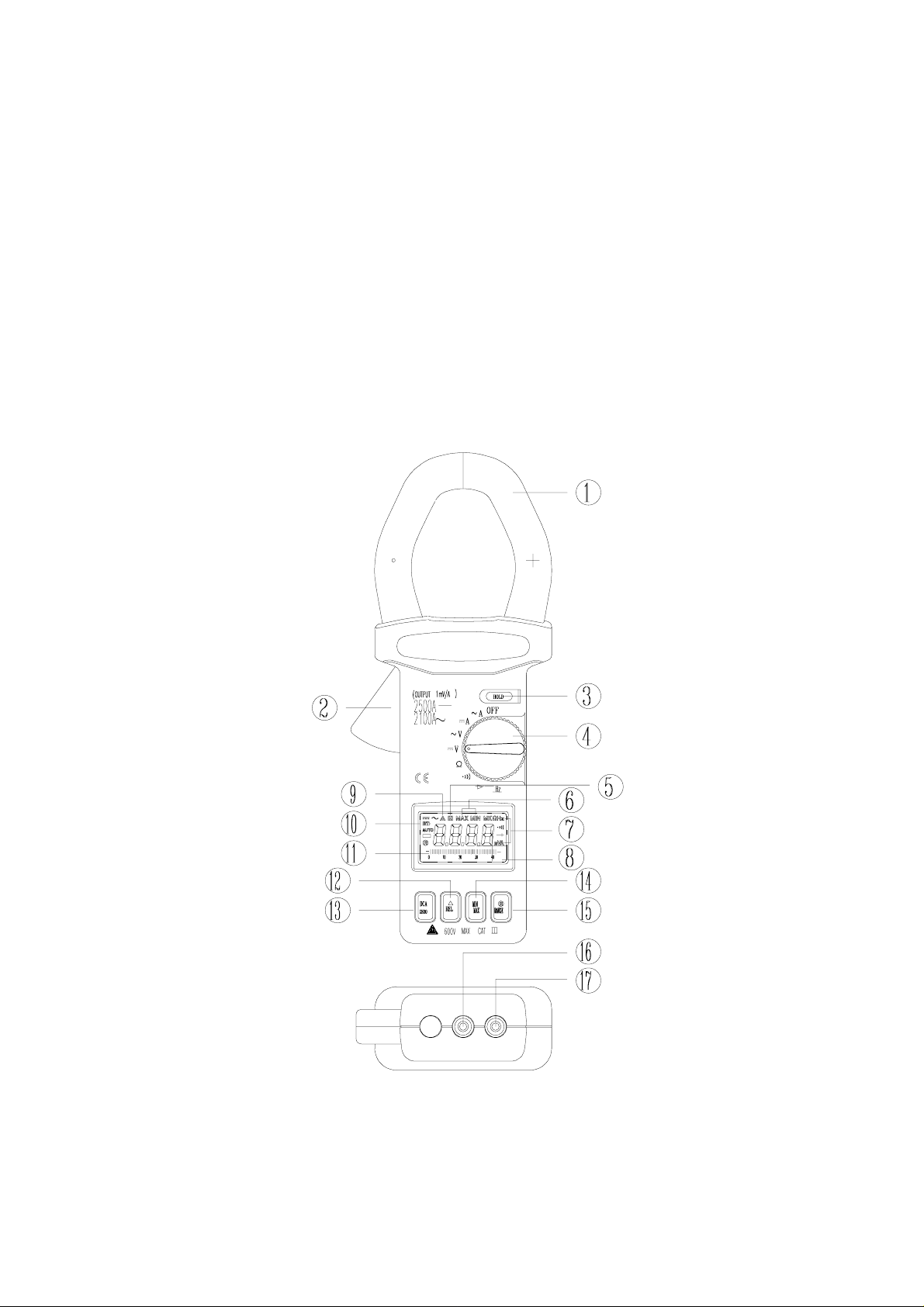
1. Transformer Jaw
This is used to pick up a current signal. To measure DC/AC current, a conductor
must be enclosed by the jaws.
2. Transformer Trigger
This is used to open the jaws.
3. Data Hold Button
Press this button to hold the current reading in the LCD display. Press it again to
release the HOLD function .
4. Function Selection and On/Off Switch
This is used to select the desired function, such as DCA, ACA, DCV, ACV, Hz, Ohm
and Continuity.
5. Data Hold Symbol
Once the hold button is pressed, this symbol appears in the LCD display.
6. Max/Min Hold Symbol
Once the max/min button is pressed, either MAX or MIN shall be displayed on LCD
7. Units Symbols
Once a function is selected, the corresponding unit (V, Ω, A, or Hz) shall be
displayed on LCD.
8. LCD
This is a 3 3/4 digit Liquid Crystal Display with maximum indication of 3999.
Function symbols, units, bargraph, sign, decimal points, low battery symbols,
max/min symbols, and zero symbol are included.
9. Zero/Relative Symbol
When this symbol appears, it means a reference value has been subtracted from the
actual reading. The reading shown is an offseted value. Press and hold the zero
button for 2 seconds to disable this function.
10. Low Battery Symbol
When this symbol appears, it indicates that the battery voltage has dropped below the
minimum required voltage. Refer to Section V for battery replacement.
11. Analogue Bargraph
The Bargraph has forty segments. It displays segments proportional to the actual
reading. Each segment represent ten counts.
5
Page 8

12. Relative Button
Once this button is pressed, the current reading shall be set to zero and be used as a
zero reference value for all other subsequent measurement. The function can also be
used to offset readings caused by the residual magnetism remaining in the core for
DC current measurements. Once this button is pressed, the clamp meter will change
to manual mode instead of auto-range mode. The Relative function will be disabled
if Max/Min function is enable d.
13 DCA ZERO button
This button is used for DCA ZERO function. To zero the DCA residual value, press
this button until the LCD displays zero. If the DCA ZERO button is used to zero a
DCA value, the clamp meter is still in auto-range mode. ( It is different from the the
relative button which forces the clamp meter change to manual mode.)
14. Max/Min Hold Button
This button is used to enable the maximum or minimum value to be displayed and
updated during measurement. Press it once and the minimum value shall be
displayed and updated. Press it again and the maximum value shall be displayed and
updated. Press it again (the third push) and the clamp meter returns to normal
measurement mode. The Zero function will be disabled if MAX/MIN is enabled.
15. RANGE button
Once the button is pressed, the clamp meter goes into manual mode. To select the
desired range, press and release the button once. To return to the autorange mode,
press and hold the button for more than 2 seconds.
16.COMTerminal
This terminal is used as common reference input.
17.VΩ Input Terminal
This terminal is used as an input for voltage, ohm/continuity, or frequency
measurements.
6
Page 9
3.Operation Instructions.Operation Instructions
3.1. DC/AC Current Measurements
WARNING
Make sure that all the test leads are disconnected from the meter’s terminals for
current measurement.
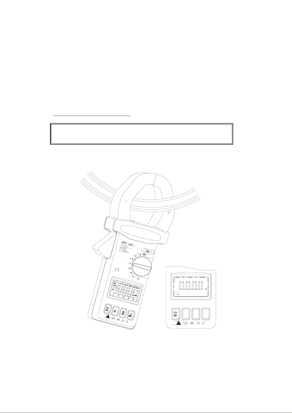
3.1.1. DC Current
7
Page 10
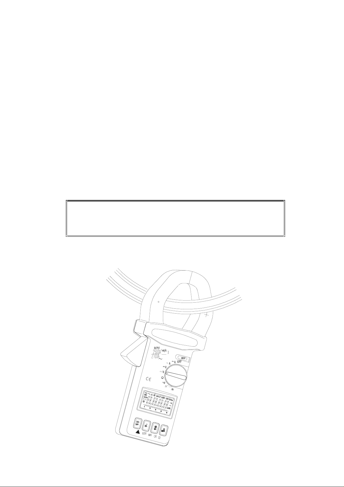
a. Set the rotary switch at DCA.
b. Push and hold the DCA ZERO button until the reading shows zero.
c. Press the trigger to open the jaws and fully enclose the conductor to be measured.
No air gap is allowed between the two half jaws.
d. The clamp meter will automatically select the appropriate range. If the user wants
to select a range manually, press the range button before p ressing the DCA ZERO
button.
e. Read the measured value from the LCD display.
Note
There are two ways to zero the DCA residual value. Use the DCA zero button
and the clamp meter is in auto-range mode. Use the REL button and the clamp
meter will change to manual mode for DCA measurement.
3.1.2. AC Current
8
Page 11
a. Set the rotary switch at ACA.
b. In AC current measurement, ZERO is not needed. Do not press DCA ZERO button.
c. Press the trigger to open the jaw and fully enclose the conductor to be measured. No
air gap is allowed between the two half jaws.
d. The clamp meter will automatically select proper range. If users want to select
range, press the range button before pressing the DCA ZERO button.
e. Read the measured value from the LCD display.
9
Page 12
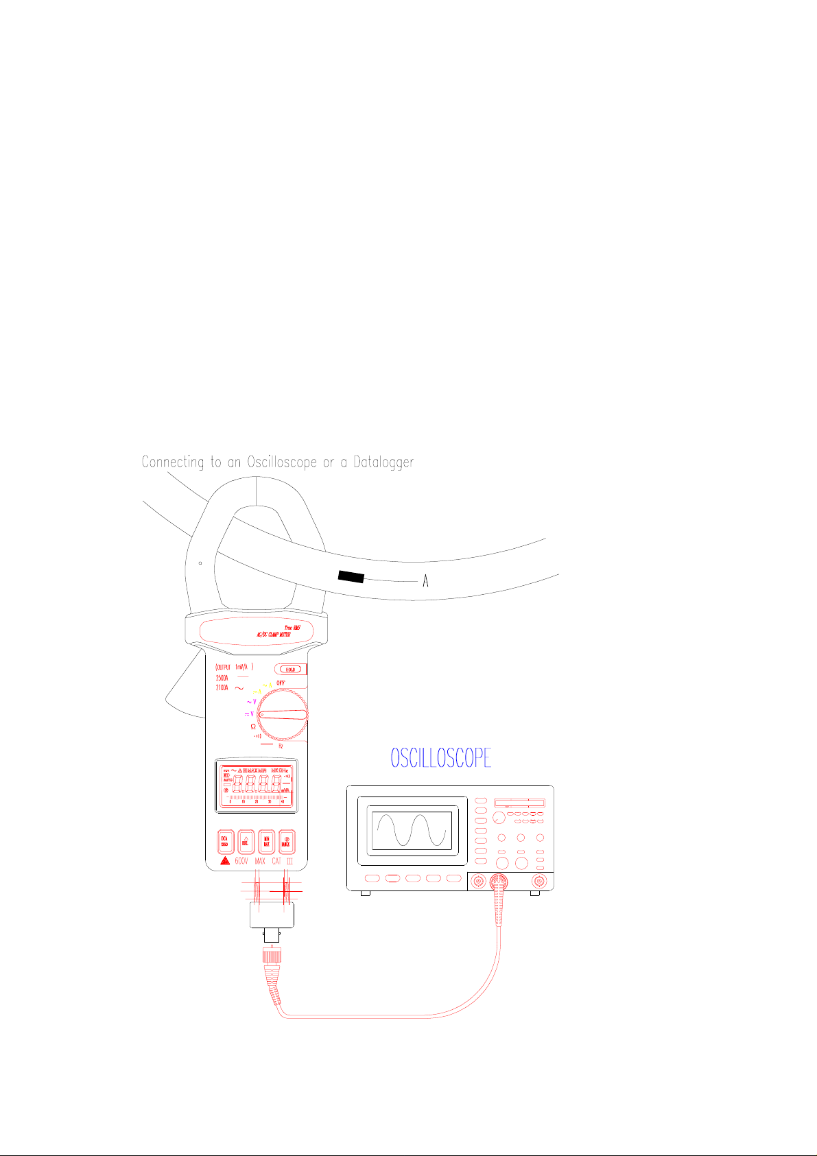
a. Set the rotary switch at ACA or DCA
b. Analog signal is output from the bottom terminals at the same time. The output is
proportional to the current measured (1mV/A).
c. The red terminal is the positive while the black is the negative of the signal.
d. Connect these two terminals to an oscilloscope or a datalogger, users can o bserve the
current wave form or do the long term data recording.
3.2. DC/AC Voltage Measurements.
TEST EQUIPMENT RISK ASSESSMENT (UK RECOMMENDAT I ON)
Users of this equipment and/or their employers are reminded that Health and Safety
legislation requires them to carry out valid risk assessments of all electrical work so as to
identify potential sources of electrical danger and risk of electrical injury such as from
inadvertent short circuits. Where assessments show that the risk is significant then the use
of fused test leads constructed in accordance with the HSE note GS38 “Electrical Test
Equipment for use by Electricians” should be used.
WARNING
Maximum input for DC V is 1000, and for AC V is 750. Do not attempt to take any
voltage measurement that exceeds the limits. Exceeding these limits could cause
electrical shock and damage to the clamp meter.
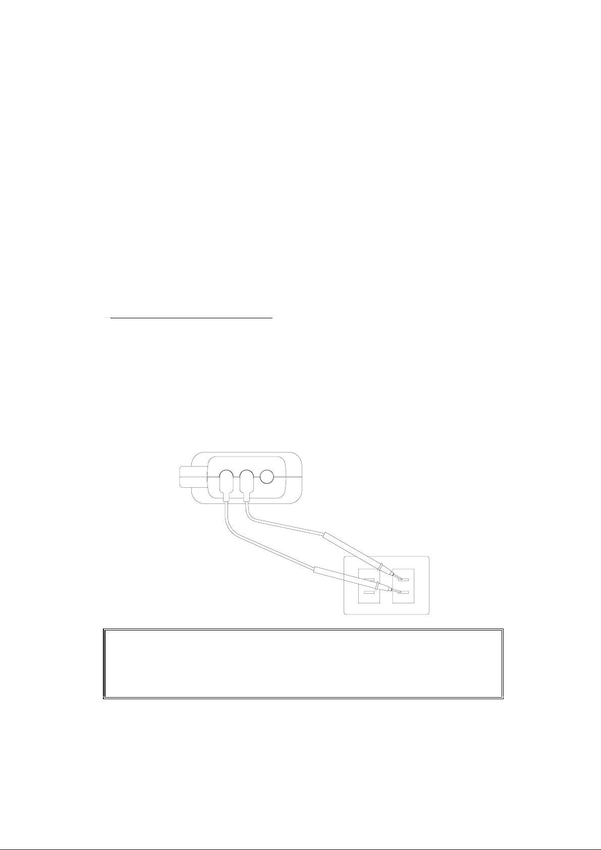
3.2.1.DC Voltage
a. Set the rotary switch to V DC.
b. Insert the test leads into the input terminals.
c. Connect the test probes of the test leads in PARALLEL to the circuit to be
10
Page 13

measured.
d. The clamp meter will automatically select the appropriate range. If manual
selection of the range is required, press the range button.
e. Read the measured value from the LCD display.
3.2.2.AC Voltage
a. Set the rotary switch to V AC
b. Insert the test leads into the input terminals.
c. Connect the test probes of the test leads in PARALLEL to the circuit to be
measured.
d. The clamp meter will automatically select proper range. If users want to
select range, press the range button.
e. Read the measured value from the LCD display.
WARNING
Before taking any in-circuit resistance measurement, remove power from the circuit
being tested and discharge all the capacitors.
3.3. Resistance Measurement
3.3.1. Set the rotary switch to Ω
3.3.2. Insert the test leads into the input terminals.
3.3.3. Connect the test probes of the test leads to the two ends of the resistor or
circuit to be measured.
3.3.4. The clamp meter will automatically select proper range If manual
selection of the range is required, press the range button.
.3.3.5. Read the measured value from the LCD display.
3.4. Continuity Measurement.
3.4.1. Set the rotary switch to Continuity
3.4.2. Insert the test leads into the input jack.
3.4.3. Connect the test prods of the test leads to the two ends of the resistor or
circuit to be measured.
3.4.4. Read the measured value from the LCD display.
3.4.5. If the resistance is lower than 40 Ω, the internal sounder will operate.
Diode Test
a. Set the rotary switch to diode test.
b. Insert the test leads to the input terminals
11
Page 14

c. Connect the test probes of the test leads to the two ends of a diode
d. Read the diode voltage from the LCD display
3.5 Frequency Measurement
a. Set the rotary switch to Hz
b. Insert the test leads to the input terminals
c. Connect the test probes of the test leads to the circuit to be measurement.
d. Adjust the voltage sensitivity by pressing RANGE button. The default sensitivity is
10mV. Pressing RANGE button will change the sensitivity to 100mV, or 1V. The
sensitivity will be displayed momentarily when RANGE button is pressed.
The higher the frequency, the highrer the sensitivity (such as 100mVor 1V) may be
needed. If the sensitivity is set at 10mV, a stable reading might not be o btainable on
the LCD display.
3.6. Relative Reading Measurements.
The REL button can be used to make a relative measurement. Once the button is
pushed, the current reading is set to zero and a zero symbol shall be displayed on
LCD. All the subsequent measurement shall be displayed as a relative value with
respect to the value being zeroed. Press the zero button for 2 seconds to return to
normal mode. But this function is disabled if MAX/MIN function is enab led. Please
watch for the symbol displayed on LCD.
3.7. Holding the LCD Reading
Press the HOLD button, then the reading shall be held and kept o n LCD.
3.8. Finding the MAX/MIN Value.
Press the MAX/MIN button to enable the maximum and minimum values to be
recorded and updated during measurement. Push the button once, the maximum
value shall be displayed and updated. Push again (second push), the minimum value
shall be displayed. Push again (third push), MAX/MIN function shall be disabled and
return to the normal measurement mode. If MAX/MIN button is pressed, the ZERO
function will be disabled and the ZERO symbol will disappear from LCD.
12
Page 15
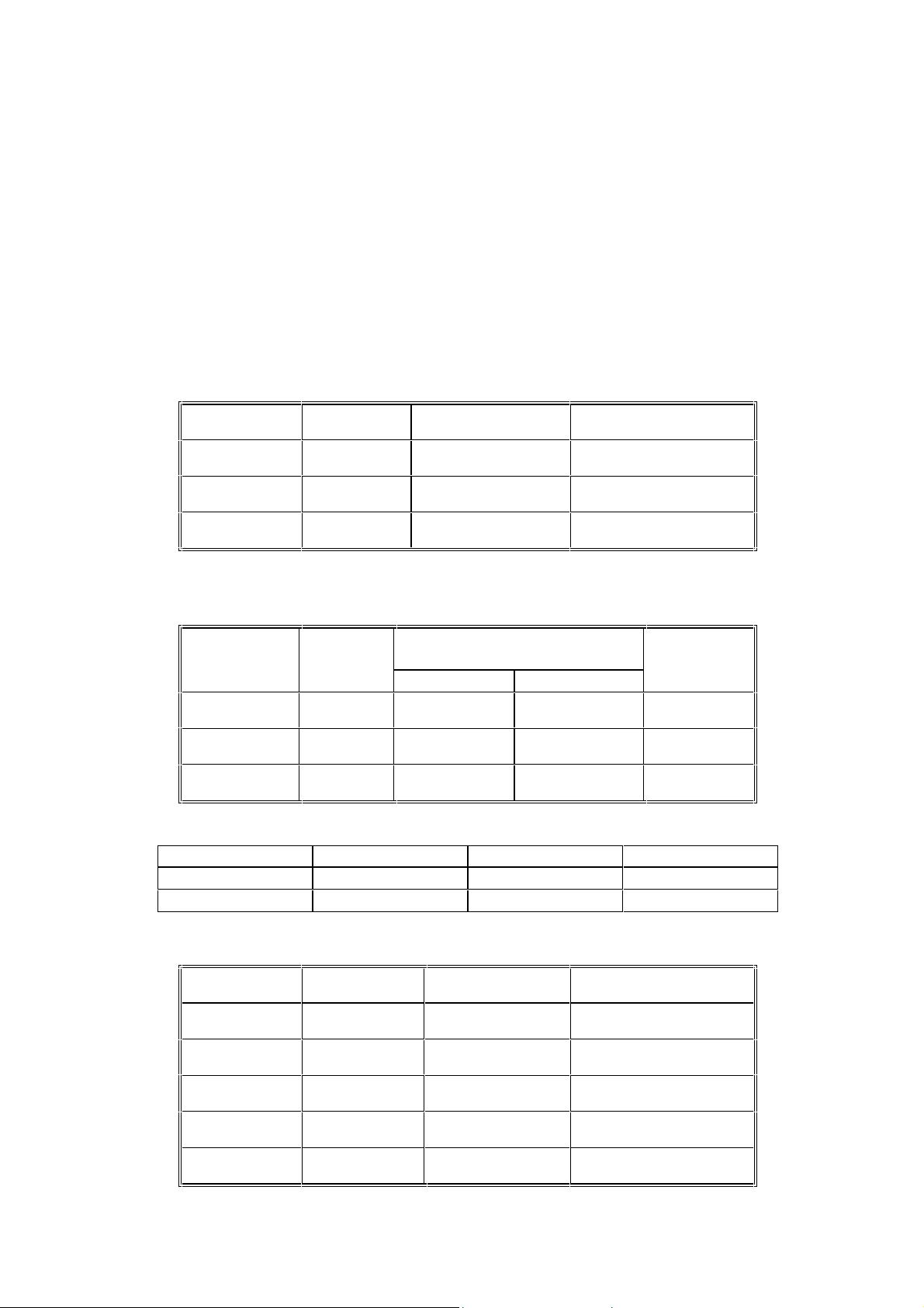
4. Specifications(@ 23°C 5°C)
DC Current:
Range Resolution Accuracy (of rdg) Overload Protection
400A 0.1A
0-2000A 1A
2000-2500A 1A
1.5%3dgts
1.5%3dgts
2.0%3dgts
DC 3000A
DC 3000A
DC 3000A
AC Current (True RMS Crest Factor < 4):
Range Resolution Accuracy (of rdg) Overload
Protection
50/60 Hz 40 - 1KHz
400A 0.1A
0-1000A 1A
1000-2100A 1A
1.5%5dgts 2.0%5dgts
2.0%5dgts 2.5%5dgts
2.5%5dgts 3.0%5dgts
AC 3000A
AC 3000A
AC 3000A
Current Analog Output
Range Output Accuracy Overload Protection
0 - 400A 1mV/A
400 - 2100A 1mV/A
2.5% 0.5A
2.5% 5A
600V AC
600V AC
DC Voltage:(Autorange & Manual, Overload Protection 800VAC for all range)
Range Resolution Accuracy(of rdg) Input Impedance
400mV 0.1mV
4V 0.001V
40V 0.01V
400V 0.1V
600V 1V
1.5%3dgts 10MΩ
1.5%3dgts 5MΩ
1.5%3dgts 5MΩ
1.5%3dgts 5MΩ
1.5%3dgts 5MΩ
13
Page 16

14
Page 17
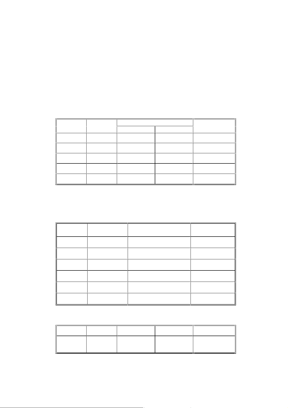
AC Voltage(True RMS , Crest Factor < 4)
(Autorange & Manual, Overload Protection 800VAC for all range)
Range Resolution Accuracy (of reading) Input Impedance
50/60 Hz 40 - 1KHz
400mV 0.1mV --------
1
---------
1
---------
1
4V 0.001
40V 0.01V
400V 0.1V
600V 1V
1
Though 400mVAC can be selected by RANGE key, it is not designed to measured
1.5%5dgts 2.0%5dgts 5MΩ
1.5%5dgts 2.0%5dgts 5MΩ
1.5%5dgts 2.0%5dgts 5MΩ
1.5%5dgts 2.0%5dgts 5MΩ
AC mV. So no accuracy is listed for AC 400mV range.
Resistance Ω (Autorange & Manual, Open Circuit Voltage ≤ 0.5V)
Range Resolution Accuracy
(of reading)
400Ω 0.1Ω 1.5%3dgts
4KΩ 1Ω 1.5%3dgts
40KΩ 10Ω 1.5%3dgts
400KΩ 100Ω 1.5%3dgts
4MΩ 1KΩ 1.5%3dgts
Overload
Protection
600VAC
600VAC
600VAC
600VAC
600VAC
40MΩ 10KΩ 1.5%3dgts
Resistance (Ω) and Continuity:(open voltage 0.4V)
Range Resolution Accuracy Beeping OL Protection
40-400Ω 0.1Ω 1.0%
rdg2dgts
15
< 40.0 Ω
(approx.)
600VAC
AC 600V
Page 18
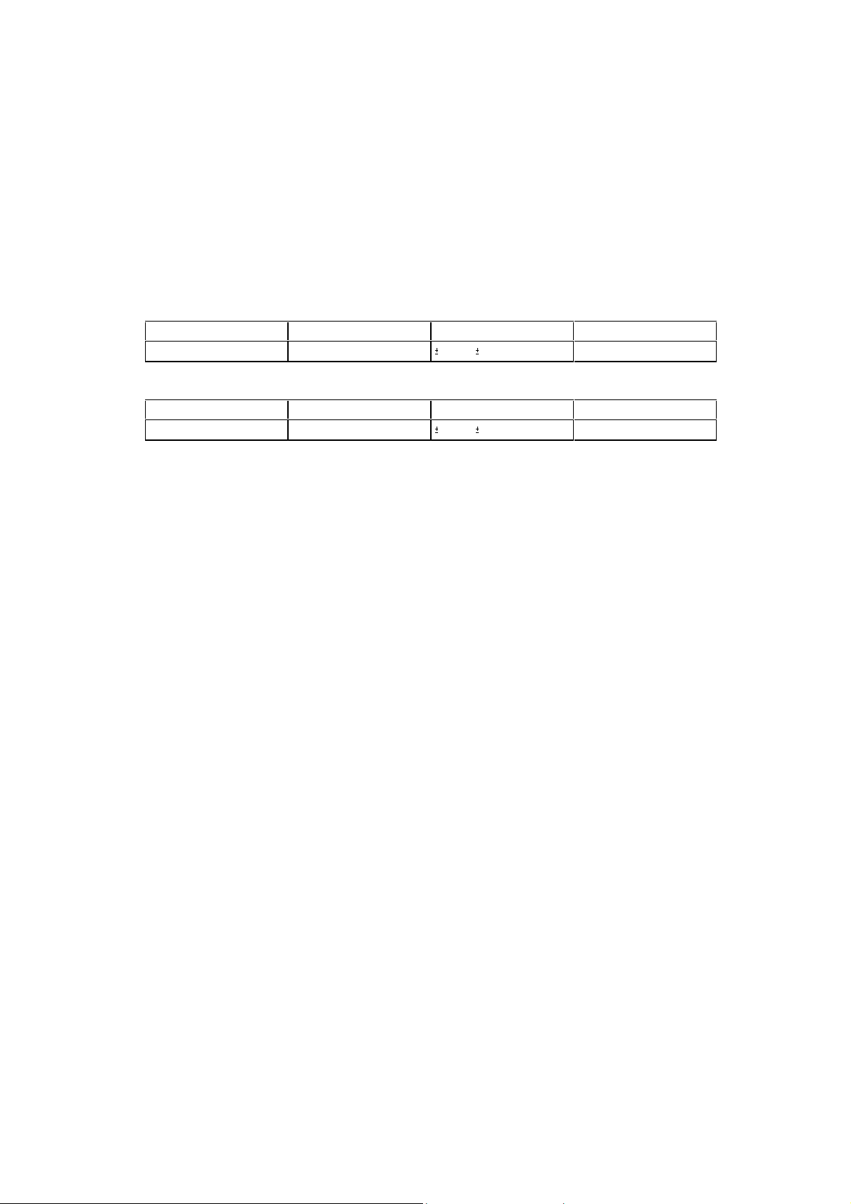
Diode Test
Range Resolution Accuracy Overload Protection
3V 0.001V
Frequency (Hz, Overload Protection 600VAC, Sensitivity selected by RANGE button)
Range Resolution Accuracy Sensitivity
100Hz – 1000KHz 0.01Hz - 100Hz
2.5% 5dgts
0.5% 2dgts
600VAC
10mV/100mV/1V
16
Page 19

Indoor Use
Conductor Size :Cable Φ55mm. (approx.)
Bus Bar 65mm( D) x 24mm(W)
Battery Type : 9V
Display : 3 3/4 LCD with 40 seg. bargraph
Range Selection : Auto and manual
Overload Indication : left most digit blinks
Power Consumption : 12 mA (approx.)
Low battery Indication :
B
Sampling Time : 2 times/sec. (display) 20 times/sec. (bargraph)
Operating Temperature : 4°C to 50°C
Operating Humidity : less than 85% relative
Altitude : up to 2000M
Storage Temperature : -20°C to 60°C
Storage Humidity : less than 75% relative
Dimension : 271mm (L) x 112mm (W) x 46mm (H)
10.7" (L) x 4.4" (W) x 1.8" (H)
Weight : 647 g/22.8 oz (batteries included)
Accessories : Carrying bag x 1
Users manual x 1
9V battery x 1
17
Page 20
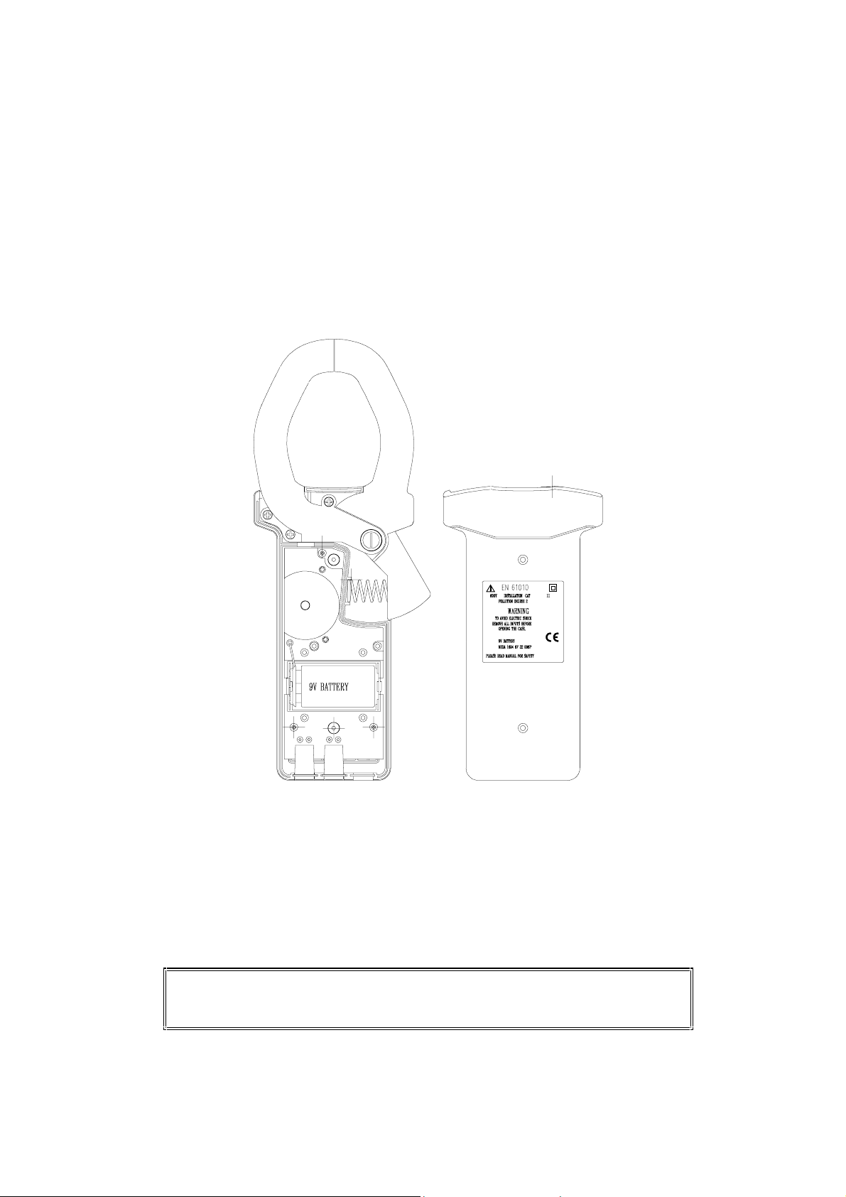
5.Battery Replacement
When the low battery symbol is displayed on the LCD, replace the old battery with a new
battery.
5.1.Turn the power off and remove the test leads from the clamp meter.
5.2.Remove the screws from the bottom half of the case.
5.3.Lift and remove the bottom half of the case.
5.4.Remove the old battery.
5.5.Insert new 9V battery.
5.6.Replace the bottom half of the case and secure the screws.
WARNING
Do not touch or adjust any parts inside the clamp meter when the bottom case is
open.
18
Page 21
6. Maintenance & Cleaning
Servicing not covered in this manual should only be performed b y qualified p erso nnel.
Repairs should only be performed by qualified personnel.
Periodically wipe the case with a damp cloth and detergent; do not use abrasives or
solvents.
19
 Loading...