

Page 1
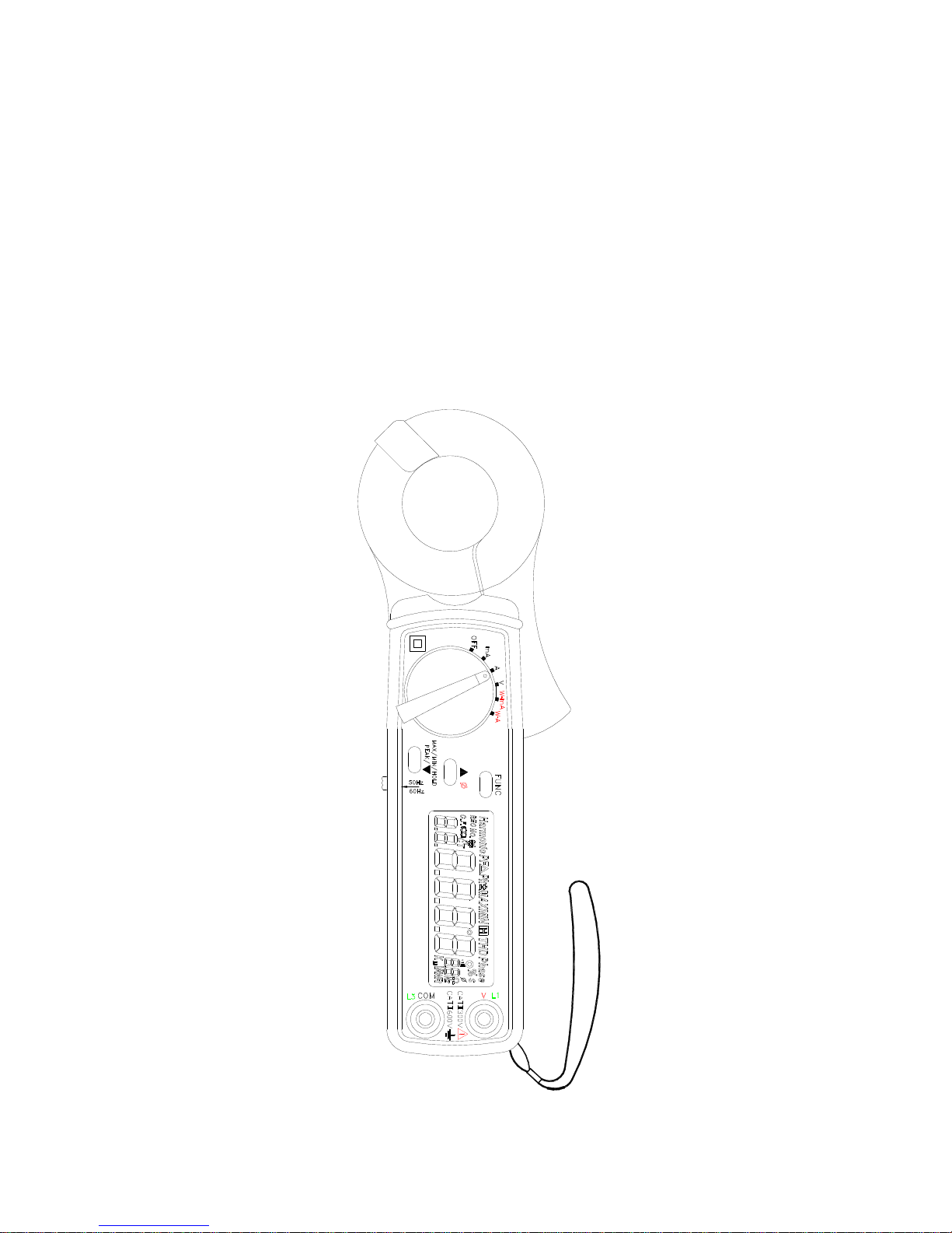
Power Harmonics and Leakage Tester
Model 21/23
Leakage and Harmonics Tester
Model 19
Users Manual
3
3
m
ERR
AUTO-POWER-OFF
Ture RMS
PROVA INSTRUMENTS INC.
Page 2
EN 61010-2-032
CAT II 600V
CAT III 300V
Pollution Degree 2
Definition of Symbols:
Caution: Refer to Accompanying Documents
Caution: Risk of Electric Shock
Double Insulation
Over-voltage Category I (CAT I):
Equipment for connection to circuits in which measures are
taken to limit the transient over-voltages to an appropriate low
level.
Over-voltage Category II (CAT II):
Energy-consuming equipment to be supplied from the fixed
installation.
Over-voltage Category III (CAT III):
Equipment in fixed installations.
WARNING: If the clamp meter is used in a manner
Not specified by the manufacturer, the protection
Provided by the clamp meter may be impaired.
Page 3

TABLE OF CONTENTS
I. FEATURES ................................................................................................................... 1
II. PANEL DESCRIPTION .............................................................................................. 2
III. OPERATING INSTRUCTIONS................................................................................. 5
III.1. Measurement of AC mA and A ........................................................................... 5
III.1.1. True RMS value of AC Current..................................................................................6
III.1.2. HOLD, MAX, MIN and PEAK of AC Current.........................................................7
III.1.3. Harmonics of AC Current in Magnitude (mA or A).................................................8
III.1.4. Harmonics of AC Current in Percentage (%)...........................................................8
III.1.5. Total Harmonic Distortion (% THD-F) ....................................................................9
III.1.6. Crest Factor (C.F.) ................................................................................................... 10
III.1.7 Frequency of AC Current ......................................................................................... 10
III.2 Measurement of AC Voltage.............................................................................. 11
III.2.1. True RMS value of AC Voltage................................................................................ 12
III.2.2. HOLD, MAX, MIN and PEAK value of AC Voltage............................................. 12
III.2.3. Harmonics of AC Voltage in Magnitude (V).......................................................... 13
III.2.4. Harmonics of AC Voltage in Percentage (%) ........................................................ 13
III.2.5. Total Harmonic Distortion (% THD-F) ................................................................. 14
III.2.6. Crest Factor (C.F.) ................................................................................................... 15
III.2.7 Frequency of AC voltage.......................................................................................... 15
III.3 Measurement of Single Phase AC Power Quality (21, 23) ............................. 16
III.3.1 Single Phase AC Watt ............................................................................................... 17
III.3.2. Apparent Power (VA, KVA) and Reactive Power (VAR, KVAR).......................... 17
III.3.3. Power Factor (PF), and Phase Angle (Φ)............................................................. 18
III.3.4. Horse Power (H.P.).................................................................................................. 19
III.3.5. Energy (mWH, WH, or KWH)................................................................................ 19
III.4 Measurement of the Balanced 3 Phase AC Power Quality (21, 23).............. 20
III.5 Measurement of the Balanced 3 Phase Sequence (21, 23)........................... 21
IV. SET THE CT RATIO ................................................................................................ 22
V. DISABLE AUTO-POWER-OFF ..............................................................................22
VI. SPECIFICATIONS (23°C±5°C) .............................................................................. 23
VII. BATTERY REPLACEMENT ................................................................................. 31
VIII. MAINTENANCE & CLEANING........................................................................... 32
Page 4

1
I. FEATURES
a. Active (W, KW, HP), reactive (VAR, KVAR) and apparent (VA, KVA) power.
b. Power factor (PF), phase angle (Φ), and energy (mWH, WH, KWH).
c. Measurement of standby power consumption for IT products.
d. Non-interrupted AC current harmonic analysis.
e. 1 to 99
th
order of harmonics at 1.0% basic accuracy.
f. Total harmonic distortion (%THD-F) and crest factor (CF).
g. True RMS measurement of V and A at 0.5% basic accuracy.
h. Fast peak function (39μs for 50 Hz, 33μs for 60Hz).
i. Measurement of balanced 3Φ power.
j. Measurement of balanced 3Φ sequence.
k. Programmable CT ratio from 1 to 250.
l. Max, Min and data hold functions.
m. Leakage current measurement at 10μA resolution.
n. Active power in H.P.
o. Auto power off function in 30 minutes.
p. Shielded Jaw immune to external interference (Model 19, 21)
Page 5
2
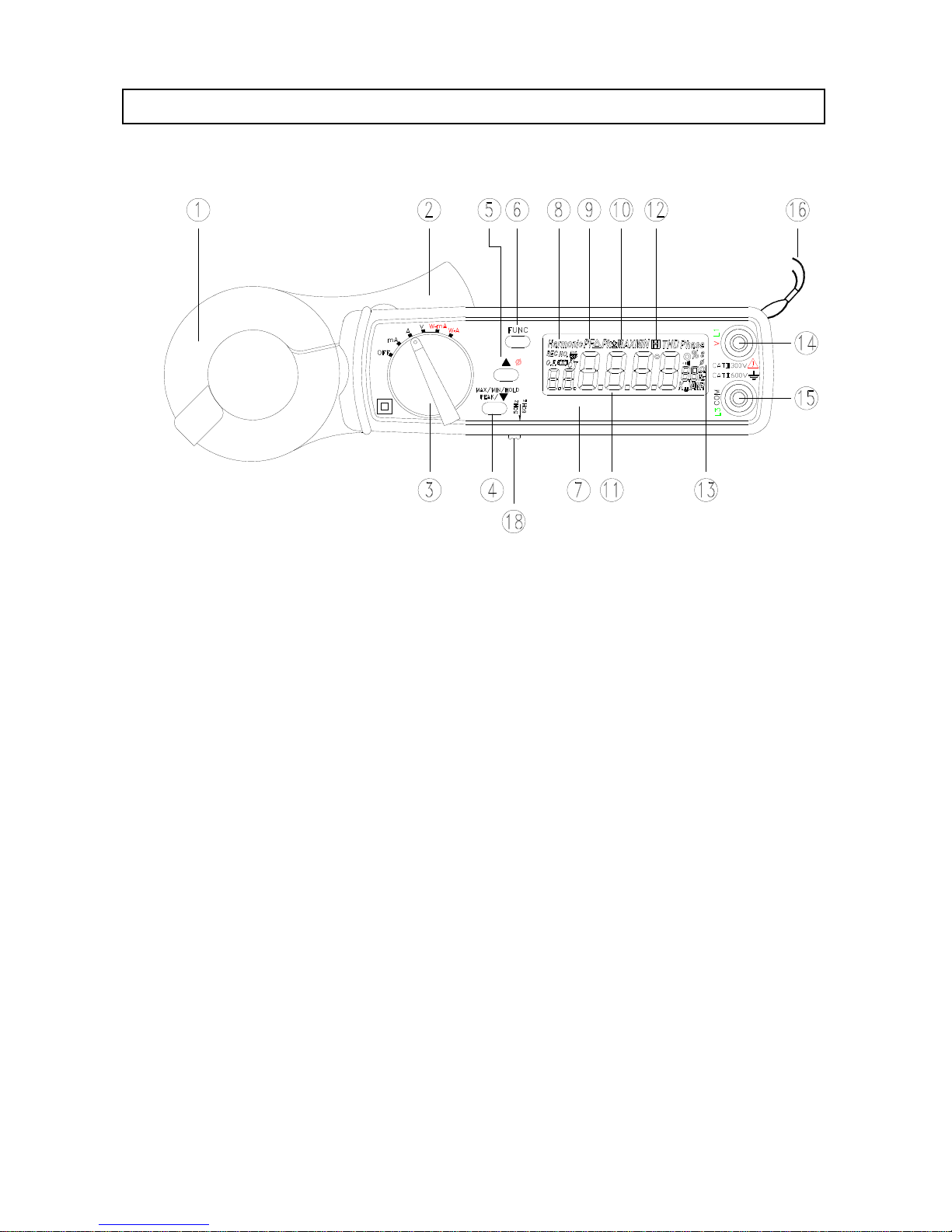
II. PANEL DESCRIPTION
3
3
m
ERR
AUTO-POWER-OFF
Ture RMS
1. Transformer Jaw Assembly
This is used to pick up current signal. To measure AC current or Power/Watt, the jaw
must enclose conductor completely.
2. Transformer Trigger
Press the trigger to open the jaw.
3. Rotary Switch
This is used to turn the power on and select measurement of current, voltage or
power.
4. MAX/MIN/HOLD/PEAK and ▼ Button
In the measurement of mA, A, or V, press this button to perform function of
MAXIMUM, MINIMUM, HOLD and PEAK. It is also used to decrement the order of
harmonics or CT ratio.
If this button is hold when turning on power, the tester can perform measurement of
phase sequence instead of phase angle in the balanced 3Φ power system.
Page 6

3
5. ▲ 3Φ Button
This button is used to increment order of harmonics or CT ratio. When the rotary
switch is set at W-mA or W-A position, press this button to select measurement of
balanced 3Φ power instead of single-phase power.
This button is also used to select AUTO Hz. If users hold this button and turn the
power on, the unit will automatically detect the frequency of the signal within 40 to 65
Hz. If the frequency is outside 40 to 65 Hz, the unit will select 50 or 60 Hz based
upon the position of sliding switch 18.
6. FUNC Button
In the measurement of mA, A, or V, press this button to select function of harmonics,
THD-F, or CF. In the measurement of W-mA or W-A, press this button to select
function of VA, VAR, PF, phase angle, HP, or energy (KWH).
7. LCD
This is a 4+2+2 digit Liquid Crystal Display. Function symbols, units, sign, decimal
points, low battery symbols, max, min symbols, peak and harmonic symbols are
included.
8, 9, 10, 12
Those are symbols of selected functions such as, Harmonic, PEAK, MAX, MIN or
HOLD.
11. Primary Digits
These digits display the value of measurement, such as current, voltage, or power.
13. Symbols of Units
These are symbols of current, voltage, and power. There are two digits used to
display the fundamental frequency 50 or 60 Hz.
14. V Input Terminal
This terminal is used as input for voltage and power measurements.
15. COM Terminal
This terminal is used as common reference input.
16. Hand Strap
Put your hand through the hole of hand strap to avoid accidental drop of the clamp
meter.
Page 7

4
18. Sliding Switch
Users should select the correct fundamental frequency (50/60 Hz) by moving the
sliding switch to a correct position.
Page 8
5
III. OPERATING INSTRUCTIONS
III.1. Measurement of AC mA and A
NOTE:
1. Select the correct fundamental frequency (50 or 60 Hz) of current by moving the
sliding switch at the side of the tester. Or hold the
▲
button to select AUTO Hz.
2. Select the proper position of the rotary switch for the range of current. If the AC
current is less than 0.6A, then set the rotary switch at the position of mA. If the
AC current is greater than 0.6A, then set the rotary switch at the position of A.
3. If the peak value of the input AC current is greater than the maximum value of
the range, then symbol of OL will be displayed.
4. If users hold the
▲
button and turn the power on, the unit enters the AUTO Hz
mode. The unit will automatically detect the frequency between 45 to 65Hz.
Additional error occurs if the measured frequency is not 50 or 60 Hz.
NOTE: Whenever the rotary switch is set at a new position, the CT ratio and
fundamental frequency will be displayed first.
WARNING: If the unit clamps on to a load (current) about twice the range, the unit
not only display OL, but also display Low Battery.
NOTE: If the CT ratio is not 1, a symbol of “CT” will be shown in the LCD display
for the measurement of mA or A. The reading of current shown in LCD is equal to
the true RMS value measured by the tester multiplied by CT ratio (A
LCD
= A
RMS
×
CT).
Page 9
6
+
T
u
r
e
R
M
S
A
U
T
O
-
P
O
W
E
R
-
O
F
F
E
R
R
m
3
3
WARNING: Make sure that all the test leads are disconnected from the meter's
terminals for current measurement.
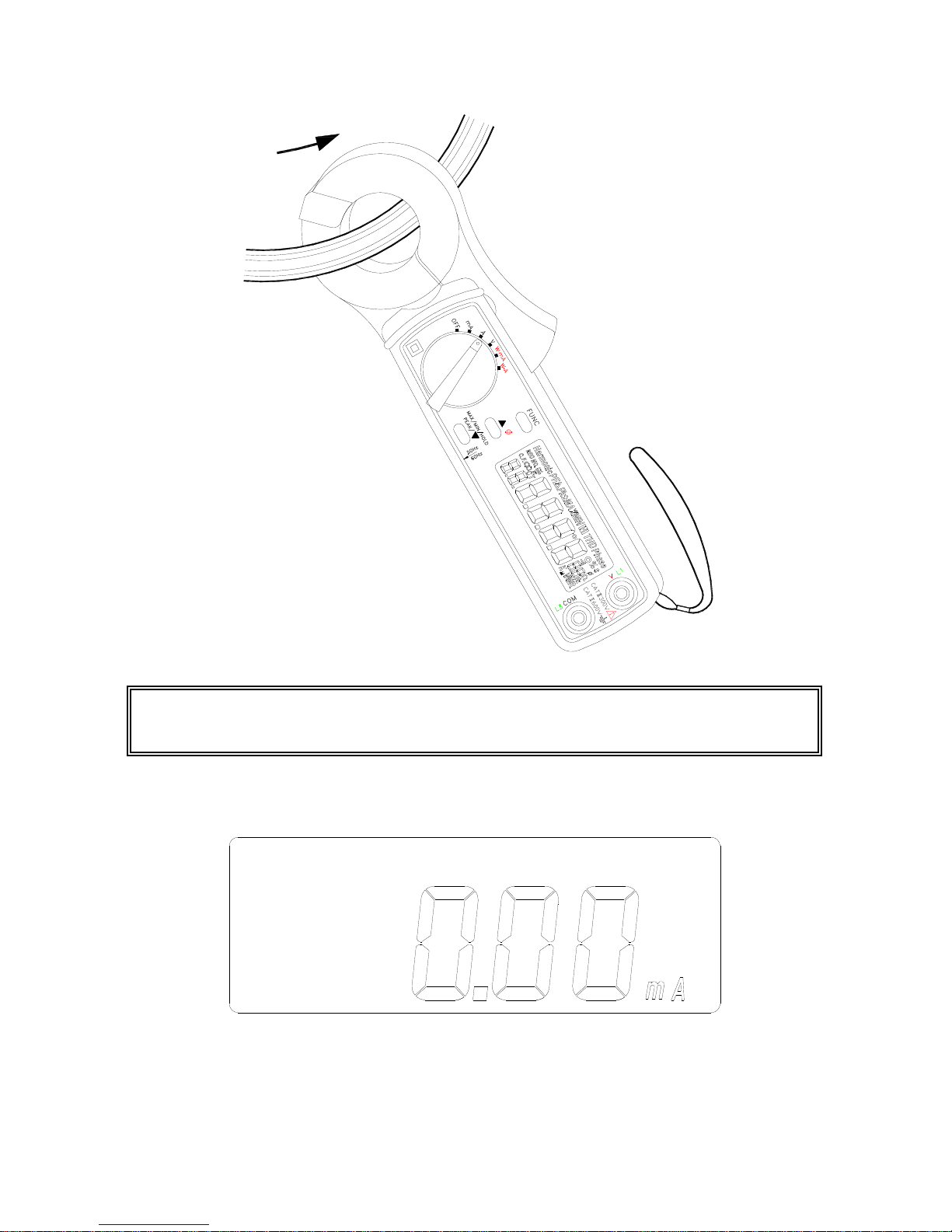
III.1.1. True RMS value of AC Current
Page 10
7
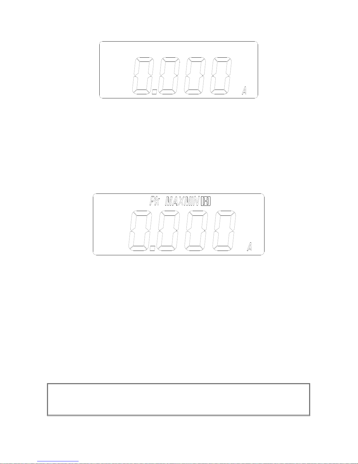
a. Set the rotary switch at mA or A depending on the range of AC current.
Then select the correct frequency by moving the sliding switch at the side
of the tester.
b. Press the trigger to open the jaw and fully enclose the conductor to be
measured.
c. Read the measured value from the LCD display.
III.1.2. HOLD, MAX, MIN and PEAK of AC Current.
a. Set the rotary switch at mA or A depending on the range of AC current.
Then select the correct frequency by moving the sliding switch at the side
of the tester.
b. Press the trigger to open the jaw and fully enclose the conductor to be
measured.
c. The measured value from the LCD display. If the ▼ button is pressed,
the symbol of “HOLD”, “MAX”, “MIN” or “PEAK” will be shown in LCD
alternatively. And the value of the HOLD, MAX, MIN or PEAK function will
be displayed in LCD alternatively.
d. To return to the display of current measurement, hold the ▼ button for
more than 2 seconds.
NOTE: The PEAK function displays the maximum value of a AC periodic
waveform. The sampling time for the PEAK function is 39 μs (50Hz) or 33μs
(60Hz). The HOLD, MAX, or MIN function displays the true RMS value.
Page 11
8
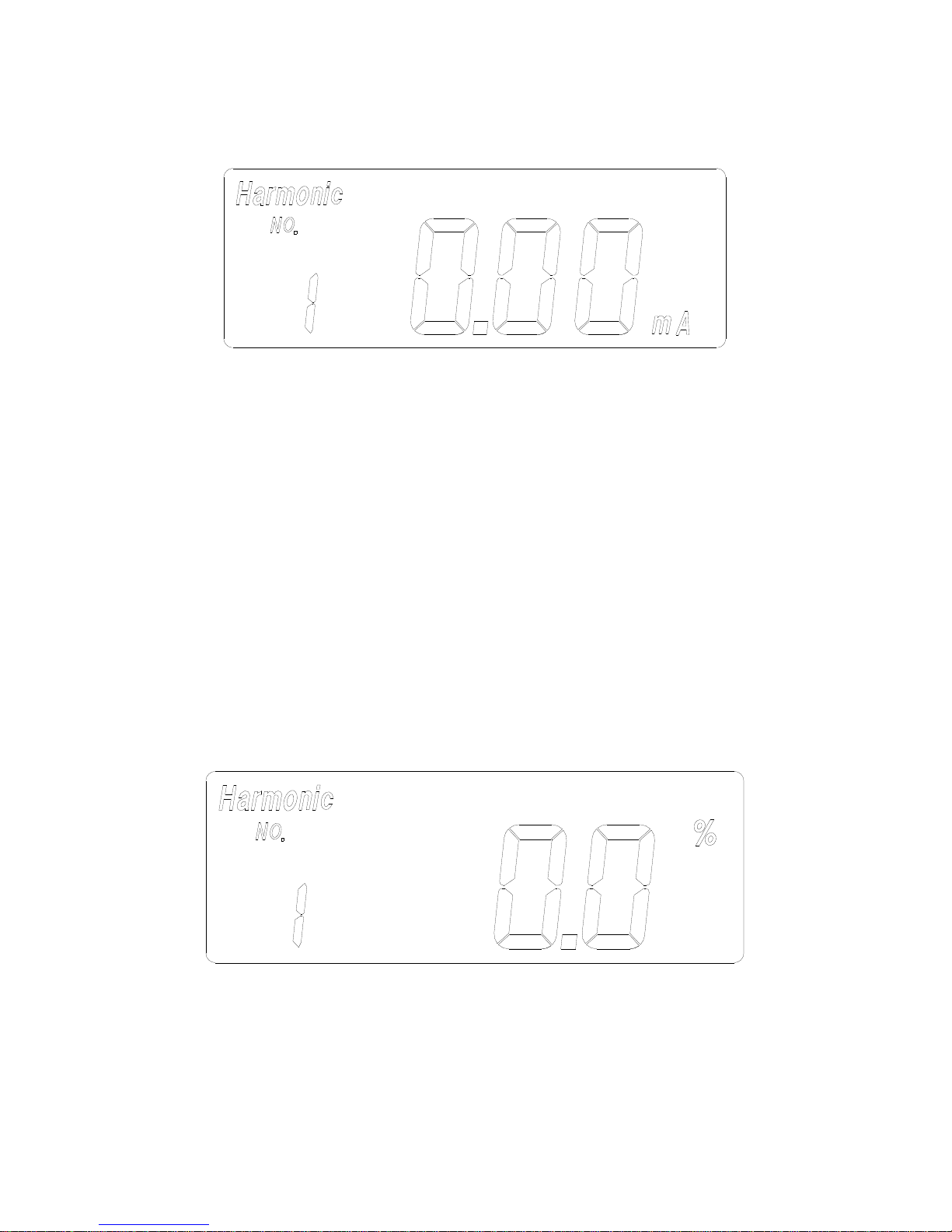
III.1.3. Harmonics of AC Current in Magnitude (mA or A)
a. Set the rotary switch at the position of “mA” or “A” depending on the range
of AC current. Then select the correct fundamental frequency by moving
the sliding switch at the side of the tester.
b. Press the trigger to open the jaw and fully enclose the conductor to be
measured.
c. Press the FUNC button once. The symbols of “Harmonic” and “NO” will
be shown in LCD. The n-th order (1 to 99) will be shown in front of the
reading of the magnitude (mA or A) of the current.
d. Press the ▲ or ▼ button to increment or decrement the order of
harmonics in front of the reading. The number will roll over when the
maximum (99) or minimum (1) is reached.
III.1.4. Harmonics of AC Current in Percentage (%)
a. Set the rotary switch at the position of “mA” or “A” depending on the range
of AC current. Then select the correct fundamental frequency by moving
the sliding switch at the side of the tester.
b. Press the trigger to open the jaw and fully enclose the conductor to be
Page 12
9
measured.
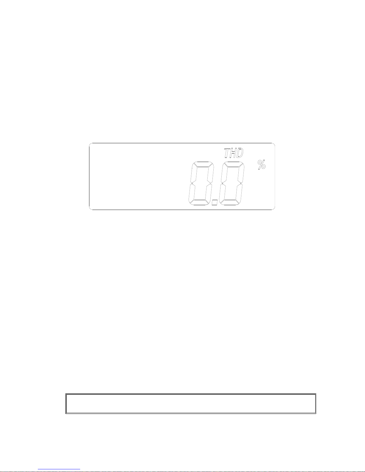
c. Press the FUNC button twice. The symbols of “Harmonic” and “NO” will
be shown in LCD. The n-th order (1 to 99) will be shown in front of the
reading of the percentage (%) of the current.
d. Press the ▲ or ▼ button to increment or decrement the order of
harmonics in front of the reading. The number will roll over when the
maximum (99) or minimum (1) is reached.
III.1.5. Total Harmonic Distortion (% THD-F)
a. Set the rotary switch at the position of “mA” or “A” depending on the range
of AC current. Then select the correct fundamental frequency by moving
the sliding switch at the side of the tester.
b. Press the trigger to open the jaw and fully enclose the conductor to be
measured.
c. Press the FUNC button three times. The symbols of “THD” and “%” will be
shown in LCD. The total harmonic distortion in percentage with respect to
the fundamental frequency (50 or 60 Hz) will be measured and displayed.
%THD-F = (√(V2
2
+ V32 + … V492+ V502) / V1) * 100
Where,
V1: magnitude at the fundamental frequency
V2: magnitude at the second harmonics
…
V50: magnitude at the 50-th harmonics.
NOTE: In the measurement of THD, the response to the button or switch
operation becomes slow due to heavy math calculation.
Page 13
10
III.1.6. Crest Factor (C.F.)
a. Set the rotary switch at the position of “mA” or “A” depending on the range
of AC current. Then select the right frequency by moving the sliding switch
at the side of the tester.
b. Press the trigger to open the jaw and fully enclose the conductor to be
measured.
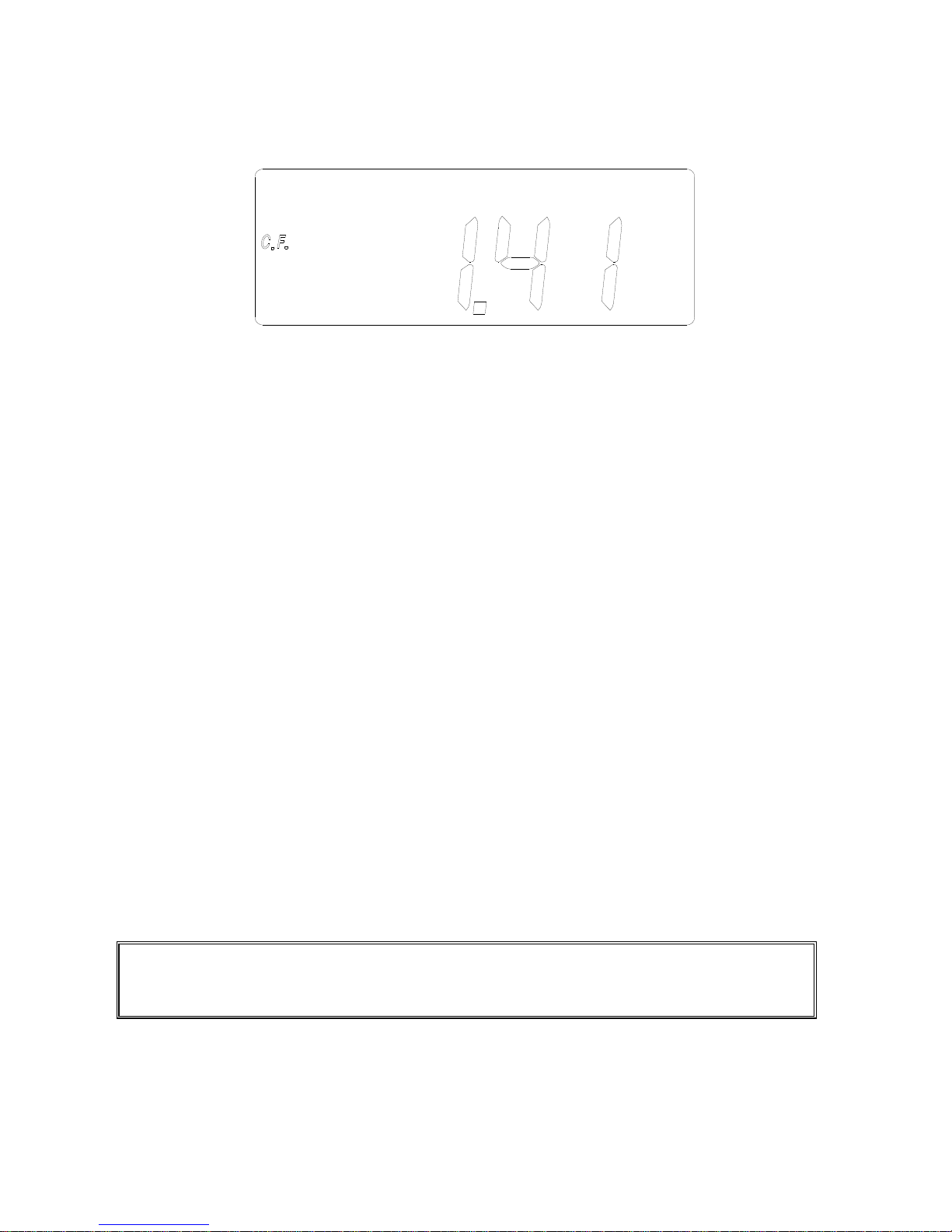
c. Press the FUNC button four times. The symbol of C.F. will be shown in
LCD. The crest factor (C.F.) will be measured and displayed. The crest
factor (CF) is defined as following:
C.F. = (peak value) / (RMS value)
III.1.7 Frequency of AC Current
a. Set the rotary switch at the position of “mA” or “A” depending on the range
of AC current.
b. Press the trigger to open the jaw and fully enclose the conductor to be
measured.
c. Press the FUNC button five times. The symbol of Hz will be shown in
LCD.
d. The frequency of AC current will be measured and shown in LCD. If the
frequency is less than 40 Hz, 0 Hz will be shown in LCD. If the frequency
is greater than 65 Hz, OL Hz will be shown in LCD.
NOTE: In the mA range, the AC current must be greater than 10mA for frequency
measurement. In the A range, the AC current must be greater than 1A for
frequency measurement.
Page 14
11
III.2 Measurement of AC Voltage
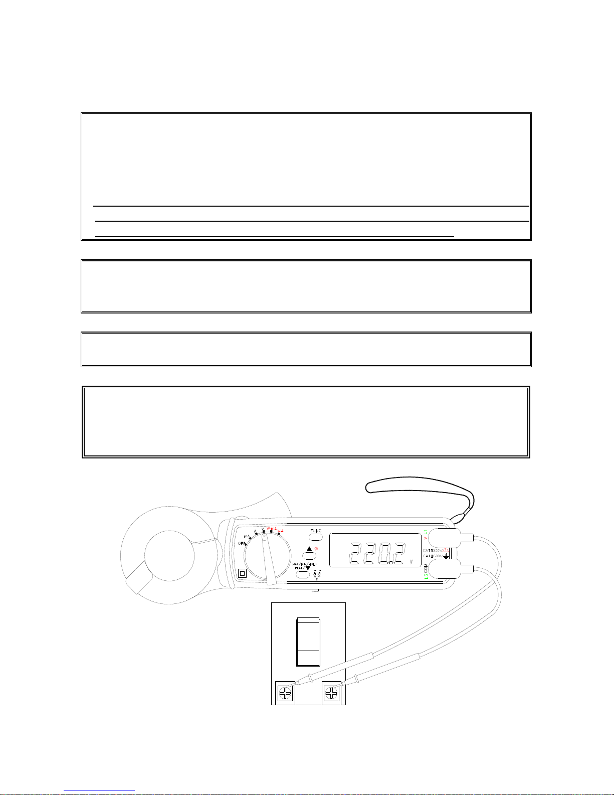
NOTE:
1. Select the correct fundamental frequency of voltage by moving the sliding switch
at the side of the tester.
2. If the peak value of the input AC voltage is greater than the maximum value of the
range, then symbol of OL will be displayed.
3. If users hold the
▲
button and turn the power on, the unit enters the AUTO Hz
mode. The unit will automatically detect the frequency between 45 to 65Hz.
Additional error occurs if the measured frequency is not 50 or 60 Hz.
NOTE: Whenever the rotary switch is set at a new position, the CT ratio and
fundamental frequency will be displayed first.
NOTE: If the CT ratio is not 1, a symbol of “CT” will be shown in the LCD display.
WARNING: Maximum input for ACV is 600. Do not attempt to take any
voltage measurement that exceeds the limits. Exceeding the limits could cause
electrical shock and damage to the clamp meter.
3
Ture RMS
AUTO-POWER-OFF
Page 15
12
III.2.1. True RMS value of AC Voltage
a. Set the rotary switch at position V. Then select the correct fundamental
frequency by moving the sliding switch at the side of the tester.
b. Insert the test leads into the input jack. Connect the test prods of the test
leads in PARALLEL to the circuit to be measured.
c. Read the measured RMS value from the LCD display.
III.2.2. HOLD, MAX, MIN and PEAK value of AC Voltage
a. Set the rotary switch at position V. Then select the correct fundamental
frequency by moving the sliding switch at the side of the tester.
b. Insert the test leads into the input jack. Connect the test prods of the test
leads in PARALLEL to the circuit to be measured.
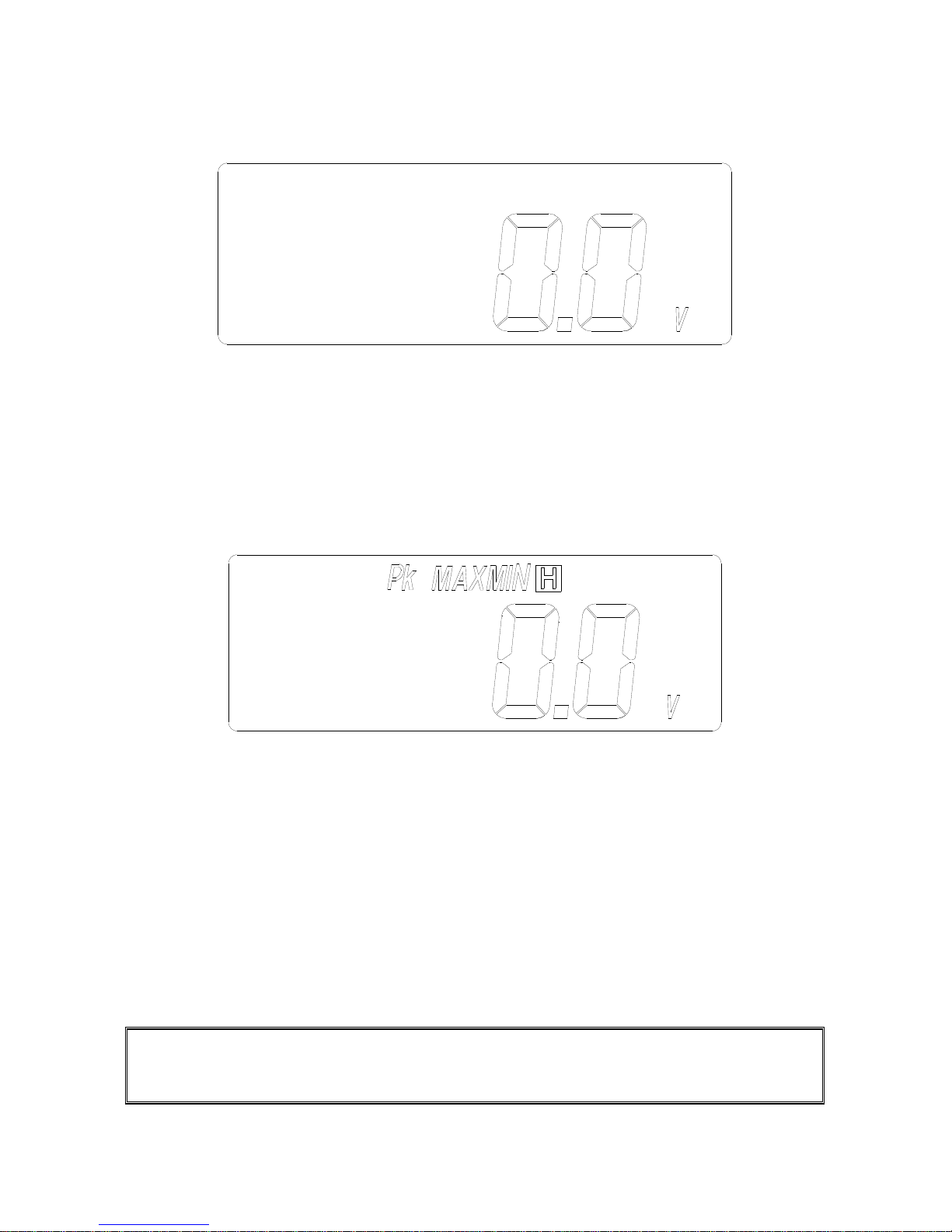
c. The measured value is displayed in the LCD display. If the ▼ button is
pressed, the symbol of “HOLD”, “MAX”, “MIN” or “PEAK” will be shown in
LCD alternatively. And the value of the HOLD, MAX, MIN or PEAK
function will be displayed in LCD alternatively.
d. To return to the display of current measurement, hold the ▼ button for
more than 2 seconds.
NOTE: NOTE: The PEAK function displays the maximum value of a AC periodic
waveform. The sampling time for the PEAK function is 39 μs (50Hz) or 33μs (60Hz).
The HOLD, MAX, or MIN function displays the true RMS value.
Page 16
13
III.2.3. Harmonics of AC Voltage in Magnitude (V)
a. Set the rotary switch at position V. Then select the correct fundamental
frequency by moving the sliding switch at the side of the tester.
b. Insert the test leads into the input jack. Connect the test prods of the test
leads in PARALLEL to the circuit to be measured.
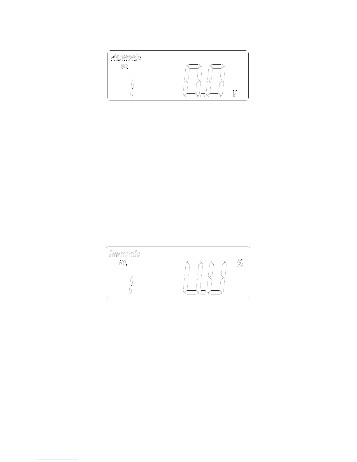
c. Press the FUNC button once. The symbols of “Harmonic” and “NO” will
be shown in LCD. The n-th order (1 to 99) will be shown in front of the
reading of the reading of the magnitude (V) of the voltage.
d. Press the ▲ or ▼ button to increment or decrement the order of
harmonics in front of the reading. The number will roll over when the
maximum (99) or minimum (1) is reached.
III.2.4. Harmonics of AC Voltage in Percentage (%)
a. Set the rotary switch at position V. Then select the correct fundamental
frequency by moving the sliding switch at the side of the tester.
b. Insert the test leads into the input jack. Connect the test prods of the test
leads in PARALLEL to the circuit to be measured.
c. Press the FUNC button twice. The symbols of “Harmonic” and “NO” will
be shown in LCD. The n-th order (1 to 99) will be shown in front of the
reading of the percentage (%) of the voltage.
d. Press the ▲ or ▼ button to increment or decrement the order of
harmonics in front of the reading. The number will roll over when the
maximum (99) or minimum (1) is reached.
Page 17
14
III.2.5. Total Harmonic Distortion (% THD-F)
a. Set the rotary switch at position V. Then select the correct fundamental
frequency by moving the sliding switch at the side of the tester.
b. Insert the test leads into the input jack. Connect the test prods of the test
leads in PARALLEL to the circuit to be measured.
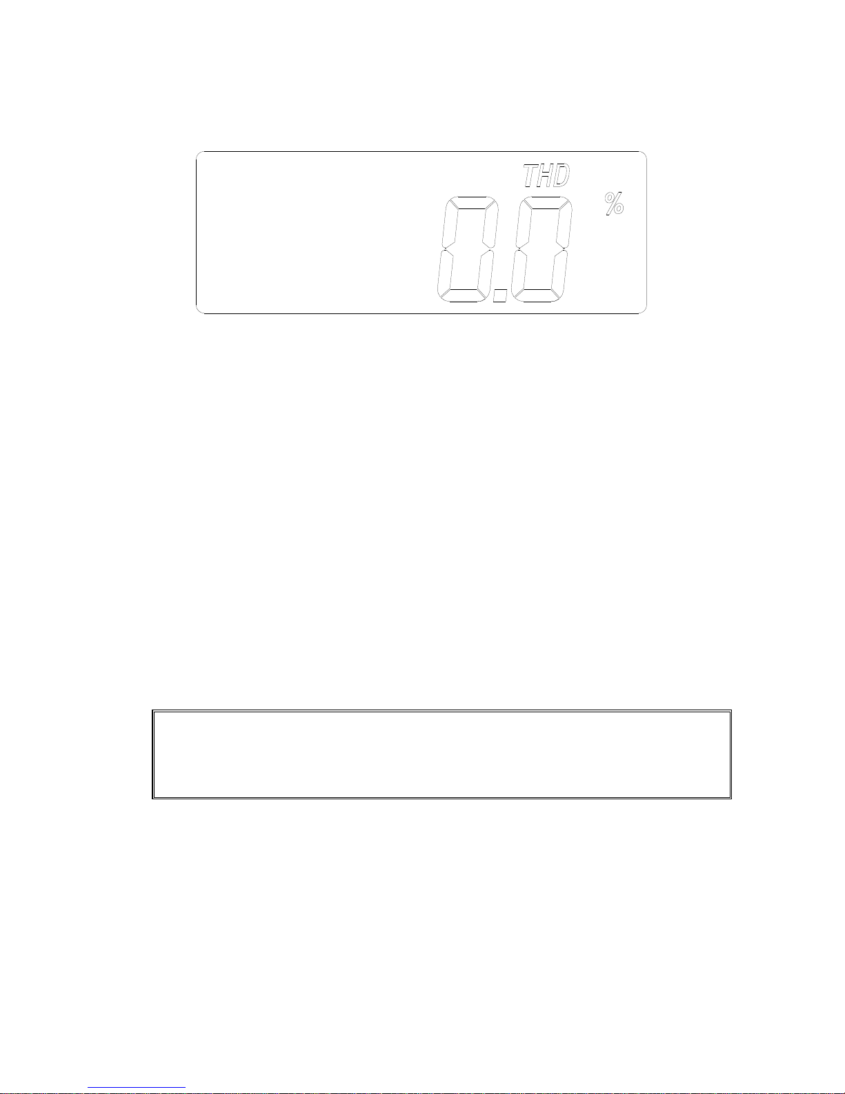
c. Press the FUNC button three times. The symbols of “THD” and “%” will be
shown in LCD. The total harmonic distortion in percentage with respect to
the fundamental frequency (50 or 60 Hz) will be measured and displayed.
%THD-F = (√(V2
2
+ V32 + … +V492+ V502) / V1) * 100
Where,
V1: magnitude at the fundamental frequency
V2: magnitude at the second harmonics
…
V50: magnitude at the 50-th harmonics.
NOTE: In the measurement of THD, the response to the button or switch
operation becomes slow due to heavy math calculation.
NOTE: For model 23, users can not disable the auto-power-off function
by holding the FUNC button for 2 seconds in the measurement of THD.
Page 18
15
III.2.6. Crest Factor (C.F.)
a. Set the rotary switch at position V. Then select the correct fundamental
frequency by moving the sliding switch at the side of the tester.
b. Insert the test leads into the input jack. Connect the test prods of the test
leads in PARALLEL with the circuit to be measured.
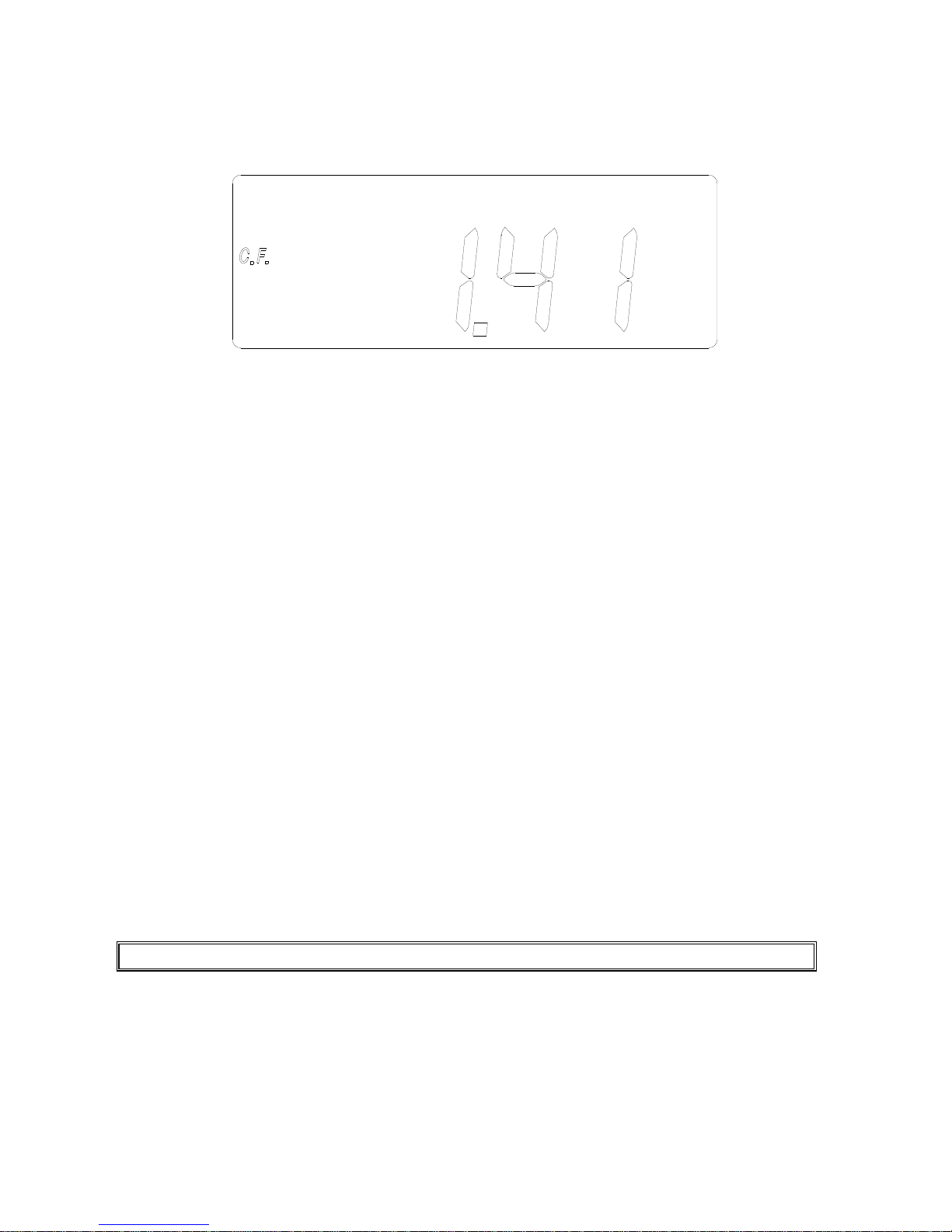
c. Press the FUNC button four times. The symbol of C.F. will be shown in
LCD. The crest factor (C.F.) will be measured and displayed. The crest
factor (CF) is defined as following:
C.F. (Crest Factor) = (Peak Value) / (RMS Value)
III.2.7 Frequency of AC voltage
a. Set the rotary switch at position V.
b. Insert the test leads into the input jack. Connect the test prods of the test
leads in PARALLEL with the circuit to be measured.
c. Press the FUNC button five times. The symbol of Hz will be shown in
LCD.
d. The frequency of AC voltage will be measured and shown in LCD. If the
frequency is less than 40 Hz, 0 Hz will be shown in LCD. If the frequency
is greater than 65 Hz, OL Hz will be shown in LCD
NOTE: The AC voltage must be greater than 50V for frequency measurement.
Page 19
16
III.3 Measurement of Single Phase AC Power Quality (21, 23)
NOTE:
1. Select the correct fundamental frequency of current and voltage by moving the
sliding switch at the side of the tester.
2. Select the proper position of the rotary switch for the range of current. If the AC
current is less than 0.6A, then set the rotary switch at the position of W-mA. I
f
the AC current is greater than 0.6A, then set the rotary switch at the position o
f
W-A.
3. If the peak value of the input AC current is greater than the maximum value o
f
the range, then symbol of OL will be displayed.
4. If users hold the
▲
button and turn the power on, the unit enters the AUTO Hz
mode. The unit will automatically detect the frequency between 45 to 65Hz.
Additional error occurs if the measured frequency is not 50 or 60 Hz.
NOTE: Whenever the rotary switch is set at a new position, the CT ratio and
fundamental frequency will be displayed first.
NOTE: If the CT ratio is not 1, a symbol of “CT” will be shown in the LCD display for
the measurement of W-mA or W-A.
A
U
T
O
-
P
O
W
E
R
-
O
F
F
T
u
r
e
R
M
S
--
+
+
--
+
3
Page 20
17
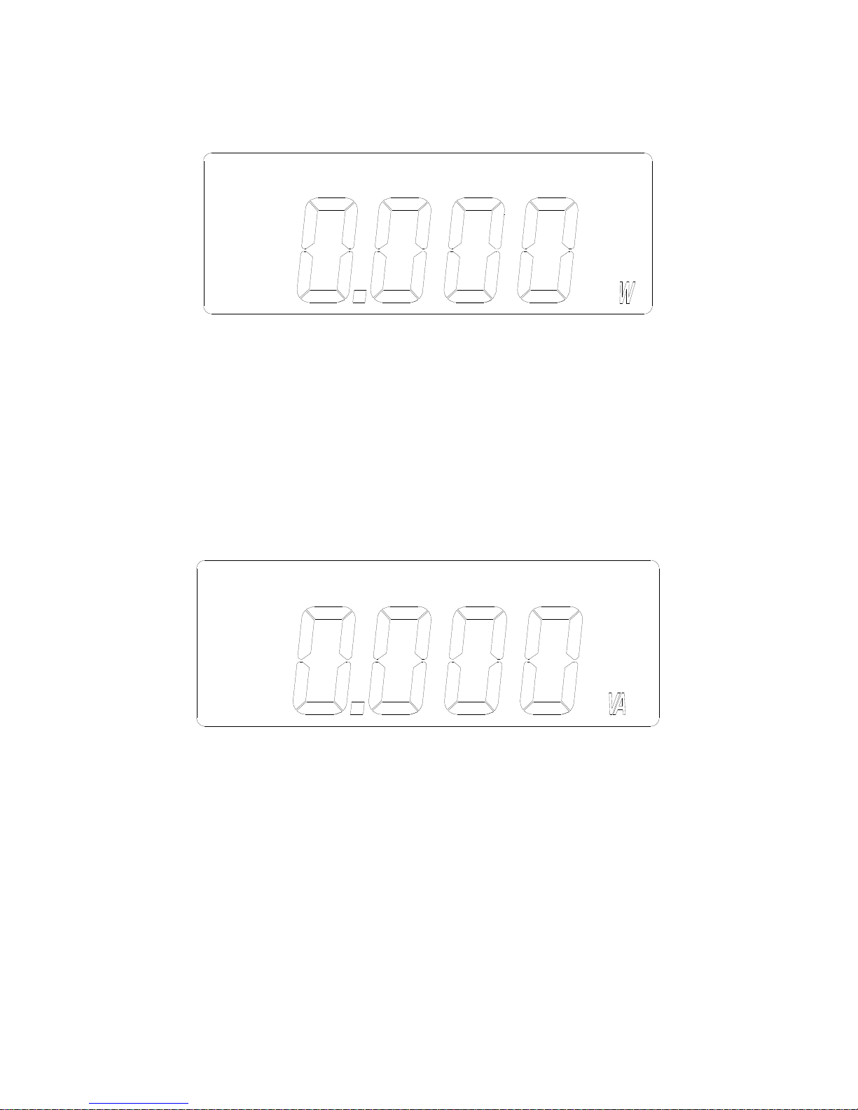
III.3.1 Single Phase AC Watt
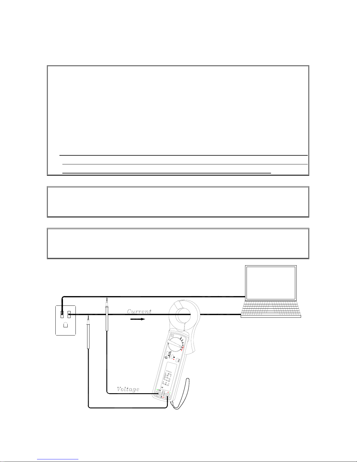
a. Connect the test leads to the voltage source in parallel with the load.
b. Clamp on one of the wire to the load. The current should flow from the front of
the tester to the side of the battery cover.
c. Select proper Watt range (W-mA or W-A).
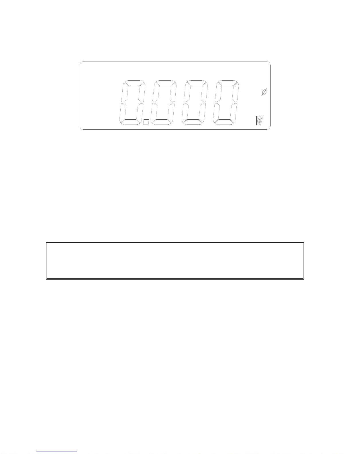
d. Read the value shown on LCD in mW, W, or KW. The unit of watt is
automatically scaled.
III.3.2. Apparent Power (VA, KVA) and Reactive Power (VAR, KVAR)
a. Connect the test leads to the voltage source in parallel with the load.
b. Clamp on one of the wire to the load. The current should flow from the front of
the tester to the side of the battery cover.
c. Select proper Watt range (W-mA or W-A).
d. The value of mW, W, or KW will be displayed in LCD. The unit of watt is
automatically scaled.
e. Press the FUNC button once to display VA or KVA. The unit is automatically
scaled.
f. Press the FUNC button twice to display VAR or KVAR. The unit is
automatically scaled.
Page 21
18
III.3.3. Power Factor (PF), and Phase Angle (Φ)
a. Connect the test leads to the voltage source in parallel with the load.
b. Clamp on one of the wire to the load. The current should flow from the front of
the tester to the side of the battery cover.
c. Select proper Watt range (W-mA or W-A).
d. The value of mW, W, or KW will be displayed in LCD. The unit of watt is
automatically scaled.
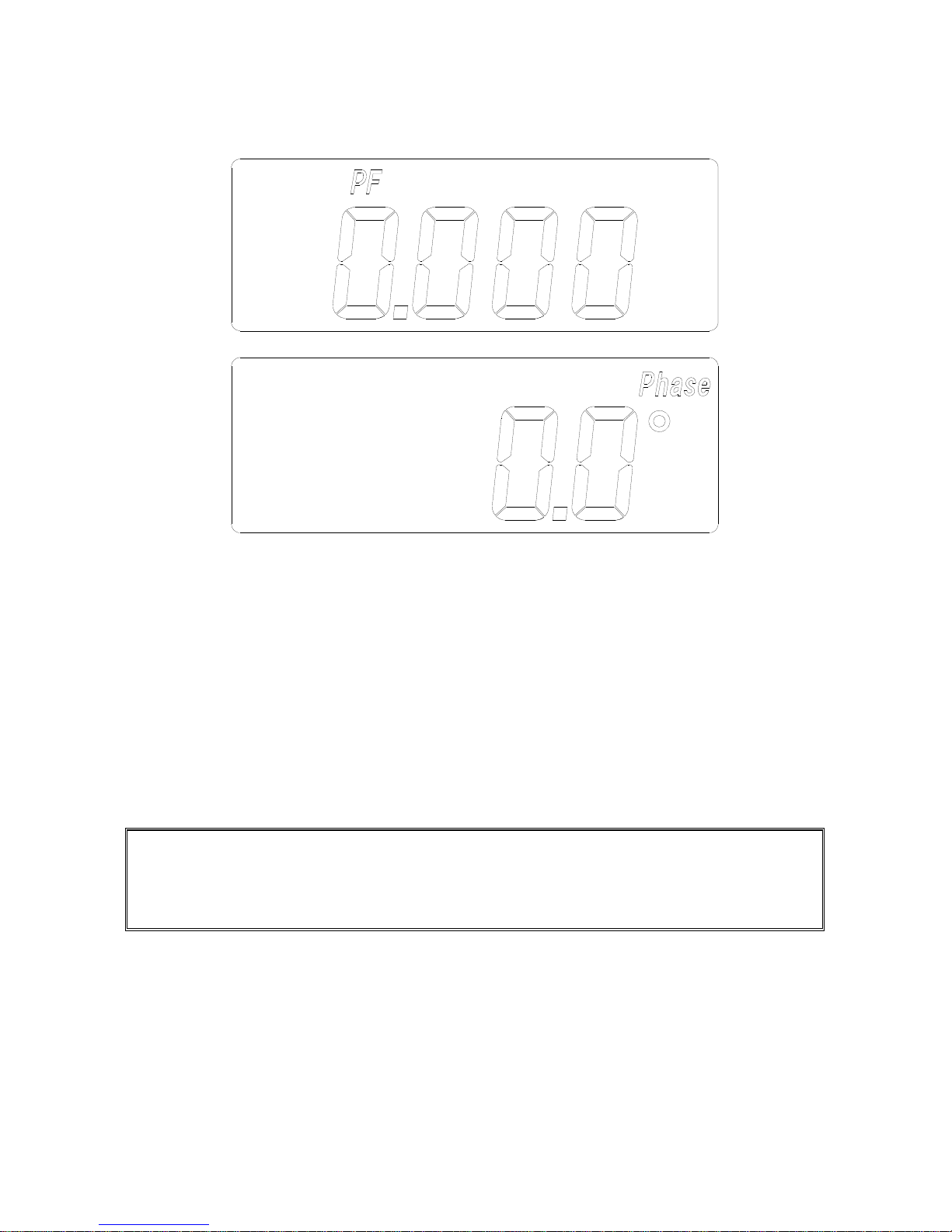
e. Press the FUNC button three times to display PF from 0.000 to 1.000.
f. Press the FUNC button four times to display phase angle (Φ) from –180° to
+180°.
NOTE: To display phase angle (Φ) from 0 to 360, hold the ▲ button, then turn the
power on. Once the tester is turned on in this way, the tester will display phase
angle from 0 to 360° (when phase angle function is selected).
Page 22
19
III.3.4. Horse Power (H.P.)
a. Connect the test leads to the voltage source in parallel with the load.
b. Clamp on one of the wire to the load. The current should flow from the front of
the tester to the side of the battery cover.
c. Select proper Watt range (W-mA or W-A).
d. The value of mW, W, or KW will be displayed in LCD. The unit of watt is
automatically scaled.
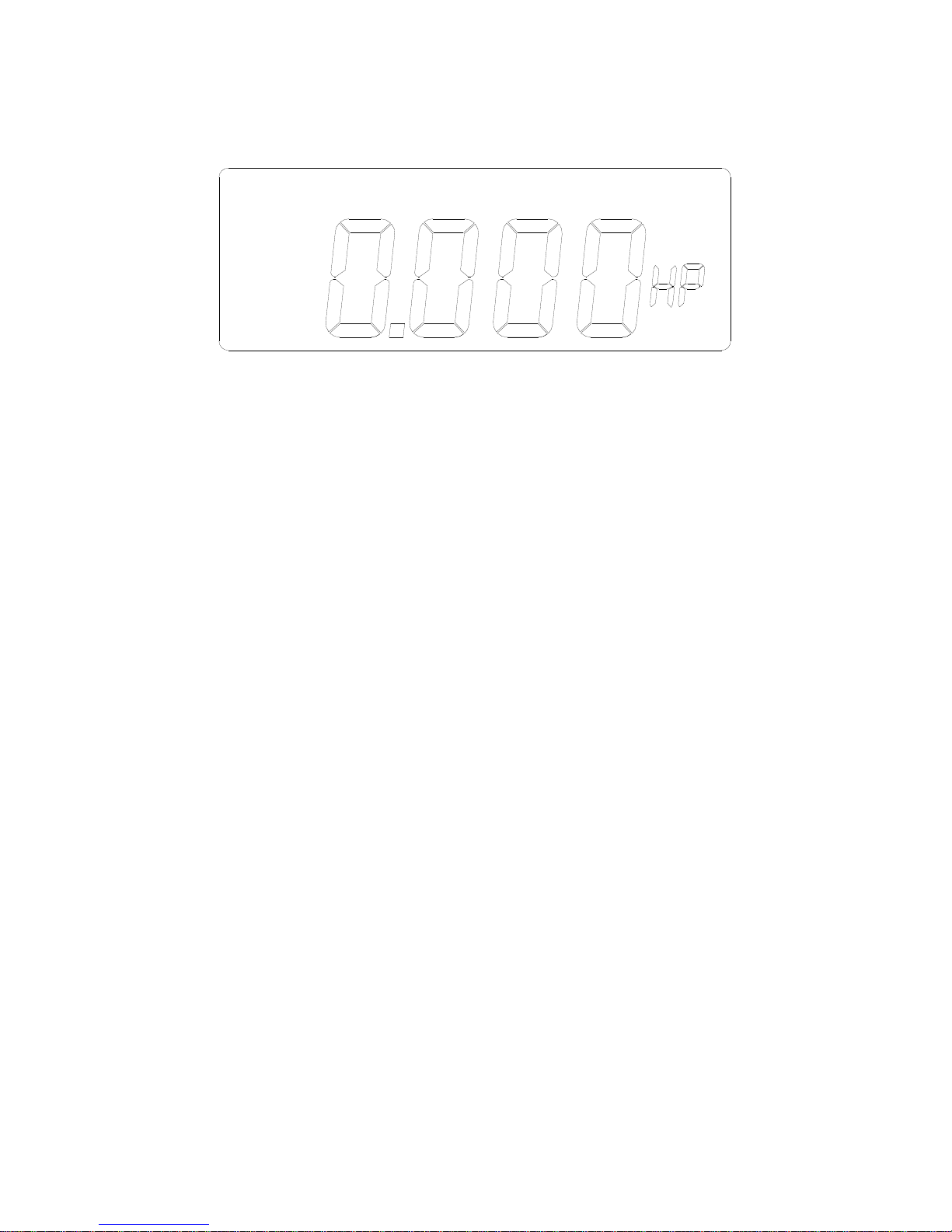
e. Press the FUNC button five times to display power in the unit of HP.
III.3.5. Energy (mWH, WH, or KWH)
a. Connect the test leads to the voltage source in parallel with the load.
b. Clamp on one of the wire to the load. The current should flow from the front of
the tester to the side of the battery cover.
c. Select proper Watt range (W-mA or W-A).
d. The value of mW, W, or KW will be displayed in LCD. The unit of watt is
automatically scaled.
e. Press the FUNC button six times. A character of H is displayed in front of
reading to indicate energy (mWH, WH, or KWH). The energy is displayed in
6 digits (Four large digits and two small digits). The energy will be reset to
zero at the beginning when this function is selected.
Page 23
20
III.4 Measurement of the Balanced 3 Phase AC Power Quality (21, 23)
3
a. Connect the black test lead to the voltage L3, and connect the red test lead to
L1.
b. Clamp on one of the wire to L2. The current should flow from the front of the
tester to the side of the battery cover.
c. Select proper Watt range (W-mA or W-A).
d. Press the ▲ button to select balanced 3Φ. A symbol of “3Φ” will be shown in
LCD.
e. The value of mW, W, or KW will be displayed in LCD. The unit of watt is
automatically scaled.
NOTE: Users can also obtain the measurements of VA, VAR, PF, Phase Angle,
HP, and energy (WH) for balanced 3Φ power system. The operations are the same
as the measurements for the single-phase power system.
Page 24
21
III.5 Measurement of the Balanced 3 Phase Sequence (21, 23)
L1
L3
L1
L2
L3
T
u
r
e
R
M
S
A
U
T
O
-
P
O
W
E
R
-
O
F
F
3
+
L1
L2
L3
3
L3
L2
L1
3
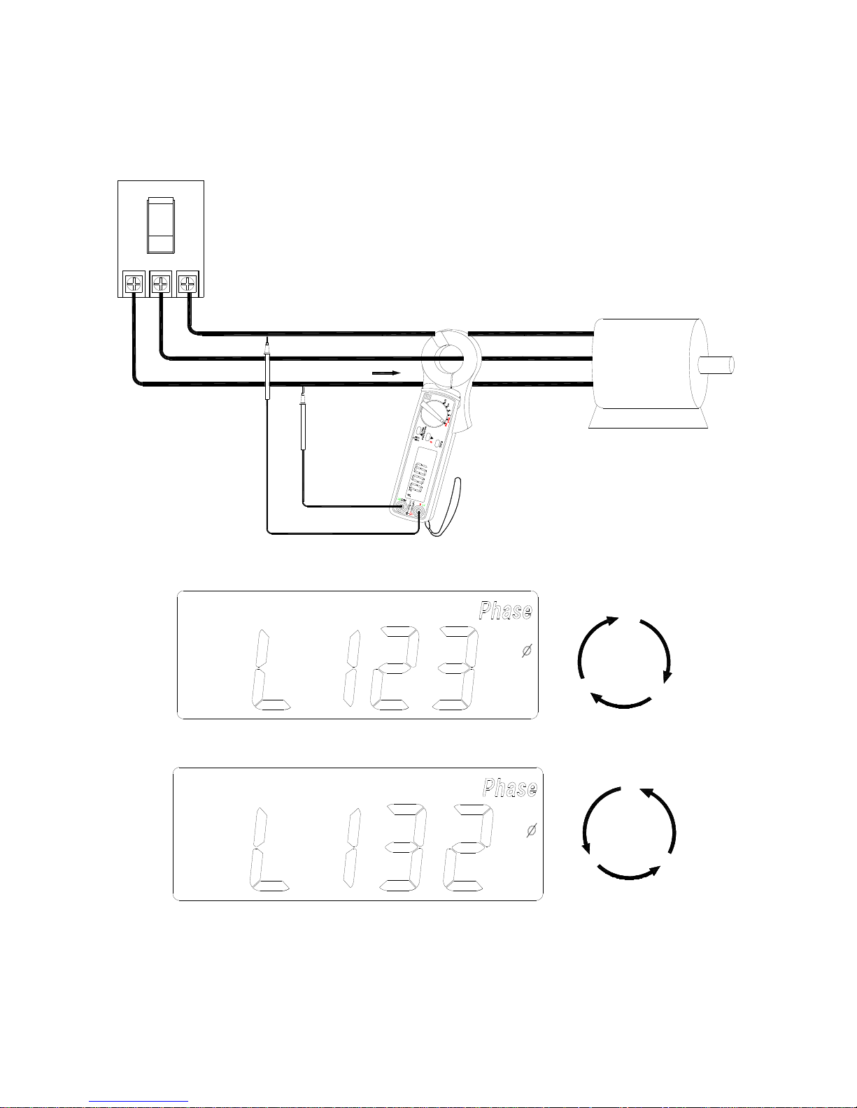
a. Hold the ▼ button, and then turn the power on. Set the rotary switch at the
W-mA or W-A position.
b. Connect the black test lead to the voltage L3, and connect the red test lead to
Page 25

22
L1.
c. Clamp on to the wire of L2. The current should flow from the front of the tester to
the side of the battery cover.
d. Press the ▲ button to select 3 phase power system. A symbol of 3Φ will be
shown in LCD.
e. Press the FUNC button to select phase angle function. The LCD will show L123
to indicate the clockwise sequence. Or the LCD will show L132 to indicate
counter clockwise sequence.
IV. SET THE CT RATIO
To set the CT ratio, hold the FUNC button, and then turn the power on. A symbol
of “CT” will be shown in LCD. The default value of CT is 1. To change the CT
ratio, users can press the ▲ or ▼ button to increment or decrement the value by
1. Holding the ▲ or ▼ button will speed up the process of incrementing or
decrementing.
To exit the setting of CT ratio, press the FUNC button.
V. DISABLE AUTO-POWER-OFF
The tester has an auto-power-off function. The tester will turn the power off after
power is turned on for 30 minutes. To disable the auto power off function, hold
the FUNC button for more than 2 seconds. A beep sound will be heard to
indicate that the auto power off function is disabled.
For Model 23, users can not disable the auto-power-off function in the
measurement of THD.
Page 26
23
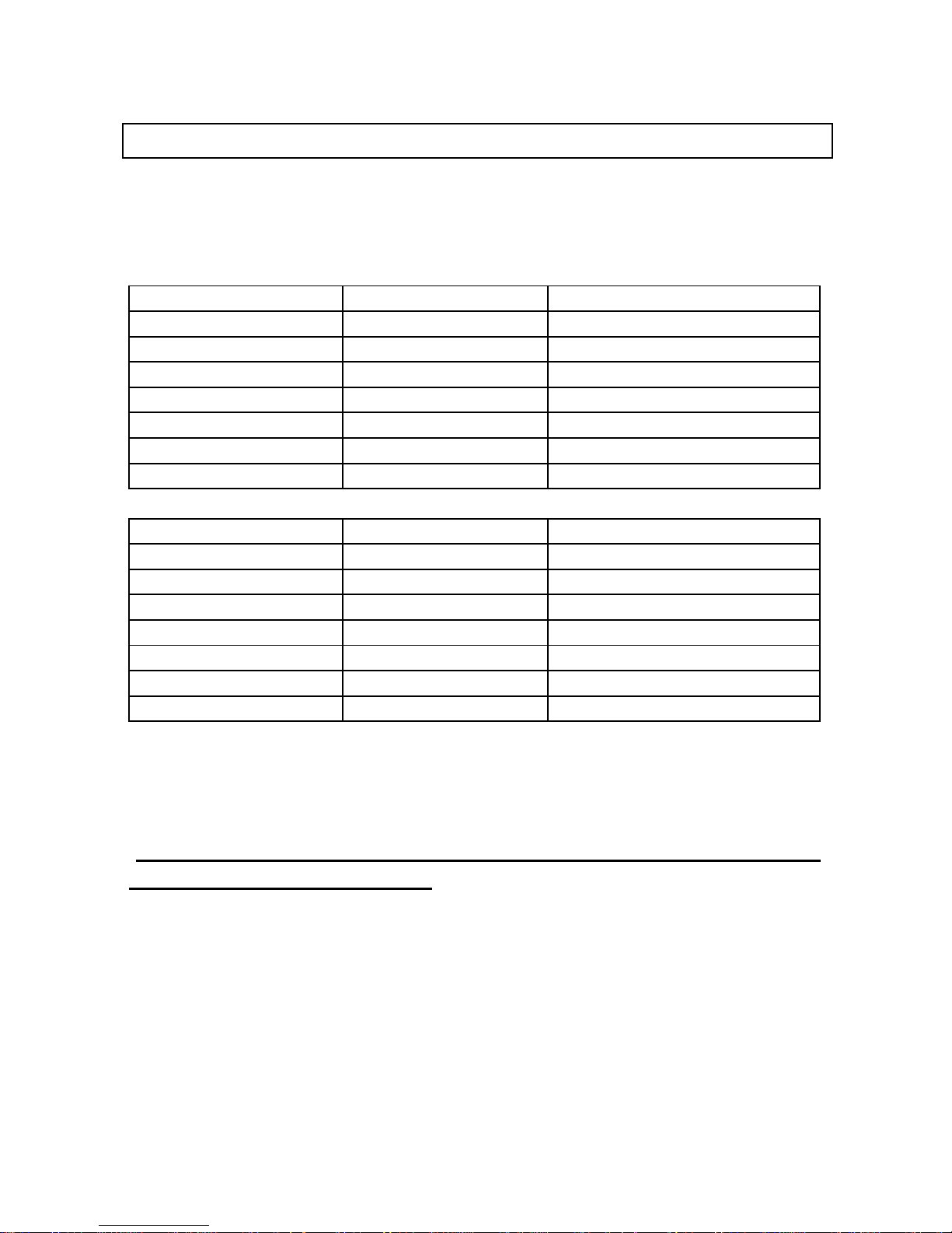
VI. SPECIFICATIONS (23°C±5°C)
AC Watt (50 or 60 Hz, PF 0.6 to 1. CT = 1, Voltage is greater than AC 4V, Current is
greater than AC 1mA for mA range, and Current is greater than AC 0.04A for A
range. Specification applies to continuous waveforms)
Model 21
Range (0 to 30A) Resolution Accuracy of Readings
1, 2
0.050 – 9.999 W 0.001W ±2% ± 0.025W
10.00 – 99.99 W 0.01W ±2% ± 0.25W
100.0 – 999.9 W 0.1W ±2% ± 2.5W
1.000 – 9.999 KW 0.001 KW ±2% ± 0.025KW
10.00 – 99.99 KW 0.01 KW ±2% ± 0.25KW
100.0 – 999.9 KW 0.1 KW ±2% ± 2.5KW
1000 – 9999 KW 1 KW ±2% ± 25KW
Model 23
Range (0 to 60A) Resolution Accuracy of Readings
1, 2
0.050 – 9.999 W 0.001W ±2% ± 0.025W
10.00 – 99.99 W 0.01W ±2% ± 0.25W
100.0 – 999.9 W 0.1W ±2% ± 2.5W
1.000 – 9.999 KW 0.001 KW ±2% ± 0.025KW
10.00 – 99.99 KW 0.01 KW ±2% ± 0.25KW
100.0 – 999.9 KW 0.1 KW ±2% ± 2.5KW
1000 – 9999 KW 1 KW ±2% ± 25KW
1
For CT ≠1, the accuracy in percentage is the same (±2%). But the additional
wattage should be multiplied by the CT ratio.
For example, ±0.025W becomes ±0.025W * CT ratio
2
If Auto Hz is selected, the AC voltage must be greater than 50V, and add
2°
phase angle error to the accuracy.
Page 27
24
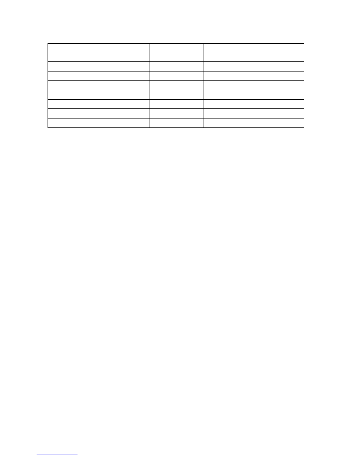
Model 21 Range (30 – 50A)
Model 23 Range (60 – 100A)
Resolution Accuracy
3, 4
0.050 – 9.999 W 0.001W ±2% of VA ± 5dgts
10.00 – 99.99 W 0.01W ±2% of VA ± 5dgts
100.0 – 999.9 W 0.1W ±2% of VA ± 5dgts
1.000 – 9.999 KW 0.001 KW ±2% of VA ± 5dgts
10.00 – 99.99 KW 0.01 KW ±2% of VA± 5dgts
100.0 – 999.9 KW 0.1 KW ±2%of VA ± 5dgts
1000 – 9999 KW 1 KW ±2% of VA ± 5dgts
3
For CT ≠1, the accuracy in percentage is the same (±2%). But the additional
digits should be multiplied by the CT ratio.
For example, ±5 digits becomes ±5 digits * CT ratio
4
If Auto Hz is selected, the AC voltage must be greater than 50V.
Range of CT Ratio: 1 to 250
H.P. (Horse Power)
1 H.P. = 746 W
AC Apparent Power (VA, from 0.000VA to 9999 KVA)
VA = V r.m.s. x A r.m.s
AC Reactive Power (VAR, from 0.000 VAR to 9999 KVAR)
VAR = √(VA
2
– W2)
AC Active Energy (mWH, WH, or KWH, from 0 mWH to 999,999 KWH)
WH = W * Time (in hours)
Page 28
25
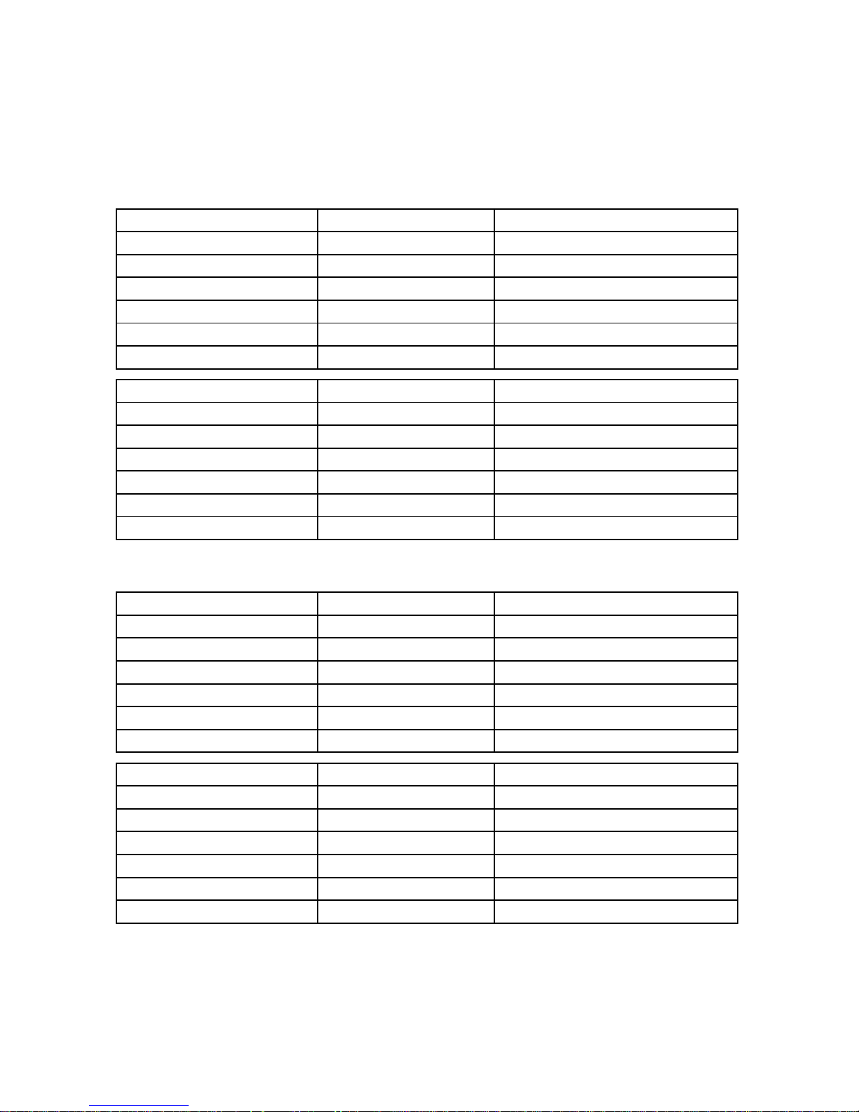
AC Current (Accuracy is of Reading, Auto Range, True RMS, Crest Factor < 4,
CT=1, Max. peak values 880mADC for mA range, 73.5ADC for A range, and
Overload Protection AC 600A)
Model 19,21
Range Resolution Accuracy (50/60Hz)
5, 6
0.5 – 60mA 0.01mA ±0.5% ± 5dgts
60 – 100mA 0.01mA ±0.5% ± 50dgts
100 – 600 mA 0.1 mA ±0.5% ± 5dgts
0.05 – 3 A 0.001 A ±0.5% ± 5dgts
3 – 30 A 0.01 A ±0.5% ± 5dgts
30 – 50 A 0.01 A ±1.0% ± 5dgts
Range Resolution Accuracy (45-1KHz)
5, 6
0.5 – 60mA 0.01mA ±1.5% ± 5dgts
60 – 100mA 0.01mA ±1.5% ± 50dgts
100 – 600 mA 0.1 mA ±1.5% ± 5dgts
0.05 – 3 A 0.001 A ±1.5% ± 5dgts
3 – 30 A 0.01 A ±1.5% ± 5dgts
30 – 50 A 0.01 A ±1.5% ± 5dgts
Model 23
Range Resolution Accuracy (50/60Hz)
5, 6
0.5 – 60mA 0.01mA ±0.5% ± 5dgts
60 – 100mA 0.01mA ±0.5% ± 50dgts
100 – 600 mA 0.1 mA ±0.5% ± 5dgts
0.05 – 3 A 0.001 A ±0.5% ± 5dgts
3 – 30 A 0.01 A ±0.5% ± 5dgts
30 – 90 A 0.01 A ±1.0% ± 5dgts
Range Resolution Accuracy (45-1KHz)
5, 6
0.5 – 60mA 0.01mA ±1.5% ± 5dgts
60 – 100mA 0.01mA ±1.5% ± 50dgts
100 – 600 mA 0.1 mA ±1.5% ± 5dgts
0.05 – 3 A 0.001 A ±1.5% ± 5dgts
3 – 30 A 0.01 A ±1.5% ± 5dgts
30 – 90 A 0.01 A ±1.5% ± 5dgts
5
For CT ≠1, the accuracy in percentage is the same (±0.5%). But the
additional digits should be multiplied by the CT ratio.
Page 29
26
For example, ±5 digits becomes ±5 digits * CT ratio
6
If Auto Hz is selected, the AC current must be greater than 10mA for mA
range, and greater than 1A for A range.
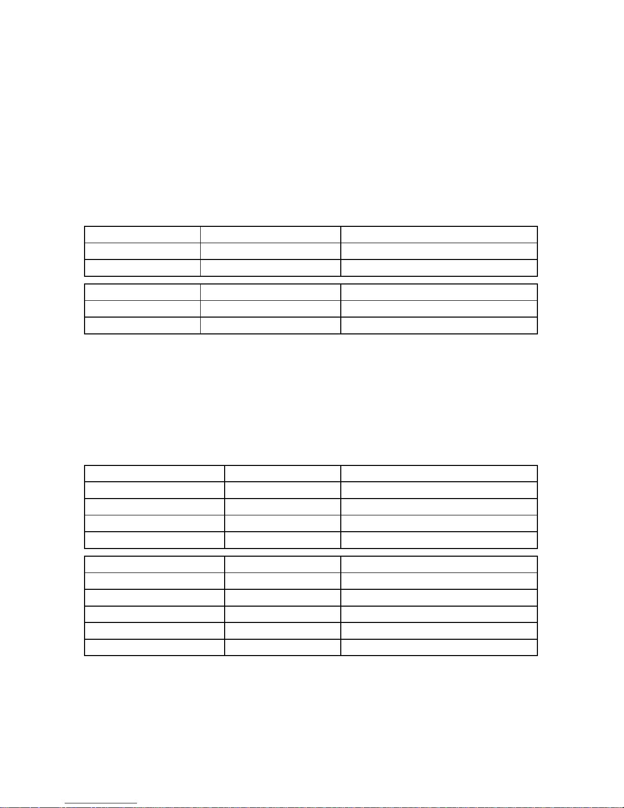
AC Voltage (Accuracy is of reading, Auto Range, True RMS, Crest Factor < 4, Input
Impedance 10 MΩ, Max peak value 860VDC, and Overload Protection AC 800V)
Model 19, 21, 23
Range Resolution Accuracy (50/60Hz)
7
5V – 250 V 0.1 V ±0.5% ± 5dgts
250 V – 600 V 0.1 V ±0.5% ± 5dgts
Range Resolution Accuracy (45-1KHz)7
5V – 250 V 0.1 V ±1.5% ± 5dgts
250 V – 600 V 0.1 V ±1.5% ± 5dgts
7
If Auto Hz is selected, the AC voltage must be greater than 50V.
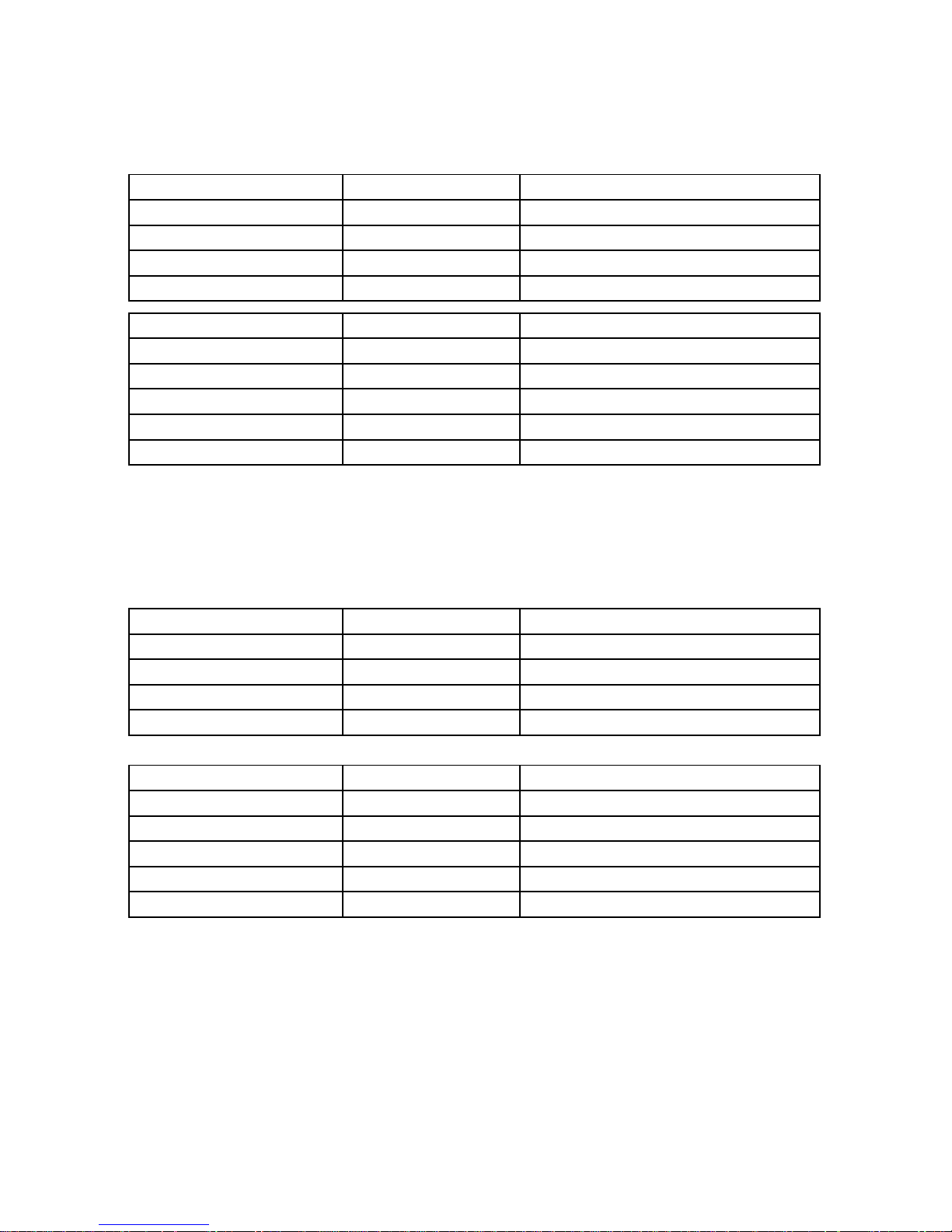
Harmonics of AC Voltage in Percentage (1 to 99
th
order, minimum voltage at 50
or 60 Hz is greater than AC 80V. If the voltage is 0 at 50 or 60 Hz, all the percentage
(%) display is 0).
Range (Model 19, 21) Resolution Accuracy
1 – 10th 0.1 % ±1% of reading ±1%
11 – 20th 0.1 % ±5% of reading ±1%
21 – 50th 0.1 % ±15% of reading ±1%
51 - 99th 0.1 % ±35% of reading ±1%
Range (Model 23) Resolution Accuracy
1 – 10th 0.1 % ±0.7% of reading ±1%
11 – 20th 0.1 % ±2% of reading ±1%
21 – 50
th
(A range) 0.1 % ±5% of reading ±1%
21 – 50th (mA range) 0.1 % ±10% of reading ±1%
51 - 99th 0.1 % ±35% of reading ±1%
Page 30
27
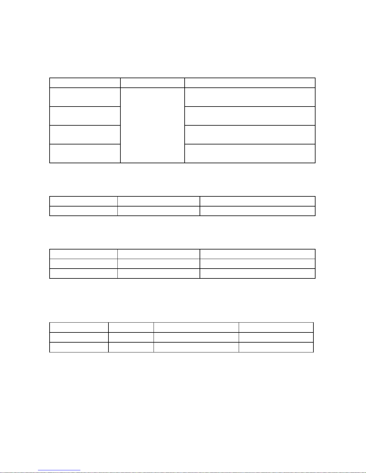
Harmonics of AC Voltage in Magnitude (1 to 99
th
order, minimum voltage at 50 or
60 Hz is greater than AC 80V)
Range (Model 19, 21) Resolution Accuracy
1 – 10th 0.1 V ±1% of reading ±7dgts
11 – 20th 0.1 V ±5% of reading ±7dgts
21 – 50th 0.1 V ±15% of reading ±7dgts
51 - 99th 0.1 V ±35% of reading ±7dgts
Range (Model 23) Resolution Accuracy
1 – 10th 0.1 V ±0.7% of reading ±7dgts
11 – 20th 0.1 V ±2% of reading ±7dgts
21 – 50
th
(A range) 0.1 V ±5% of reading ±7dgts
21 – 50th (mA range) 0.1 V ±10% of reading ±7dgts
51 - 99th 0.1 V ±35% of reading ±7dgts
Harmonics of AC Current in Percentage (1 to 99
th
order, minimum current at 50
or 60 Hz is greater than 100mA for mA range, and greater than 1A for A range. If the
current is 0 at 50 or 60 Hz, all the percentage (%) display is 0)
Model 19, 21
Range Resolution Accuracy
1 – 10th 0.1 % ±1% of reading ±1%
11 – 20th 0.1 % ±5% of reading ±1%
21 – 50th 0.1 % ±15% of reading ±1%
51 - 99th 0.1 % ±35% of reading ±1%
Model 23
Range Resolution Accuracy
1 – 10th 0.1 % ±0.7% of reading ±1%
11 – 20th 0.1 % ±2% of reading ±1%
21 – 50
th
(A range) 0.1 % ±5% of reading ±1%
21 – 50th (mA range) 0.1 % ±10% of reading ±1%
51 - 99th 0.1 % ±35% of reading ±1%
Page 31
28
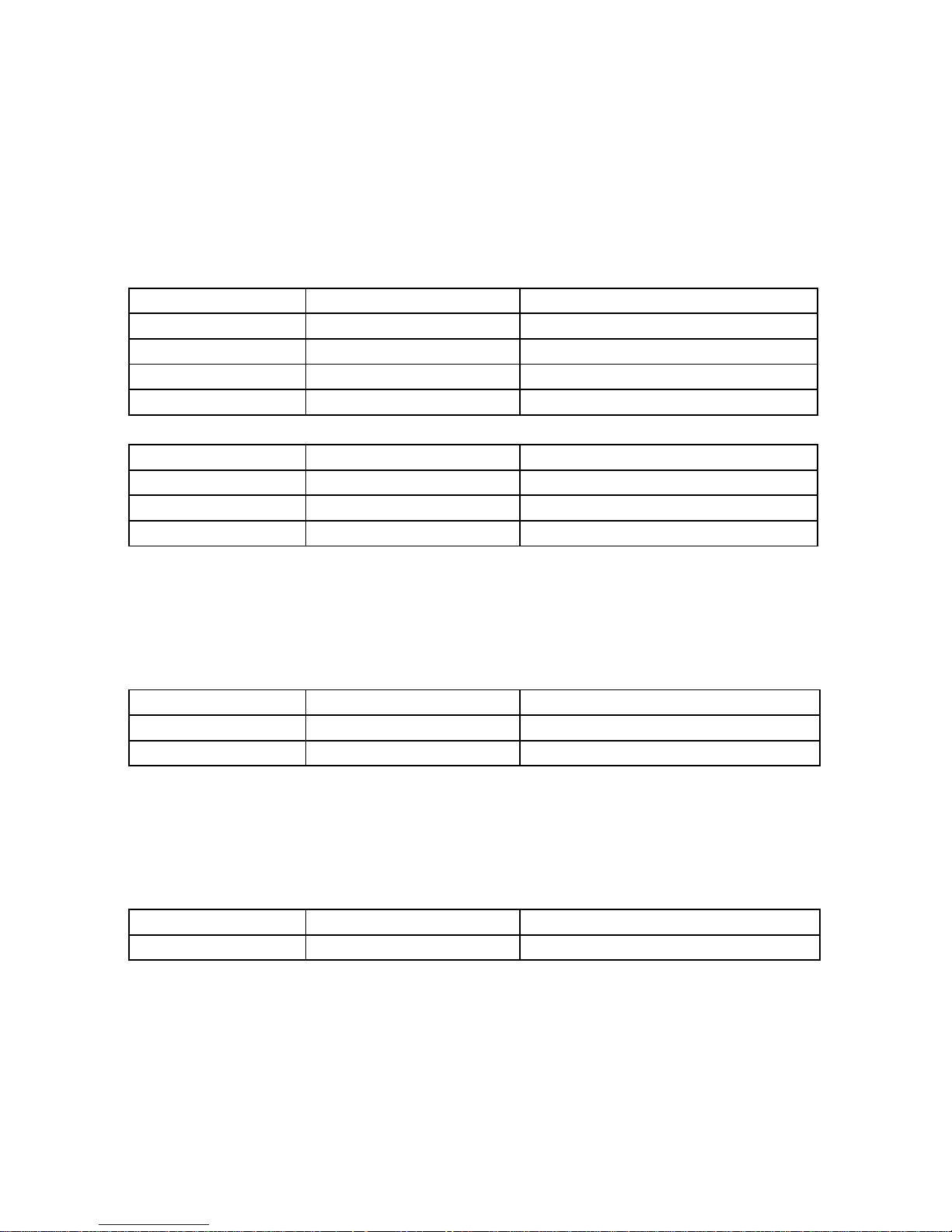
Harmonics of AC Current in Magnitude (1 to 99
th
order, minimum current at 50 or
60 Hz is greater than 100mA for mA range, and greater than 1A for A range)
Model 19, 21, 23
Range Resolution Accuracy
1 – 10th reading in mA: ±1% of reading ±2mA
reading in A: ±1% of reading ±0.3A
11 – 20th reading in mA: ±7% of reading ±2mA
reading in A: ±7% of reading ±0.3A
21 – 50th reading in mA: ±15% of reading ±3mA
reading in A: ±15% of reading ±0.3A
51 - 99th
0.01mA /
0.1mA /
0.001A /
0.01A
reading in mA: ±35% of reading ±3mA
reading in A: ±35% of reading ±0.3A
Power Factor (PF, ACV > 4V, AC mA > 1mA, AC A > 0.04A, Watt > 50 digits)
Model 21, 23
Range Resolution Accuracy
0.000 – 1.000 0.001 ±0.04
Phase Angle (Φ, 50 or 60Hz)
Model 21, 23
Range Resolution Accuracy
-180° to 180° 0.1° ± 2°
0° to 360° 0.1° ± 2°
If function of AUTO Hz is selected, add 2° error to the accuracy.
Frequency (Hz)
Model 19, 21, 23
Range Resolution Accuracy of Readings Allowed Input
mA(45 – 65Hz) 0.1Hz ± 0.5Hz 20mA to 1.2A
A(45 - 65Hz) 0.1Hz ± 0.5Hz 1A to 100A
Sensitivity (PROVA 19, 21): > 20mA for mA range, > 1A for A range, and > 50V
Sensitivity (PROVA 23): > 20mA for mA range, > 3A for A range, and > 50V
Page 32
29
Total Harmonic Distortion (THD-F with respect to the first (fundamental)
harmonics, min. value in the range from 45 to 65Hz is greater than AC 80V, greater
than 1A for A range, and greater than 100mA for mA range. Calculation is done over
1 to 50
th
Harmonics. If the voltage or current is 0 in the range from 45 to 65Hz, all the
percentage (%) display is 0)
Model 19, 21
Range (45~65Hz) Resolution Accuracy
0.0 – 10.0 % 0.1% ± 2%
10.0 – 40% 0.1% ±5% of reading ± 5%
40 – 100% 0.1% ±10% of reading ± 10%
100 – 999.9% 0.1% ±20% of reading
Model 23
Range (45~65Hz) Resolution Accuracy
0.0 – 20.0 % 0.1% ± 2%
20.0 – 100% 0.1% ±3% of reading ± 5%
100 – 999.9% 0.1% ±10% of reading ±10%
Peak Value of AC Periodic Voltage (peak value > 10V) or AC Periodic Current
(peak value > 10mA for mA range and peak value > 0.5A for A range) for
continuous waveform except for square wave:
Model 19, 21, 23
Range Sampling Time Accuracy of Reading
50 Hz 39 μs ± 5% ± 30 digits
60 Hz 33 μs ± 5% ± 30 digits
Crest Factor (C.F.) of AC Voltage (peak value > 10V) or AC Current (peak value
> 10mA for mA range and peak value > 0.5A for A range) for continuous
waveform except for square wave:
Model 19, 21, 23
Range (45~65Hz) Resolution Accuracy of Readings
1.00 – 99.99 0.01 ± 5% ± 30 digits
Page 33

30
Indoor Use
Conductor Size: 30mm (approx.)
Battery Type: two 1.5V SUM-3
Display: 4+2+2 digits LCD
Range Selection: Auto
Overload Indication: OL
Power Consumption: 10mA (approx.)
Low battery Indication:
Auto-Power-Off: 30 minutes after power-on
Update Time: 2 times/sec. (display)
No. Of Samples per Period 512 (voltage or current)
256 (power)
Temperature Coefficient
(<18 or ℃ >28 ): ℃ 0.15 x (Specified Accuracy) / ℃
Operating Temperature: -10°C to 50°C
Operating Humidity: less than 85% relative
Altitude: up to 2000M
Storage Temperature: -20°C to 60°C
Storage Humidity: less than 75% relative
Dimension: 210mm (L) x 62mm (W) x 35.6mm (H)
8.3" (L) x 2.5" (W) x 1.4" (H)
Weight: 200g (battery included)
Accessories: test leads
Carrying bag x 1
Users manual x 1
Batteries 1.5V x 2
Option: Alligator clips
Page 34
31
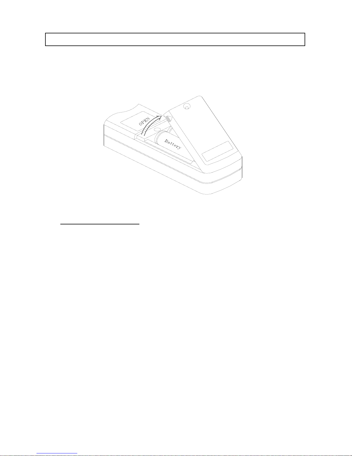
VII. BATTERY REPLACEMENT
When the low battery symbol is displayed on the LCD, replace the old batteries with
two new batteries.
A. MUST Turn the power off
and remove the test leads from the clamp meter.
B. Remove the screw of the battery compartment.
C. Lift and remove the battery compartment.
D. Remove the old batteries.
E. Insert two new 1.5V SUM-3 batteries.
F. Replace the battery compartment and secure the screw.
Page 35

32
VIII. MAINTENANCE & CLEANING
Servicing not covered in this manual should only be performed by qualified
personnel. Repairs should only be performed by qualified personnel.
Periodically wipe the case with a damp cloth and detergent; do not use abrasives or
solvents.
Address of Agent, Distributor, Importer, or Manufacturer
 Loading...