

Page 1

0
Document Revision: (2)
0
0
Product Manual
PR-4
t
Page 2

1
Document Revision: (2)
1
1
Product Manual
PR-4
Disclaimer
Printed copies of this manual are not controlled.
This document is intellectual property of Pro Tune Electronic Systems. This manual cannot be reproduced,
distributed or transmitted by any means, electronic or printed, without the proper authorization of Pro Tune
Electronic Systems.
The company, its employees and resellers are not responsible for the incorrect use of the information,
inaccuracies or omissions in this document.
Pro Tune reserves the right to make changes to this document without prior notice.
Page 3

2
Document Revision: (2)
2
2
Product Manual
PR-4
Congratulations!
You just bought a product from Pro Tune. We thank you for your trust in our products, which are produced
following stringent international standards together with highly rigorous quality control, so that you receive a
superior product in performance, finish and functionality.
Our products are 100% manufactured in Brazil, from the assembly of the electronic components, through
programming and finishing with the case machined in aluminum, which gives a durable and professional look to the
products.
We hope you have a great experience with Pro Tune products, and we are available to answer any questions
and supply any technical support you might have in installing or operating our products.
Page 4

3
Document Revision: (2)
3
3
Product Manual
PR-4
Glossary of terms and abbreviations
CAN – Controller Area Network .
CKP – Crankshaft Position Sensor.
CMP – Camshaft Position Sensor.
DATALOG – Sample set of readings from a group of sensors, saved on a device with memory.
ECU – Engine Control Unit.
ET – Engine Temperature.
GPS – Global Position System.
IAT – Intake Air Temperature.
MAF – Mass Air Flow.
MAP – Manifold Absolute Pressure.
NTC – Negative Temperature Coefficient.
OBD II – On-Board Diagnostic II.
PEAK & HOLD – Activation strategy for low impedance fuel injectors.
PINOUT – Diagram, or pin configuration of a device.
TDC – Top Dead Center – Highest position of the piston inside the cylinder.
PP – Pedal Position Sensor.
PWM – Pulse Width Modulation.
RGB – Red Green Blue
SHIFT LIGHTS – Progressive lights with activation linked to engine speed.
TDL – Touch Dash Logger.
TP – Throttle Position.
TPS – Throttle Position Sensor.
USB - UNIVERSAL SERIAL BUS.
Page 5

4
Document Revision: (2)
4
4
Product Manual
PR-4
Summary
1. Overview 6
Harness Reference Table 7
2. Read Before Installing 9
3. Instalation Diagram 10
3.1 – Basic Wiring: 10
4.1 –Inputs 11
Crank and Camshaft Possiton Sensors 11
Manifold Absolute Pressure (MAP) 12
Throttle Position (TP) 12
Engine and Intake Air Temperatures Sensors 13
Lambda Sensor NTK UEGO 14
Mass Air Flow– MAF 14
Pedal Position Sensor 15
Vehicle Speed Sensor 15
Generic Potentiometer (Gear Position, Steering Angle, etc) 16
Load on Shift Lever 17
Oil / Fuel Pressure 18
Injectors – Sequential 18
Injectors – 8 Cilinders Semi-Sequential 19
Injectors – Secondary Injector Rail 19
Injectors – Secondary Injector Rail Semi-Sequential 20
Ignition Coils without Integrated Driver 20
Dual Ignition Coils without Integrated Driver Semi-Sequential 21
Triple Ignition Coils without Integrated Driver Semi-Sequential 21
Ignition Coils with Integrated Driver 22
Electric Fan 22
Electronic Throttle Control 23
Switch 24
Solenoid Valve 24
Tachometer Output 25
4. Sync 26
Page 6

5
Document Revision: (2)
5
5
Product Manual
PR-4
Trigger Wheel for Crank Position and Engine Speed: 26
Distributor for Rotation and Phase Reading: 28
Distributor only for phase reading: 28
Camshaft Position Sensor for Phase Reading: 28
Page 7
6
Document Revision: (2)
6
6
Product Manual
PR-4
1. Overview
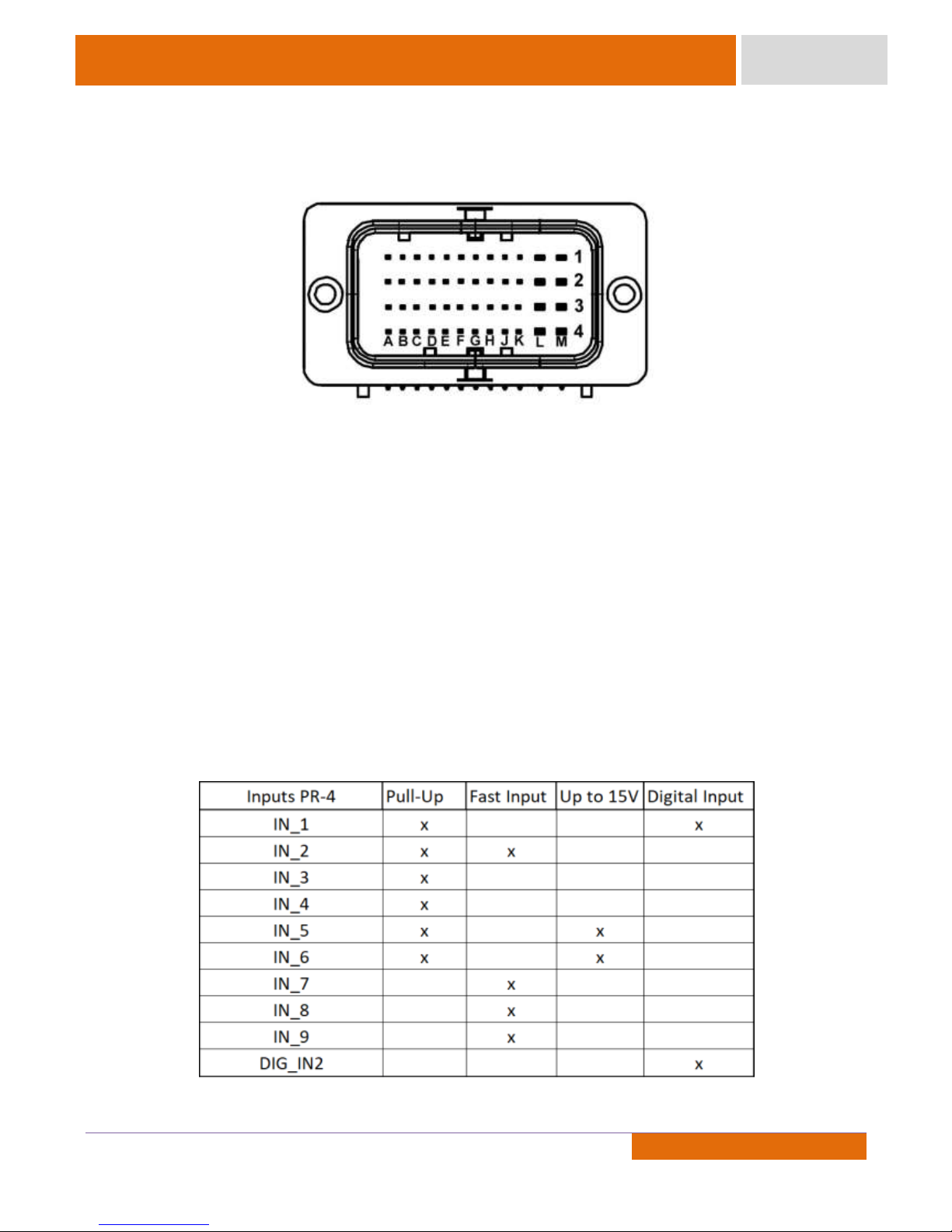
The PR-4 ECU features a 48-pin waterproof connector. Its image can be seen in the figure below.
This connector uses a letter and number system to identify each pin, with the columns being identified by
letters A to M and lines identified by numbers 1 to 4. In addition to this alphanumeric label, all Pro Tunes pre-wired
harness has cables with identification printed on its cover.
The PR-4 ECU has an integrated USB port on the top where an A-B USB cable can be plugged into the ECU for
configuration. In addition, the ECU has CAN communication used to communicate with various CAN devices.
Pro Tune ECU has several functions, for example, Lambda Control, Boost Control, and others. Therefore, the
factory-enabled functions on the ECU depends on whether a package (Advanced or Plus) is chosen at the purchase
moment. If there is an interest in using new functions, the user can contact Pro Tune to purchase only the activation
code needed, not requiring the exchange of the product or the installation of extra modules.
Before proceeding to the electrical installation, it is essential to choose the inputs to which the sensors will
be connected to the ECU. On the inputs equipped with pull-up resistors, it is possible to operate in Temperature
Mode to connect temperature sensors and buttons with ground-based operation.
The fast inputs are suitable for reading signals of sensors that have a high rate of variation, such as throttle
position, pedal position, intake pressure sensor and mass flow sensor. Inputs up to 15 V are suitable for sensors with
signal amplitude greater than 5V. These inputs can be used to, for example, read the trigger status of a 12V switch.
The digital inputs are those that support frequency signals. At these inputs, for example, wheel speed sensors can be
connected.
Page 8
7
Document Revision: (2)
7
7
Product Manual
PR-4
Harness Reference Table
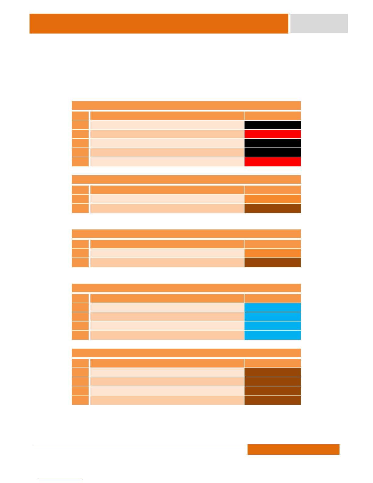
The Functions of each wire and its respective pin in the connector can be seen in the following table.
PR-4 - Power
Pin
Function
Label
L2
Sensor Ground
No Label
K3
Sensor 5V
SENSOR 5V
L3
Power Ground
No Label
L4
Power Ground
No Label
M4
12V Power
+12V_SWITCH
PR-4 – Crank Position Sensor
Pin
Function
Label
F4
Positive Input - Crank Position Sensor (CKP+)
No Label
G4
Negative Input – Crank Position Sensor (CKP-)
No Label
*The cables described above are part of a triple shielded black cable with the label CKP.
PR-4 – Camshaft Position Sensor
Pin
Function
Label
H4
Positive Input – Camshaft Position Sensor (CMP+)
No Label
J4
Negative Input – Camshaft Position Sensor (CMP-)
No Label
* The cables described above are part of a triple shielded black cable with the label CMP.
PR-4 – Injectors
Pin
Function
Label
A1
Injector 1 Output
INJ_1
B1
Injector 2 Output
INJ_2
C1
Injector 3 Output
INJ_3
D1
Injector 4 Output
INJ_4
PR-4 – Ignition
Pin
Function
Label
H1
Ignition 1 Output
IGN_1
J1
Ignition 2 Output
IGN_2
K1
Ignition 3 Output
IGN_3
H2
Ignition 4 Output
IGN_4
Page 9
8
Document Revision: (2)
8
8
Product Manual
PR-4
PR-4 – Auxiliaries Inputs
Pin
Function
Label
C2
Auxiliary Input 1
IN_1
D2
Auxiliary Input 2
IN_2
E2
Auxiliary Input 3
IN_3
F2
Auxiliary Input 4
IN_4
G2
Auxiliary Input 5
IN_5
G3
Auxiliary Input 6
IN_6
F3
Auxiliary Input 7
IN_7
H3
Auxiliary Input 8
IN_8
J3
Auxiliary Input 9
IN_9
E4
Digital Input 2
DIG_IN2
PR-4 - Auxiliaries Outputs
Pin
Function
Label
G1
Auxiliary Output 1
OUT_1
F1
Auxiliary Output 2
OUT_2
E1
Auxiliary Output 3
OUT_3
L1
Electronic Throttle Control Output (positive)
ETC+
M1
Electronic Throttle Control Output (negative)
ETC-
M3
Auxiliary Output 6
OUT_6
K4
Main Relay Output
OUT_MAIN_RELAY
PR-4 – Lambda Sensor
Pin
Function
Label
A3
Lambda – Heater Ground
LAMBDA1_HT-
B3
Lambda – Reference
LAMBDA1_SENSOR
REF
C3
Lambda – Calibration
LAMBDA1_RCAL
D3
Lambda – Ipump
LAMBDA1_IP
E3
Lambda – Nernst Cell
No Label
PR-4 – Communication
Pin
Function
Label
A2
Pro Tune CAN Low
CAN_LOW
B2
Pro Tune CAN High
CAN_HIGH
Page 10

9
Document Revision: (2)
9
9
Product Manual
PR-4
2. Read Before Installing
Pro Tune products are developed with attention to robustness and reliability. However, some care is
required when installing the product
1 – Internal combustion engines are very sensible devices and in case of accidents present lethal risks. It is
very important that all care is taken, such as individual operator protection, fire prevention and fire fighting,
prior checking of fuels and lubricants, as well as the installation, maintenance and operation done only by
qualified people.
2 – Place the wiring harness as far as possible from the ignition circuit.
3 – Avoid installing the ECU in the engine compartment.
4 – Place the product in an accessible location for the USB cable, preferably with the main connector facing
down.
5 – When the wiring is done, keep unused (White) cables intact and connect them ti the negative battery
terminal.
6 – Make sure the intake pressure measurement hose attachment is securely fastened. Poorly fixed or
leaking hoses result in incorrect reading of intake pressure, which can cause serious engine damage.
7 – The intake hose must always be connected between the throttle body and the engine.
8 – If the triple cable named CMP is not used, do not cut it and isolate its wires individually.
9- Always check the wiring diagram of each sensor or actuator before finishing the harness and turning on
the ECU.
10- Pay attention to the safe grounding of the engine block and the vehicle chassis.
11-Pay attention to the sensors ground (Pin L2), with black cable, which should not be connected to the
battery or to the chassis of the vehicle. It is a ground wire for sensors, which must be used exclusively to
connect the negative terminal of the sensors.
12- Use suitable fuses in the power circuit.
13- Use suppressive spark plug cables and resistive type spark plugs.
14- Use shielded USB communication cables.
Page 11
10
Document Revision: (2)
10
10
Product Manual
PR-4
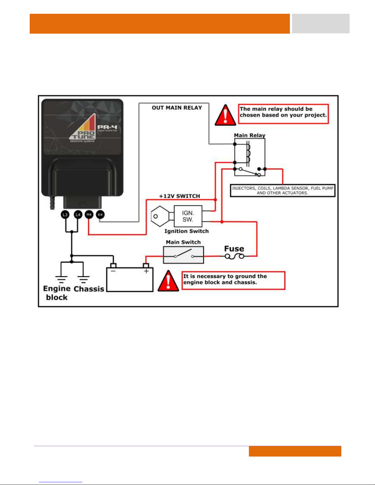
3. Installation Diagram
3.1 – Basic Wiring:
Special Case:
When the user wishes that an auxiliary output to remain triggered after switching off the engine (electric
water pump, electric fan, etc), the ECU (pin 87 of the relay) and the main relay power must be apart from each other
in separated switches.
Page 12
11
Document Revision: (2)
11
11
Product Manual
PR-4
4.1 –Inputs
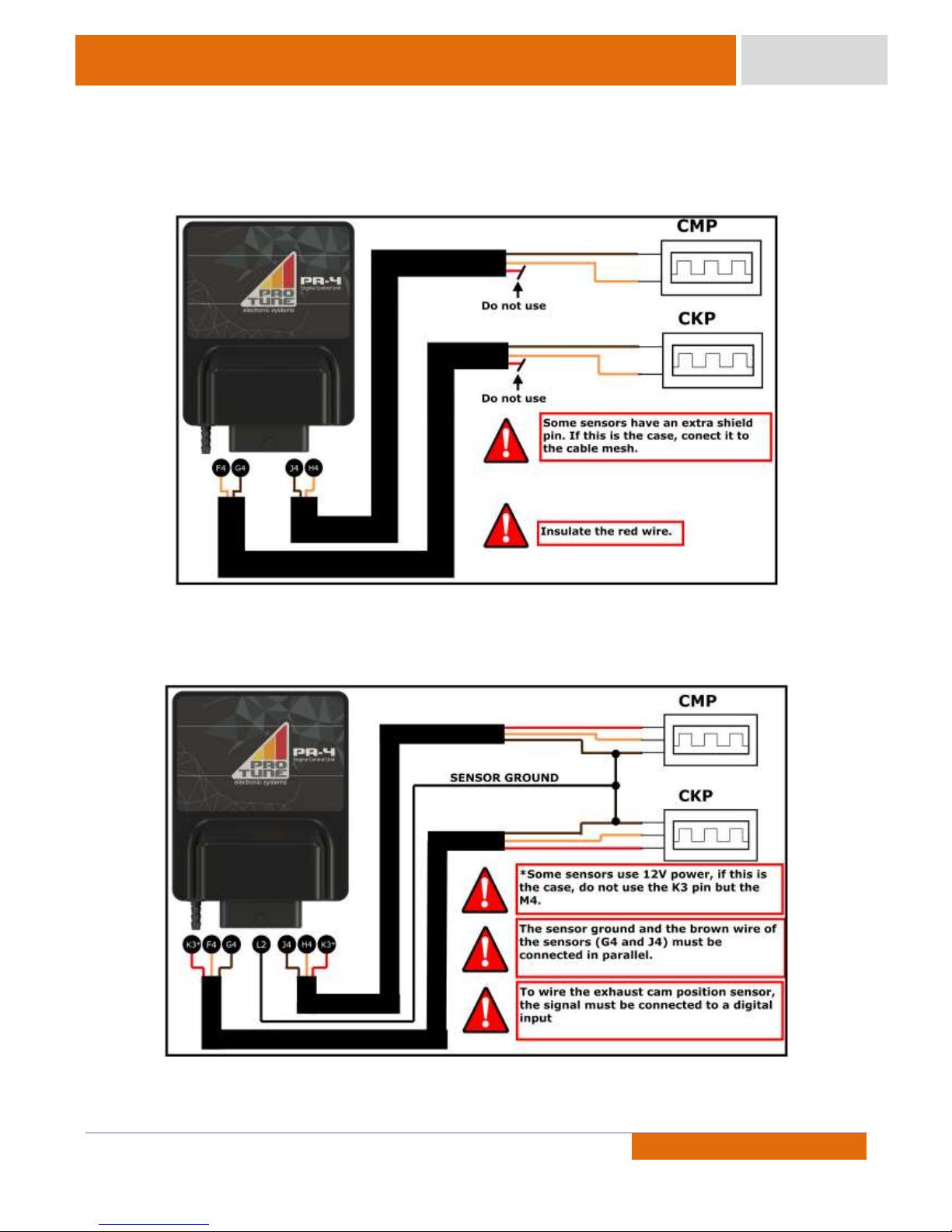
Crank and Camshaft Position Sensors
1 – Inductive type:
*PS: The mesh must be grounded either on the Power GND pin of the ECU or through the sensor. If the mesh is
not grounded or grounded in the both sides, sync problems may occur.
2 – Hall effect type:
Page 13
12
Document Revision: (2)
12
12
Product Manual
PR-4
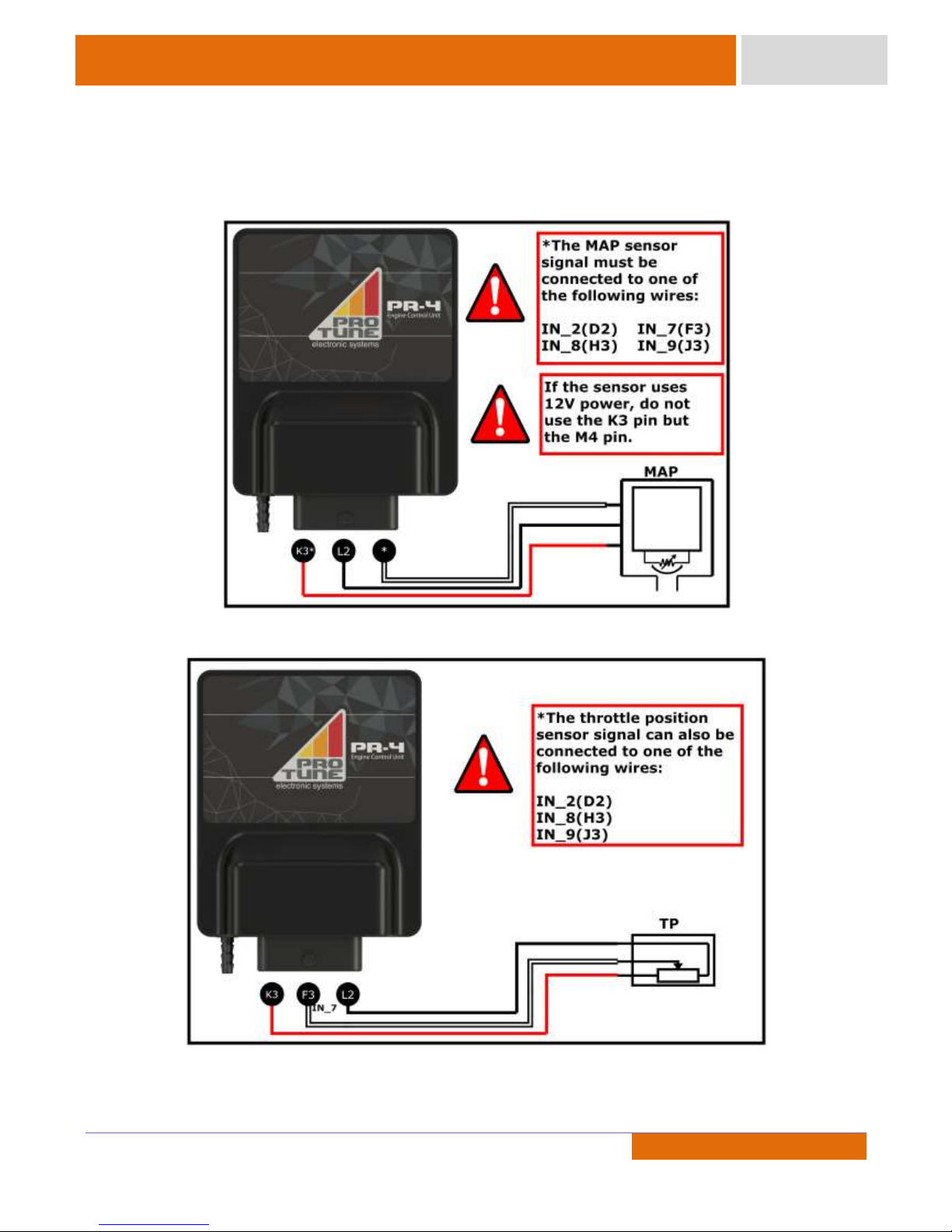
Manifold Absolute Pressure (MAP)
Pro Tune ECUs have an internal MAP sensor, all you have to do is install a hose connecting the intake
manifold to the ECU. External MAP sensors can be used as well by following the diagram below.
Throttle Position (TP)
Page 14
13
Document Revision: (2)
13
13
Product Manual
PR-4
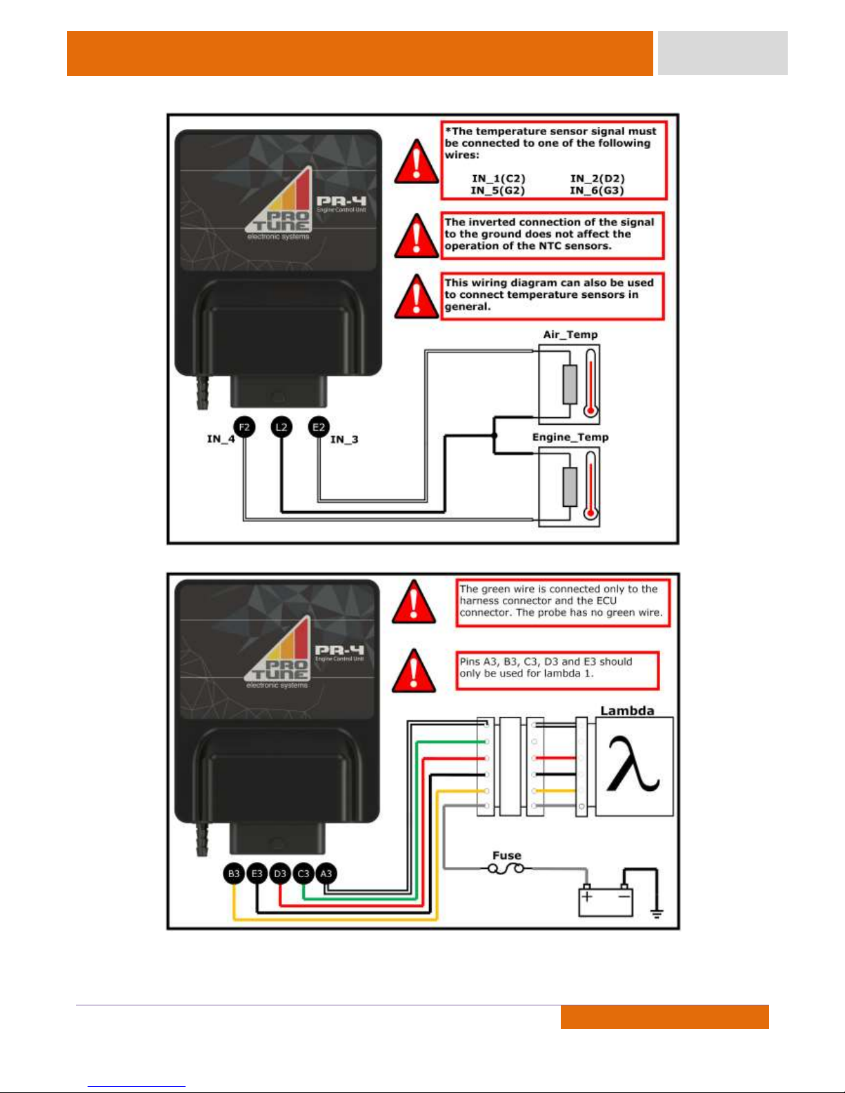
Engine and Intake Air Temperatures Sensors
Lambda Sensor LSU 4.2 / 4.9
CAUTION: LSU 4.2 and LSU 4.9 have different pinout. This scheme doesn’t illustrates sensor pinout.
Page 15
14
Document Revision: (2)
14
14
Product Manual
PR-4
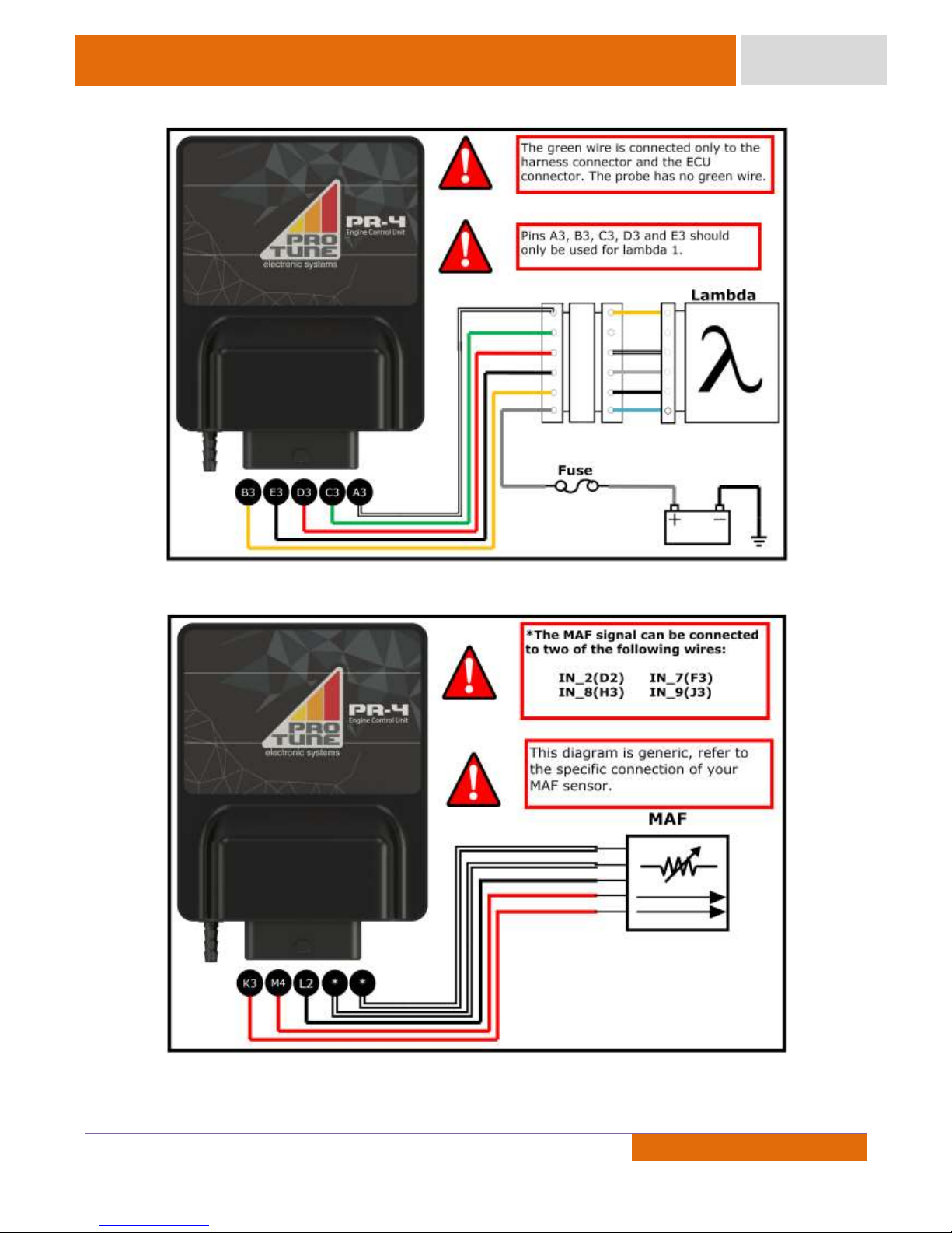
Lambda Sensor NTK UEGO
Mass Air Flow– MAF
Page 16
15
Document Revision: (2)
15
15
Product Manual
PR-4
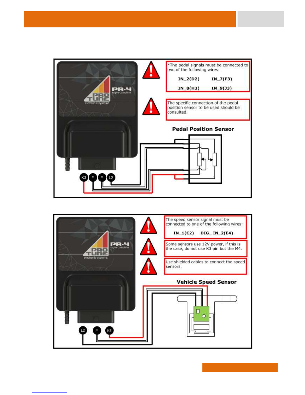
Pedal Position Sensor
Vehicle Speed Sensor
Page 17
16
Document Revision: (2)
16
16
Product Manual
PR-4
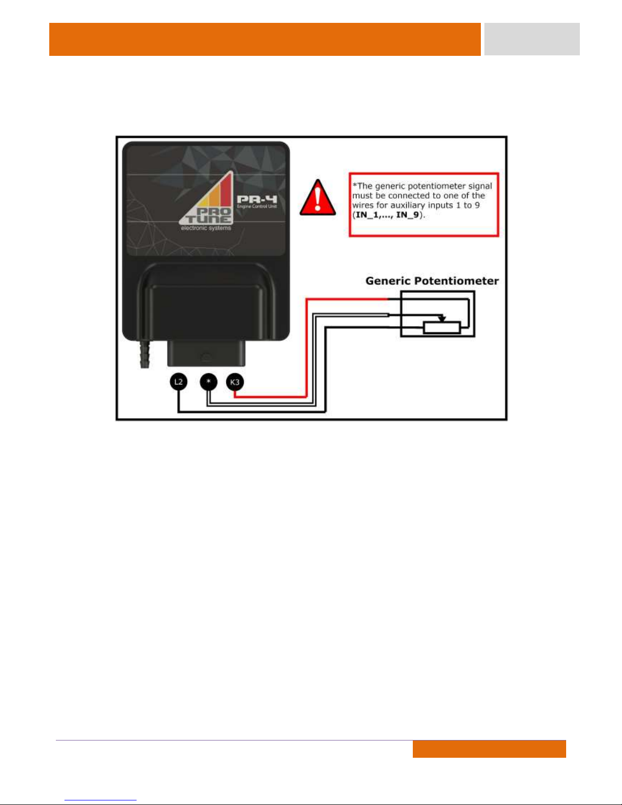
Generic Potentiometer (Gear Position, Steering Angle, etc)
Page 18
17
Document Revision: (2)
17
17
Product Manual
PR-4
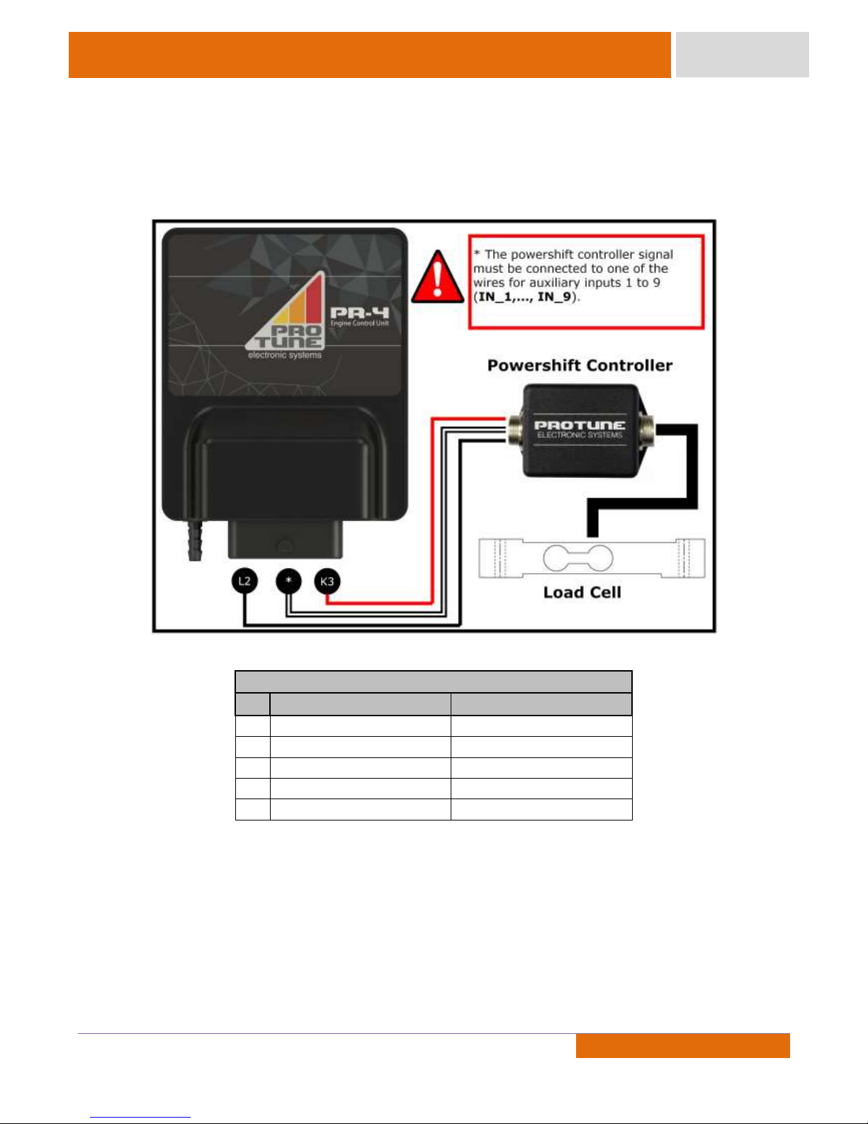
Load on Shift Lever
In order to use the Quick-Shift function, a load cell sensor must be applied to the vehicle shift lever. This
sensor is installed in Pro Tune’s factory, by sending the lever. For further information, contact technical support.
Alternatively, an activation signal switch can be used, the connection description is located on page 24.
Pinout
Pin
Function (4-way connector )
Function (5-way connector)
1
GND(-)
+ 12V
2
Sensor -
3 Sensor +
GND(-)
4
+ 5V
5
Signal (Vout)
Page 19
18
Document Revision: (2)
18
18
Product Manual
PR-4
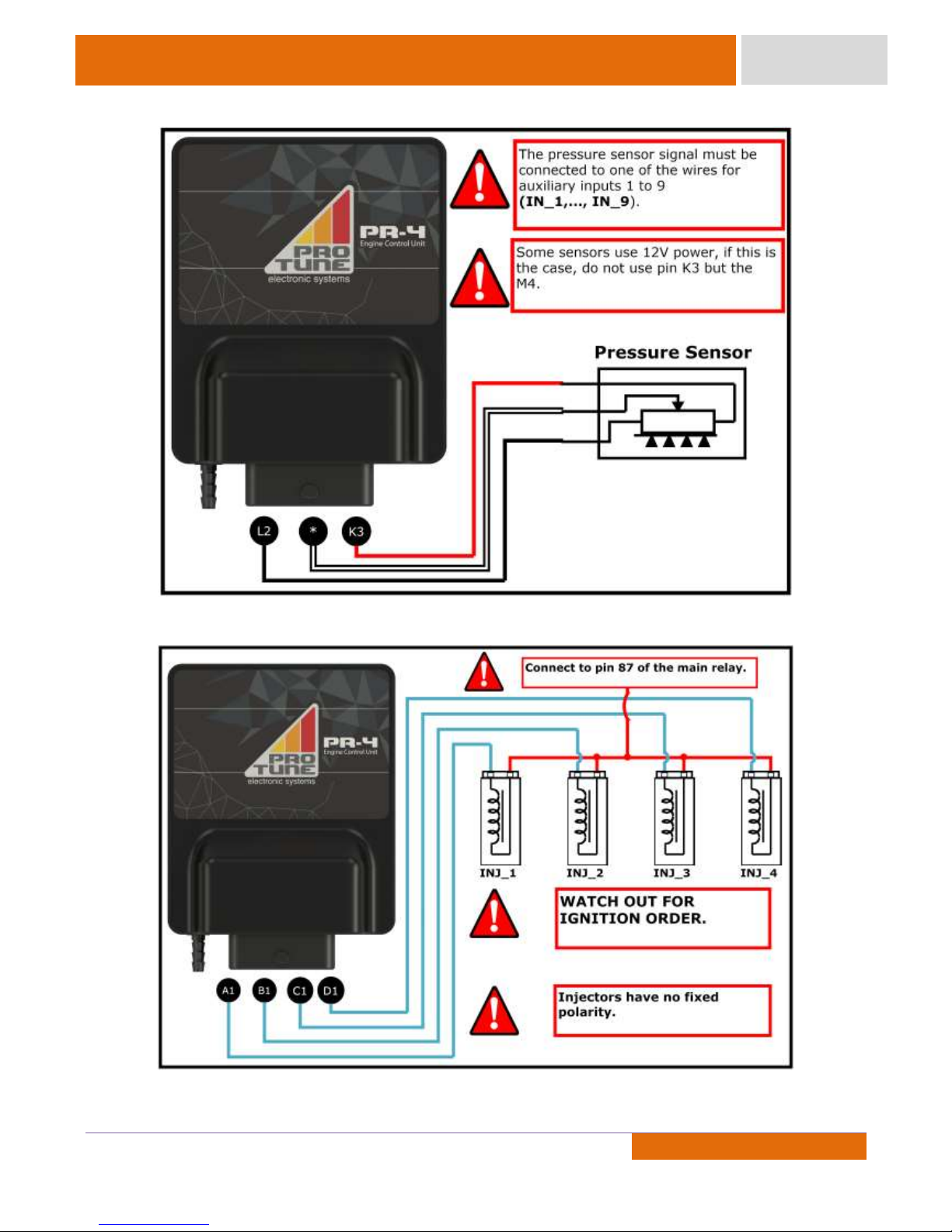
Oil / Fuel Pressure
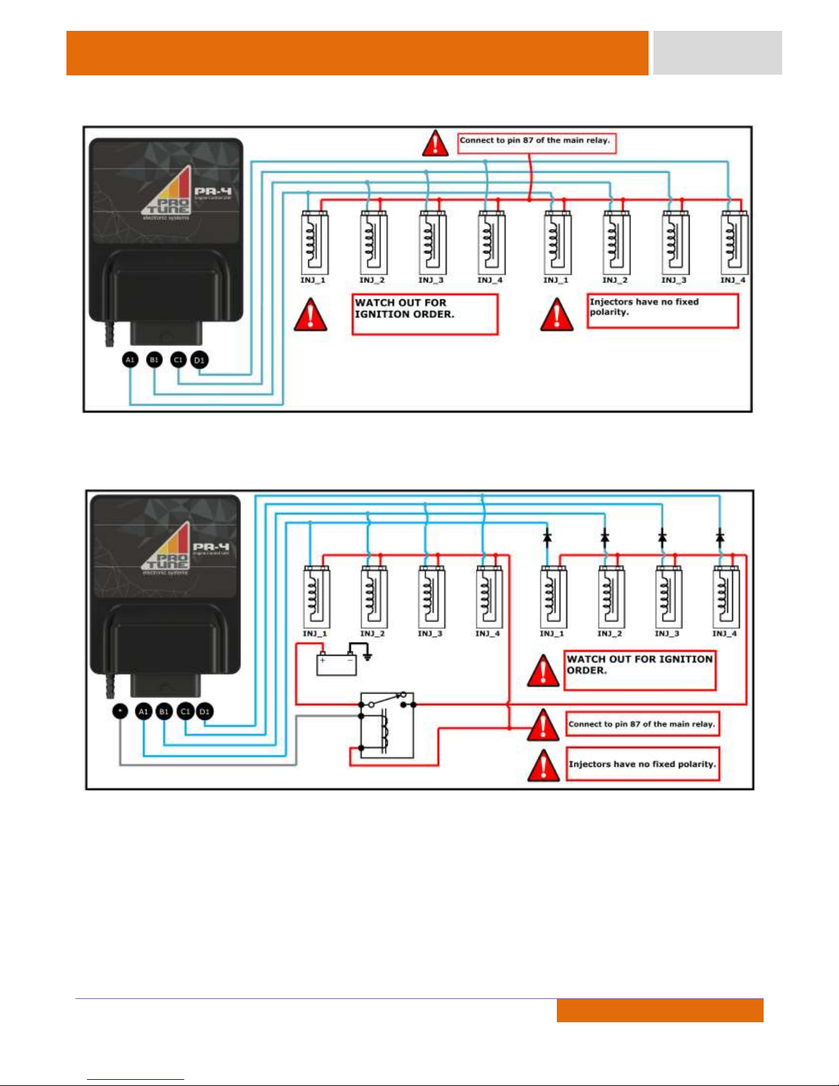
Injectors – Sequential
Ps: Up to two low impedance (Peak and Hold) injectors can be used per output with 2A/0,5A drive.
Page 20
19
Document Revision: (2)
19
19
Product Manual
PR-4
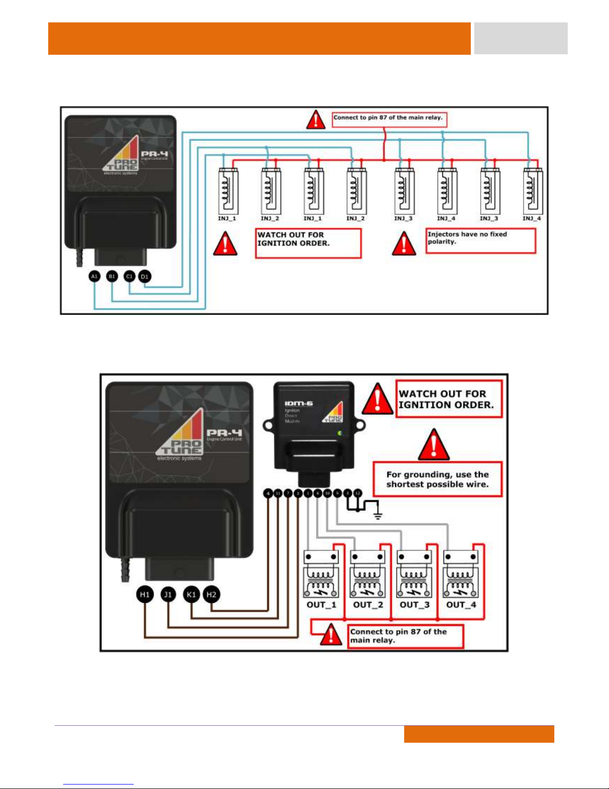
Injectors – 8 Cylinders Semi-Sequential
Injectors – Secondary Injector Rail
Page 21
20
Document Revision: (2)
20
20
Product Manual
PR-4
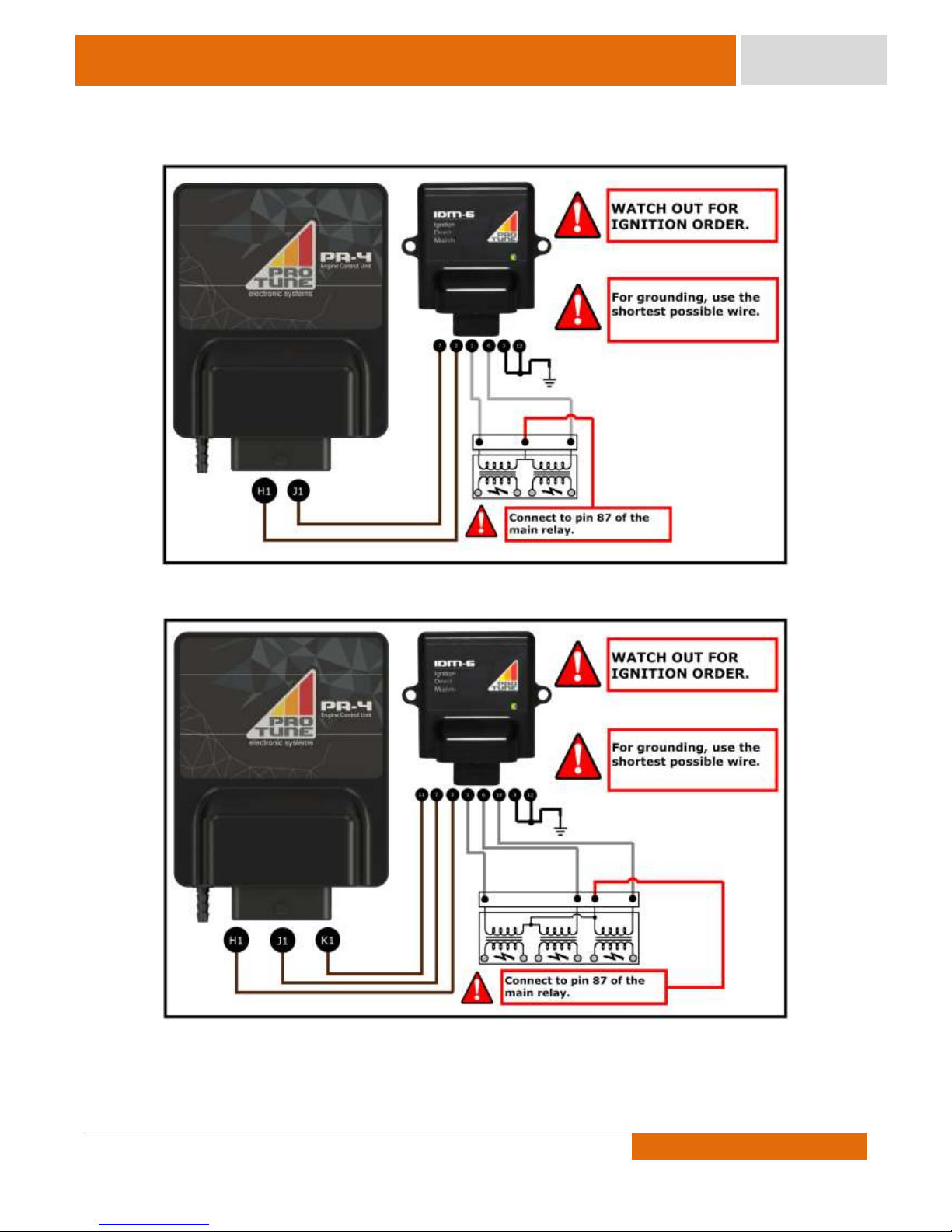
Injectors – Secondary Injector Rail Semi-Sequential
Ignition Coils without Integrated Driver
Except MSD coils and drivers
Page 22
21
Document Revision: (2)
21
21
Product Manual
PR-4
Dual Ignition Coils without Integrated Driver Semi-Sequential
Triple Ignition Coils without Integrated Driver Semi-Sequential
Page 23
22
Document Revision: (2)
22
22
Product Manual
PR-4
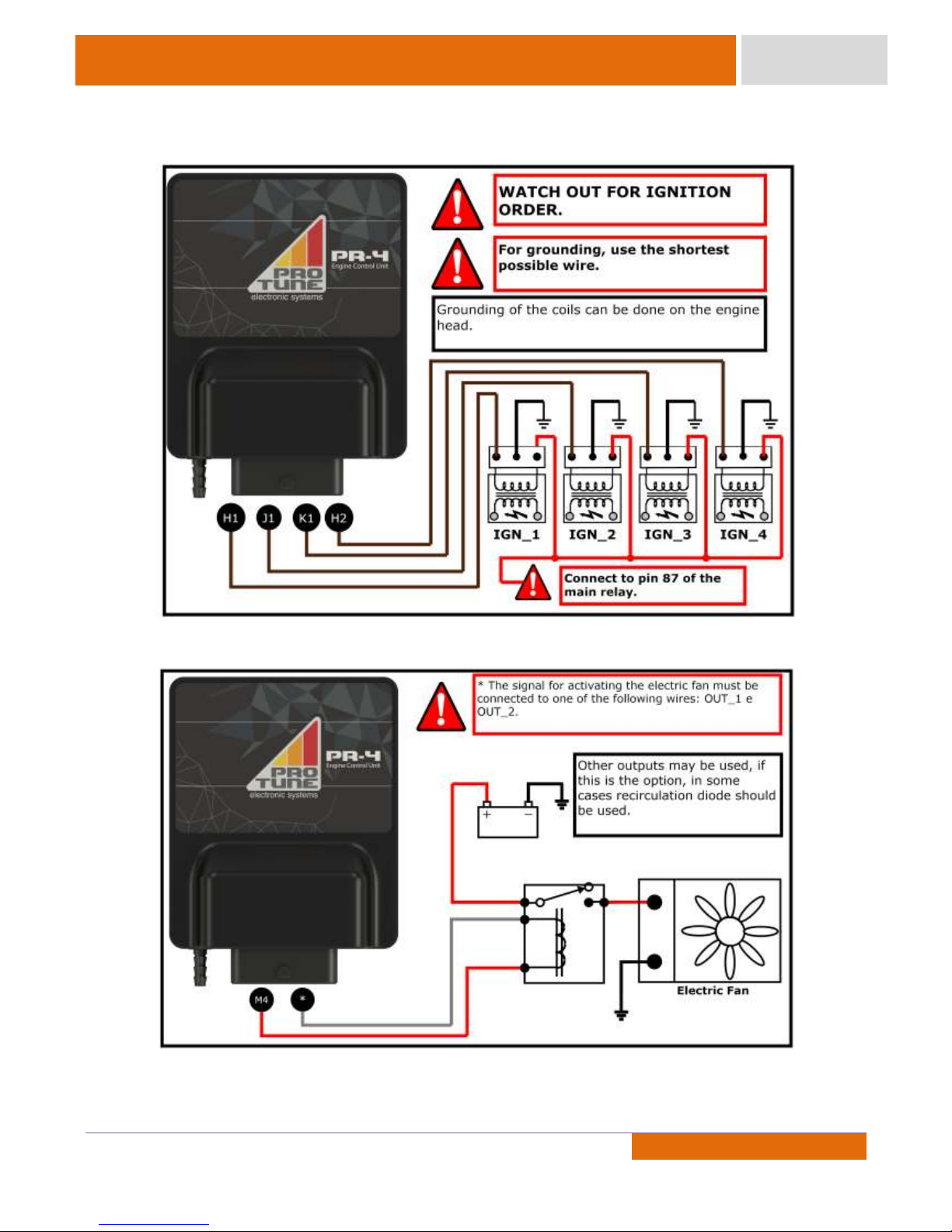
Ignition Coils with Integrated Driver
Electric Fan
Page 24
23
Document Revision: (2)
23
23
Product Manual
PR-4
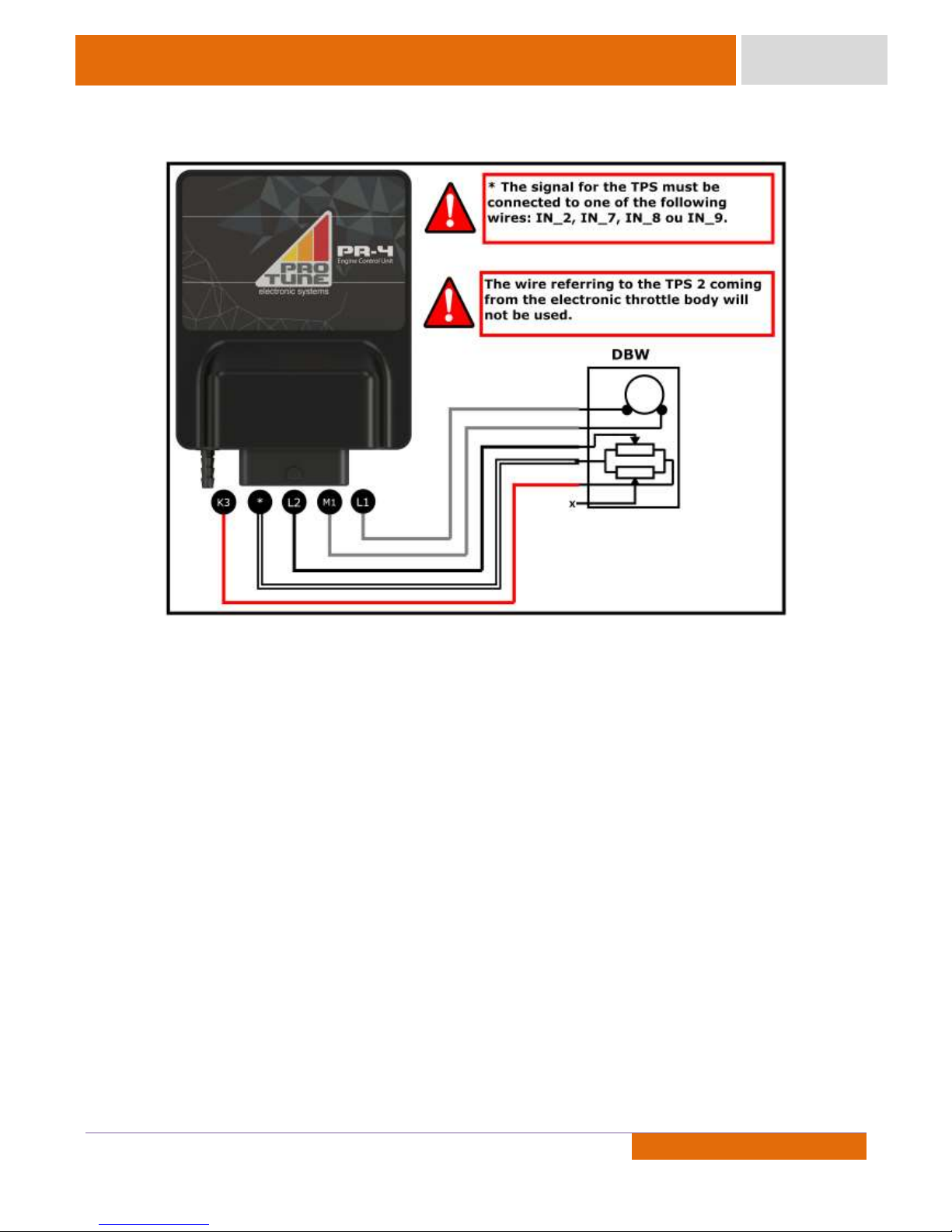
Electronic Throttle Control
NOTE:
The installation of an electronic throttle body requires some basic care to avoid damage to the user and
the device. Pro Tune recommends the following steps as a guide for installation.
1- Wire the sensor ground, 5 V sensor and TPS cables but KEEP OFF the motor wires (ETC + and ETC -).
2- Install the accelerator pedal.
3- Use Pro Tune Workbench to calibrate the pedal position and throttle position sensors. Then select the
ETC template that will be used.
4- Once the calibration is completed, connect the ETC motor cable (ETC+ and ETC-). Test to see if the
device is working properly.
If you wish to use a device model other than those listed in Pro Tune Workbench software, you must send
the device to Pro Tune.
Page 25
24
Document Revision: (2)
24
24
Product Manual
PR-4
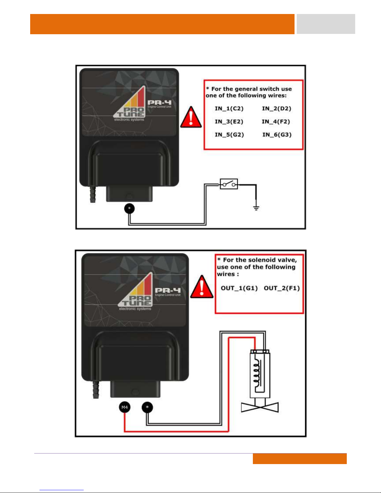
Switch
Solenoid Valve
Page 26
25
Document Revision: (2)
25
25
Product Manual
PR-4
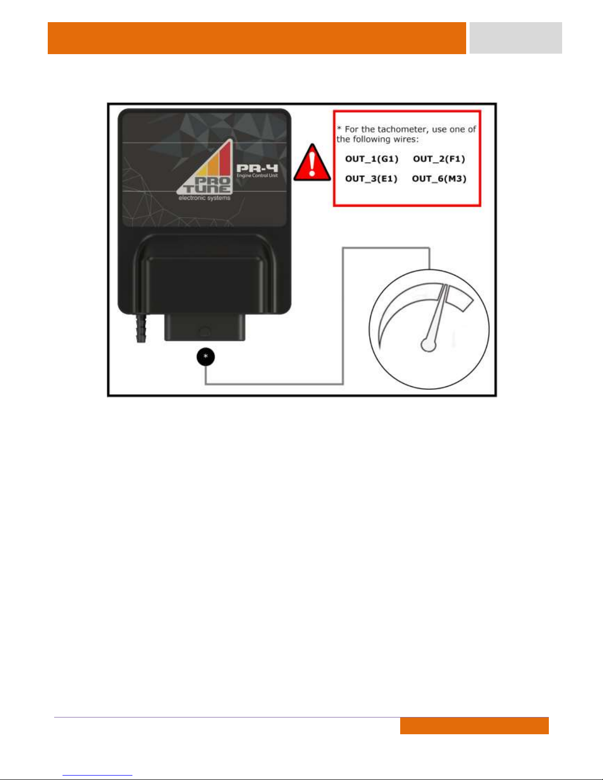
Tachometer Output
Page 27
26
Document Revision: (2)
26
26
Product Manual
PR-4
4. Sync
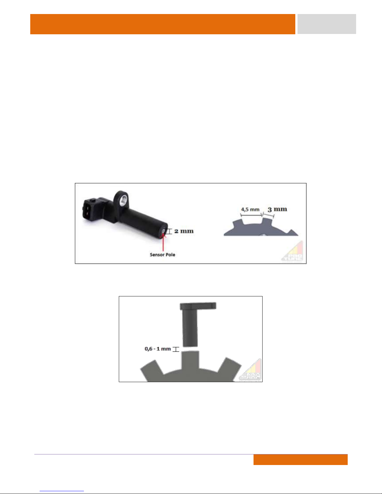
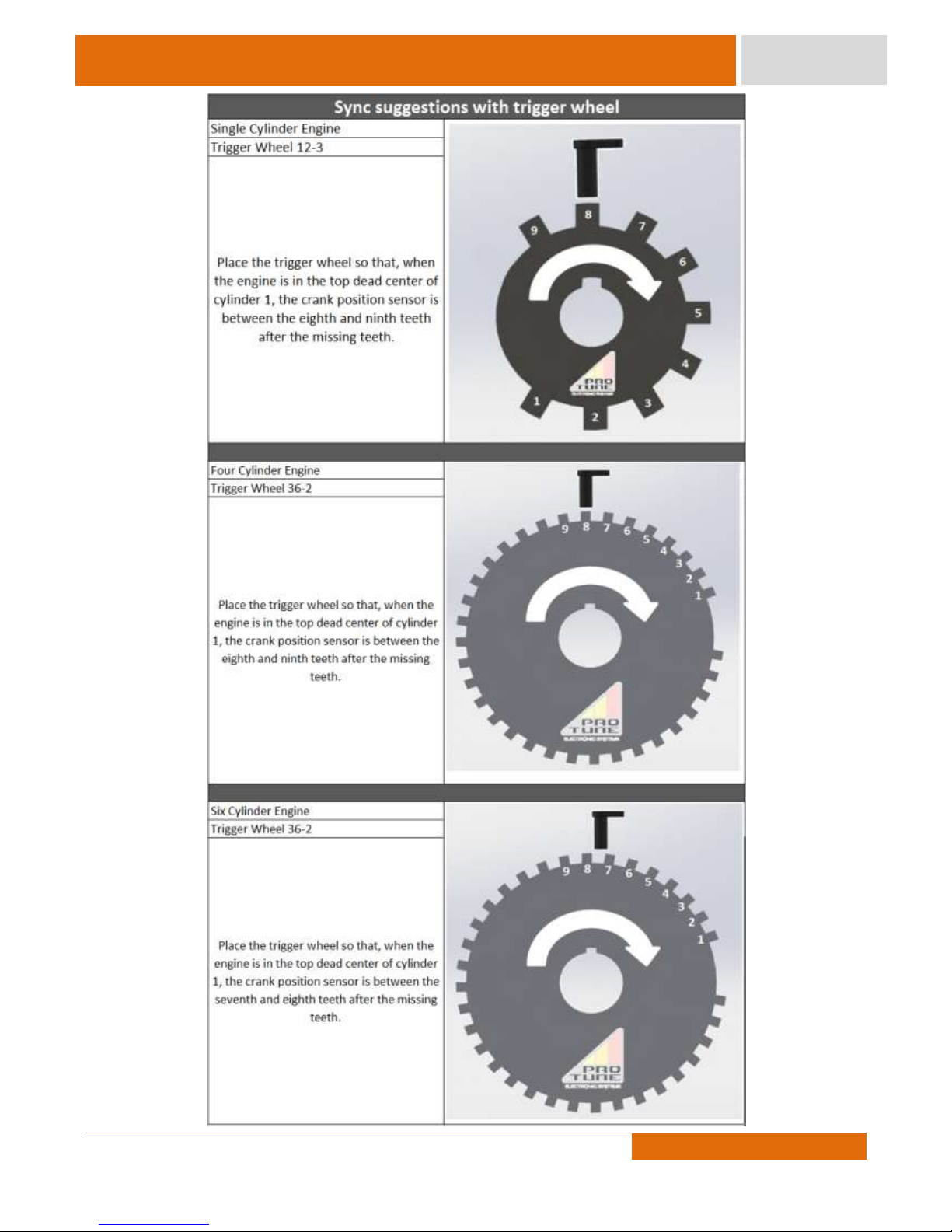
Trigger Wheel for Crank Position and Engine Speed:
Use a trigger wheel with a good finish quality, preferably the original engine trigger wheel.
Important comments:
Use a trigger wheel with teeth width at least one and a half times the width of the sensor pole, so as the
distance between the teeth, which should be symmetrical. The missing teeth width of the trigger wheel should be at
least one and a half times the size of the tooth, that is, 2.25 times the size of the pole of the sensor. Also note that
the distance between the sensor and the trigger wheel should be between 0.6 mm and 1 mm. In general, most of
sensors require a distance of 0.8 mm for the trigger wheel.
Example:
Page 28
27
Document Revision: (2)
27
27
Product Manual
PR-4
Page 29
28
Document Revision: (2)
28
28
Product Manual
PR-4
Distributor for Rotation and Phase Reading:
The distributor timing requires a distributor equipped with a Hall sensor. If the simultaneous or semisequential injection strategy is used, all of the distributor teeth can be the same size. For the sequential injection
strategy, it is necessary for the distributor to have one of the teeth smaller than the others in order to identify the
cylinder 1. If the distributor is symmetrical and the user wishes to use these strategies, it is possible to remove the
first half of the tooth referring to cylinder 1 , for identification of phase in this tooth.
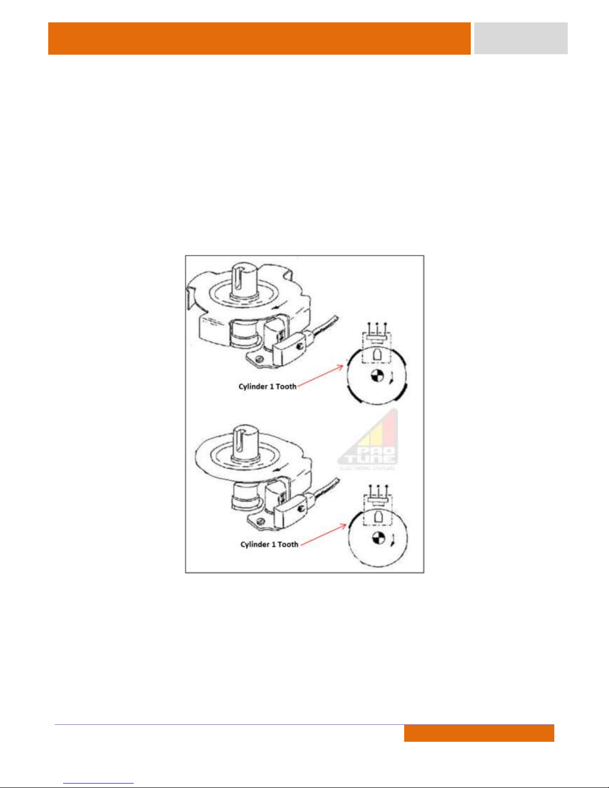
Distributor only for phase reading:
In this case, use a hall distributor with only one tooth. The teeth (or windows) of the distributor should be
removed, leaving only one (as shown below).
Camshaft Position Sensor for Phase Reading:
When using a phase sensor in the camshaft, make sure that the size of the tooth in the camshaft is
approximately one and a half times the width of the sensor pole.
Page 30

29
Document Revision: (2)
29
29
Product Manual
PR-4
Warranty / Support
Pro Tune products have a one year warranty (3 months legal warranty plus 9 months of special warranty
provided by Pro Tune) from the date of sale to the costumer. The warranty covers only manufacturing defects, and
any maintenance or repair will only occur at the Pro Tune factory. For the exchange or repair of any product under
warranty, it is necessary to present the invoice of the product purchase to one of Pro Tune's authorized resellers
with readable date.
Damage caused to products or other parts due to improper installation are not covered by the warranty.
Products with violation marks or mechanical shocks automatically lose their warranty. The warranty does not extend
to content or adjustments in the product memory.
If you have any questions regarding installation or operation, please contact our Technical Support team.
Pro Tune Technical Support
Comercial Phone: +55 (51) 3477 1653
Cell Phone: +55 (51) 9 8115 8314
E-mail: [email protected]
Pro Tune Electronic Systems
Brigadeiro Ivo Borges, 148
CEP: 92420-050
Canoas, RS, Brazil
Brazilian Industry
www.protuneelectronics.com.br
Page 31

30
Document Revision: (2)
30
30
Product Manual
PR-4
Pro Tune Electronic Systems
Brigadeiro Ivo Borges, 232 - 92420-050
Canoas, RS, Brazil
Brazilian Industry
www.protuneelectronics.com.br
 Loading...