

PRO TUNE MTD 2.4 Product Manual
PRODUCT MANUAL
PRO TUNE – MTD 2.4
MTD2.4

MTD2.4
DOC REVISION: 1
2
Disclaimer
Printed copies of this manual are not controlled.
This document is intellectual property of Pro Tune Electronic Systems. This manual
cannot be reproduced, distributed or transmitted by any means, electronic or printed, without
the proper authorization of Pro Tune Electronic Systems.
The company, its employees and resellers are not responsible for the incorrect use of
the information, inaccuracies or omissions in this document.
Pro Tune reserves the right to make changes to this document without prior notice.

MTD2.4
DOC REVISION: 1
3
Congratulations!
You just purchased a product from Pro Tune. We thank you for your trust in our
products, which are produced following stringent international standards together with highly
rigorous quality control, so that you receive a superior product in performance, finish and
functionality.
Our products are 100% made in Brazil, from the assembly of the electronic
components, through programming and finishing with the case machined in aluminum.
We hope you have a great experience with Pro Tune’s products. We are available to
answer any questions you may have and technical support in installing or operating any of our
products.

MTD2.4
DOC REVISION: 1
4
Summary
1. OVERVIEW 5
2. PACKAGE CONTENTS 6
3. RECOMMENDATION 7
4. INSTALLATION 8
4.1 Original Cars 8
4.2 Pro Tune ECUs 10
5. MAIN SCREEN 14
6. MAIN MENU 15
6.1 Settings 16
6.1.1 Configurable Channels 17
6.1.2 Brightness 18
6.2 Comms. Setup 19
6.3 Show Sensors 21
6.4 Alarms 22
6.5 Laps 24
6.6 Edit Screen 25
6.10 Shift Warning 26
TECHNICAL SPECIFICATIONS 27
ADAPTERS AND CONNECTORS 28

MTD2.4
DOC REVISION: 1
5
1. OVERVIEW
Mini Dash 2.4 is equipment for monitoring data. It has functions such as data exhibition,
alarms and shift light. In addition, it has resistive touch screen and GPS.
• High brightness LCD touch screen.
• Integrated GPS.
• Two analog inputs for sensors.
• Communication protocols: OBDII / CAN / ISO.
• Lap Timer function with automatic recognition by GPS.
• Presentation in 3 languages: Portuguese / English / Spanish.
• Metric and imperial units systems.
• 10 configurable channels.
• Configuration of up to 6 alarms in 2D.
• Communication in OEM vehicles by OBDII port.
• Communication with Pro Tune ECUs.

MTD2.4
DOC REVISION: 1
6
2. PACKAGE CONTENTS
The following items are present in the packaging:
- Mini Dash 2.4;
- Universal adapter for connection to other Pro Tune and OBD-II products;
- GPS antenna;
- Instruction manual and Pro Tune software contained in the Pen drive;

MTD2.4
DOC REVISION: 1
7
3. RECOMMENDATION
- Ensure that the product is securely attached, preventing the MTD2.4 from falling during
vehicle movement.
ATTENTION: Attachment failure may cause accidents.
- The MTD must be installed in a region of the vehicle where it is protected from
scratches and shocks;
- Do not handle or transport the MTD through its power cable;
- Never pierce the case;
- The magnet on the base of the GPS wire antenna must be installed in a grounded
metallic point of the vehicle. The receiving base should be facing upwards.
- The GPS wire must be installed on the outside of the vehicle to ensure perfect
synchronization with the satellites.
- Synchronizing satellites signals may take some time, especially if it is the first time the
MTD has been turned on in a new location.
- The wire cable should be secured and not in contact with any sharp surface;
- Do not paint the GPS antenna with (metallic) paint, as this causes interference and
consequent malfunction of the product;
MTD2.4
DOC REVISION: 1
8
4. INSTALLATION
4.1 Original Cars
To install the MTD 2.4 in original cars, you must use the adapter with the OBDII
connector.
1) The MTD must be securely attached to the vehicle.
2) The standard 8-way female MTD connector must be connected to the male 8 way
connector of the adapter.
3) The OBDII connector must be connected to the OBDII port of the vehicle (see vehicle
manual).
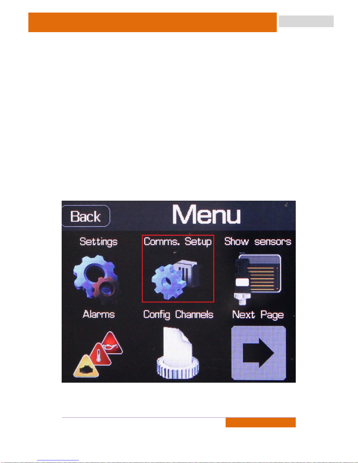
4) The user must access the MTD main menu and then select the "Comms" icon to
change the communication mode to OBDII CAN.
Access icon for Communications menu.
MTD2.4
DOC REVISION: 1
9
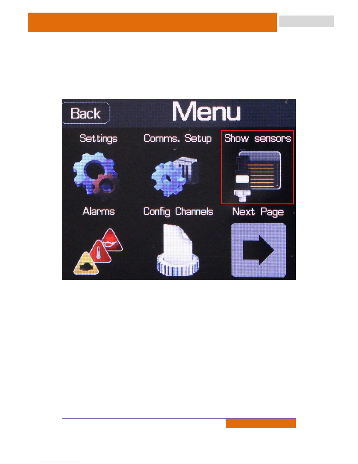
5) Check if there is communication by accessing the "Show Sensors" option in the main
menu, if information is displayed in the RPM channel the installation is complete, just press the
back button until the configuration is saved.
Icon to show sensors
6) If the sensor information is not displayed, return to the Comms Menu and change the
communication type to OBDII ISO.
7) Access the "Show Sensors" option in the main menu and check for communication.
ISO communication can take up to 5 minutes to be established.
NOTE: In some vehicle models, it may be necessary to use the Universal OBDII cable for
communication. This cable is purchased separately.
MTD2.4
DOC REVISION: 1
10
4.2 Pro Tune ECUs
To install MTD in vehicles using Pro Tune ECUs the Pro Tune CAN adapter is used without
the OBDII connector.
1) The MTD must be securely attached to the vehicle.
2) The standard 8-way female TDL connector must be connected to the male 8 way
connector of the adapter.
3) The female 5-way connector of the adapter must be connected to the 5-way male
connector of the ECU wiring harness.
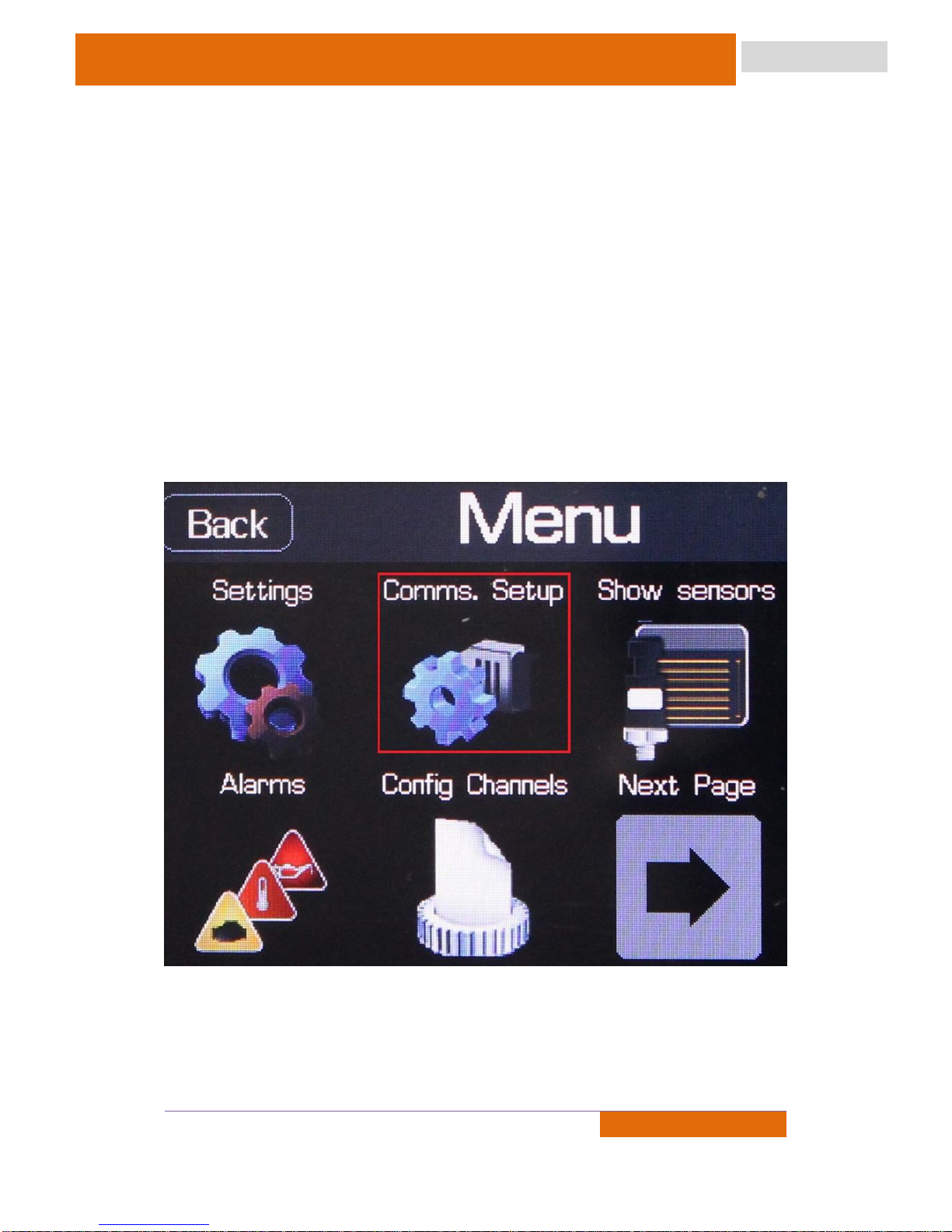
4) The user must access the MTD main menu and then select the "Comms" icon to
change the communication mode to Pro Tune CAN. In this same menu you need to set the
communication speed to 500 kbps.
Access icon for Communications menu.

MTD2.4
DOC REVISION: 1
11
5) Check for communication by accessing the "Display Sensors" option in the main
menu, if information is displayed on the RPM channel the installation is complete, just press the
back button until the configuration is saved.
6) If the sensor information is not displayed, connect the ECU to the computer using the
USB cable, open the Pro Tune Workbench software and configure the CAN BUS communication,
500 kbps, in the External Communication menu. In addition, you should change the Dash
protocol to "Pro Tune Multiple Devices" and the refresh rate to 20 Hz.
 Loading...