

Page 1
Ver 1710 Rev 1
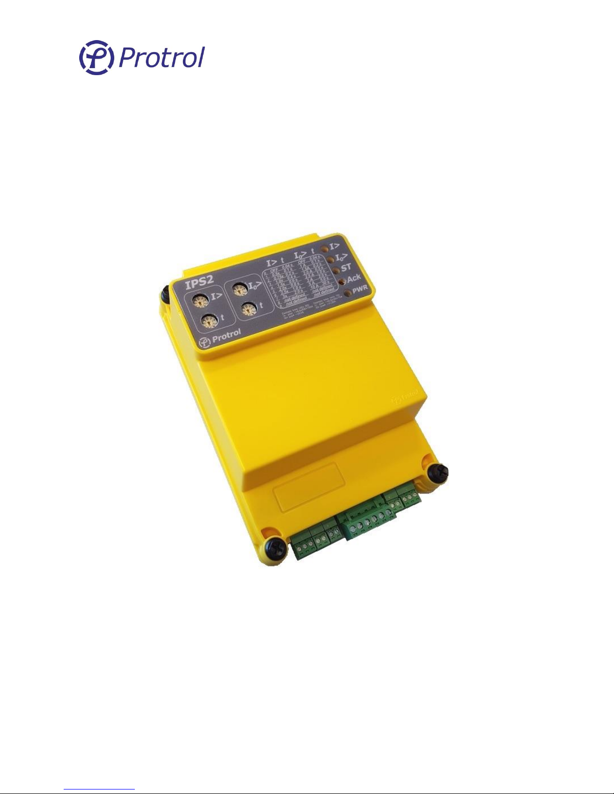
IPS2 24 VDC
Fault Detector
IPS2 24 VDC is a fault detector for overcurrent and directional earth
faults that indicates faults using its relay outputs and IEC 60870-5-
101.
Since the algorithm for earth fault detection does not require a
voltage transformer, IPS2 gives a very cost-efficient fault detection
with high sensitivity for pass through faults in impedance earthed
networks.
Page 2

Ver 1710 Rev 1
M A N U A L
1 Contents
1 Contents ___________________________________________________________________ 2
2 Schematic Overview __________________________________________________________ 3
3 Safety Information ___________________________________________________________ 4
4 Functional Description ________________________________________________________ 5
4.1 Detector Function _______________________________________________________________ 5
4.2 Remote Terminal Unit Function ____________________________________________________ 7
4.3 System and service interfaces ______________________________________________________ 8
5 Hardware __________________________________________________________________ 9
5.1 IPS2 24 VDC Main Printed Circuit Board Rev. C ________________________________________ 9
5.2 IPS2 24 VDC Top Printed Circuit Board ______________________________________________ 11
5.3 Protrol Tool for IPS2 ____________________________________________________________ 13
5.4 Setting the IPS2 to Service Interface Mode __________________________________________ 13
5.5 Communication Cable ___________________________________________________________ 13
5.6 Protrol Main Window ___________________________________________________________ 14
5.7 IPS2 Transient Fault Recorder _____________________________________________________ 16
6 Configuration of IPS2 24 VDC __________________________________________________ 18
6.1 Creating or Adjusting a Configuration File ___________________________________________ 18
6.2 Download a Configuration File to the IPS2 Device _____________________________________ 21
7 Testing and Commissioning of IPS2 _____________________________________________ 23
7.1 Binary I/O_____________________________________________________________________ 23
7.2 Current Injection Test ___________________________________________________________ 23
7.3 EF Trig Level Check _____________________________________________________________ 24
7.4 Test of IPS after Commissioning ___________________________________________________ 24
7.5 Offset Elimination (zero offset calibration) __________________________________________ 24
Page 3
Ver 1710 Rev 1
Protrol AB Tel: 031- 45 82 00
Ullevigatan 19 internet: www.protrol.se
411 40 Göteborg 3 e-mail: [email protected]
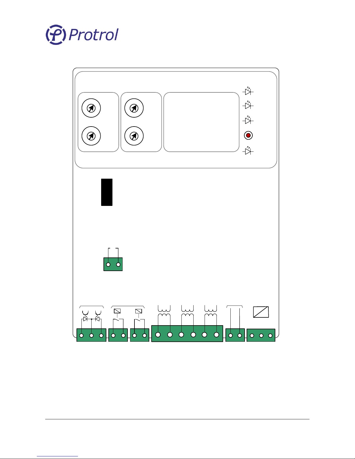
2 Schematic Overview
RS232
Fault indication
Internal
port
5
0
1
2
3
4
6
7
8
9
5
0
1
2
3
4
6
7
8
9
PWR
ST
I>
I0>
IPS2
0 OFF 0.04 s
1 0.5x 0.1 s
2 0.75x 0.2 s
3 1.0x 0.4 s
4 1.5x 0.6 s
5 2.0x 0.8 s
6 2.5x 1.0 s
7 3.0x 2.0 s
OFF 0.04 s
1.0 A 0.1 s
1.5 A 0.2 s
2.0 A 0.5 s
2.5 A 1.0 s
3.0 A 2.0 s
5.0 A 5.0 s
10 A 30 s
I>
I0> tI> t
X2 X3 X4 X6
X5
X1
Binary
inputs
1
2
3
C
21 21
I
A
1A
C
2
I
B
1A
C
4
I
C
1AC
6
3
5
1
2
RS485
RX/TX
1
24-48 VDC
+
GND
_
_
2 3
-
1
+
-
Ack
t
5
0
1
2
3
4
6
7
8
9
5
0
1
2
3
4
6
7
8
9
I0>
t
21
X7
EXT
LED
Figure 1. IPS2 24 VDC overview.
Page 4

Ver 1710 Rev 1
Protrol AB Tel: 031- 45 82 00
Ullevigatan 19 internet: www.protrol.se
411 40 Göteborg 4 e-mail: [email protected]
3 Safety Information
The device should be connected to a ground terminal.
If the cover is removed, avoid contact with the main circuit board and terminals. The unit is
powered by 24 VDC but the wires to binary inputs and outputs are designed for higher signal
voltages.
If the unit is disconnected and the cover is removed, make sure that proper precautions are made
to protect the unit from electrostatic discharges.
When connecting and disconnecting the current terminals always short-circuit the current path to
avoid open circuits!
Short circuiting the current terminals when the earth fault detector is enabled is likely to be
interpreted as an apparent earth fault. If the EF detector has no binary input qualification enabled
the IPS2 unit should either be switched off or pluggable connectors in X2-X3 should be
disconnected.
Hint: This “feature” can be used for example in a test situation when the whole chain from IPS2 to
the SCADA system should be verified. When the IPS2 unit is in operation and there is a normal load
current it is usually possible to activate the earth fault detector by short-circuiting one phase on the
terminal screws with a short cable.
Page 5

Ver 1710 Rev 1
Protrol AB Tel: 031- 45 82 00
Ullevigatan 19 internet: www.protrol.se
411 40 Göteborg 5 e-mail: [email protected]
4 Functional Description
4.1 Detector Function
True Fault Pass Through Earth Fault Detection
Protrol’s patented Fault Pass Through earth fault detection is suitable for all indirectly earthed networks. It
is capable of detecting high impedance and arcing earth faults. It analyses the transient nature of phase and
neutral currents and points reliably out the fault direction with respect to the measurement point. Note
that no voltage measurement is necessary for good selectivity at very low currents. The sensitivity is
comparable with that of a directional earth fault protective relay.
At an earth fault the detector will set itself into Trig state and evaluate if the fault is upstream or
downstream the unit. If the fault is downstream, it will switch to Start state. In this mode, the detector
evaluates the I0 residual current until the Operation Delay has passed. If the residual is high after the set
time, the detector will enter Trip state.
Note that both a Start and a Trip indication means that an earth fault has occurred downstream the
detector. A Start without a subsequent Trip indication means that either the fault current is too low, or the
fault was of transient type and was gone after the Operation Delay time. Thus, the Start object, available
remotely, can be used as an early indication of an incipient fault.
Some periods after the disturbance has vanished, the detector returns to its normal state.
High I0 Detection
The IPS2 supervision alarm for high residual current if the steady-state I0 current exceeds 16 times the I0
pickup level, as specified by the rotary switch on the front panel1.
The main purpose of this alarm is to indicate that something is wrongly connected, either wrong polarity or
missing phase.
An alarm is indicated by flashing the I0> LED, also see the Section 5.2 IPS2 24 VDC Top Printed Circuit
Board.
Overcurrent Detection
The IPS2 unit has one overcurrent stage that can be configured using the rotary switch at the front panel.
Phase Break Detection
The phase break detection alarm is activated - if one phase is “dead” while the other two are “alive”, a
phase break is signaled locally and on the system interface. A phase is considered “dead” if the current is
lower than the I0 pickup level, and “alive” if the current is higher than 4 x the I0 pickup level.2
An alarm is indicated by flashing the I> LED, also see the Section 5.2 IPS2 24 VDC Top Printed Circuit
Board.
1
If the earth fault stage is deactivated, the High I0 steady-state limit is set to 160 A.
2
If the earth fault stage is deactivated, the “dead” threshold is set to 5 A while “alive” is 20 A.
Page 6

Ver 1710 Rev 1
Protrol AB Tel: 031- 45 82 00
Ullevigatan 19 internet: www.protrol.se
411 40 Göteborg 6 e-mail: [email protected]
Output relays
The output power relays in the IPS detector enable direct operation of switching devices. Thus, it is possible
to disconnect faults before the protection in the distribution substation reacts, minimizing the
consequences for the users upstream the fault.
Fault acknowledgement
The LEDs including the external LED can be reset either by pressing the Ack-button or automatically when
the time of the Protrol Tool parameter LED flashing time has elapsed.
Page 7
Ver 1710 Rev 1
Protrol AB Tel: 031- 45 82 00
Ullevigatan 19 internet: www.protrol.se
411 40 Göteborg 7 e-mail: [email protected]
4.2 Remote Terminal Unit Function
The IPS2 unit includes a Remote Terminal Unite (RTU) function that can be employed to share Start and
Trip information as well as other binary and analogue objects.
Binary objects
There are nine objects for internal signals and the two binary inputs of the IPS2 unit that can be transmitted
on the RS485 System Interface (Single Point) using the IEC 60870-5-101 protocol.
▪ I
0
> Start
▪ I
0
> Trip
▪ I> Start
▪ I> Trip
▪ I
0
> Arcing
▪ Phase break
▪ Binary Input 1
▪ Binary Input 2
▪ High residual current
Analogue objects
Five analogue objects, three phase currents, residual current and fault detected phase, can be transmitted
for supervision/ information purposes. See the Table 1 Explanation of the Protrol IPS2 24 VDC Configuration
settings for more information.
Protocol
The available protocol is:
▪ IEC 60870-5-101
Supported selection of ASDUs:
Standard range
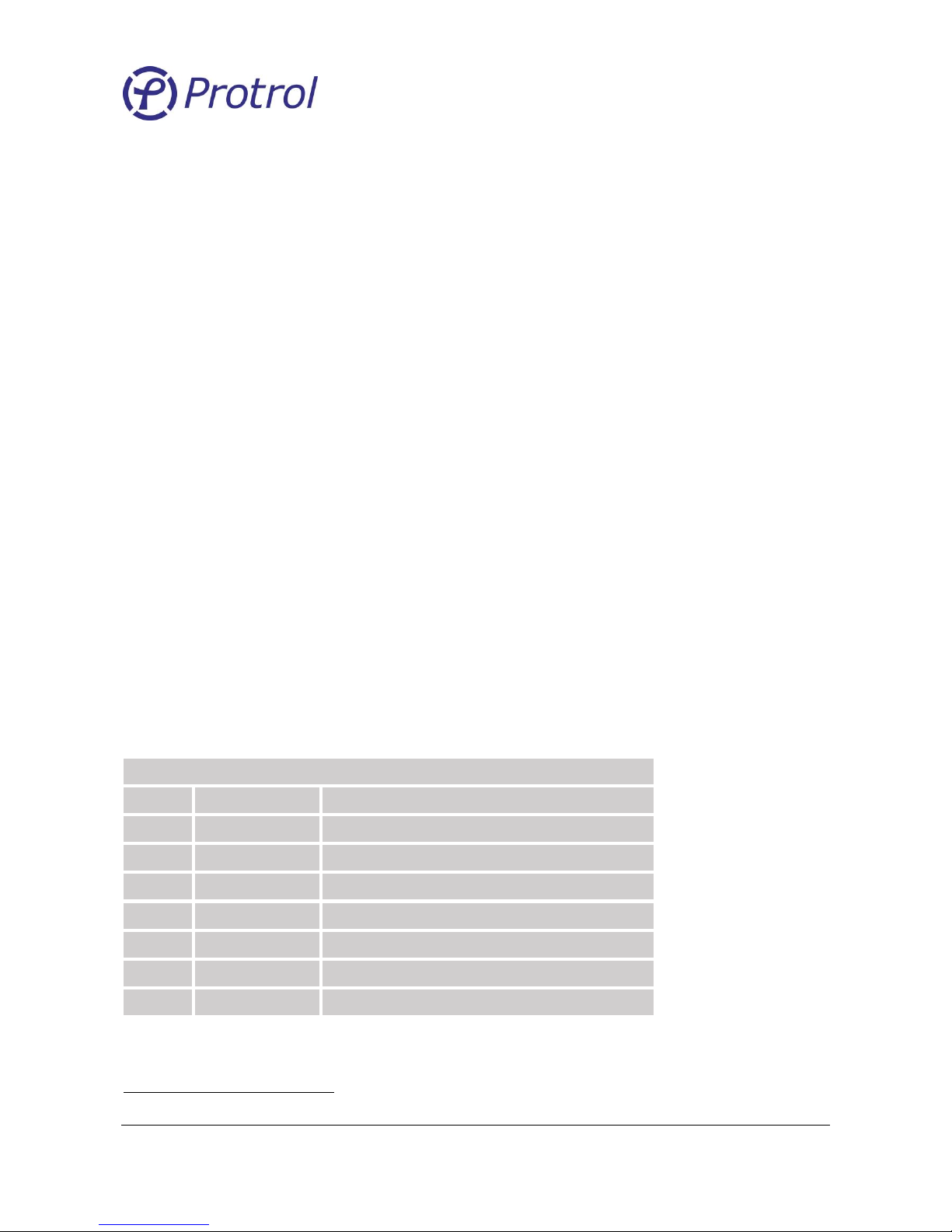
No
Type ID
Description
<1>
M_SP_NA_1
Single-point information
<2>
M_SP_TA_1
Single-point information with time tag
<9>
M_ME_NA_1
Measured value, normalized value
<11>
M_ME_NB_1
Measured value, scaled value
<13>
M_ME_NC_13
Measured value, short floating point number
<100>
C_IC_NA_1
Interrogation command
<103>
C_CS_NA_1
Clock synchronization command
3
M_ME_NC_1 R32-IEEE STD 754
Page 8

Ver 1710 Rev 1
Protrol AB Tel: 031- 45 82 00
Ullevigatan 19 internet: www.protrol.se
411 40 Göteborg 8 e-mail: [email protected]
4.3 System and service interfaces
The IPS2 unit has a system interface for RTU communication and a service interface for handling of
transient fault recorder data.
A hardware and a protocol configuration must be made to switch between the two different interfaces.
Hardware configuration is made with a jumper on a 3-pole header, see the coming chapter “IPS2 24 VDC
Main Printed Circuit Board Rev. ” for details.
The device protocol is switched by pressing and holding the ACK button until the changed mode is indicated
by a short flash on the I> or I0> LED.
System interface
The physical port for the system interface is the RS485 port (X5), see the chapter “Schematic Overview” for
connector placement.
The jumper in the 3-pole header must be placed in position 2 – 3 for RS485 communication.
The device protocol is switched by pressing and holding the ACK button until the changed mode is indicated
by a short flash on the I0> LED.
The device is always initiated, after a power down or reset, with the system interface protocol activated.
Service interface
The physical port for the service interface is the internal RS232 port, see chapter “IPS2 24 VDC Main Printed
Circuit Board Rev. ” for details.
The jumper in the 3-pole header must be placed in position 1 – 2 for RS232 communication.
The device protocol is switched by pressing and holding the ACK button until the changed mode is indicated
by a short flash on the I> LED.
Please observe that the IPS2 is always initiated, after a power down or reset, with the system interface
protocol activated.
Page 9
Ver 1710 Rev 1
Protrol AB Tel: 031- 45 82 00
Ullevigatan 19 internet: www.protrol.se
411 40 Göteborg 9 e-mail: [email protected]
5 Hardware
The IPS2 unit is composed of two printed circuit boards (PCBs); one large circuit board forming the base and
a top circuit board that is located above of the other just beneath the front panel.
To access the reset button, firmware download port (C2 interface) and the internal serial port of IPS2, the
front cover must be removed. This is easily accomplished by removing the four screws in the corners of the
cover. Note that the screws need only to be turned 90 degrees.
5.1 IPS2 24 VDC Main Printed Circuit Board Rev. C
Pluggable Terminal Blocks
External cables are attached to the lower side of the IPS2 using pluggable contacts. For more information
about each conductor in the contacts, please refer to the Schematic Overview in Figure 1.
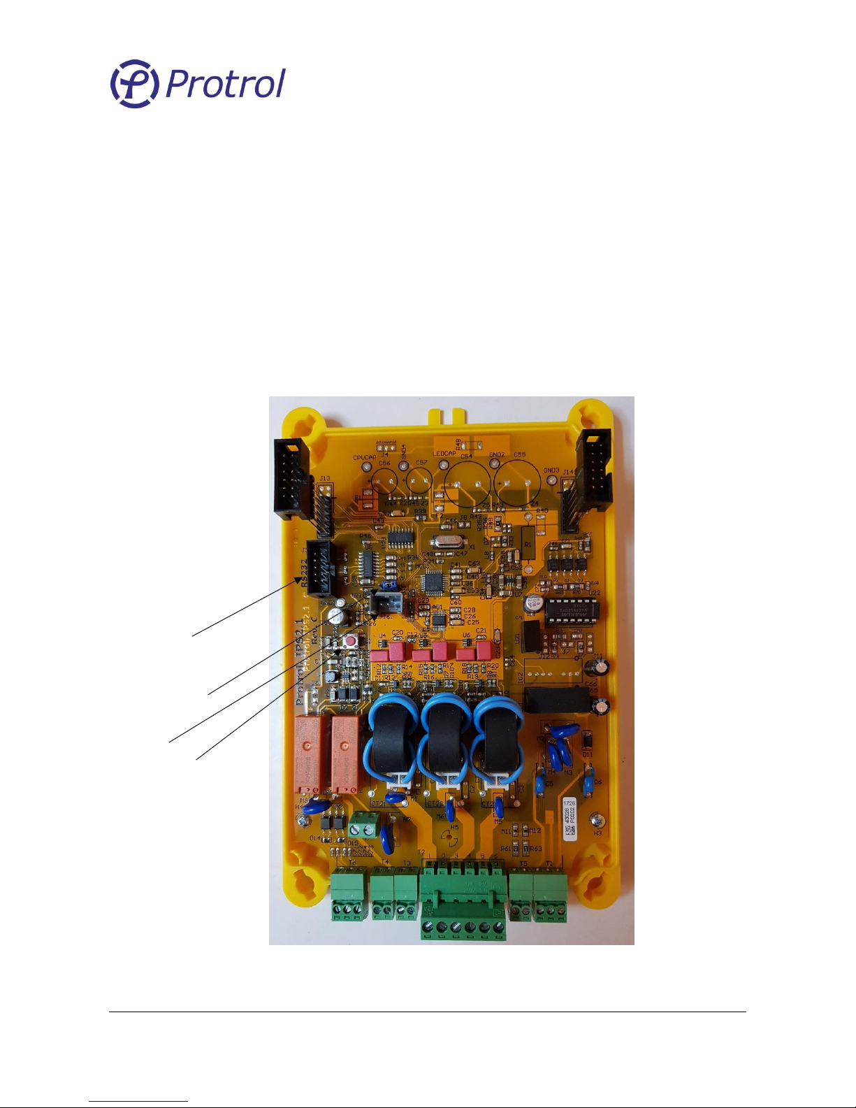
Figure 2. IPS 24 VDC Main PCB Rev C.
Service Port
C2 Port
Reset switch
3-pole header
Page 10

Ver 1710 Rev 1
Protrol AB Tel: 031- 45 82 00
Ullevigatan 19 internet: www.protrol.se
411 40 Göteborg 10 e-mail: [email protected]
Reset button
Pressing the orange button results in a reset of the unit. All recordings from previous faults and events are
lost. Configuration settings are kept during reset.
Service Port
The service port connector is found on the upper side of the circuit board. The service port is used together
with any computer with Protrol Tool. Protrol Tool is a service tool for analysis of transient fault recordings
and is described more in details in the following chapter. Analysis requires the 9-pole DSUB adapter cable
with article number 606535.
C2 Port
Configuration of the IEC 60870-5-101 protocol is done using the C2 Port which is the grey socket labeled J6
on the Main PCB. Configuration is described in the following chapter, and requires the 9-pole DSUB adapter
cable with article number 606537.
3-pole Header
There is a 3-pole header located on the Main PCB. Using a jumper to short circuit two leads will configure
the IPS2 unit to use the RS232 Service Port or the RS485 System Interface. The connectors are number 1-23 from left to right.
▪ Jumper position 1 – 2: RS232 Service Port
▪ Jumper position 2 – 3: RS485 System Interface Port.
The device protocol is switched by pressing and holding the ACK button until the changed mode is indicated
by a short flash on the I> or I0> LED.
A flash on the I0> LED indicates that the service protocol is activated.
The device is always initiated, after a power down or reset, with the system interface protocol activated.
Page 11
Ver 1710 Rev 1
Protrol AB Tel: 031- 45 82 00
Ullevigatan 19 internet: www.protrol.se
411 40 Göteborg 11 e-mail: [email protected]
5.2 IPS2 24 VDC Top Printed Circuit Board
The top printed circuit board for IPS2 serves as local Human Machine Interface (HMI) and offers basic
settings and status information.
The IPS2 HMI has rotary switches for settings, Light Emitting Diodes (LEDs) for status information and an
acknowledge button.
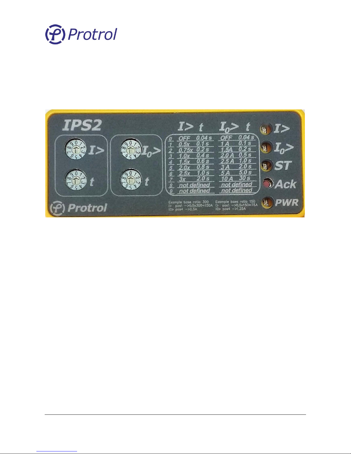
Figure 3. IPS2 24 VDC front panel HMI.
The yellow numbers in Figure 3 are explained in the following.
1. I> – A solid LED indicates a detected but unacknowledged overcurrent. A ½ Hertz flashing LED
indicates that there is a phase break.
2. I0> – A solid LED indicates a detected but unacknowledged earth fault. A ½ Hertz flashing LED
indicates a high I0.
3. ST – ST is a ½ Hertz flashing LED indicating correct operation.
4. Ack – Acknowledge button for LEDs. – Turns off the I0> LED, I> LED and the external LED.
5. PWR – PWR is lit when power is applied.
6. Rotary switch for overcurrent settings, start level as a nominal current multiplier.
7. Rotary switch for overcurrent settings, time in seconds.
8. Rotary switch for earth fault settings, start level in primary current.
9. Rotary switch for earth fault settings, time in seconds.
Rotary switches
After changing position of a rotary switch the IPS2 unit needs to be powered off/on or reset for the new
settings to come into effect. Keep the power off for at least 5 seconds before restoring the power supply.
To reach the reset button the front cover must be removed.
1
2
3
4
5
6 7 8
9
Page 12
Ver 1710 Rev 1
Protrol AB Tel: 031- 45 82 00
Ullevigatan 19 internet: www.protrol.se
411 40 Göteborg 12 e-mail: [email protected]
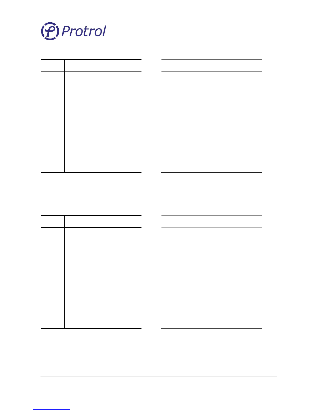
The I> pickup level setting is a per unit value related to the current transformer ratio.
Example: 300/1 ratio and pickup level 2.5 corresponds to a primary current level of
300 × 2.5 A = 750 A
The I0> pickup settings in Amperes are based on a current transformer ratio of 300/1. In the case a different
ratio is used the levels are scaled proportionally.
Example: 150/1 ratio and pickup level of 2 corresponds to a primary current setting of
150/300 × 2 A = 1 A
Position
0
OFF 1 0.5 2 0.75
3
1.0
4
1.5 5 2.0 6 2.5 7 3
8-9
Not used
Position
Pickup delay [s]
0
0.04 1 0.1 2 0.2 3 0.4 4 0.6 5 0.8 6 1.0 7 2.0
8-9
Not used
0
>
Position
Pickup level [A]
0
OFF 1 1.0 2 1.5
3
2.0
4
2.5 5 3 6 5 7 10
8-9
Not used
Position
Pickup delay [s]
0
0.04 1 0.1 2 0.2
3
0.5
4
1.0 5 2.0 6 5.0 7 30
8-9
Not used
Page 13
Ver 1710 Rev 1
Protrol AB Tel: 031- 45 82 00
Ullevigatan 19 internet: www.protrol.se
411 40 Göteborg 13 e-mail: [email protected]
5.3 Protrol Tool for IPS2
Protrol Tool is available for Windows 7/8.1/10 and can be downloaded from Protrol’s web page
(www.protrol.se).
5.4 Setting the IPS2 to Service Interface Mode
Set the jumper on the 3-pole header in position 1-2, see chapter “IPS2 24 VDC Main Printed Circuit Board
Rev. ” and figure 2.
Change the device protocol by pressing and holding the ACK button. Changed mode is indicated by a short
flash on the I0> LED.
5.5 Communication Cable
To be able to use Protrol Tool with the IPS2 24 VDC unit, a special 9-pole DSUB adapter cable with article
number 606535 is required. If the workstation lacks a physical COM port, which most new laptops do, a
special USB – COM converter must be added between the computer and the DSUB adapter cable. Such
adapter cables can be acquired where computer accessories are available.
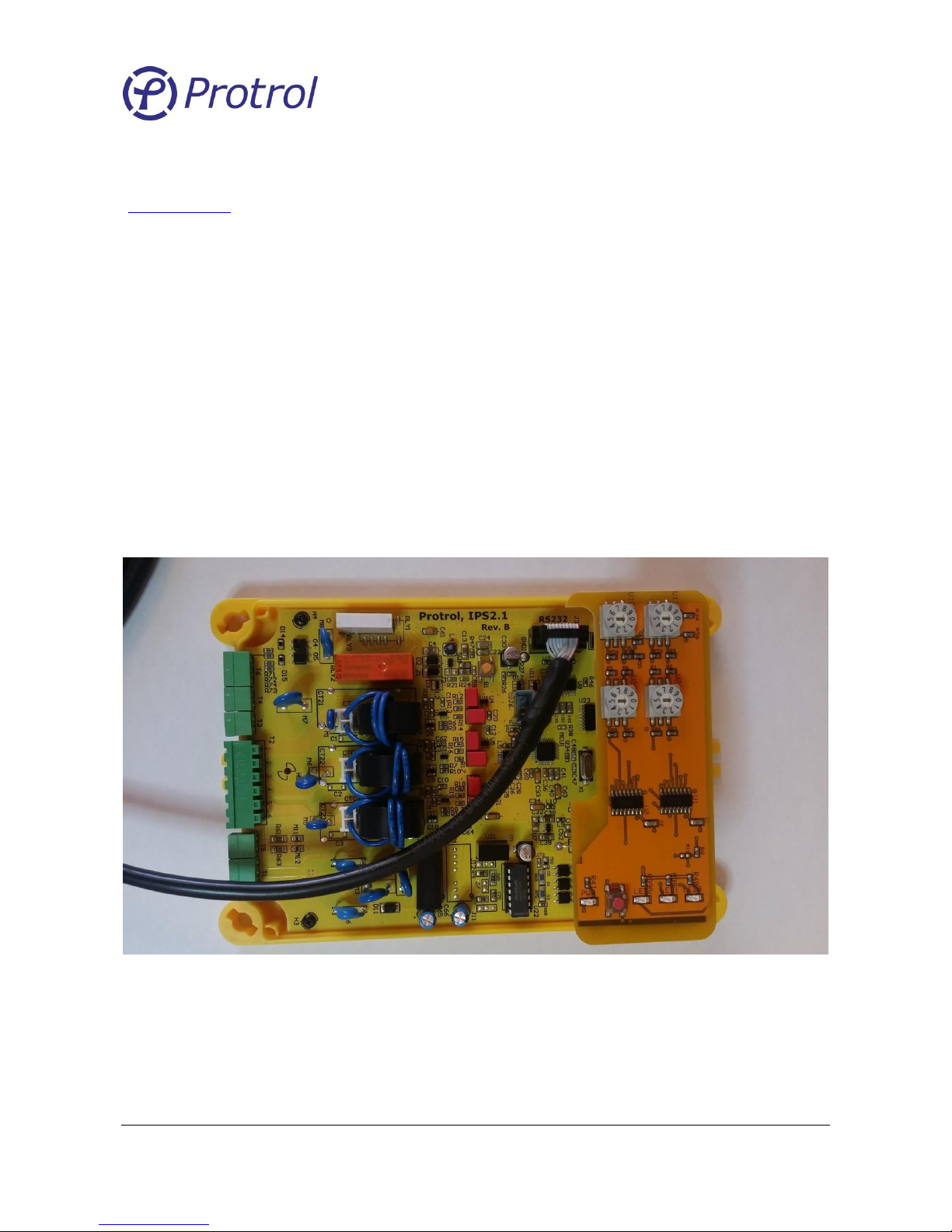
The service port connector is found on the upper side of the circuit board.
Note that the 3-pole header must have the jumper in position 1 – 2 to enable the Service Port.
Figure 4. The RS232 adapter cable is attached to the RS232 socket in the upper left corner of the Main PCB.
Page 14
Ver 1710 Rev 1
Protrol AB Tel: 031- 45 82 00
Ullevigatan 19 internet: www.protrol.se
411 40 Göteborg 14 e-mail: [email protected]
5.6 Protrol Main Window
Protrol Tool is used for the following IPS application:
▪ TFR, Transient Fault Recorder
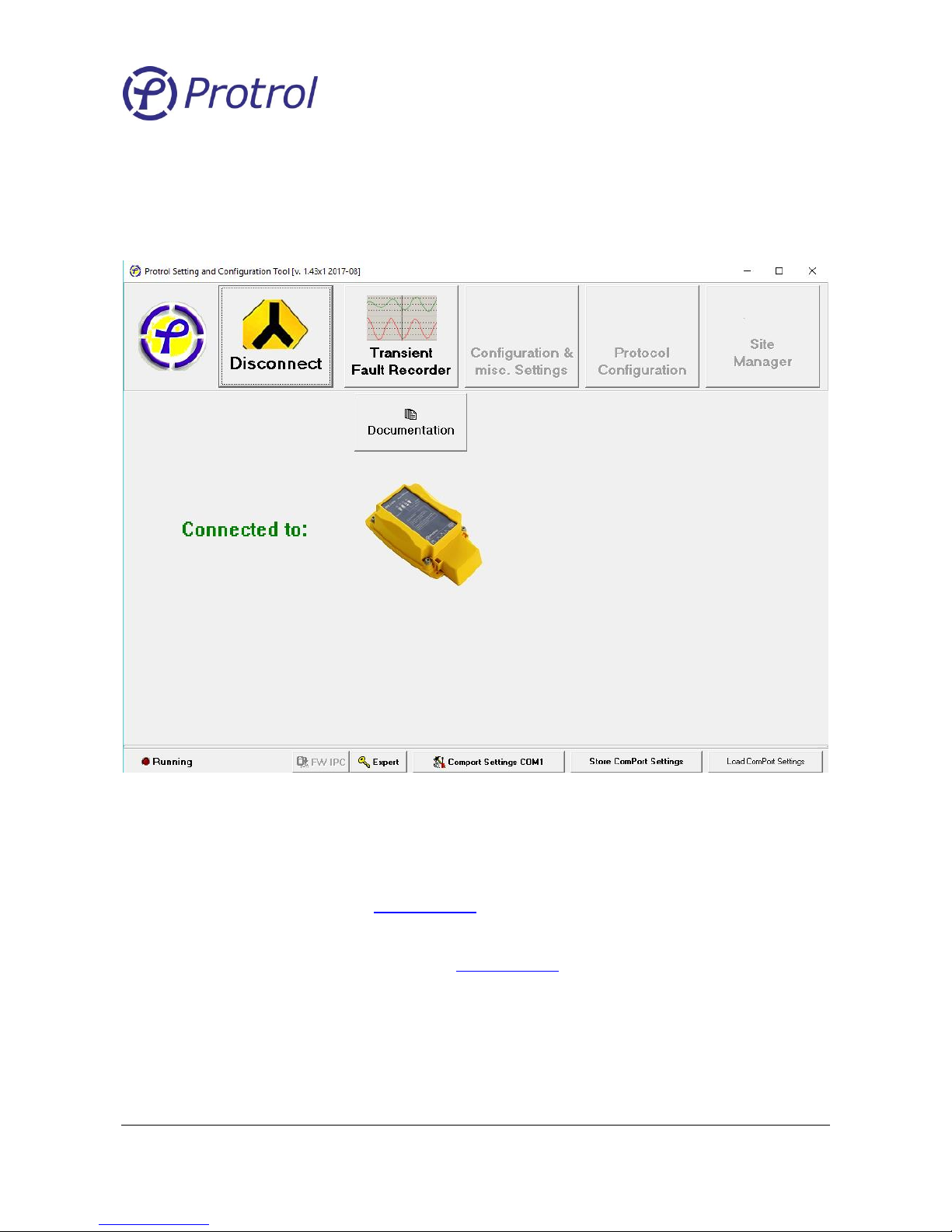
Figure 5. Protrol Tool main window.
Protrol Tool uses the serial port of the engineering workstation. However, this has in most computers been
replaced by the more common USB interface. Before using Protrol Tool for the first time, the corresponding
serial port - USB driver must be installed in your computer. If it will not be automatically installed by your
operating system, a link is available at www.protrol.se in the download section. When starting Protrol Tool
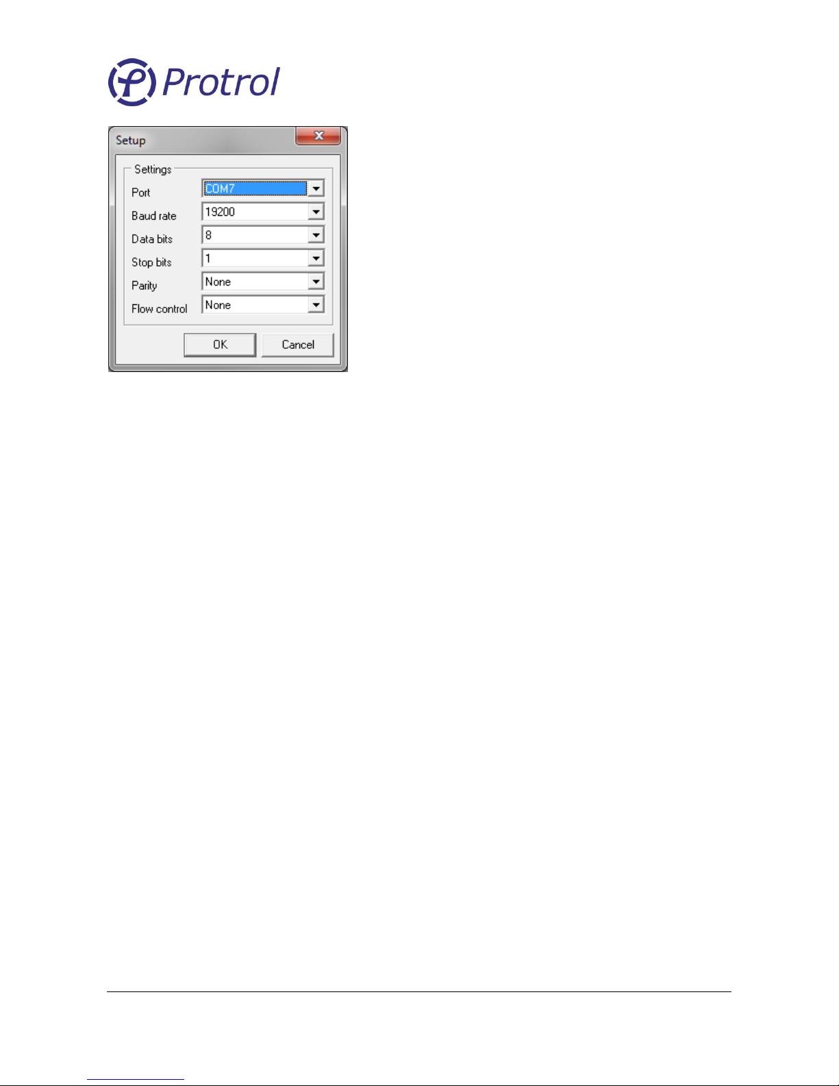
for the first time, verify that the COM port settings are correct, see Figure 6. The Port shall be the specific
COM port associated with the USB driver on the engineering workstation. A description how this is found is
available at the download page for Protrol Tool on www.protrol.se.
Page 15
Ver 1710 Rev 1
Protrol AB Tel: 031- 45 82 00
Ullevigatan 19 internet: www.protrol.se
411 40 Göteborg 15 e-mail: [email protected]
Figure 6. COM port settings pop-up. Important: Select the assigned USB - COM port!
Acknowledge by pressing OK and then try to connect by pressing Connect. If the dialog LED Running is
flashing, connection has been established.
Communication settings can be stored in the Registry by pressing the Store ComPort Settings button. Next
time Protrol-Tool is started the selected port is opened automatically.
Page 16
Ver 1710 Rev 1
Protrol AB Tel: 031- 45 82 00
Ullevigatan 19 internet: www.protrol.se
411 40 Göteborg 16 e-mail: [email protected]
5.7 IPS2 Transient Fault Recorder
The IPS2 detector has a built-in transient fault recorder which can be accessed from Protrol-Tool for further
analysis of the recordings.
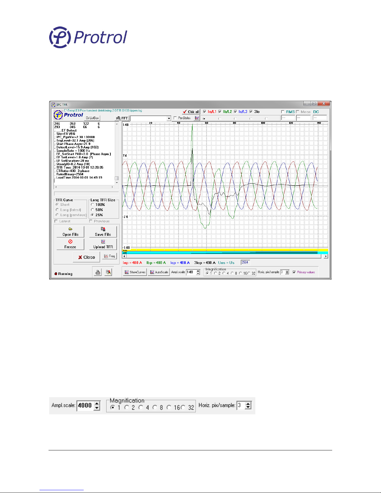
Figure 7. The Transient Fault Recorder
If the IPS detector has registered a fault, the Transient Fault Recordings, TFR, for the last faults can be
uploaded by pressing the Upload TFR button. A curve is three power frequency cycles with approximately
10 ms of prefault data.
By pressing the ShowCurves or AutoScale buttons, the TFR data will be displayed in the oscillogram. If
Primary values is checked the curves are scaled to primary values, otherwise they represent unscaled
binary values.
If AutoScale is not pressed the amplitude scale can be selected arbitrarily by changing the Ampl.scale field
shown in Figure 8 . Magnification of the amplitude axis is done in the Magnification field while Horiz.
pix/sample zooms in on the time axis.
Figure 8. The amplitude and time scaling fields.
Page 17
Ver 1710 Rev 1
Protrol AB Tel: 031- 45 82 00
Ullevigatan 19 internet: www.protrol.se
411 40 Göteborg 17 e-mail: [email protected]
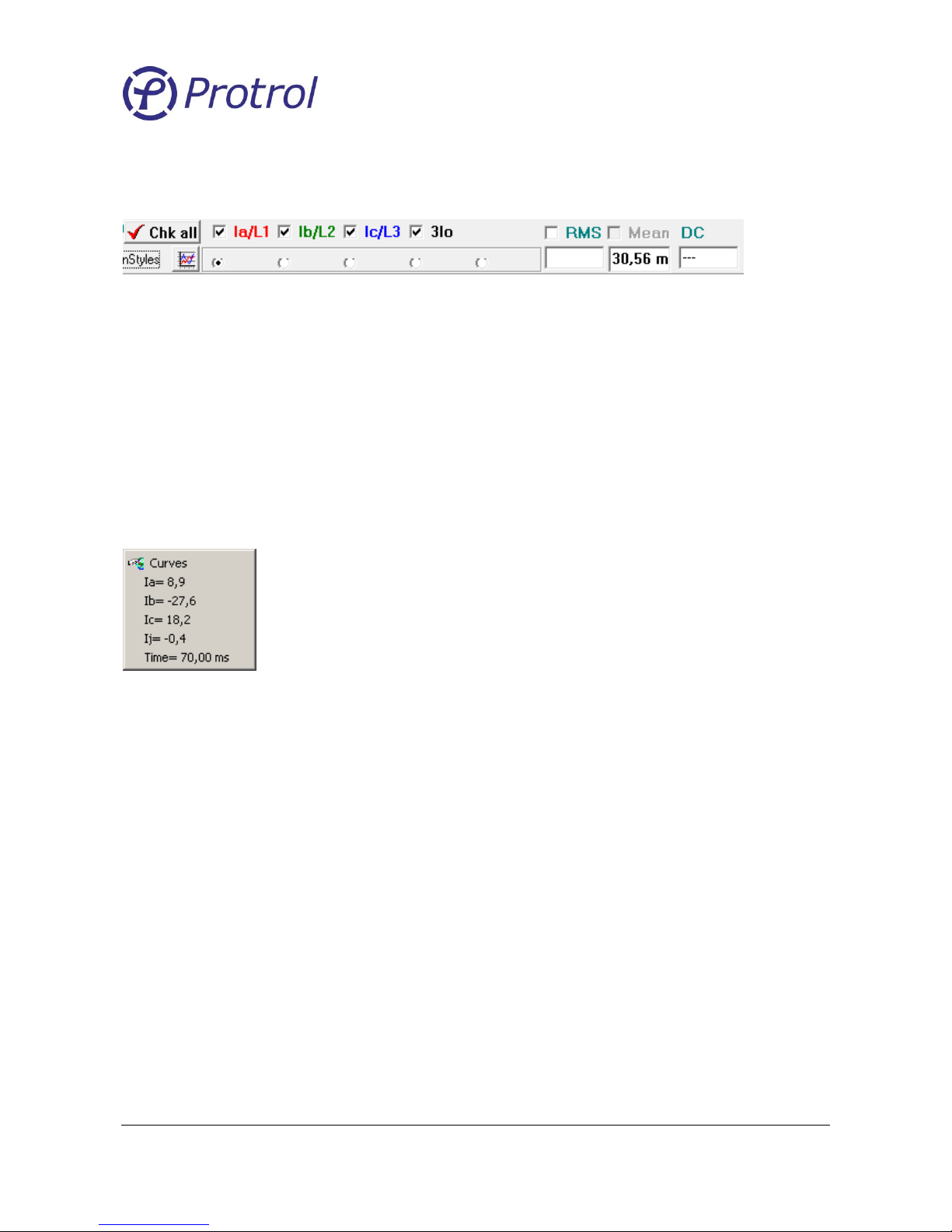
The Phase checkboxes above the oscillogram is used to display the signals graphically, while the radio
buttons below each signal are used for phase selection.
Figure 9. Checkboxes and radio buttons for graphical display options.
It is possible to trace a single curve. Select the curve of interest with the phase selection radio buttons
above the graph, then push the left mouse button on the graph and drag the cursor horizontally along the
time axis until the marker is at the desired location.
Each sample value is displayed numerically together with the time tag to the right of the phase selection
radio buttons. If the RMS checkbox is checked the corresponding RMS value for one cycle ahead of the
cursor is shown instead of the sample value.
Instead, if the right mouse button is pressed anywhere along a signal, all sample values at a given time are
displayed in a popup, see Figure 10.
Figure 10. Sample popup.
A useful feature of the transient fault recorder is the possibility to make a snapshot of the actual phase
currents by pressing the Freeze button and then the Upload TFR button. The Freeze button is not available
unless any registered faults have been Acknowledged (see Section 4.1Detector Function)! Observe that a
manually initiated TFR replaces the last saved TFR – it is therefore recommended to upload any recordings
of interest before a snapshot is made.
Please notice the scroll box to the left containing the samples as a numerical table. It also contains meta
information that describes the conditions when the recording was made. It is possible to add additional
observations or notes to the scroll box by starting each row with a “;”.
File Handling
When uploading a TFR from the IPS2 a question dialog is displayed asking for saving the file. This can also
be done later by pressing the Save File button. Saved files can be retrieved later by pressing the Open File
button.
Page 18
Ver 1710 Rev 1
Protrol AB Tel: 031- 45 82 00
Ullevigatan 19 internet: www.protrol.se
411 40 Göteborg 18 e-mail: [email protected]
6 Configuration of IPS2 24 VDC
6.1 Creating or Adjusting a Configuration File
Configuration of an IPS2 24 VDC is done with a stand-alone tool for Windows. This tool is used for basic
configuration and allows the user to create or edit settings for an IPS2, to save and load this information
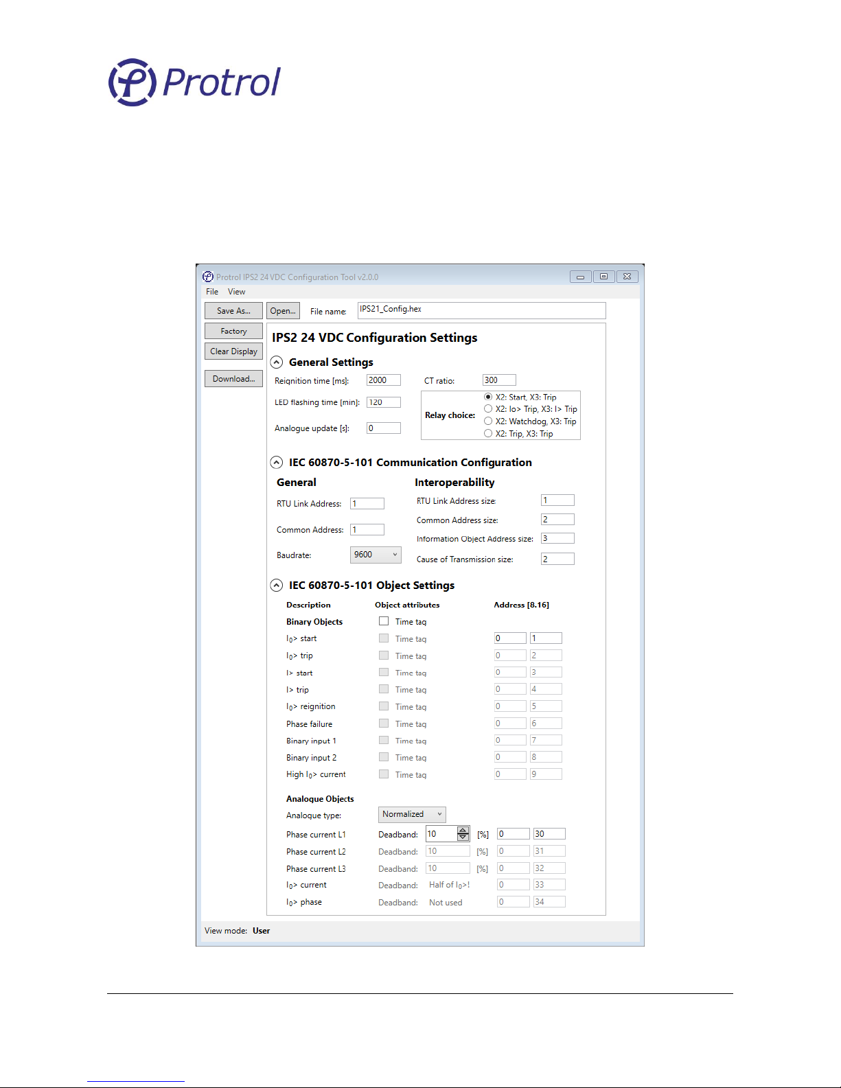
to/from disk and download a file to a unit. A screenshot of the configuration tool with factory settings is
shown in the figure below.
Figure 14. The Protrol IPS2 24 VDC Configuration Tool with factory settings.
Page 19
Ver 1710 Rev 1
Protrol AB Tel: 031- 45 82 00
Ullevigatan 19 internet: www.protrol.se
411 40 Göteborg 19 e-mail: [email protected]
IPS2 24 VDC Configuration Settings
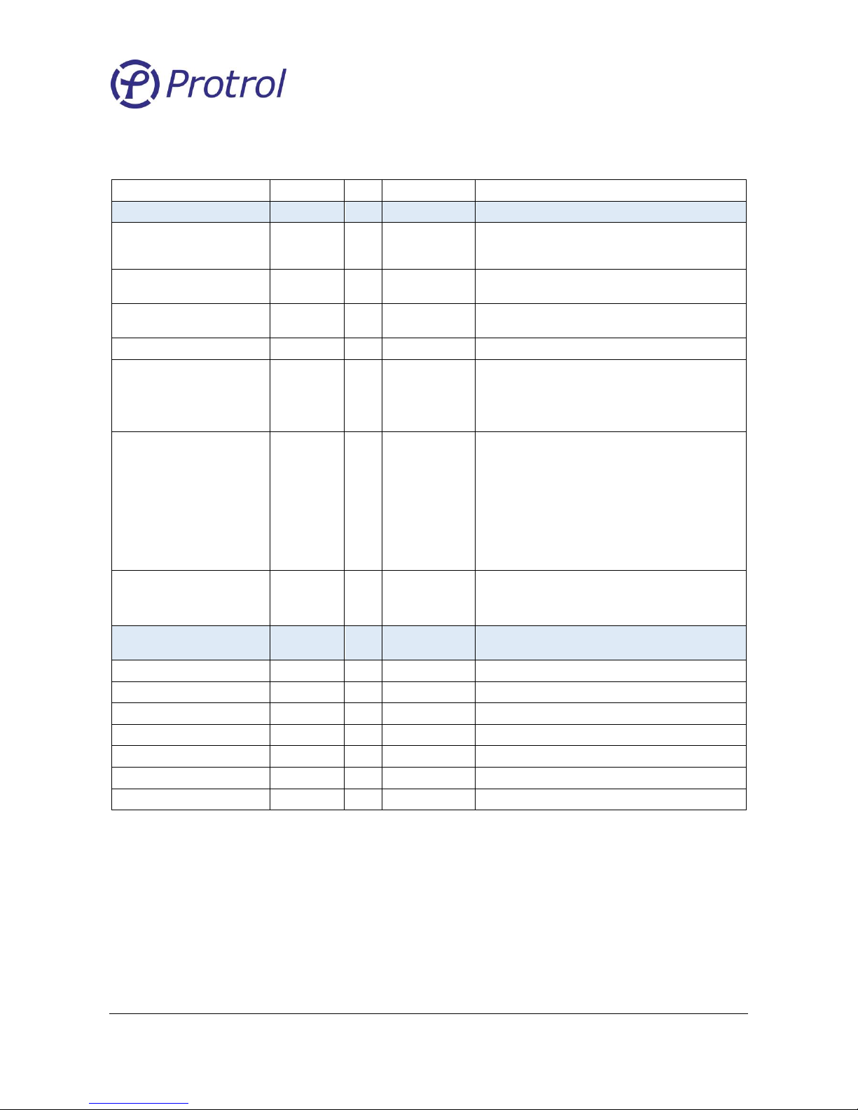
Table 1: Explanation of the Protrol IPS2 24 VDC Configuration settings.
Parameter
Range
Unit
Default
Comment
General Settings
Reignition time [ms]
0..10000
ms
2000
A reoccurring fault within the reignition time window
overrides the EF time rotary switch and sets the operate
time to a minimum. 0 disables the reigniting faults function
LED flashing time [min]
0..1440
min
120
The flashing time of the external LED in minutes also is used
to acknowledge the front panel indication LEDs.
Analogue update [s]
0..65535 s 0
Cyclic update of analogue values. No cyclic update if the set
value is 0, however, the deadband is activated instead
CT ratio
50..1200 - 300
Relay choice
0..3 - 0
0: X2: Start, X3: Trip.
1: X2: EF Trip, X3: OC Trip
2: X2: Watchdog, X3: Trip (Hardware version 3 only)
3: X2 and X3: General Trip
Operation mode
0..1 Bit 5: On
All other: Off
Checkbox 7: DIR bit in balanced mode
Checkbox 6: Balanced mode
Checkbox 5: Send analog objects
Checkbox 4: Time tag
Checkbox 3: Not used
Checkbox 2: Not used
Checkbox 1: See relay choice
Checkbox 0: See relay choice
OC level shift factor
0..8 - 0
0: Not used
1: Trip level divided by 2
2: Trip level divided by 4, etc.
IEC 60870-5-101 Communication
Configuration
RTU Link Address
1..255 - 1
Common Address
1..65534 - 1
Common Address of ASDU
RTU Link Address size
1..2 - 1
Number of octets for RTU Link Address
Cause of Transmission size
1..2 - 2
Number of octets for Cause of Transmission
Common Address size
1..2 - 2
Number of octets for Common Address
Information Object Address size
1..3 - 3
Number of octets for Information Object Address
Baudrate
9600, 19200
bit/s
9600
Standard rates for the IEC-101 port
Page 20
Ver 1710 Rev 1
Protrol AB Tel: 031- 45 82 00
Ullevigatan 19 internet: www.protrol.se
411 40 Göteborg 20 e-mail: [email protected]
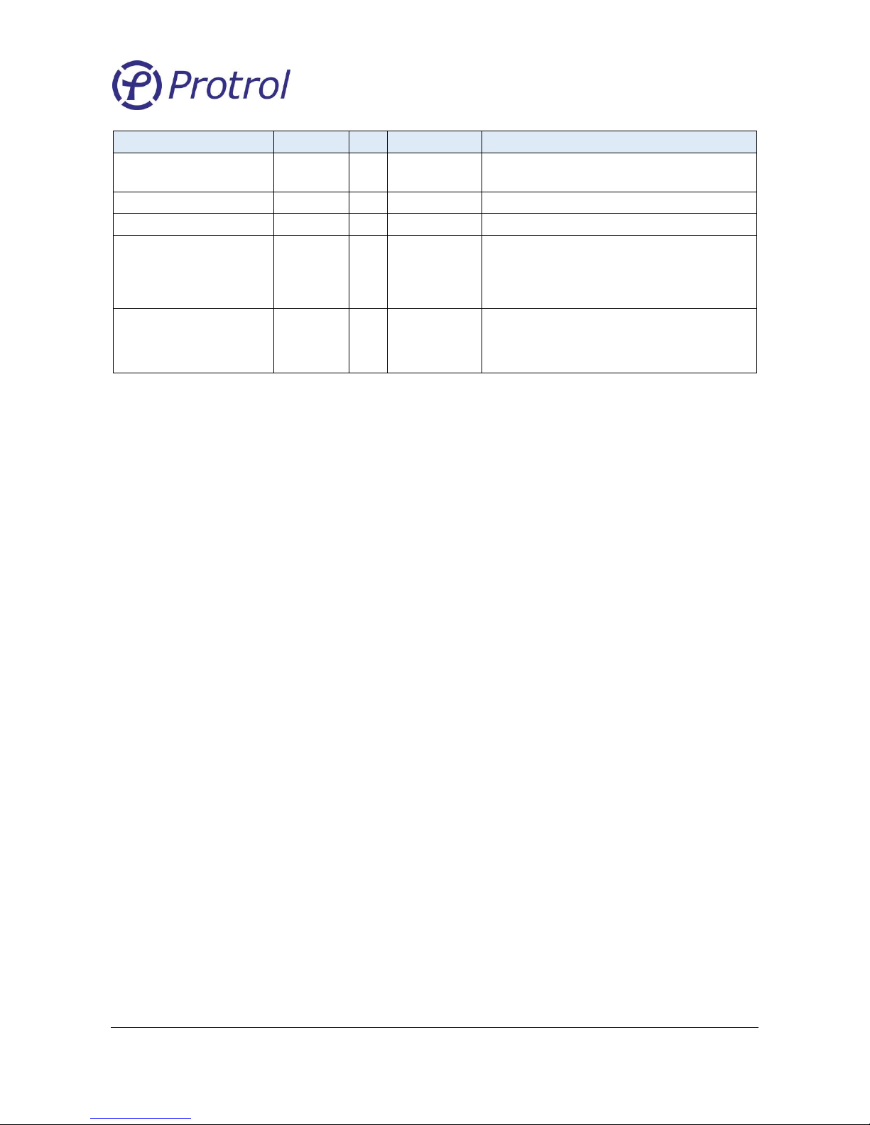
IEC 60870-5-101 Object Settings
Time Tag
0..1 0
0: No time tag included
1: Time tag included
Address [8]
1..255 0
The highest address octet
Address [16]
0.. 65534 1 to 9
The two lowest address octets
Analogue type
0..3 1
0: Raw, rated current 3800 units
1: Normalized to the nominal CT ratio
2: Scaled to integer primary current in Amperes.
3: Floating point primary current in Amperes
Deadband
1..50 % 10
Deadband for the update of analogue objects in percent of
rated current (CT ratio)
Remark: The deadband for I0 is half of the I0 setting. If the I0
stage is disabled, the deadband is 2.5 A
Factory Defaults
It is possible to reset all settings in the configuration tool to factory defaults by pressing the Factory button.
Open Configuration File
Previously saved settings can be reloaded to the configuration tool by pressing the Open button. A dialog
opens and it is possible to browse and choose the desired configuration file. Press Open to read the file.
Edit Configuration Data
After the Factory or Open buttons have been pressed it is possible to adjust configuration data.
Save Configuration File
The current settings can be save by pressing the Save button. A dialog opens and it is possible to adjust the
file name before Save is pressed a second time.
Clear Display
It is possible to clear all settings in the configuration tool by pressing the Clear Display button.
Download Configuration File
The current configuration file can be downloaded to a connected IPS2 unit by pressing the Download…
button. Please see the chapter “Download a Configuration File to the IPS2 Device” for detailed information
and instructions.
Page 21
Ver 1710 Rev 1
Protrol AB Tel: 031- 45 82 00
Ullevigatan 19 internet: www.protrol.se
411 40 Göteborg 21 e-mail: [email protected]
6.2 Download a Configuration File to the IPS2 Device
Equipment and preparation
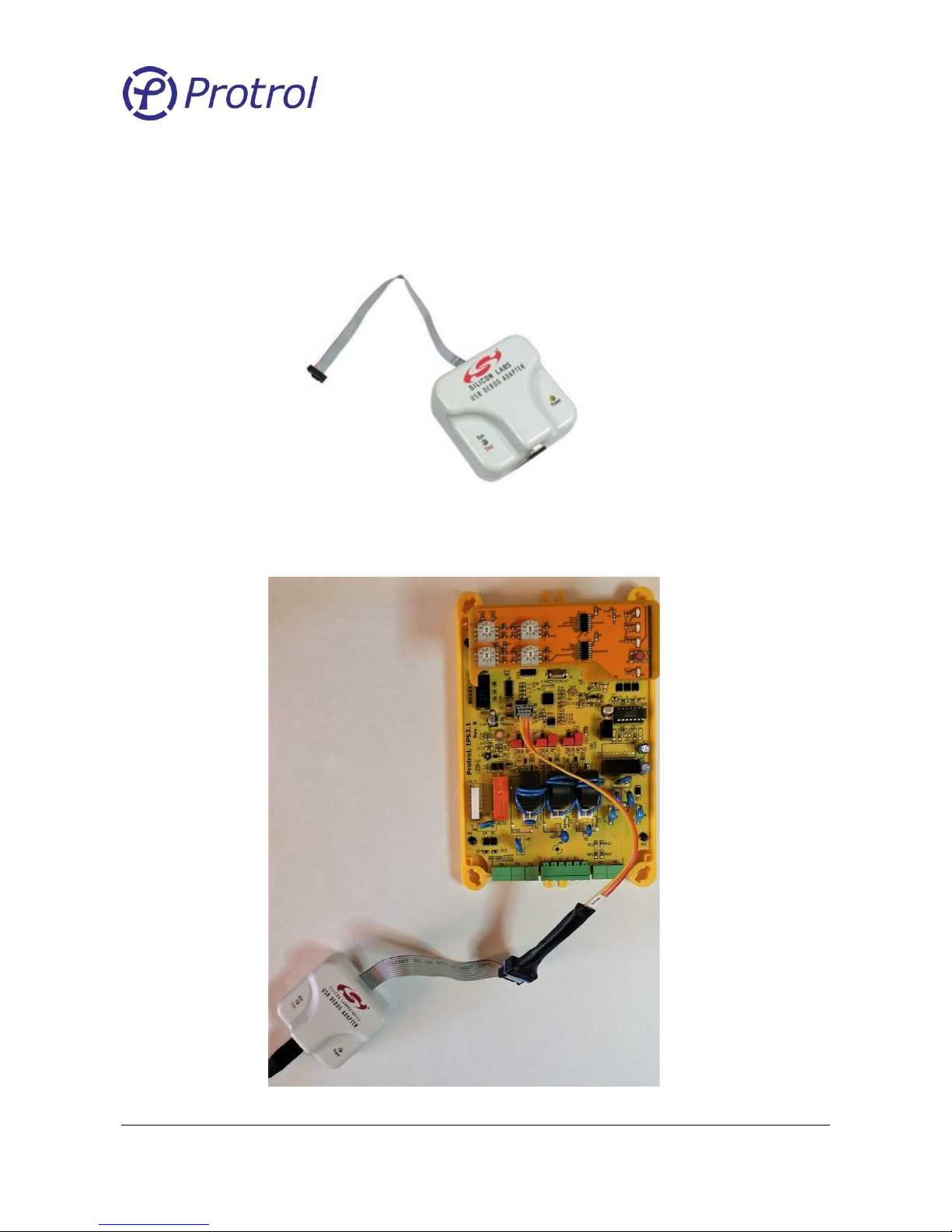
For downloading configurations to an IPS2 a USB Debug Adapter for C8051Fxxx from Silicon Labs and
corresponding software is needed.
Figure 15. 8-Bit USB Debug Adapter.
The adapter shall be connected to the C2 contact on the IPS2. For that you need a special cable that can be
ordered from Protrol, article number 606537. See figure below.
Figure 16. USB Debug Adapter connected to IPS2.
Page 22
Ver 1710 Rev 1
Protrol AB Tel: 031- 45 82 00
Ullevigatan 19 internet: www.protrol.se
411 40 Göteborg 22 e-mail: [email protected]
Connect the adapter to the maintenance PC using an USB cable.
The needed extra files for the adapter are included in the Protrol IPS2 24 VDC Configuration Tool
installation package, version 2.0.0 and higher. Make sure that you have the files “SiUtil.dll” and
“USBHIB.dll” in the same folder as the configuration tool.
Downloading configuration file
Follow the steps below to download the configuration file.
1. Connect the IPS2 device as described above.
2. Power-up the IPS2.
3. Start the Protrol IPS2 24 VDC Configuration Tool (if not already started).
a. Make sure you have version 2.0.0 or later of the tool.
b. Check also that you have the files “SiUtil.dll” and “USBHIB.dll” in the same folder as the
configuration tool.
4. Open the configuration file to download (the Open… button)
or make sure you save the settings you currently made (press the Save As… button).
a. Please observe that the download function only uses the file name in the field and
download that file to the IPS unit. It will not check for any differences or unsaved settings in
other settings fields.
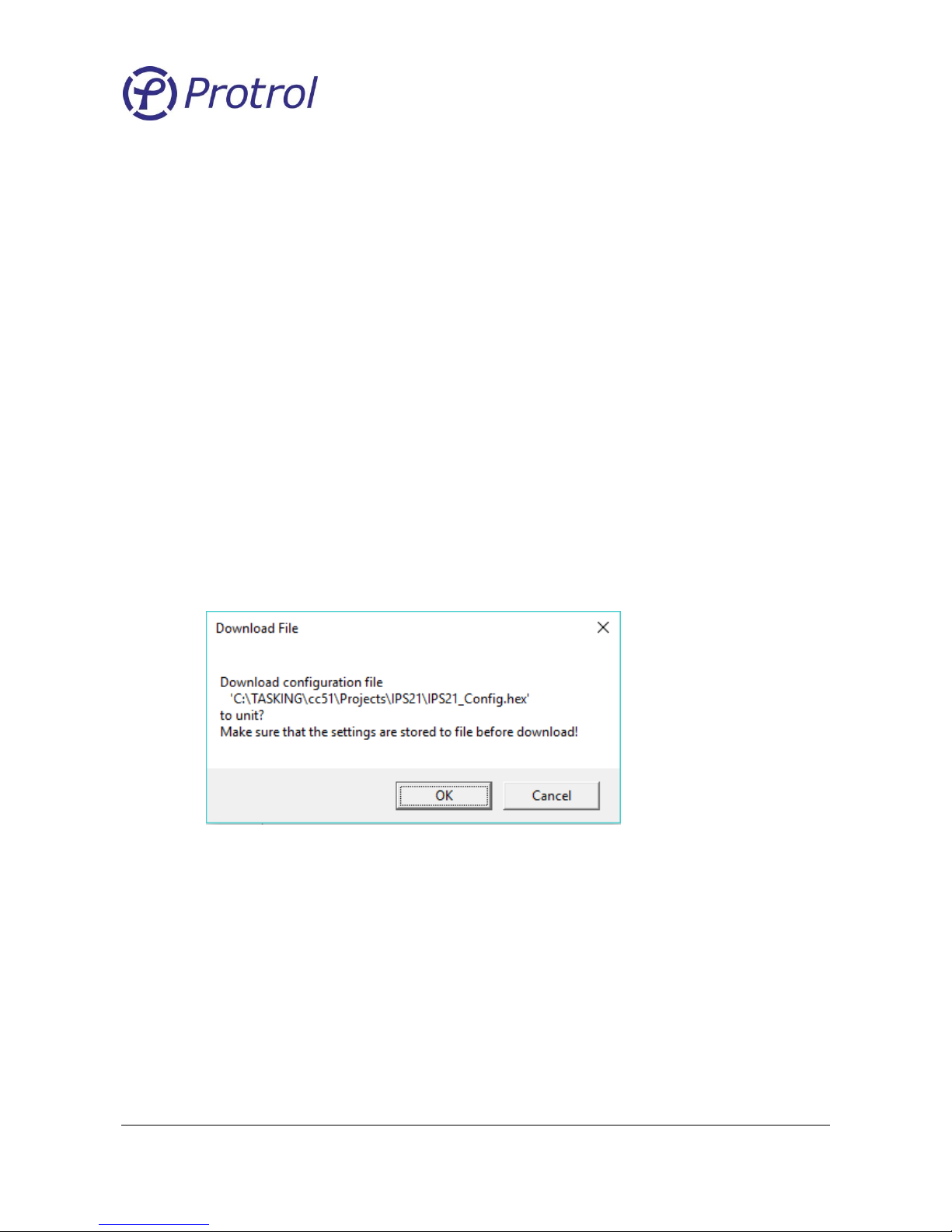
5. Press the Download button.
6. Press OK.
a. A confirmation dialog will be displayed with information.
7. Done!
Page 23
Ver 1710 Rev 1
Protrol AB Tel: 031- 45 82 00
Ullevigatan 19 internet: www.protrol.se
411 40 Göteborg 23 e-mail: [email protected]
7 Testing and Commissioning of IPS2
Before taking an IPS unit into operation it can be tested either in off site or installed in the station. It can be
tested with a single current source for both overcurrent and earth fault functions.
7.1 Binary I/O
Test of Binary Inputs
Apply a test voltage to the binary inputs and verify that the IPS2 unit detects the signals and transmits them
to the dispatch centre.
7.2 Current Injection Test
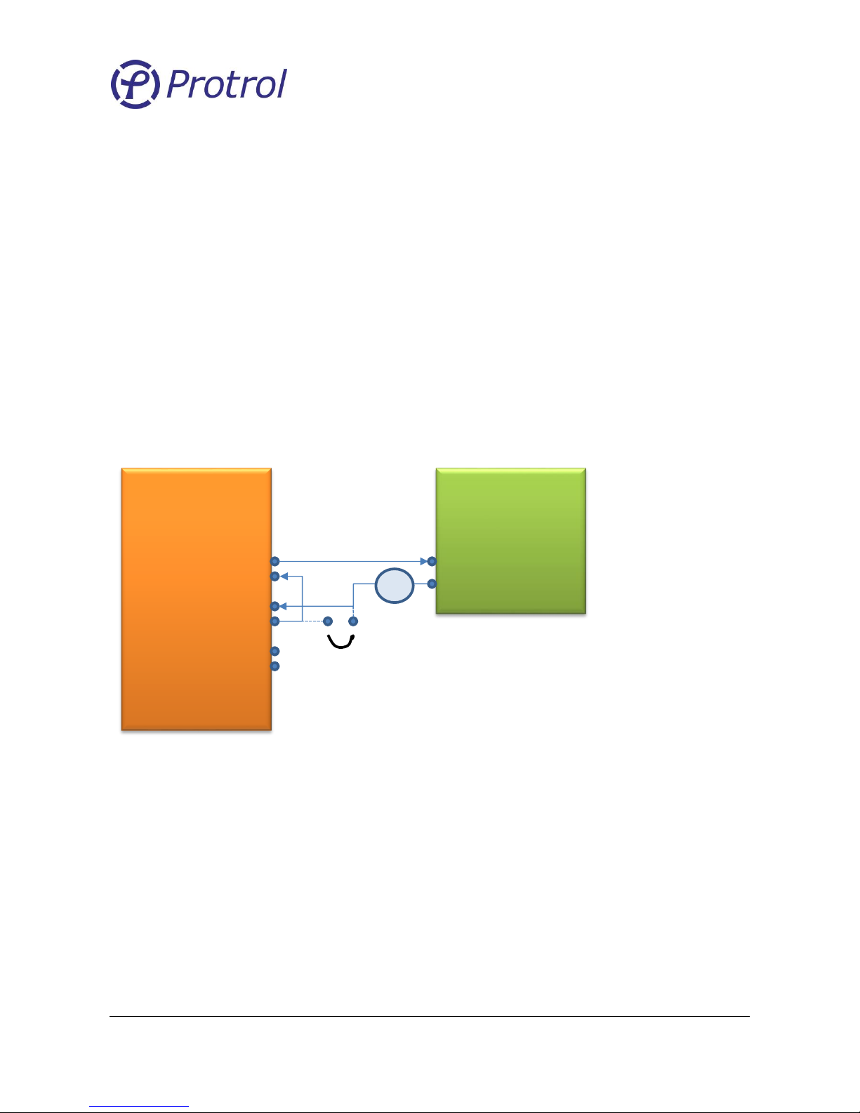
Test circuit
Connect the current source to phases A and B (or any other combination of two phases) according to Figure
11. Apply a current of 0.5 A. The measured sum of the phases shall now be zero. Verify with the built-in
transient fault recorder of Protrol Tool. See section below for details.
Figure 11. Current injection test.
Overcurrent Test
Increase the current of the current source until overcurrent is detected. This is indicated by the OC LED and
the output relay will close for the set time, if applicable. Note: If an input is used to release the output
signal this input must be set high.
Verify that the OC Start and Trip signals are transferred to the dispatch center.
IPS
Current
Source
1 A
Page 24
Ver 1710 Rev 1
Protrol AB Tel: 031- 45 82 00
Ullevigatan 19 internet: www.protrol.se
411 40 Göteborg 24 e-mail: [email protected]
Earth Fault Test
Put a short circuit over one of the phases according to the drawing above using a short test cord. The
current in the short circuit will simulate the measured earth current, and needs to be applied longer than
the set Operation Delay. Earth fault detection is indicated by the EF LED and closing of the output relay, if
applicable. If connected to a PC, check the transient fault record using Protrol-Tool.
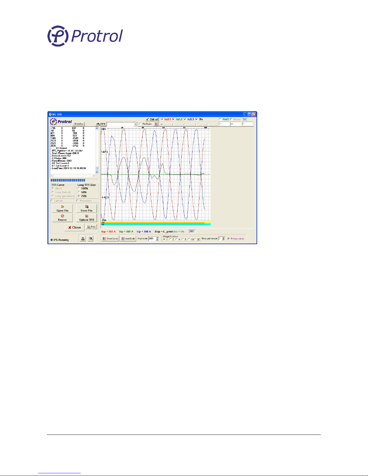
A typical recording from an earth fault test is shown in Figure 12.
Figure 12. Typical transient fault recording after an earth fault test.
Verify that the EF Start and Trip signals are transferred to the dispatch center.
7.3 EF Trig Level Check
After connection to the current transformers, verify that the EF LED does not flicker vaguely. This indicates
that the EF Trig Level may be set too low.
7.4 Test of IPS after Commissioning
Testing of earth fault detection is possible by simply short circuiting one of the three phases directly on the
input terminal. Disconnect the output relay to avoid any unwanted actions. There must be a primary
current (at least a few Amperes) in all three phases.
7.5 Offset Elimination (zero offset calibration)
A zero-offset calibration is made during manufacturing.
If needed a calibration can also be manually made.
Follow the steps below to initiate a calibration:
1. Short circuit and disconnect the current terminals.
2. Press and hold the Ack button while power cycling the device.
3. Release the Ack button when the ST LED turns on.
4. The I
0
> LED should now start flashing to indicate the calibration phase.
Page 25

Ver 1710 Rev 1
Protrol AB Tel: 031- 45 82 00
Ullevigatan 19 internet: www.protrol.se
411 40 Göteborg 25 e-mail: [email protected]
Protrol AB, Ullevigatan 19, 411 40 Göteborg
Tel: 031-45 82 00. E-post: [email protected]
www.protrol.se
 Loading...