

Proton HD P1-E-7020, HD P1-F-7015, HD P1-E-7015, HD P1-T-7015, HD P1-T-7020 Operation Manual
...Page 1

OPERATIONS MANUAL
FOR INDUSTRIAL CURTAINS
PROTON HEAT DOOR P1
ErP
2015
05010416
Water heating
Electric heating
Without heating
www.protongroup.org
Safety precautions
Construction and dimensions
Technical parameters
Installation
EN
RU
Page 2
CONTENTS
Maintenance guide for industrial curtains PROTON HEAT DOOR P1:
1. Introduction ...........................................................................................................................................................
2. Safety precautions .............................................................................................................................................
3. General information ...........................................................................................................................................
4. Dimensions ............................................................................................................................................................
5. Construction .........................................................................................................................................................
6. Technical characteristics .................................................................................................................................
7. Installation ............................................................................................................................................................
8. Connection of heat medium ...........................................................................................................................
9. Control elements ................................................................................................................................................
10. Wiring control elements ..................................................................................................................................
11. Reference information ....................................................................................................................................
3
4
5
6
7
8
10
11
12
13
15
2
Page 3
1. INTRODUCTION
The company PROTON GROUP LLC thanks you for choosing
industrial curtains PROTON HEAT DOOR P1.
This manual is an integral part of the product and must
always accompany it, and should be transferred to the user.
To provide proper wiring and application of the industrial
curtain, please, study this manual thoroughly before
installation.
We recommend keeping the manual safe in order to address
it during operation and maintenance.
The user should strictly follow safety instructions while
installing, using and servicing the unit.
The access to the unit must be restricted for unauthorized
and unqualified personnel. The appropriate training of the
maintenance sta should be provided.
The manufacturer disclaims any responsibility for damage
caused by wrong installation and misuse of the unit.
The manufacturer disclaims any responsibility for damage
done by people who didn’t study the manual.
The manufacturer preserves the right to introduce any
amendments to the manual without prior notification.
The manufacturer preserves the right to alter the
construction which doesn’t impact its functioning and basic
technical parameters.
The industrial curtain is intended only and exclusively to be
installed and used for purposes which it has been designed.
Any misuse or noncompliance with the manufacturer’s
instructions may lead to property damages, personnel injuries
or death. The user has to take measures to eliminate
possibilities of wrong operation of the curtain.
3
Page 4
2. SAFETY PRECAUTIONS
Before any actions connected with the air curtains, please, study
this manual to provide safety.
Installation and connection of the equipment to pipelines and
networks must be performed by qualified personnel only,
having appropriate access.
During installation, start-up, repair and maintenance of the
industrial curtain follow the safety rules.
Install the industrial curtain on a firm base or surface, which
can stand its weight filled with water.
Use screws appropriate for the material which the base is
made of.
Check correctness of wiring of the system, accordance of the
heat medium parameters with the parameters indicated on
the rating plate as well as leak proof of joints before filling in
the heat medium.
Avoid substances and impurities in the heat medium causing
copper corrosion.
Check compliance of parameters of the electrical supply
network indicated on the industrial curtain’s rating plate
before connecting to the power supply.
Check grounding. Prohibit the use of the equipment without
grounding as it may cause property damages, personnel
injuries and death.
Current network which feeds the curtain’s motor and controls
must be additionally protected by a fuse to prevent
consequences of shunt fault.
Thermal protection of fan motor is built-in and works in a
standalone mode.
While unit operating under low temperatures, the user must
-t
provide protection of the water heat exchanger or use heat
medium with special additives preventing copper corrosion.
To prevent defrosting of the industrial curtain’s heat
exchanger when circulation of the heat medium is stopped
during a heating period under outdoor temperatures lower
than 0°C, you need to drain the heat medium from the heat
exchanger and blow it o by compressed air.
4
Page 5
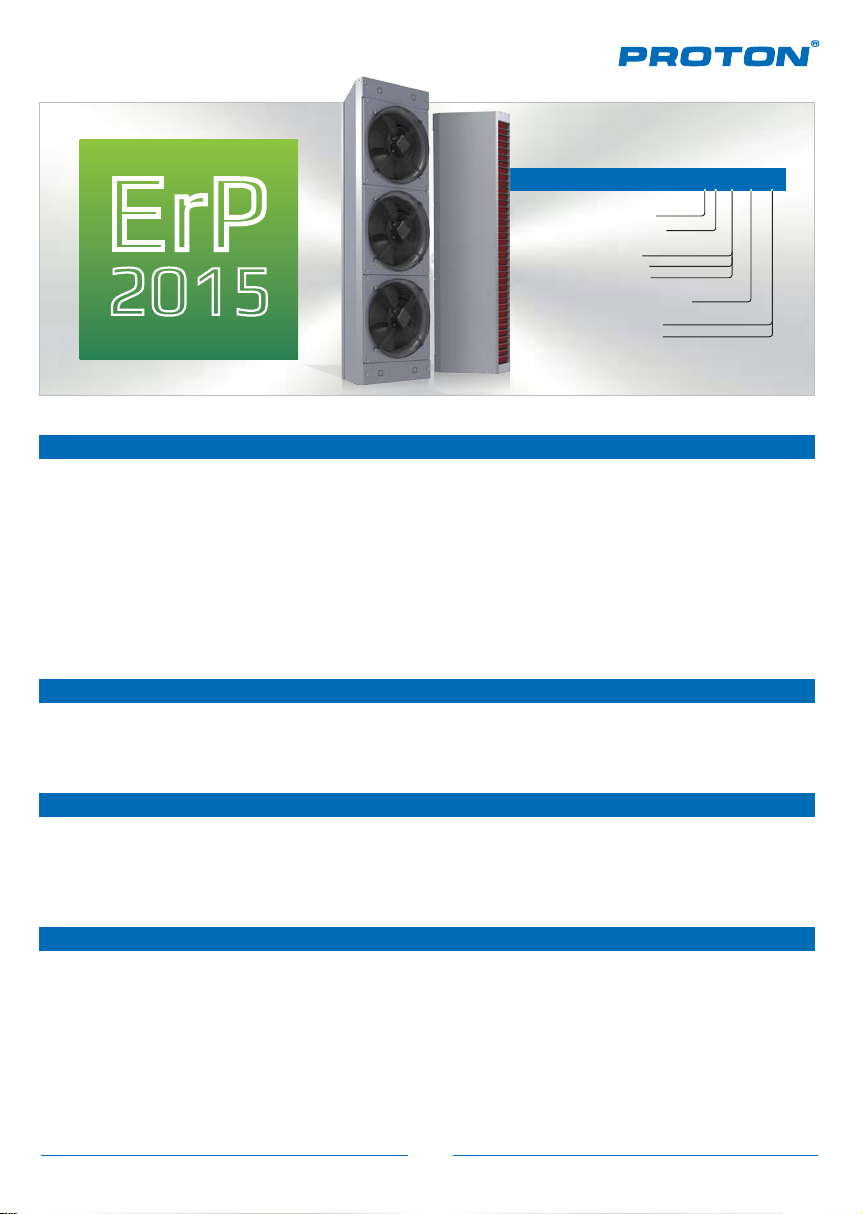
3. GENERAL INFORMATION
PROTON HD P1-T-7015
P – industrial curtainP – industrial curtain
ErP
2015
PROTON HEAT DOOR P1
This is an industrial curtain of high eciency. The products of this series are used to create a barrier in
form of a powerful air stream, which covers door and gateways in buildings where maintenance of
constant climatic conditions is required. The air curtains PROTON HEAT DOOR P1 successfully solve the
problem of heat losses in buildings by cutting o cold or hot outdoor air, and prevent access of dust,
insects, gases, etc. The air curtains are a reliable and valuable solution for energy saving and
separation of climate.
Construction of the air curtains allows to mount them as modules choosing appropriate angle of
curtains installation, and revolving louvers direct the air into the needed area. Wide range of heating
options makes decision-making easier in any buildings.
1– single-phase motor1– single-phase motor
T – water heating
T – water heating
E – electric heating
E – electric heating
F – without heating
F – without heating
70 – distance of air stream70 – distance of air stream
15 – length 1500 mm
15 – length 1500 mm
20 – length 2000 mm
20 – length 2000 mm
Heating curtains with water heating
Heating curtains apply hot water as a heat medium. They are very ecient and powerful, save money
and require low overhead and operating costs.
Electric heating
These air curtains apply electric heating elements as a heat medium. The advantage of this equipment
is that it is easy and simple to install. Electric curtains are optimal solution for buildings where there is
no hot water supply and its use is unreasonable.
Without heating
Curtains without heating are designed for cutting o outdoor air in doorways of the conditioned
buildings, refrigerators, where ingress of outdoor air is undesirable. This type of curtains is very
eective for preventing access of dust, insects, gases, etc.
5
Page 6
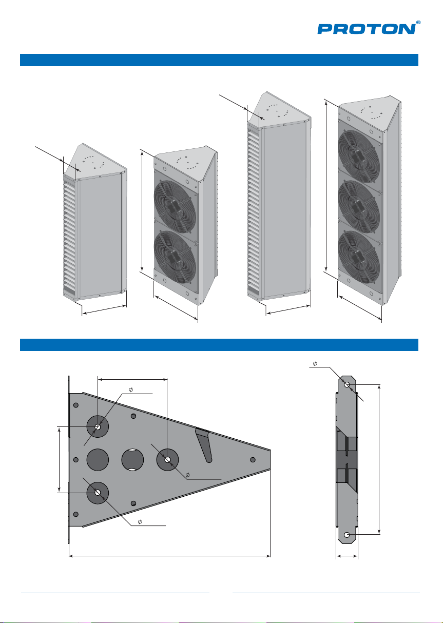
4. DIMENSIONS
Dimensions of industrial curtain PROTON HEAT DOOR P1
100
1500
100
2000
560
590
Dimensions of a mounting console СM HD
160
13.2
150
13.2
462
560
590
12
344
13.2
50
6
Page 7

5. CONSTRUCTION
PROTON HEAT DOOR P1
1
3
4
1. Casing.
2. Side panel.
3. Diusor.
4. Axial fan.
5. Heat exchanger or Finned tubular
electric heating elements.
5
Major components of the industrial curtain
PROTON HEAT DOOR P1:
Casing
The casing consists of galvanized or dyed
2
metal.
Single-phase AC-fan
Rated power supply is 230 V/50 Hz. Motor
protection grade is IP54, F-isolation class.
Operating temperature is up to +60°C.
Directing louvers
They are made of steel and dyed with special
paint and provide minimal air resistance at
the outlet from the curtain. Modern look and
high protection from corrosion guarantee long
life and safety.
Heat exchanger
The heat exchanger consists of copper tubes and aluminum lamellas pressed on them. It is equipped
with copper pipes with threading connection (external thread 3/4”). The copper-aluminum heat
exchanger is distinguished by high eciency, is not exposed to corrosion if a prepared heat medium
with no additives causing copper corrosion is used. Maximal parameters of heat medium supply
are 105 °C/1,6 MPa.
Finned tubular electric heaters
The heating elements, installed into the curtains, are made of high-alloy stainless steel. For better
heat extraction, toroid-like coils with width of 10 mm with additional corrugation are added to these
heating elements. The frame for mounting is made of galvanized steel. Joint boxes are equipped with
clamping cables. Thermal sensors of overheat protection of the finned tubular electric heaters are
fastened on their top and bottom sides.
7
Page 8

6. TECHNICAL PARAMETERS
6.1 Industrial curtains with water heating PROTON HD P1-T-70
General parameters
Air curtain’s standard size
Airflow
Heat power
Max. warm air throw
Air temperature increase
Volume of water in heat exchanger
Noise level
Max. temperature of heat medium
Max. working pressure
Diameter of connection pipes
Weight
Supply voltage of the curtain
Rated current of the curtain
Power of motors
Motor protection rating
Dimensions (WxHxL) Габариты (Ш х В х Г)
mm
m³/h
kW
m
°С
dm³
dB
°С
MPa
inch
kg
V/Hz
А
W
IP
mm 1500 х560 х590 2000 х560 х590
Parameters according to the heat medium
(°С)
Qp
(m³/h)
T /zT
p
P
p1
(°С)
0
5
10
15
790010900
20
25
Water 90/70 Water 80/60 Water 70/50 Water 60/40Parameters
P
g
54.8
51.4 29.124.3 2.3
47.9 25.6
44.5 22.3
41.0 19.135.3 1.8
37.5
Q
P
w
p2 p
(m³/h) (kW) (kPa)
(°С)
28.0 2.1
31.6 2.0
32.720.6 2.4
HD P1-T-7015 HD P1-T-7020
1500
7900
54.8 75.0
7.0
20.6
3.28
68
105
1.6
3/4
62.6 71.5
230/50
4.0
840
54
HD P1-T-7015
47.3
43.8
40.4
36.9
33.3
29.8
P
g
Q
P
w
p2 p
(m³/h) (kW) (kPa)
(°С)
17.8
2.1
21.5
1.9
25.1
1.8
28.8
1.6
32.4
1.5
36.016.238.9 1.7
1.3
25.4
22.1
19.0
16.1
13.4
10.9
39.8
36.3
32.7
29.2
25.6
22.0
P
g
Q
P
w
p2 p
(m³/h) (kW) (kPa)
(°С)
15.0
1.7
18.6
1.6
22.3
1.4
25.9
1.3
29.5
1.1
33.2
1.0
18.9
16.0
13.3
10.8
8.5
6.2
32.2
28.6
25.1
21.5
17.8
14.1
P
g
230/50
2000
10900
7.0
20.5
4.42
70
105
1.6
3/4
6.0
1260
54
P
p2 p
(°С)
12.1
15.8
19.4
23.0
26.6
30.2
Q
w
(m³/h) (kW) (kPa)
13.2
1.4
10.7
1.3
1.1
8.4
0.9
6.3
0.8
4.5
0.6
3.0
Parameters according to the heat medium
(°С)
T /zT
p
Qp
(m³/h)
(°С)
P
p1
0
5
10
15
20
25
– water temperature at the inlet of the industrial curtain
P
z
P
– water temperature at the outlet of the industrial curtain
p
Q
– water consumption
w
Q
– air consumption
p
Data on operat ing characteris tics of indust rial curtains PROTON HEAT DOOR P1 when using hea t medium with diering tempe ratures is to b e provided on
demand.
There is danger of heat exchanger defrosting (breakage) if room temperature falls lower than 0 °C.
As maximal pressure of heat medium is 1,6 MPa, water circuit system must have protectio n from pressure rise h igher than accepted va lue.
P
75.0
70.3
65.5
6.7
55.9
51.1
g
Water 90/70 Water 80/60 Water 70/50 Water 60/40Parameters
Q
P
w
p2 p
(m³/h) (kW) (kPa)
(°С)
20.5
3.3
24.1
3.1
27.8
2.9
31.4
2.7
35.1
2.5
38.7
2.3
26.5
23.4
20.5
17.8
15.3
12.9
64.6
59.8
55.0
50.2
45.3
40.4
P
g
P
p1
P
p2
P
g
p
HD P1-T-7020
Q
P
w
p2 p
(m³/h) (kW) (kPa)
(°С)
17.6
2.8
21.3
2.6
24.9
2.4
28.6
2.2
32.2
2.0
35.8
1.8
– air temperature at the inlet of the industrial curtain
– air temperature at the outlet of the industrial curtain
– heat power of the industrial curtain
– water pressure drop in heat exchanger
20.3
17.6
15.1
12.7
10.5
8.5
54.1
49.3
44.5
39.6
34.6
29.6
P
g
Q
P
w
p2 p
(m³/h) (kW) (kPa)
(°С)
14.8
2.4
18.4
2.2
22.1
1.9
25.7
1.7
29.3
1.5
33.0
1.3
14.9
12.5
10.3
8.3
6.5
4.9
P
43.6
38.7
33.8
28.8
23.8
18.6
g
Q
P
w
p2 p
(m³/h) (kW) (kPa)
(°С)
11.9
1.9
15.5
1.7
19.2
1.5
22.8
1.3
26.4
1.0
30.0
0.8
10.2
8.2
6.4
4.8
3.4
2.2
8
Page 9

6. TECHNICAL PARAMETERS
6.2 Industrial curtains with electric heating PROTON HD P1-E-70
General parameters
Air curtain’s standard size
Airflow
Heat power
Max. warm air stream throw
Air temperature increase
Noise level
Weight
Supply voltage of the curtain
Rated current of the curtain
Power of motors
Motor protection rating
Dimensions (WxHxL)
mm
m³/h
kW
m
°С
dB
kg
V/Hz
А
W
IP
mm
HD P1-E-7015 HD P1-E-7020
1500 2000
8000
18.0
7.0
7.0
68
68.8
400/50
28.0
840
54
1500 х560 х590 2000 х560 х590
6.3 Industrial curtains without heating PROTON HD P1-F-70
General parameters
Air curtain’s standard size
Airflow
Max. air stream throw
Noise level
Weight
Supply voltage of the curtain
Rated current of the curtain
Power of motors
Motor protection rating
Dimensions (WxHxL)
mm
m³/h
m
dB
kg
V/Hz
А
W
IP
mm
HD P1-F-7015 HD P1-F-7020
1500 2000
8500
7.0
68
51.1
230/50
4.0
840
54
1500 х560 х590 2000 х560 х590
11000
24.0
7.0
6.5
70
73.2
400/50
37.0
1260
54
11500
7.0
70
56.4
230/50
6.0
1260
54
9
Page 10

7. INSTALLATION
min 450 mm
min 450 mm
up to 7 m
up to 14 m
up to 7 m
up to 9 m
PROTON HEAT DOOR P1
Picture 1. Vertical installation on the
left (right) side of a doorway.
Picture 3. Horizontal installation on the top
Minimal distances from walls and ceiling Installation
of a doorway.
min 450 mm
Picture 2. Vertical installation on both sides
of a doorway.
Picture 4. Vertical and horizontal installation
when a doorway is large.
Owing to the module construction,
the curtains PROTON HEAT DOOR P1
are to be installed on the top or
one/both sides of doorways by
combining several modules of 1,5
and 2 m, that allows to cover the
length of doorway.
The curtains are to be fixed on
mounting consoles.
Horizontal installationVertical installation
10
Page 11

8. CONNECTION OF HEAT MEDIUM
Piping industrial curtains PROTON HEAT DOOR P1
Air outtake
Ball cock
PROTON HEAT DOOR P1
Two-way valve with actuator
0,003
Ball cock
Outlet pipeline
Inlet pipeline
Control board
Drain
Coarse filter
Industrial curtains can be installed in closed heating systems with forced circulation with maximal
temperature of the heat medium 105 °C and maximal pressure 1,6 MPa.
When connecting to the heating main pipes it is necessary to provide the following conditions:
1.
The air curtain has to be completed with intercepting cocks on the inlet and outlet pipes.
2.
It is recommended to install a coarse filter on the inlet pipe and air outtake on the outlet pipe.
3.
Provide at least one cock for heat medium drainage on the bottom point on the piping scheme of the
curtain.
4.
Provide at least one air outtake on the upper point on the piping scheme of the curtain.
5.
The diameter of pipes should be selected in accordance with hydraulic calculations of the heat supply
system.
6.
Heating tubes from the heating system pipe to the curtain must be installed with the pitch of 3° to
the pipes the heat supply system.
7.
All cable trays for wiring a fan and two-way valve should be installed higher than pipes of the heating
system.
8.
Installation must be done by technician/company who has appropriate permissions for performing
such a type of work.
Manifold of a heat medium
When connecting the heat medium pay your attention that
manifolds of the heaters must be fixed. For this use two keys:
one – for fixing heat exchanger manifolds, the second – for
connecting it to the system.
11
Page 12

9. CONTROL ELEMENTS
ECOMATIC PRO
ECOMATIC PRO are control elements with help of which
advantages of heating and ventilation systems become
more noticeable and perceivable as its use provide
comfortable inside temperature and significant energy
of climatic conditions in a room. Using PROTON PRO you increase equipment lifetime protecting it from
functioning under alarm conditions.
RDE Control board
Protection equipment and control elements need to be used for correct
use of a device, fed by the electrical network. The control board RDE has
been developed for proper application of electric industrial curtains
PROTON HEAT DOOR P1. This board considers all peculiarities of use of
equipment where finned tubular electric heaters, motors, alarm
protection are installed.
The control board RDE is placed in plastic casing with IP65 protection
and has a transparent door with additional gasket for manual control.
You can see signals of operating/alarm statuses through the door that
increases ease of use.
RDU Control board
savings due to fast response of the system to changes
It is a simplified version of the control board RDE as there is no
elements to control over finned tubular electric heaters.
DC 230 Door contactor
A door contactor is a device designed for automatic turn on of the
mechanism (a curtain) when a moving part (door) reaches a certain
place.
The door contactor has two pairs of contacts, normally opened and
normally closed. Closed pair allows to control a connection position of a
limit switch: if a signal is transferred by this pair doesn’t return, you can
conclude that a cable to the switch has been damaged. Opened pair can
be used to transfer a signal after the contactor had responded.
More information about ECOMATIC PRO you can receive on demand.
12
Page 13

10. WIRING CONTROL ELEMENTS
10.1
Wiring of industrial curtain with water heating or curtain without
heating to control board RDU
1
Tz
M
2
Indicators to the scheme
1
—joint box of the curtain
—control board RDU
2
1
2
X1
Contacts of groups of
the overheat sensors
*
2х1.5
Contactors of a group
3
N
X1
of electric motors
*
3х2.5
PE
Notes
*
The section is indicated for cables with cooper cores and length less than 20 m.
13
Page 14

X1; K3M (К5М)
4х6
Contacts of a group
of electric heaters
*
10. WIRING CONTROL ELEMENTS
ЭК2
7PE8 9
10.2
Wiring of industrial curtain with electric heating to control board
RDE
1
Tz
ЭК1
2
3 4
1
2
X2
Contacts of groups of
the overheat sensors
2х1.5
Indicators to the scheme
1
—joint box of the curtain
—control board RDE
2
*
Contacts of a group
5 6
X1; K2M (К4М)
of electric heaters
* *
4х6
10M1112
PEPE
X2
Contactors of a group
of electric motors
3х2.5
Notes
*
The section is indicated for cables with cooper cores and length less than 20 m.
14
Page 15

11.1 Table of pressure calculation on a wire depending on its section
Material of the conductor – copper:
Material of the conductor – copper
Section of current
conducting core, mm
1.5
2.5
4.0
6.0
10.0
16.0
25.0
35.0
50.0
70.0
95.0
120.0
Material of the conductor – aluminum:
Section of current
conducting core, mm
2.5
4.0
6.0
10.0
16.0
25.0
35.0
50.0
70.0
95.0
120.0
2
Current, A
19.0
27.0
38.0
46.0
70.0
85.0
115.0
135.0
175.0
215.0
260.0
300.0
2
Current, A
20.0
28.0
36.0
50.0
60.0
85.0
100.0
135.0
165.0
200.0
230.0
Voltage, 220 V
Power, kW
4.1
5.9
8.3
10.1
15.4
18.7
25.3
29.7
38.5
47.3
57.2
66.0
Material of the conductor – aluminum
Voltage, 220 V
Power, kW
4.4
6.1
7.9
11.0
13.2
18.7
22.0
29.7
36.3
44.0
50.6
Voltage, 380 V
Current, A
16.0
25.0
30.0
40.0
50.0
75.0
90.0
115.0
145.0
180.0
220.0
260.0
Voltage, 380 V
Current, A
19.0
23.0
30.0
39.0
55.0
70.0
85.0
110.0
140.0
170.0
200.0
Power, kW
10.5
16.5
19.8
26.4
33.0
49.5
59.4
75.9
95.7
118.8
145.2
171.6
Power, kW
11.6
15.1
19.8
25.7
36.3
46.2
56.1
72.6
92.4
112.2
132.0
Data is presented as a reference. For calculations for actual projects address to specialists.
15
Page 16

11.2 Recommended diameters of pipes depending on power of equipment’s
heat output
kW Water consumption Inside diameter Type
15 kW
23 kW
39 kW
61 kW
96 kW
180 kW
0.6 m³/h
1.0 m³/h
1.6 m³/h
2.5 m³/h
4.0 m³/h
8.0 m³/h
20 mm
25 mm
32 mm
40 mm
50 mm
70 mm
3/4
1
1
1
1
1
2
1
2
4
2
2
Data is presented as a reference. For calculations for actual projects address to specialists.
16
Page 17

171819
Page 18

Page 19

Page 20

Service department
In case of any failures in operation of equipment address the authorized
support centers of the Manufacturer.
For information about support centers and procedure of claim submission
contact Manufacturer’s service department:
PROTON GROUP LLC
03680, Ukraine, Kyiv,
3, Nesterova str.
Tel.: +380 (44) 537 0930
Fax: +380 (44) 537 0903
E-mail: service@proton.kiev.ua
www.protongroup.org
www.protongroup.org
 Loading...