

Page 1
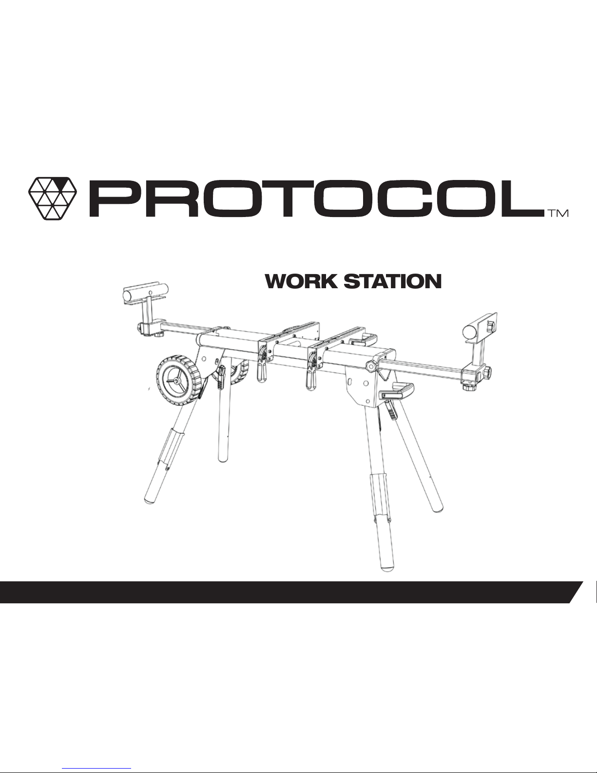
CONTRACTOR MITER SAW
WORK STATION
PRODUCT MANUAL
1
WS-077
Page 2
2
SAFETY WARNING
WARNING: Be sure to read and understand all safety instructions in this manual, including all safety alert symbols such as “DANGER”, “WARNING” and
“CAUTION”, before using this power tool accessory. Failure to follow all instructions listed in the manual may result in electric shock, re and/or serious
personal injury.
GENERAL SAFETY INSTRUCTIONS FOR POWER TOOLS
Using power tools of any kind can be dangerous if safe operation procedures are not followed. Recognizing the hazards of each tool and using them
with respect and caution will considerably limit the possibility of personal injury. However, if safety precautions are ignored, personal injury will likely
result. Always use common sense – your personal safety is your responsibility.
1. Know your power tool. Read and understand the Product Manual and observe the warnings and instruction labels afxed to the tool.
2. Properly ground all tools.
3. Keep guards in place.
4. Remove adjusting keys and wrenches.
5. Keep work area clean and dry.
6. Keep children away.
7. Never leave running machines/tools unattended.
8. Disconnect tools from service.
9. Use correct tools for the job.
10. Never force a tool.
11. Wear safety apparel.
12. Wear safety glasses/goggles.
OVERVIEW
You have just purchased a Contractor Work Station. This product has been specically designed to assist you in the use of your 10-12" miter saw, as
well as increasing efciency with other bench top tools such as table saws, band saws, planers, etc.
FIG 1
Page 3
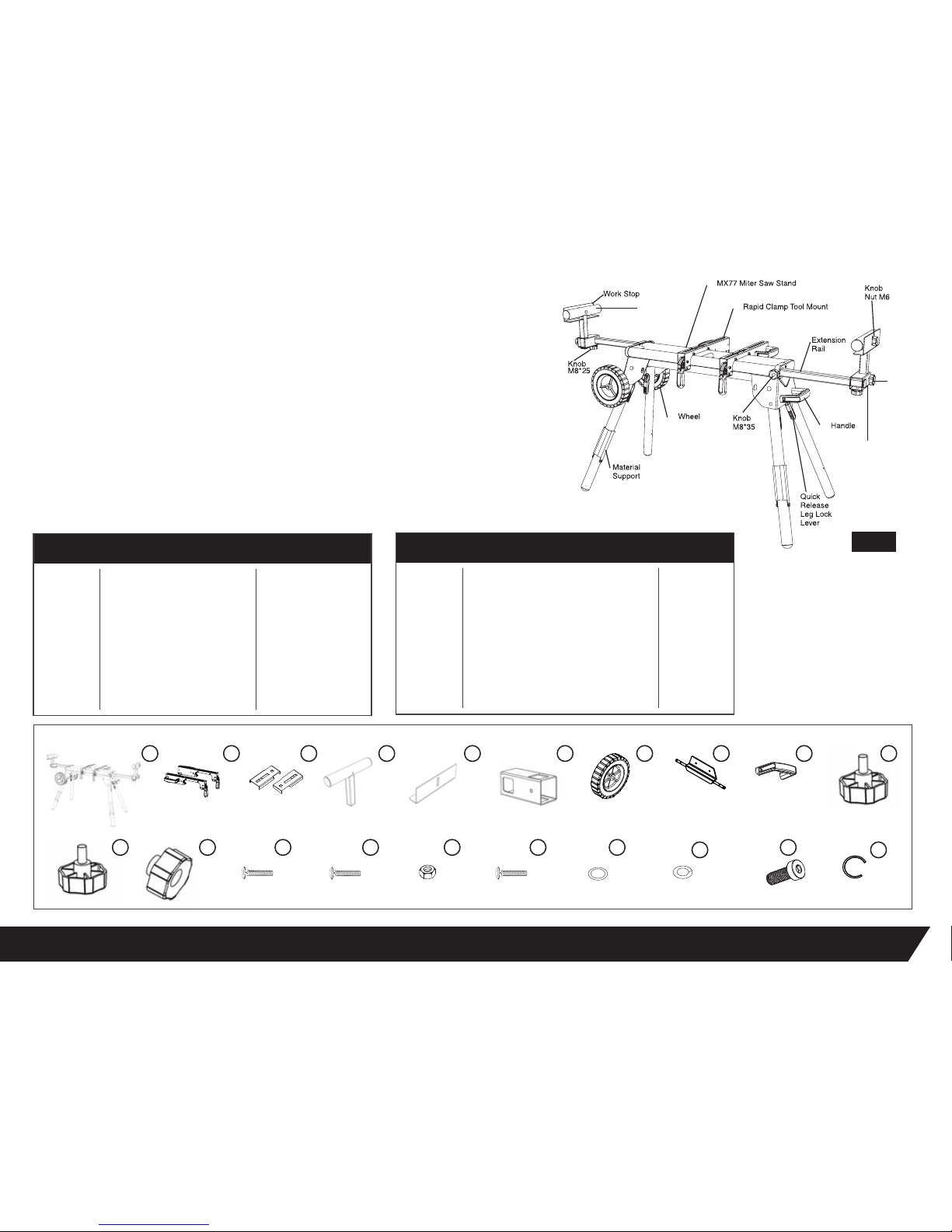
MITER SAW STAND
RAPID TOOL MOUNT CLAMP
MOUNT ADAPTER
MATERIAL SUPPORT
WORK STOP
MATERIAL SUPPORT RECEIVER
WHEEL
AXLE PLATE
HANDLE
KNOBS M8*35
1 pcs
2 pcs
2 pcs
2 pcs
2 pcs
2 pcs
2 pcs
1 pcs
1 pcs
2 pcs
DESCRIPTION QTYPART #
PARTS LIST
3
13. Never stand or sit on tools.
14. Replace damaged components immediately.
15. Make sure your work platform is sufciently sturdy to do the specic job at hand.
16. Think safety. Safety is a combination of operator awareness, common sense and
alertness at all times.
1
2
3
4
5
6
7
8
9
10
KNOBS M8*25
KNOB NUTS M6
CARRIAGE BOLT M8*55
CARRIAGE BOLT M8*20
NUT M8
CARRIAGE BOLT M8*60
WASHER #8
SPRING WASHER #8
BOLT M8*25
C-CLIP
2 pcs
2 pcs
2 pcs
2 pcs
12 pcs
4 pcs
12 pcs
12 pcs
4 pcs
4 pcs
DESCRIPTION QTYPART #
11
12
13
14
15
16
17
18
19
20
FIG 2
1 52 3 4 6 7 8
9
10
11
12
13 14 15 19
20
16
17
18
Material
Support
Material
Support
Receiver
Knob
M8*25
Page 4
SAFETY INSTRUCTIONS FOR MITER SAW STANDS
1. Use caution when folding or unfolding legs to limit any nger pinch points.
2. Place stand on at and level surface to keep from rocking or tipping.
3. Make sure that work support extensions (if included) are within safe operating limits, and
are properly locked in place before using tool. Do not exceed the rated capacity on main frame table.
4. Test the setup for stability before proceeding with work.
5. Be sure the miter saw is tightened securely at all mountings before folding the work station for transport.
4
FEATURES
Your Contractor Miter Saw Work Station is loaded with standard features all designed and
engineered to maximize the functionality and exibility of your Work Station.
STANDARD FEATURES
• Rapid Clamp Tool Mounts
• Adjustable Material Supports
• Wheels for for easy transportation
ASSEMBLY INSTRUCTIONS
Read all assembly instructions completely before attempting assembly.
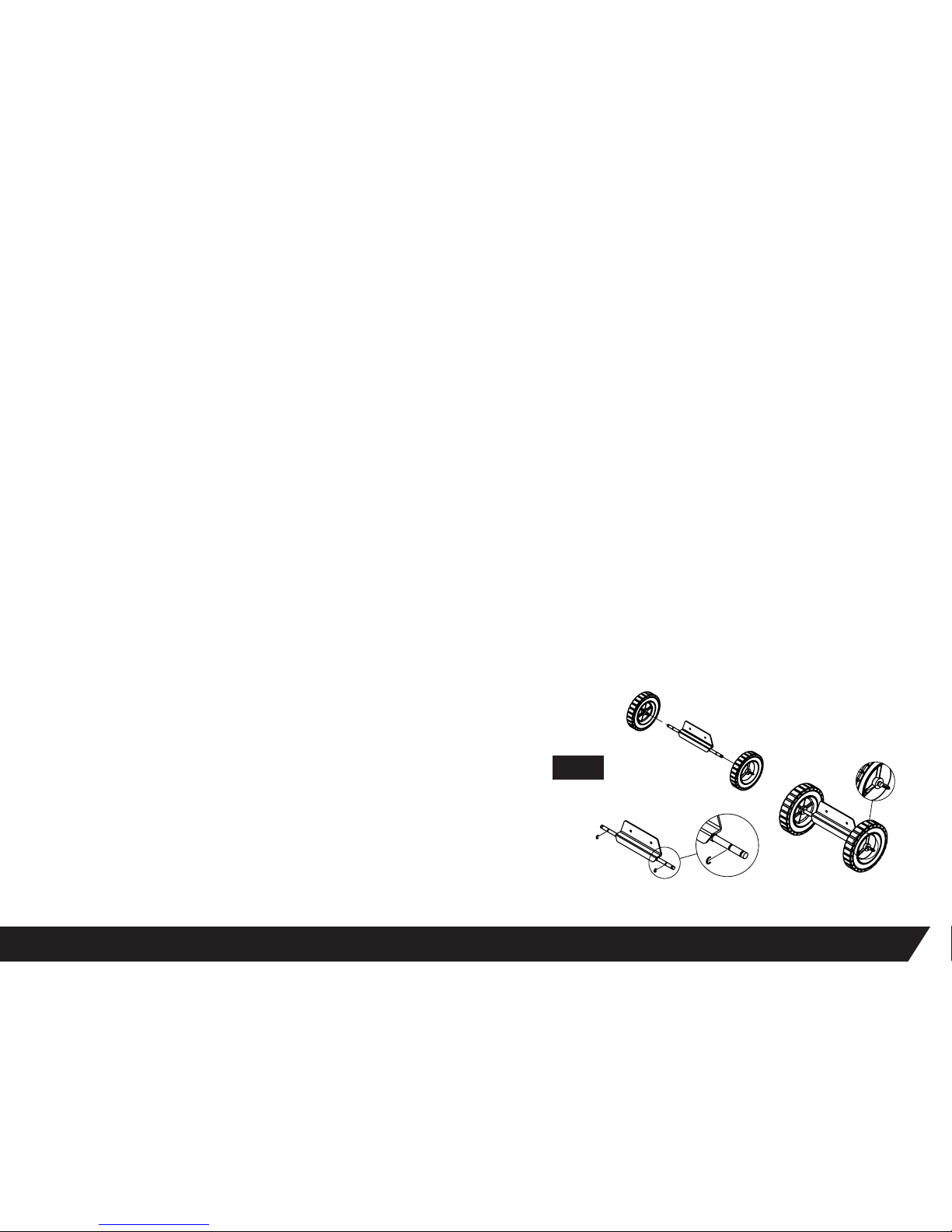
ATTACHING THE WHEELS
See Figure 3
1. Using pliers, squeeze a C-clip over the inner grove closest to the miter
saw stand.
2. Place the wheel onto the axle and secure it using another C-clip toward the
end of the axle.
3. The C-clips should snap into place and hold the wheel onto the axle.
Step 1
Step 2
Step 3
FIG 3
Page 5
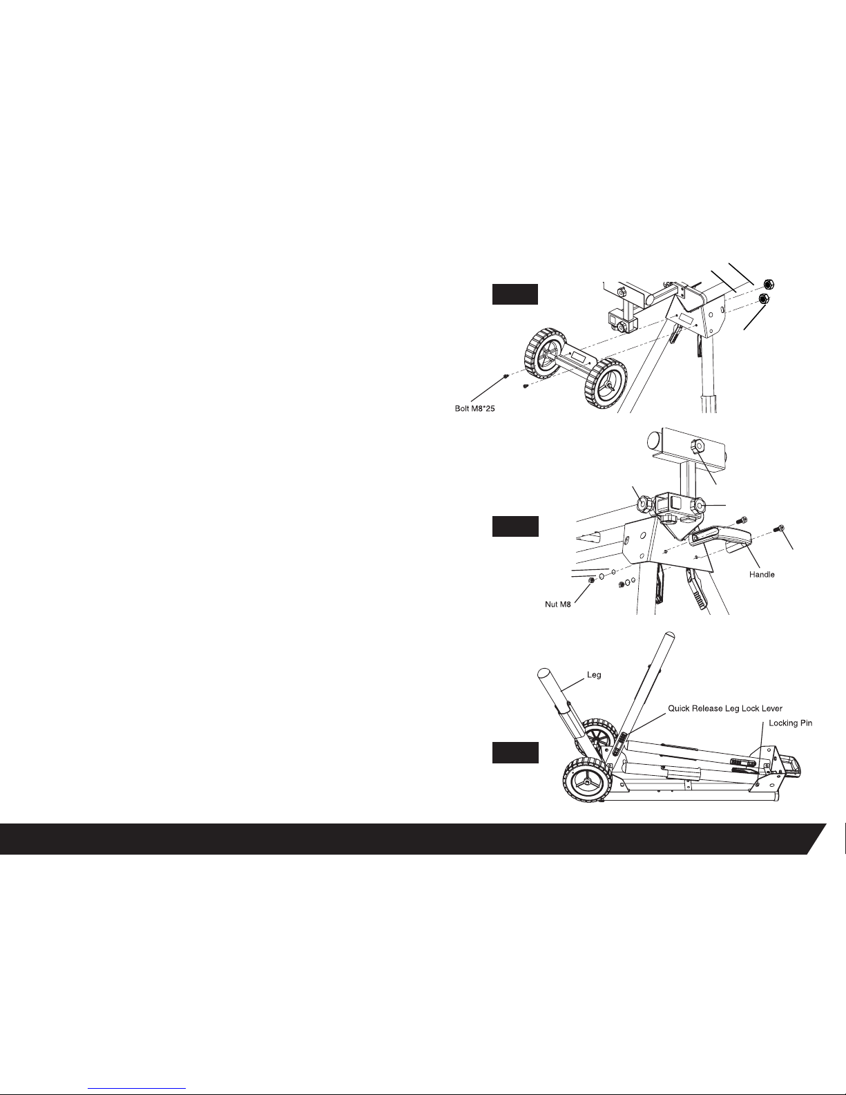
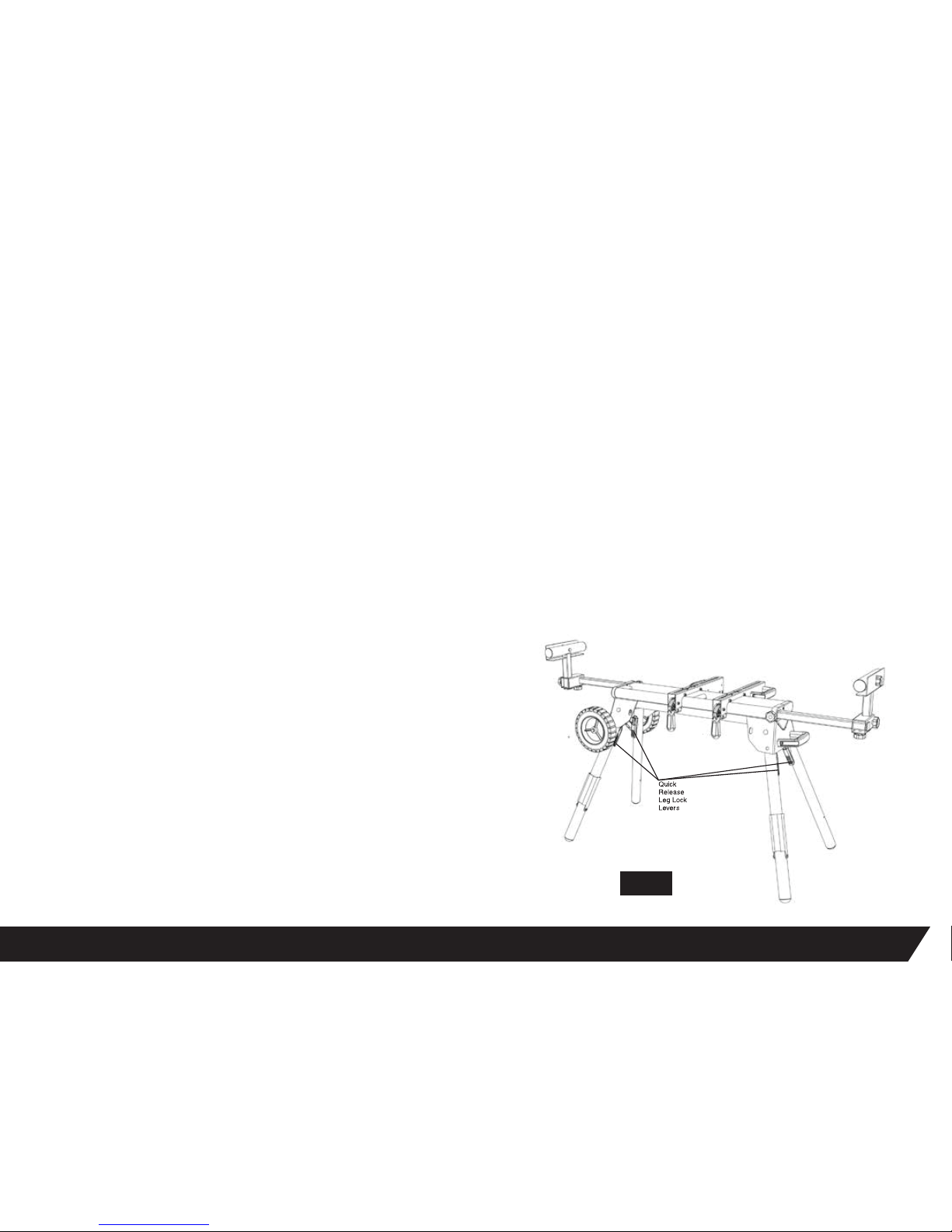
PREPARING THE STAND
See Figure 6
1. Lay the stand’s top surface down on the oor with the folded legs on top.
2. Press the Quick Release Leg Lock Lever and rotate that leg up until the locking pin
clicks into place.
3. Repeat with the remaining three legs.
4. Lift the stand and place it in an upright position.
5. Check to ensure the stand is stable and that all the legs have the locking pins engaged.
5
Washer
Spring Washer
Nut
ATTACHING THE AXLE PLATE
See Figure 4
1. Place (2) M8*20 bolts through the holes in the axle plate.
2. Place the axle plate onto the end of the miter saw stand making sure that the bolt
runs through the holes on the miter saw stand.
3. Place the washer and spring washer over each bolt on the back side of the miter
saw stand.
4. Lift the miter saw stand to an upright position.
5. Tighten M8 nut over the washer until secure.
ATTACHING THE PULL HANDLE
See Figure 5
1. Place (2) M8*20 bolts through the holes in the plastic handle.
2. Place the handle onto the end of the miter saw stand, and make sure the M8
bolts pass through the holes in the body.
3. Place a washer and spring washer over each bolt exposed on the backside of
the miter saw stand.
4. Lift the stand and place it in an upright position.
5. Tighten M8 nut over the washers until secure.
FIG 4
FIG 5
FIG 6
Spring Washer
Washer
Knob Nut M6
Bolt M8*20
Knob M8*25
Knob M8*35
Page 6
6
ATTACHING YOUR MITER SAW OR OTHER BENCH TOP POWER TOOL
See Figure 8
Various bench top tools can be used with your Contractor Miter Saw Work Station by attaching
them to the Rapid Clamp Tool Mounts. Always position the saw to achieve maximum balance and
stability. All four corners of the saw must be bolted to the tool mounts before use. Make sure
bolts do not extend above the table of the miter saw.
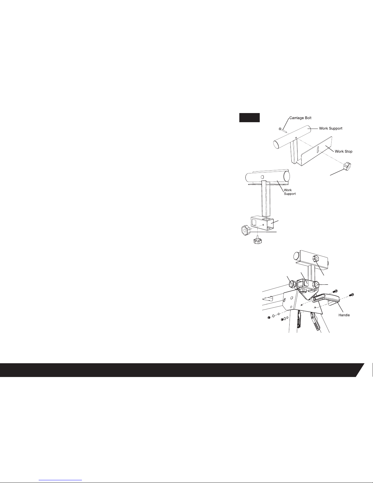
ASSEMBLING AND INSTALLING MATERIAL WORK SUPPORTS
See Figure 7
1. Slide a carriage bolt (M6 x 55mm) through the square hole in the work support and extend
through the other side.
2. Place the work stop over the end of the bolt.
3. Thread a knob nut M6 (Part #12) over the end of the bolt and tighten to secure.
4. Slide the work support rail through the hole in the top of the work support mounting bracket.
5. Insert knob M8*25 (Part #11) through the small hole on the side of the material support
receiver and tighten to secure.
6. Slide the material support receiver over the extension rail so that the extension rail extends
through the opening in the receiver. Position the work support at the desired location on the
extension rail.
7. Thread knob M8*35 (Part #10) into the hole in the bottom of the material support receiver and
tighten to secure.
8. There are two M8*35 knobs. They have slightly longer shafts than knobs M8*25. To use, insert
them into the crossbeams to adjust the length of the extension rail.
9. Repeat with the other supports.
FIG 7
Knob Nut M6
Material
Support
Receiver
Knob M8*25
Knob Nut M6
Knob M8*25
Knob M8*35
Extension Rail
Page 7
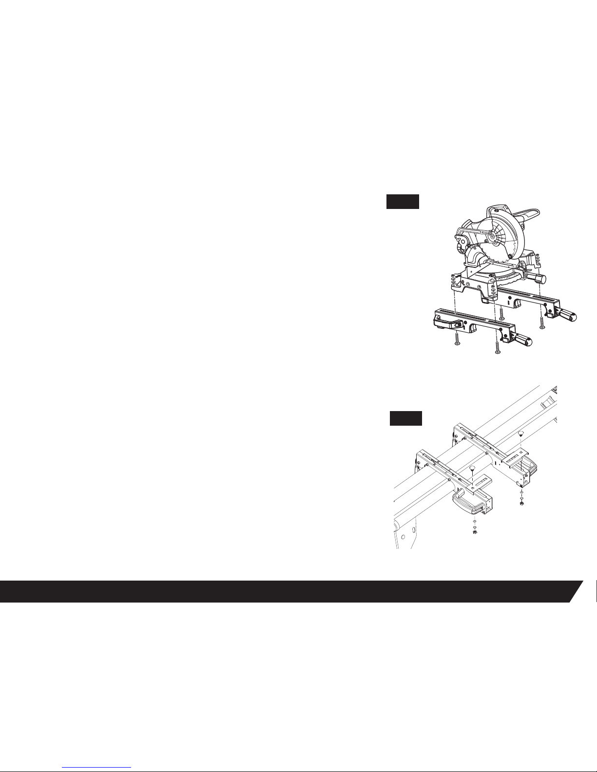
OFFSET MOUNTING
See Figure 9
Offset Mounting Bracket for Miter Saws and/or Power Tools with an irregular
mounting hole pattern.
Instructions: Secure offset mounting brackets as shown. Brackets can be used
on the front or rear of the Rapid Clamp Tool Mounts.
NOTE: If the saw has holes that do not line up with the slots in the tool
mounts, use the offset mounting brackets.
1. Unplug the saw and lock the saw arm in the down position.
2. Place a tool mount underneath the saw, aligning the mounting holes on the miter saw
base with the slot in the top of the tool mount.
3. Feed a carriage bolt up through both the tool mount and a mounting hole in the saw.
4. Secure in place using a at washer, spring washer, and nut.
5. Repeat through the other end of the tool mount.
6. Place the second tool mount underneath the other side of the saw, aligning the
mounting holes on the miter saw base with the opening in the tool mount.
7. Install carriage bolts as previously described.
8. After making sure both tool mounts are parallel to each other, nger tighten all four nuts
to hold in position.
FIG 8
FIG 9
7
Page 8
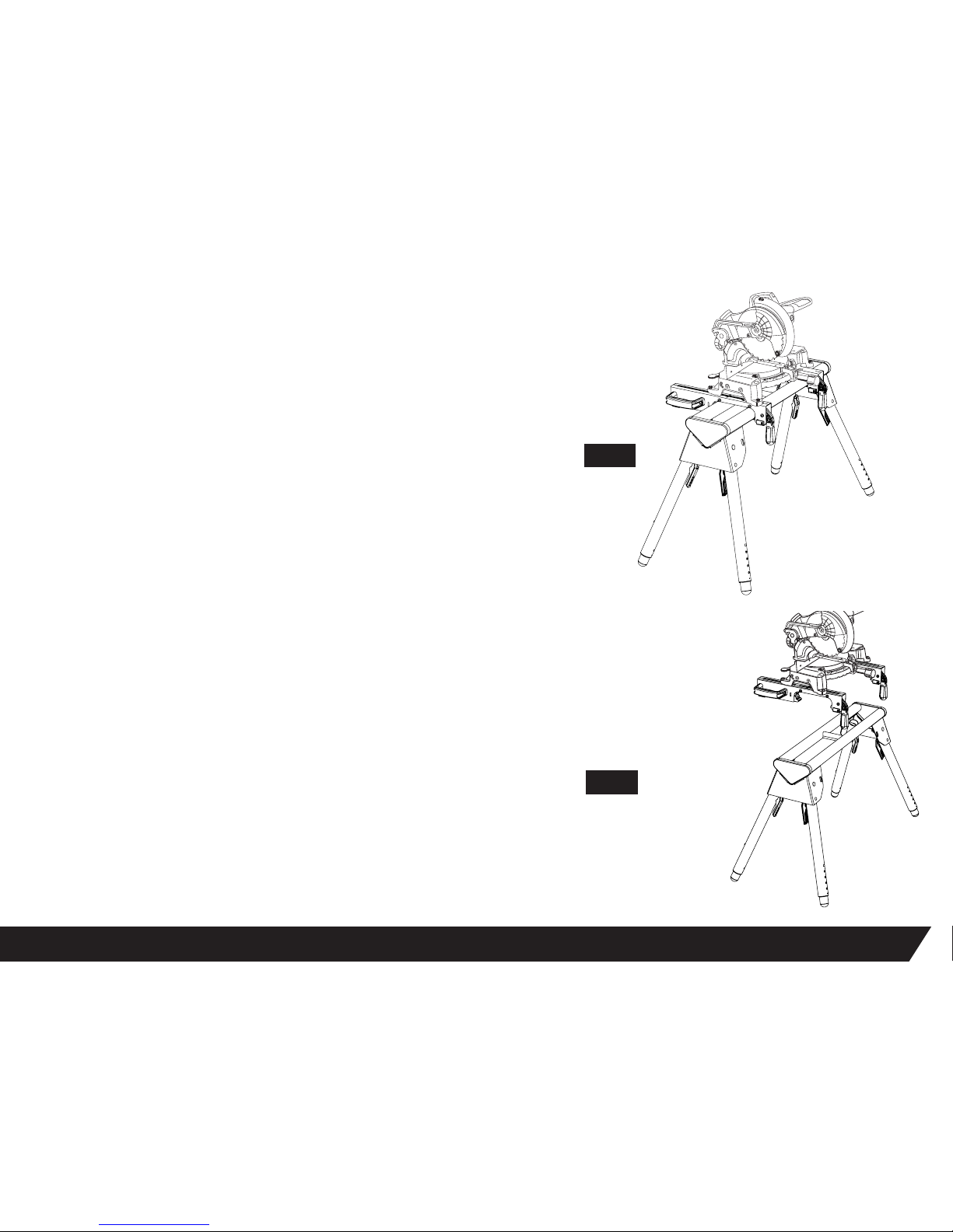
TO REMOVE SAW FROM STAND
See Figure 11
1. Raise the locking levers to unlock the saw and tool mounts.
2. Lift away from the rear rail of the stand to disengage.
3. With the assembly tilted slightly toward you, lift the assembly to disengage from
the front rail of the work station.
8
MOUNTING THE MITER SAW TO THE STAND
See Figure 10
Use the handles located at the rear of the tool mounts to aid in installing or
removing saw and tool mount assembly.
1. Lift the saw and tool mount assembly, allowing the assembly to tilt slightly
toward your body.
2. While still tilted toward you, hook the front edge of the tool mount assembly
onto the front rail of the stand.
3. Lower the tool mount assembly to allow the rear edge of the tool mount to seat
fully over the rear rail.
4. Lock the tool mounts in position by lowering the locking levers.
NOTE: Continue to hold the tool mount assembly with one hand until both
levers are securely locked.
5. Check position and adjust if necessary to make sure the weight of the saw is evenly
balanced over the rails.
6. Ensure the saw is seated and locked in position, then securely tighten the four nuts
holding the saw to the tool mounts.
FIG 11
FIG 10
Page 9
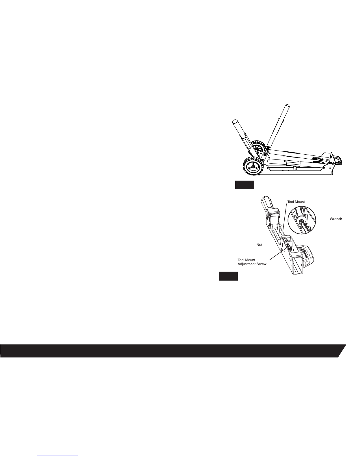
TRANSPORTING AND STORING
See Figure 12
1. Before storing or transporting, make sure all attachments are secure and bench top tool
is removed.
2. Collapse legs and make sure they are locked into the up position.
3. Use the handle that is located on the end of the product for transporting.
4. Pull up on the handle and tilt workstation until weight is distributed evenly onto wheels.
TOOL MOUNT ADJUSTMENT SCREW
Most plastic tool mounts are designed to t snugly over the stand rails. With the locking levers
in the lowered (locked) position, you should not be able to remove the saw and tool mount
assembly from the rails. If the saw and tool mount can be removed from the rails when the
levers are locked, the tool mount adjustment screws need to be tightened. If the saw and the
tool mount assembly will not t over both rails, the bracket adjustment screws needs to
be loosened.
NOTE: The saw should be removed from the tool mounts before attempting to
tighten or loosen the tool mount adjustment screws.
9
TO ADJUST
See Figure 13
1. Use a wrench to slightly loosen the nut.
2. Turn the screw with a Phillips screwdriver. Rotate clockwise if the tool mount assembly needs to be tightened or counterclockwise if the assembly
needs to be loosened.
3. Install the tool mount on the Contractor Miter Saw Work Station rails and lower the locking lever to check the adjustment.
4. When the correct position is achieved, tighten the nut with a 10mm open-ended wrench to secure.
5. Repeat steps 1 through 4 to attach the second tool mount.
FIG 12
FIG 13
Page 10
10
LIFETIME
LIMITED
WARRANTY
PROTOCOL
™
Contractor Miter Saw Work Station is
backed by a Limited Lifetime Warranty.
This warranty covers manufacturer defects and workmanship. The warranty excludes misuse or
abuse and normal wear and tear. Exclusion is not allowed in some states and may not apply.
This warranty gives you specific legal rights, and you may have other rights, which vary from
state to state.
JS PRODUCTS 6445 MONTESSOURI STREET LAS VEGAS, NV 89113
800.255.7011 | FAX: 775.898.8773 | FOR MORE PRODUCTS AND ACCESSORIES GO TO WWW.PROTOCOLEQUIPMENT.COM
GENERAL MAINTENANCE
Avoid using solvents when cleaning plastic parts. Most plastics are susceptible to damage from various types of commercial solvents and may be
damaged by their use. Use clean cloths to remove dirt, dust, oil, grease, etc.
|
|
 Loading...