

Page 1

J138WP-M and J150WP-M
Operation and Maintenance Manual
To reduce the risk of injury, read and understand these safety
warnings and instructions before using the tool. Keep these
instructions with the tool for future reference. If you have any
questions, contact your PROTO® representative or distributor.
WARNING
3/8" Mini Air Impact Wrench
1/2" Mini Air Impact Wrench
1/2" J150WP-M
3/8" J138WP-M
© 2015 PROTO
Page 2
2
INTRODUCTION
The PROTO® J138WP-M and J150WP-M are precision-built tools, designed for professionals for high torque assembly
and disassembly of threaded fasteners. These tools will deliver efficient, dependable service when used correctly and
with care. As with any fine power tool, for best performance the manufacturer’s instructions must be followed. Please
study this manual before operating the tool and understand the safety warnings and instructions. The instructions on
installation, operation and maintenance should be read carefully, and the manuals kept for reference. NOTE: Additional
safety measures may be required because of your particular application of the tool. Contact your PROTO® Distributor with
any questions concerning the tool and its use.
PROTO INDUSTRIAL TOOLS
2195 East View Parkway
Suite 103
Conyers, Georgia 30013
Phone: +1 800-800-TOOL
Fax: +1 770-648-9108
www.protoindustrial.com
TABLE OF CONTENTS
Introduction 2
Safety Instructions 3
Specifications 4
Getting Started 5
Tool Components 6, 7
Contact Information 8
WARNING
IMPORTANT SAFETY INFORMATION ENCLOSED.
READ THIS MANUAL BEFORE OPERATING THE MACHINE.
SAVE FOR FUTURE REFERENCE
FAILURE TO OBSERVE THE FOLLOWING WARNINGS COULD RESULT IN INJURY.
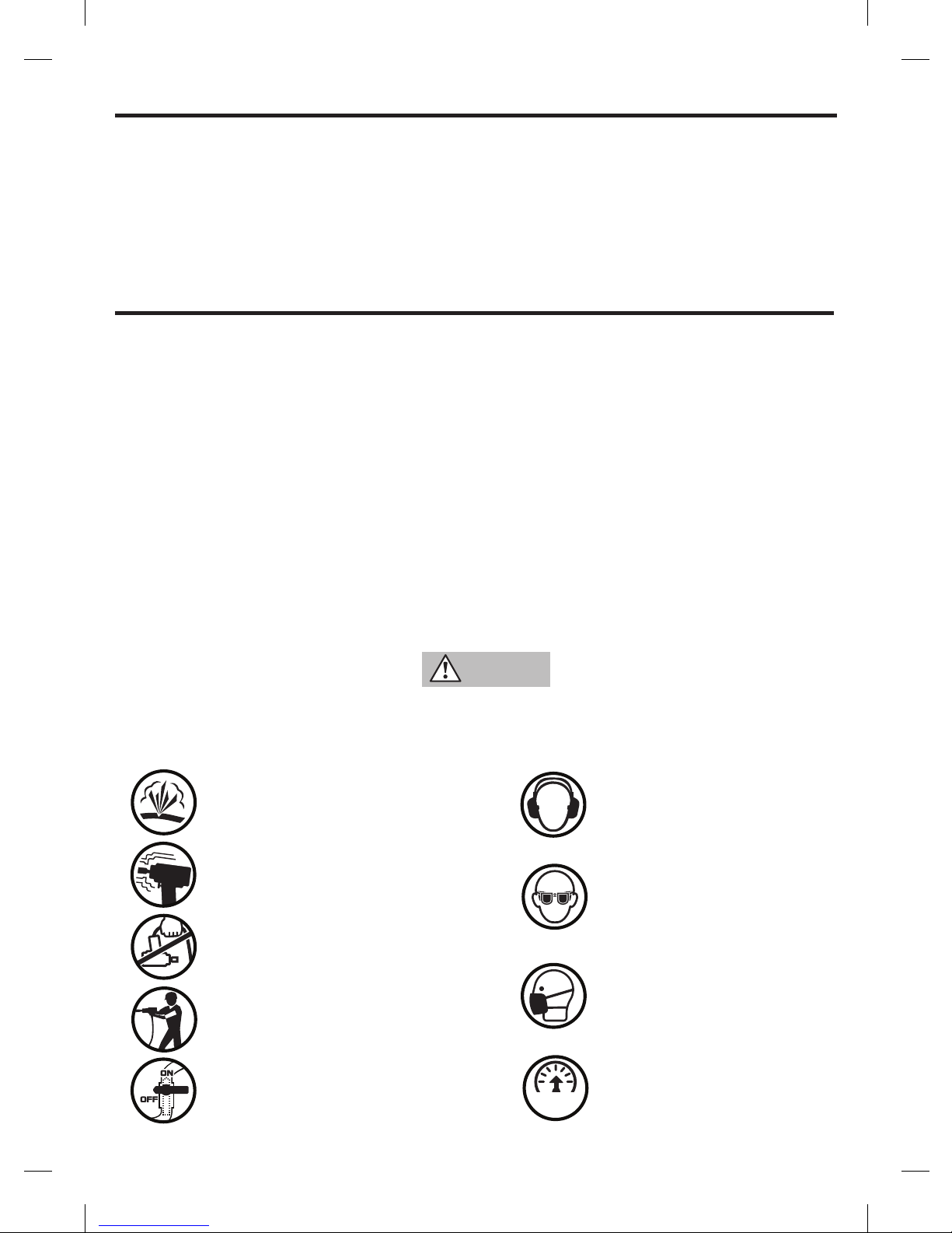
Do not use damaged, frayed or deteriorated air hoses
and fittings.
Air powered tools can vibrate in use. Vibration, repetitive
motions or uncomfortable positions may be harmful to
your hands and arms. Stop using any tool if discomfort,
tingling feeling or pain occurs. Seek medical advice before
resuming use.
Do not carry the tool by the hose.
Keep body stance balanced and firm. Do not overreach
when operating this tool.
Always turn off the air supply and disconnect the air
supply hose before installing, removing or adjusting any
accessory on this tool, or before performing any maintenance on this tool.
Always wear hearing protection when operating
this tool.
Always wear eye protection when operating or
performing maintenance on this tool.
Always wear respiratory protection when operating
this tool.
Operate at 90 psig (6.2 bar / 620 kPa) Maximum
air pressure.
6.2 bars
(90 psig/
620 kPa)
6.2 bars
(90 psig/
620 kPa)
6.2 bars
(90 psig/
620 kPa)
6.2 bars
(90 psig/
620 kPa)
6.2 bars
(90 psig/
620 kPa)
6.2 bars
(90 psig/
620 kPa)
Page 3

3
GENERAL SAFETY INSTRUCTIONS
Keep away from children
Always wear ANSI Z87.1 eye protection when operating or performing maintenance on this tool. Everyday eye glasses
are not safety glasses
Always wear hearing protection when operating this tool
Keep hands, loose clothing and long hair away from rotating end of tool
Anticipate and be alert for sudden changes in motion during start up and operation of any power tool
Keep body stance balanced and firm. Do not overreach when operating this tool
Use clamps or another practical way to secure and support the workpiece to a stable platform. Holding the work by
hand or against the body is unstable and can lead to loss of control
Do not operate this tool for long periods of time. Vibration caused by tool action may be harmful to your hands and
arms. Stop using any tool if discomfort, tingling feeling or pain occurs. Seek medical advice before resuming use
Stay alert. Do not use the tool while tired or under the influence of drugs, alcohol, or medication
Use only impact accessories. Non-impact accessories may break and cause a hazardous condition. Inspect accesso-
ries prior to use to ensure that it con tains no cracks.
Do not operate this tool in the presence of flammable liquids, gasses, dust, or explosive atmospheres
This tool is not insulated against electric shock, contact with a live wire will make exposed metal parts live
Always turn off the air supply and disconnect the air supply hose before installing, removing or adjusting any acces-
sory on this tool, or before performing any maintenance on this tool
Avoid unintentional starting. Be sure trigger is off before connecting to the air supply
For safety, top performance, and maximum durability of parts, operate this tool at 90 psig (6.2 bar / 620 kPa)
maximum air pressure at the inlet with 3/8’’ (10mm) inside diameter air supply hose. Adequate air supply volume
is required for full power. Restrictions in the supply and volume will cause a drop in air pressure when the trigger is
pulled resulting in lower power
Do not use damaged, frayed or deteriorated air hoses and fittings
Do not lubricate tools with flammable or volatile liquids such as kerosene, diesel or jet fuel
Do not remove any labels. Replace any damaged label
Tool service must be performed by qualified repair personnel. When servicing, use only PROTO® authorized, identical
replacement parts. Use only lubricants recommended by PROTO
®
Do not use this tool at heights exceeding 6 feet (2m)
Some dust created by power sanding, sawing, grinding, drilling, and other construction activities contains chemicals
known to the State of California to cause cancer, birth defects or other reproductive harm.
Some examples of these chemicals are:
- lead from lead-based paints
- crystalline silica from bricks and cement and other masonry products
- arsenic and chromium from chemically-treated lumber
Your risk from these exposures varies, depending on how often you do this type of work. To reduce your exposure to
these chemicals: work in a well ventilated area, and work with approved safety equipment, such as those dust masks
that are specially designed to filter out microscopic particles
Do not use the tool if the trigger does not turn the tool on or off
Accessories and tools get hot during operation. Wear gloves when touching them
Inspect anvils and hog rings prior to use. Missing or damaged items should be replaced before use
Page 4
4
1/4” NPT
HIGH FLOW
FITTING
AIR HOSE
3/8” (10 mm)
I.D. MIN.
COMPACT
Refer to chart below
for size
SPECIFICATIONS
HIGH TORQUE
Refer to chart below for
breakaway torque specs
SPECIFICATIONS
Model #
Square
Drive
Blow
Rate
Breakaway
Torque
Noise Level Vibration Level
in bpm ft-lbs / Nm Pressure dB(A) Power dB(A) Pressure dB(C) m/s
2
J138WP-M 3/8 1260 445 / 603 93.2 3 104.2 3 <130 3 7.78 1.27
J150WP-M 1/2 1650 635 / 861 97.1 3 108.1 3 <130 3 9.57 1.44
Model #
Free
Speed
Average Air
Consumption
Working
Pressure
Weight Dimensions
rpm cfm / l/min psi / bar lbs / kg in / mm
J138WP-M 6,000 3 / 85 90 / 6.2 2.8 / 1.3 4.4 x 2.4 x 6.8 / 111 x 61.5 x 173
J150WP-M 10,000 4.5 / 127 90 / 6.2 2.8 / 1.3 4.4 x 2.4 x 6.8 / 111 x 61.5 x 173
* = measurement uncertainty in dB(A) ** = measurement uncertainty in m/s²
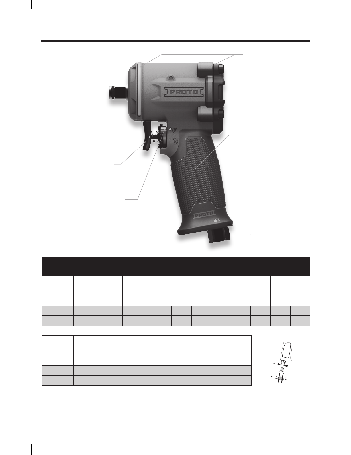
VARIABLE SPEED TRIGGER
For maximum speed control
ONE-HAND FORWARD/REVERSE
SWITCH
Integrated 3-position
regulator for power control and
ease of use
RUBBER BUMPERS
Protect the tool
from damage
COMFORT GRIP
Rubber injected overlay,
resistant to oils and acids
Page 5
5
GETTING STARTED
Always operate, inspect and maintain this tool in accordance with all regulations (local, state, federal and country) that may apply to
hand-held / hand-operated pneumatic tools
For maximum performance, the air coupler on the wall should be the next size larger than the air coupler used on the tool. The coupler
closest to the tool should not be smaller than the proper air supply hose size
Be sure all hoses and fittings are the correct size and are tightly secured
Always use clean, dry air at 90 psig maximum air pressure. Dust, corrosive fumes and/or excessive moisture can ruin the motor of an
air tool
Inject the tool every 100-200 cycles with 1-3 grams of grease. Applications vary and grease may need to be applied more in colder
climates/conditions and less in hotter climates/conditions. The grease that should be used should be Petroleum or Synthetic, NLGI
Grade 2, -4/2300 F(-20/1100 C). The tool has a 1/8” Flush type grease fitting. If lower performance is observed immediately after
adding grease, service is needed to remove the build-up within the clutch housing
The use of a hose whip is recommended. A coupler connected directly to the air inlet increases tool bulk and decreases tool
maneuverability
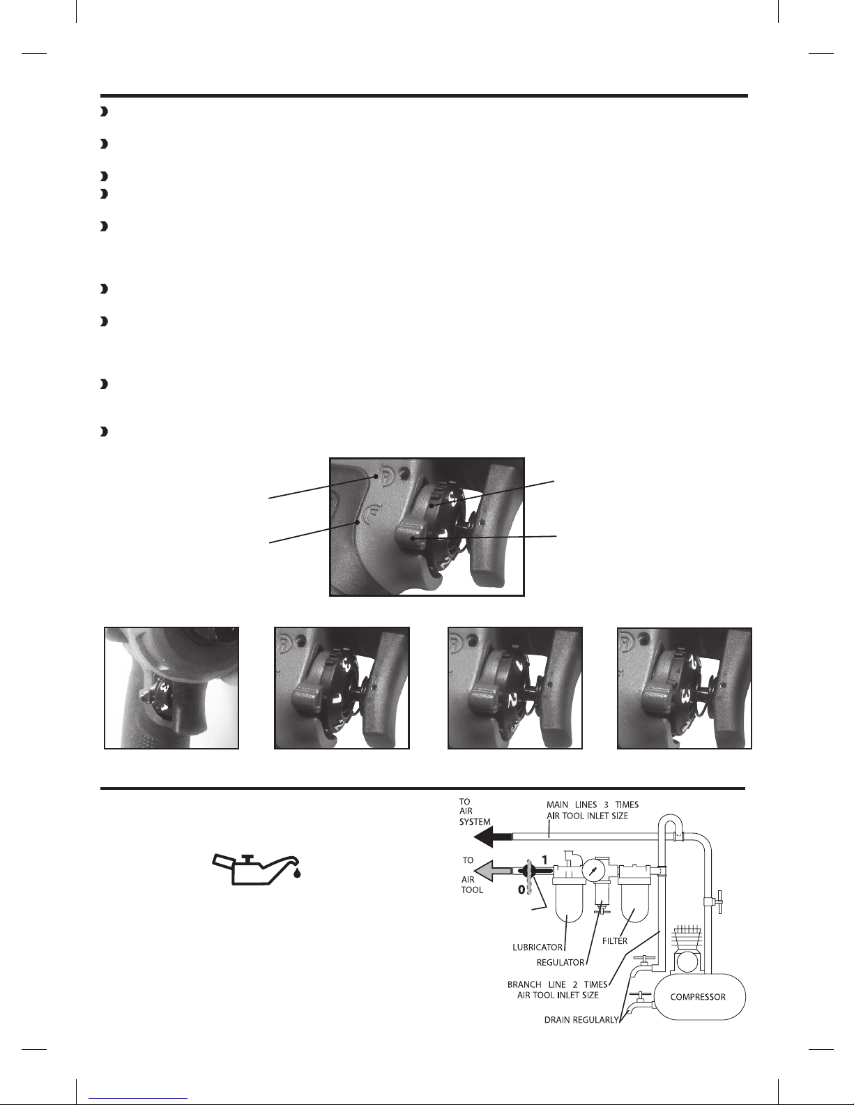
The regulator has 3 power positions, position 1 is the lowest and 3 is full power. To set the tool power with the regulator, turn the
dial until the power setting represented by 1, 2 or 3 is under the lever in the forward position as shown in Figure A. When the reverse
setting is selected the tool will operate, in reverse, at full power regardless of the power setting that is chosen. The F on the handle
represents forward and the R represents reverse
The Forward / Reverse Lever must be fully engaged in either the forward or reverse position to ensure the tool works with maximum
performance. If the Forward / Reverse Lever is positioned in the middle (see example below, bottom left picture) between forward and
reverse, the tool will not be as efficient and powerful
Use Hi-Flow air fittings and couplers for maximum tool performance
Figure A
Not Engaged - No Power
Power Setting 3 (Max)
Power Setting 2Power Setting - 1 (Low)
FORWARD/REVERSE LEVER
REVERSE POSITION
FORWARD POSITION
POWER SETTING
EMERGENCY
GATE VALVE
PLACING TOOL IN SERVICE
LUBRICATION
Always use an air line lubricator with this tool. After every eight
hours of operation, if a lubricator is not used on the compressed
air network, inject 1/2 to 1cm3 of approved air tool oil through the
machine’s inlet connection.
Page 6
6
410
411
L
401
413
202
104A*
L __
104*
417*
420
I
105*
418
*
(*) Wearing Parts
A
306
305
I Jl38-KI
102A*
103A*
Page 7

7
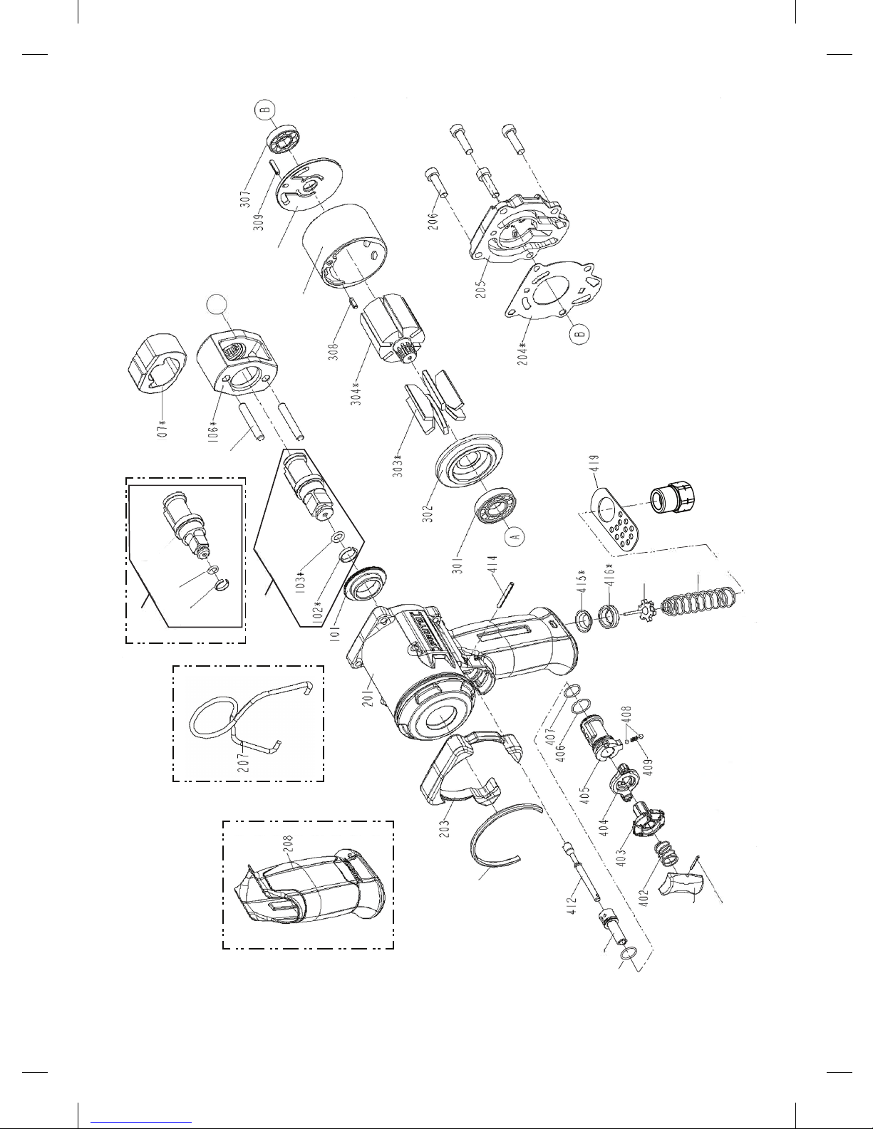
All parts available through www.servicenet.protoindustrial.com
ITEM # PART # DESCRIPTION QTY
101 N449222 HAMMER CASE BUSHING 1
104 N449227 1/2" ANVIL ASSEMBLY 1
102 N449223 1/2" SOCKET RETAINER RING 1
103 N449225 1/2" O-RING 1
104A N449228 3/8" ANVIL ASSEMBLY 1
102 N449224 3/8" SOCKET RETAINER RING 1
103 N449226 3/8" O-RING 1
105 N449229 HAMMER PIN 2
106 N449230 HAMMER FRAME 1
107 N449231 HAMMER 1
201 N449269 3/8" HOUSING 1
201 N449270 1/2" HOUSING 1
202 N449283 FRONT BUMPER 1
203 N449285 REAR BUMPER 1
204 N449286 GASKET (PACKING)-MOTOR 1
205 N449287 REAR COVER PLATE 1
206 N449288 HEX.SOC.HD.BOLT 4
207 N449289 HANGER 1
208 N449292 GRIP 1
301 N449293 BEARING 1
302 N449298 FRONT BEARING PLATE 1
303 N449299 ROTOR BLADES 6
304 N449300 ROTOR 1
ITEM # PART # DESCRIPTION QTY
305 N449301 CYLINDER 1
306 N449302 REAR END PLATE 1
307 N449303 BEARING 1
308 N449304 SPRING PIN 1
309 N449305 SPRING PIN 1
401 N449296 TRIGGER 1
402 N449297 SPRING 1
403 N449306 REGULATOR A 1
404 N449307 LEVER 1
405 N449315 REVERSE VALVE 1
406 N449316 O-RING 1
407 N449317 O-RING 1
408 N449318 BALL-DETENT 2
409 N449319 POSITIONING SPRING 1
410 N449320 O-RING 1
411 N449321 REGULATOR B 1
412 N449322 TRIGGER PIN-TIP VALVE 1
413 N449323 SPRING PIN 1
414 N449324 SPRING PIN 1
415 N449325 BUSHING-TIP VALVE 1
416 N449326 SEAL-TIP VALVE 1
417 N449327 TIP VALVE 1
418 N449328 SPRING 1
419 N449330 EXHAUST DEFLECTOR 1
420 N449332 AIR INLET 1
Page 8

8
CUSTOMER SERVICE
We at PROTO are committed to our customers, please reference the following phone number for a direct contact to one of our
customer technicians. They will be more than happy to help with any service or warranty questions you may have about your power tool.
PROTO INDUSTRIAL TOOLS
2195 East View Parkway
Suite 103
Conyers, Georgia 30013
Phone: +1 800-800-TOOL
Fax: +1 770-648-9108
www.protoindustrial.com
CE DECLARATION OF CONFORMITY
WE, PROTO INDUSTRIAL TOOLS, 2195 EAST VIEW PARKWAY, SUITE 103, CONYERS, GEORGIA 30013, DECLARE UNDER OUR SOLE
RESPONSIBILITY THAT THE PRODUCTS J138WP-M 3/8” MINI AIR IMPACT WRENCH AND J150WP-M 1/2” MINI AIR IMPACT WRENCH
- CONFORM WITH THE DIRECTIVE AND STANDARDS "MACHINERY" DIRECTIVE 2006/42/CE
- AND ARE IN CONFORMITY WITH THE PROVISIONS OF THE HARMONISED EUROPEAN STANDARD
EN ISO 12100:2010
EN ISO 11148-6:2012
EN ISO 15744:2008
EN ISO 28927-2:2009
KEVIN LIN
QUALITY MANAGER
09.23.2015
Manual #N455497
J138WP-M and J150WP-M
Operation and Maintenance Manual
WARRANTY
We warrant that this tool shall be free from manufacturing defects for a period of TWO YEARS from the original purchase date. Our
obligation to the original purchaser shall be limited to repairing or replacing, at our expense (not including shipping charges) a defective
tool if returned by the original purchaser within two years from the date of purchase, all incoming shipping charges prepaid. THIS
WARRANTY DOES NOT COVER DEFECTS OR DAMAGES TO THE TOOL (i) after the warranty period expires; (ii) resulting from misuse or
abnormal operation; (iii) resulting from a failure to properly lubricate, maintain or operate the tool; or (iv) resulting from any repair or
maintenance services performed by any party other than PROTO® at all PROTO® Service Centers or a person authorized by PROTO® to
provide repair and maintenance services for this tool.
Page 9

Petite clé à chocs 3/8 po
Petite clé à chocs 1/2 po
J138WP-M et J150WP-M
Guide d’utilisation et de maintenance
Pour réduire tout risque de dommages corporels, lire et comprendre
ces consignes de sécurité et directives avant toute utilisation de
l’outil. Conserver ces instructions avec l’outil pour toute future
référence. Si vous avez des questions, veuillez contacter un
représentant PROTOMD ou l’un de ses distributeurs.
AVERTISSEMENT
1/2" J150WP-M
3/8" J138WP-M
© 2015 PROTO
Page 10

10
INTRODUCTION
Les modèles J138WP-M et J150WP-M PROTOMD sont des outils conçus pour les professionnels pour le montage ou le démontage à fort
couple de fixations filetés. Ces outils resteront fiables et efficaces dans la mesure où ils seront utilisés correctement et respectés. Comme
pour tout outil électrique de précision, pour des performances optimales, suivez les instructions du fabricant. Veuillez étudier ce guide
d’utilisation avant toute utilisation de l’outil et en comprendre les consignes de sécurité et les directives. Les instructions d’installation,
d’utilisation et de maintenance doivent être lues attentivement, et les guides d’utilisation conservés pour référence. REMARQUE : des
mesures de sécurité additionnelles pourront être requises pour une utilisation particulière de l’outil. Pour toute question relative à cet
outil et à son utilisation, veuillez contacter votre distributeur PROTOMD.
PROTO INDUSTRIAL TOOLS
2195 East View Parkway
Suite 103
Conyers, Georgia 30013
Téléphone : +1 800-800-TOOL
Télécopie : +1 770-648-9108
www.protoindustrial.com
TABLE DES MATIÈRES
Introduction 10
Consignes de sécurité 11
Caractéristiques techniques 12
Instructions de démarrage 13
Description de l’outil 14, 15
Coordonnées 16
AVERTISSEMENT
CONSIGNES DE SÉCURITÉ IMPORTANTES CI-INCLUSES. LIRE CE GUIDE
D’UTILISATION AVANT TOUTE UTILISATION DE L’OUTIL.
CONSERVEZ POUR RÉFÉRENCE FUTURE
RISQUES DE DOMMAGES CORPORELS EN CAS DE NON-RESPECT DE CES DIRECTIVES.
Ne pas utiliser de tuyaux ou raccords endommagés, détériorés
ou fissurés.
Les outils à air comprimé peuvent vibrer pendant leur
utilisation. Les vibrations, actions répétitives ou positions
inconfortables peuvent être nocives pour les bras et les mains.
Discontinuer l’utilisation de l’outil en cas d’inconfort, de
picotements ou de douleurs. Consulter un médecin avant d’en
reprendre l’utilisation.
Ne pas transporter l’outil par son tuyau à air.
Maintenir une posture équilibrée et ferme. Ne pas effectuer de
travaux hors de portée avec cet outil.
Arrêter l’arrivée d’air et déconnecter le tuyau d’air comprimé
avant d’installer,de retirer ou d'ajuster tout accessoire sur cet
outil, ou avant d’effectuer toute maintenance sur l’outil.
Porter systématiquement une protection auditive
pendant l’utilisation de cet outil.
Arrêter l’arrivée d’air et déconnecter le tuyau d’air
comprimé avant d’installer,de retirer ou d'ajuster
tout accessoire sur cet outil, ou avant d’effectuer
toute maintenance sur l’outil.
Porter systématiquement une protection oculaire
pendant l’utilisation de cet outil ou sa maintenance.
Utiliser à une pression d’air maximum de 6,2
bars/620 kPa (90 psi).
6.2 bars
(90 psig/
620 kPa)
6.2 bars
(90 psig/
620 kPa)
6.2 bars
(90 psig/
620 kPa)
6.2 bars
(90 psig/
620 kPa)
6.2 bars
(90 psig/
620 kPa)
6.2 bars
(90 psig/
620 kPa)
Page 11

11
CONSIGNES DE SÉCURITÉ GÉNÉRALES
AVERTISSEMENT
Ne pas laisser à la portée des enfants
Porter systématiquement une protection oculaire ANSI Z87.1 pendant l’utilisation de cet outil ou sa maintenance. Les
lunettes courantes ne sont pas des lunettes de protection
Porter systématiquement une protection auditive pendant l’utilisation de cet outil
Protéger les mains, les vêtements amples et les cheveux longs de toute extrémité rotative de l’outil
Anticiper et être prêt à tout changement soudain de course lors du démarrage et du fonctionnement de tous les outils
électriques
Maintenir une posture équilibrée et ferme. Ne pas effectuer de travaux hors de portée avec cet outil
Sécurisez et fixez la pièce à travailler sur une surface stable à l'aide d'un serre-joint ou de tout autre outil. Il est dé-
conseillé de tenir la pièce à la main ou contre le corps pour des raisons d'instabilité, pouvant aller jusqu'à une perte
de contrôle
Ne pas utiliser cet outil de façon prolongée. Les vibrations causées par l’outil peuvent être nocives pour les mains ou
les bras. Discontinuer l’utilisation de l’outil en cas d’inconfort, de picotements ou de douleurs. Consulter un médecin
avant d’en reprendre l’utilisation
Restez vigilant. N'utilisez pas l'outil lorsque vous êtes épuisé ou que vous avez consommé de la drogue, de l'alcool ou
des médicaments
Utiliser exclusivement des accessoires à percussion. Tout autre type d’accessoires pourrait se briser et poser des
risques sérieux. Avant toute utilisation, vérifier qu’ils ne comportent aucune fissure
Ne pas utiliser cet outil en présence de poussières, gaz ou liquides inflammables ou en milieu déflagrant
Cet outil n’est pas isolé contre les décharges électriques
, le contact avec un fil sous tension engendre également la
mise sous tension des surfaces métalliques
Arrêter l’arrivée d’air et déconnecter le tuyau d’air comprimé avant d’installer, de retirer ou d'ajuster tout accessoire
sur cet outil, ou avant d’effectuer toute maintenance sur l’outil
Évitez une mise en marche non intentionnelle. Assurez-vous que la détente est en position d'arrêt avant de le
brancher à l'alimentation d'air
Pour votre sécurité, des performances optimales et une durée de vie maximale des pièces, utiliser cet outil à une
pression d’air maximum de 6,2 bars/620 kPa (90 psi) à l’arrivée d’un tuyau à air de 19 mm (3/4 po) de diamètre
interne. Pour garantir une puissance maximale, une alimentation d'air suffisante est requise. Une alimentation et
un volume insuffisants vont provoquer une chute de la pression d'air, et donc une puissance réduite, au moment
d'enfoncer la gâchette
Ne pas utiliser de tuyaux ou raccords endommagés, détériorés ou fissurés
Ne pas lubrifier les outils avec des liquides inflammables ou volatils tels que kérosène, diesel ou carburéacteur
Ne retirer aucune étiquette. Remplacer toute étiquette endommagée
La maintenance de l'outil doit être effectuée par un technicien d'entretien qualifié. Durant la maintenance, n'utilisez
que des pièces de rechange identiques autorisées par
Proto
MD
. N'utilisez que des lubrifiants recommandés par Proto
MD
N'utilisez pas cet outil à plus de 2 m (6 pi)
La poussière engendrée par les travaux de ponçage, sciage, meulage, fraisage et autres activités liées à la
construction contient des substances chimiques reconnues par l’état de Californie comme pouvant causer le
cancer, des malformations congénitales ou autres dommages aux organes reproducteurs. Exemples de substances
chimiques :
- plomb provenant de peintures à base de plomb
- silice cristallisée issue des briques, du ciment et autres produits de maçonnerie
- arsenic et chrome provenant de bois traité chimiquement
Le risque d'exposition dépend de votre fréquence de travail sur ce type d'activité.
Pour minimiser vos risques d'exposition, il est conseillé de : travailler dans une zone bien ventilée, et de travailler
avec du matériel de sécurité approuvé, tels que des masques anti-poussière, conçus spécialement pour filtrer les
particules microscopiques
N'utilisez pas l'outil si sa gâchette ne permet pas de le mettre en marche et de l'arrêter
Les mèches, les douilles et les outils peuvent devenir brûlants au toucher pendant l’utilisation. Porter des gants avant
tout contact
Vérifier enclumes, chevilles d’arrêt et anneaux ouverts avant toute utilisation. Tout élément manquant ou endommagé
devrait être remplacé avant toute utilisation
Page 12

12
RACCORD À
HAUT DÉBIT
NPT ¼ PO
TUYAU À
AIR, D. INT.
de 10 mm
(3/8 PO) MIN.
COMPACT
Reportez-vous au tableau
ci-dessous pour les
spécifications
CARACTÉRISTIQUES TECHNIQUES
UN COUPLE ÉLEVÉ
Reportez-vous au tableau
ci-dessous pour les spécifications
CARACTÉRISTIQUES TECHNIQUES
Modèle nº
Conducteur
taux
d'impact
Couple de
démarrage
Niveau de bruit
Niveau
de vibrations
po bpm pi-lb/nm Pressure dB(A) Power dB(A) Pressure dB(C) m/s
2
J138WP-M 3/8 1260 445 / 603 93.2 3 104.2 3 <130 3 7.78 1.27
J150WP-M 1/2 1650 635 / 861 97.1 3 108.1 3 <130 3 9.57 1.44
Modèle nº
Vitesse
à vide
Consommation
moyenne d'air
Pression de
service
Poids Dimensions
R/MIN cfm / l/min psi / bar lbs / kg in / mm
J138WP-M 6,000 3 / 85 90 / 6.2 2.8 / 1.3 4.4 x 2.4 x 6.8 / 111 x 61.5 x 173
J150WP-M 10,000 4.5 / 127 90 / 6.2 2.8 / 1.3 4.4 x 2.4 x 6.8 / 111 x 61.5 x 173
* = Incertitude d'evaluation en dB(A) ** = Incertitude d'evaluation en m/s²
GÂCHETTE À VITESSE
VARIABLE
Pour le contrôle de la vitesse
LEVIER AVANT/ARRIÈRE À UNE MAIN
Avec régulateur à 3 positions intégré
pour le contrôle de la puissance et une
utilisation facile
TAMPONS EN CAOUTCHOUC
Protection contre
les chocs
POIGNÉE CONFORTABLE
Revêtement injecté de caoutchouc, résistant aux huiles
et aux acides
Page 13

13
Pas engagé – Aucune
puissance
Réglage de puissance 3
(max)
Réglage de
puissance 2
Réglage de puissance – 1
(bas)
Figure A
LEVIER DE MARCHE
AVANT/ARRIÈRER
POSITION MARCHE
ARRIÈRE
POSITION AVANT
RÉGLAGE DE PUISSANCE
INSTRUCTIONS DE DÉMARRAGE
Utiliser, inspecter et maintenir systématiquement cet outil conformément aux réglementations en vigueur (locales, fédérales,
régionales ou nationales) régissant les outils pneumatiques portables/commandés manuellement
S’assurer que tout tuyau ou raccord est de la taille correcte et soigneusement arrimé
Utiliser systématiquement de l’air sec et net à une pression maximum de 6,2 bars/620 kPa (90 psi). Les poussières, les
émanations corrosives et/ou l’humidité excessive pourraient endommager gravement le moteur d’un outil pneumatique
L’utilisation d’un tuyau flexible est recommandée. Un coupleur directement connecté à une embouchure d’air
augmentera la masse de l’outil et diminuera sa maniabilité
Pour optimiser les performances, le coupleur à air mural devrait être de la taille tout de suite supérieure au coupleur à
air utilisé avec l’outil. Le coupleur le plus proche de l’outil ne devrait pas être inférieur à la taille correcte du tuyau à air
comprimé
Le régulateur dispose de 3 positions, la position 1 étant la puissance minimale et la position 3 la puissance maximale
de l’appareil. Pour sélectionner le niveau de puissance avec le régulateur, tournez le cadran jusqu’à ce que le paramètre
de puissance désiré (1, 2 ou 3) soit sous le levier en position avant, comme montré sur la figure A. Si le réglage arrière
est sélectionné, l’outil fonctionnera dans le sens inverse et à puissance maximale sans tenir compte du niveau de
puissance sélectionné. Le F sur la poignée représente la position avant et le R représente la position arrière
Le levier de marche Avant/Arrière doit être pleinement enfoncé sur la position avant ou arrière pour optimiser les
performances de l’outil. Si le levier de marche Avant/Arrière est positionné au milieu (voir l’exemple
ci-dessous, photo inférieure gauche) entre l’avant et l’arrière, l’outil ne sera pas aussi efficace et puissant
SOUPAPE DE
SÉCURITÉ
LUBRIFICATEUR
RÉGULATEUR
VERS LE
SYSTÈME D’AIR
PURGER RÉGULIÈREMENT
COMPRESSEUR
BRANCHER UNE LIGNE 2 FOIS LA
TAILLE DE L’EMBOUCHURE DE
L’OUTIL PNEUMATIQUE
FILTRE
VERS L’OUTIL
PNEUMATIQUE
LIGNES PRINCIPALES 3 FOIS LA
TAILLE DE L’EMBOUCHURE DE
L’OUTIL PNEUMATIQUE
MISE EN SERVICE DE L’OUTIL
LUBRIFICATION
Utiliser systématiquement un lubrificateur pour ligne d’air avec
cet outil. Toutes les huit heures d’utilisation, si un lubrificateur
n’est pas utilisé sur le réseau à air comprimé, injecter 1/2 à
1 cm3 d’huile homologuée pour les outils pneumatiques dans
l’embouchure de l’outil.
Page 14

14
410
411
L
401
413
202
104A*
L __
104*
417*
420
I
105*
418
*
(*) Wearing Parts
A
306
305
I Jl38-KI
102A*
103A*
Page 15

15
Toutes les pièces sont disponibles auprès de www.servicenet.protoindustrial.com
PRODUIT Nº PIÈCE Nº DESCRIPTION QTÉ
101 N449222
DOUILLE - BOÎTIER POUR MARTEAU
1
104 N449227 ENSEMBLE D’ENCLUME-1/2 PO 1
102 N449223 BAGUE DE RETENUE - 1/2 PO 1
103 N449225 JOINT TORIQUE - 1/2 PO 1
104A N449228 ENSEMBLE D’ENCLUME-1/2 PO 1
102A N449224 BAGUE DE RETENUE - 3/8 PO 1
103A N449226 JOINT TORIQUE - 3/8 PO 1
105 N449229 PLOT DE MARTEAU 2
106 N449230 BÂTI DE MARTEAU 1
107 N449231 MARTEAU 1
201 N449269 BOÎTIER 3/8" 1
201 N449270 BOÎTIER 1/2" 1
202 N449283 PARE-CHOCS AVANT 1
203 N449285 PARE-CHOCS ARRIÈRE 1
204 N449286
GARNITURE (ÉTANCHÉITÉ) -
MOTEUR
1
205 N449287 PLAQUE DE CAPOT ARRIÈRE 1
206 N449288 HEX.SOC.HD.BOULON 4
207 N449289 CROCHET 1
208 N449292 POIGNEE 1
301 N449293 ROULEMENT 1
302 N449298 PLAQUE ROULEMENTS AVANT 1
303 N449299 PALE DU ROTOR 6
304 N449300 ROTOR 1
PRODUIT Nº PIÈCE Nº DESCRIPTION QTÉ
305 N449301 CYLINDRE 1
306 N449302 PLAQUE D'EXTRÉMITÉ ARRIÈRE 1
307 N449303 ROULEMENT 1
308 N449304 GOUPILLE DE RESSORT 1
309 N449305 GOUPILLE DE RESSORT 1
401 N449296 GÂCHETTE 1
402 N449297 RESSORT 1
403 N449306 RÉGULATEUR A 1
404 N449307 LEVIER 1
405 N449315 VALVE D'INVERSION 1
406 N449316 JOINT TORIQUE 1
407 N449317 JOINT TORIQUE 1
408 N449318 BALL-DETENT 2
409 N449319 RESSORT 1
410 N449320 JOINT TORIQUE 1
411 N449321 RÉGULATEUR B 1
412 N449322
GOUPILLE DE DÉTENTE –
EMBOUT VALVE
1
413 N449323 GOUPILLE DE RESSORT 1
414 N449324 GOUPILLE DE RESSORT 1
415 N449325 BAGUE – EMBOUT VALVE 1
416 N449326 JOINT – EMBOUT DE VALVE 1
417 N449327 EMBOUT VALVE 1
418 N449328 RESSORT 1
419 N449330 DEFLECTEUR D'ÉCHAPPEMENT 1
420 N449332 ENTRÉ D'AIR 1
Page 16

16
SERVICE CLIENTÈLE
Nous, chez PROTO, sommes au service de notre clientèle, veuillez noter le numéro de téléphone suivant pour contacter directement l’un
de nos techniciens-clients. Ils seront ravis de vous aider et répondre à vos questions relatives à l’entretien ou à la garantie de votre outil
électrique.
PROTO INDUSTRIAL TOOLS
2195 East View Parkway
Suite 103
Conyers, Georgia 30013
Téléphone : +1 800-800-TOOL
Télécopie : +1 770-648-9108
www.protoindustrial.com
CERTIFICAT DE CONFORMITÉ CE
NOUS, PROTO INDUSTRIAL TOOLS, 2195 EAST VIEW PARKWAY, SUITE 103, CONYERS, GEORGIA 30013, DÉCLARONS, SOUS NOTRE
SEULE RESPONSABILITÉ, QUE LES PRODUITS J138WP-M PETITE CLÉ À CHOCS PNEUMATIQUE 3/8 PO ET J150WP-M PETITE CLÉ À
CHOCS PNEUMATIQUE 1/2 PO
- SONT CONFORMES AUX DIRECTIVES ET DIRECTIVES STANDARDS "MACHINERIE" 2006/42/CE
- ET SONT EN CONFORMITÉ AVEC LES PROVISIONS DU STANDARD EUROPÉEN HARMONISÉ :
EN ISO 12100:2010
EN ISO 11148-6:2012
EN ISO 15744:2008
EN ISO 28927-2:2009
Guide d’utilisation nº N455497
Kevin Lin
DIRECTEUR DU SERVICE
DE LA FIABILITÉ
09.23.2015
J138WP-M et J150WP-M
Guide d’utilisation et de maintenance
GARANTIE
Nous garantissons cet outil contre tout vice de fabrication pour une période de DEUX ANS à compter de sa date originelle d’achat. Notre obligation vis-à-vis de l’acheteur originel se limite à la réparation ou au remplacement, à nos frais (frais de port exclus) de l’outil défectueux,
s’il nous est retourné par son acheteur originel dans les deux ans à compter de la date d’achat, frais de port prépayés. CETTE GARANTIE
NE COUVRE PAS TOUT DÉFAUT OU DOMMAGE À L’OUTIL (i) encouru une fois la garantie expirée ; (ii) résultant d’un usage abusif ou d’une
utilisation anormale ; (iii) résultant d’une lubrification, d’un entretien ou d’une utilisation, inadéquat de l’outil ; ou (iv) résultant d’une
réparation ou de services d’entretien effectués par toute partie autre que PROTOMD auprès de tous les centres de réparation
PROTOMD ou d’une personne agrée par PROTOMD pour effectuer toute réparation ou tout service de maintenance sur cet outil.
Page 17

Para reducir el riesgo de lesión, lea y comprenda estas advertencias
e instrucciones de seguridad antes de utilizar la herramienta.
Conserve estas instrucciones con herramienta para referencia futura.
Si tiene alguna pregunta, póngase en contacto con su representante
o distribuidor de PROTO
®
.
ADVERTENCIA
Impacto Mini de Air de Transmisión de 3/8"
Impacto Mini de Air de Transmisión de 1/2"
J138WP-M y J150WP-M
Manual de operación y mantenimiento
1/2" J150WP-M
3/8" J138WP-M
© 2015 PROTO
Page 18

18
INTRODUCCIÓN
El J138WP-M y el J150WP-M de PROTO® son unas herramientas construida con precisión, diseñadas con miras a los profesionales para
el montaje y desmontaje con alto par de torsión de sujetadores roscados. Estas herramientas entregarán un servicio eficiente y confiable
cuando se utilizan correctamente y con cuidado. Como con cualquier herramienta eléctrica de calidad, para lograr el mejor desempeño se
deben seguir las instrucciones del fabricante. Por favor estudie este manual antes de usar la herramienta y comprenda las advertencias
e instrucciones de seguridad. Se deben leer con cuidado las instrucciones de instalación, operación y mantenimiento, y los manuales
deben conservarse como referencia. NOTA: Pueden ser necesarias medidas adicionales de seguridad debido a su aplicación particular
para la herramienta. Comuníquese con su distribuidor PROTO® para cualquier pregunta acerca de la herramienta y su uso.
PROTO INDUSTRIAL TOOLS
2195 East View Parkway
Suite 103
Conyers, Georgia 30013
Teléfono: +1 800-800-TOOL
Fax: +1 770-648-9108
www.protoindustrial.com
TABLA DE CONTENIDOS
Introducción 18
Instrucciones de seguridad 19
Especificaciones 20
Primeros Pasos 21
Componentes de la Herramienta 22, 23
Información de Contacto 24
No utilice mangueras de aire y accesorios
dañados, desgastados o deteriorados.
Las herramientas neumáticas pueden vibrar durante
el uso. La vibración, los movimientos repetitivos o
las posiciones incómodas pueden ser peligrosos para
las manos y los brazos. Deje de usar cualquier herramienta si siente incomodidad, tiene una sensación
de hormigueo o siente dolor. Busque asesoramiento
médico antes de continuar el uso.
No transporte la herramienta por la manguera.
Mantenga una postura equilibrada y firme. No ponga
en peligro su estabilidad al operar esta herramienta.
Use siempre protección auditiva al operar esta
herramienta.
Use siempre protección para los ojos al operar esta
herramienta o al realizar tareas de
mantenimiento.
Siempre use protección ocular al operar o
realizar el mantenimiento de esta herramienta.
Apague siempre el suministro de aire y
desconecte la manguera de suministro de aire antes
de instalar, retirar o ajustar cualquier accesorio o
antes de realizar cualquier tarea de mantenimiento
en esta herramienta.
Operar a una presión máxima de aire
de 90 psig (6,2 bares)
SE ADJUNTA INFORMACIÓN IMPORTANTE SOBRE SEGURIDAD.
LEA ESTE MANUAL ANTES DE UTILIZAR LA MÁQUINA.
CONSERVE PARA REFERENCIA FUTURA
EL NO OBSERVAR LAS SIGUIENTES ADVERTENCIAS PODRÍA OCASIONAR LESIONES.
ADVERTENCIA
6.2 bars
(90 psig/
620 kPa)
6.2 bars
(90 psig/
620 kPa)
6.2 bars
(90 psig/
620 kPa)
6.2 bars
(90 psig/
620 kPa)
6.2 bars
(90 psig/
620 kPa)
6.2 bars
(90 psig/
620 kPa)
Page 19

19
INSTRUCCIONES GENERALES DE SEGURIDAD
ADVERTENCIA
Mantenga alejado de los niños
Siempre use protección ocular ANSI Z87.1 al operar o realizar el mantenimiento de esta herramienta. Los anteojos de uso diario
no son lentes de seguridad.
Siempre use protección auditiva cuando utilice esta herramienta.
Mantenga las manos, la ropa suelta y el cabello largo lejos del extremo giratorio de la herramienta.
Anticípese y esté atento a los cambios repentinos en el movimiento durante el arranque y la operación de cualquier herramienta
eléctrica.
Mantenga una postura corporal equilibrada y firme. No ponga en peligro su estabilidad al operar esta herramienta.
Use abrazaderas u otra forma práctica de sujetar y sustentar la pieza de trabajo a una plataforma estable. Sostener el
trabajo con la mano o contra el cuerpo es inestable y puede ocasionar la pérdida de control
No opere esta herramienta durante períodos prolongados. La vibración provocada por la acción de la herramienta puede ser
peligrosa para sus manos y brazos. Deje de utilizar cualquier herramienta si se produce malestar, sensación de hormigueo o
dolor. Consulte con un médico antes de volver a utilizarla.
Manténgase alerta. No use la herramienta cuando esté cansado o bajo la influencia de drogas, alcohol o
medicamentos
Utilice solamente accesorios para llaves de impacto. Los accesorios comunes pueden romperse y causar una situación de
peligro. Inspeccione el accesorios antes de usarlo para asegurarse de que no tenga fisuras
No utilice esta herramienta en presencia de líquidos inflamables, gases, polvo o atmósferas explosivas
Esta herramienta no está aislada contra descargas eléctricas
, el contacto con un cable vivo transmitirá la corriente a las
piezas expuestas de metal
Siempre apague el suministro de aire y desconecte la manguera de suministro de aire antes de instalar, retirar o ajustar
cualquier accesorio de esta herramienta, o antes de realizar cualquier tarea de mantenimiento sobre esta herramienta
Evite el encendido accidental. Asegúrese de que el interruptor esté en apagado antes de conectar al suministro de
aire
Con miras a la seguridad, desempeño óptimo y máxima durabilidad de las partes, haga funcionar esta herramienta a 90 psig
( 6,2 bar/620 kPa) de presión máxima de aire en la admisión, con manguera de suministro de aire de 3/4’ (19mm) de diámetro
interior. Se requiere un volumen adecuado de suministro de aire para una potencia completa. Las restricciones en el suministro
y volumen causarán una caída en la presión de aire cuando el gatillo se presiona, lo que resultará en una menor potencia
No utilice mangueras de aire y accesorios dañados, desgastados o deteriorados.
No lubrique las herramientas con líquidos inflamables o volátiles tales como queroseno, diésel o combustible para aviones
No retire las etiquetas. Sustituya cualquier etiqueta dañada.
A manutenção da ferramenta deve ser executada apenas pelo técnico de reparo qualificado. Quando for feita a
manutenção utilize apenas a peças de reposição idênticas autorizadas da
Proto
MD
. Use apenas os lubrificantes
recomendados pela
Proto
MD
Não use esta ferramenta em alturas maiores que 6 pés (2m)
El polvo creado por el lijado, el corte, el pulido, la perforación y otras actividades de construcción contiene
productos químicos que el Estado de California ha determinado que causan cáncer, defectos de nacimiento o daños
reproductivos. Algunos ejemplos de estos productos químicos son:
- plomo de pinturas con base de plomo
- silicio cristalino de ladrillos, cemento y otros productos de albañilería
- arsénico y cromo de la leña con tratamiento químico
Su riesgo ante estas exposiciones varía de acuerdo con la frecuencia en que realice este tipo de trabajo.
Para reducir su exposición a estos productos químicos: trabaje en un área bien ventilada, y trabaje con equipos de
seguridad aprobados, como máscaras para polvo especialmente diseñadas para filtrar las partículas microscópicas
No use la herramienta si el gatillo no enciende ni apaga la herramienta
Las brocas, los casquillos y las herramientas se calientan durante el funcionamiento. Use guantes cuando los
toque
Inspeccione los yunques y los anillos abiertos antes de utilizarlos. Deben cambiarse los artículos que faltan o están
dañados antes de utilizarse
Page 20

20
ESPECIFICACIONES
ACCESORIO
DE FLUJO ALTO
DE ¼" NPT
MANGUERA
DE AIRE
DE 3/8"
(10 MM)
D.I. MIN.
COMPACTO
Consulte la tabla siguiente
para especificaciones
ALTA TORSIÓN
Consulte la tabla siguiente para
especificaciones
ESPECIFICACIONES
No. de
modelo
Eje
Tasa de
Soplado
Par de
Arranque
Nivel de ruido
Nivel de
Vibración
pulg bpm lb-pie / Nm Presión dB(A) Potencia dB(A) Presión dB(C) m/s
2
J138WP-M 3/8 1260 445 / 603 93.2 3 104.2 3 <130 3 7.78 1.27
J150WP-M 1/2 1650 635 / 861 97.1 3 108.1 3 <130 3 9.57 1.44
No. de
modelo
Velocidad
Libre
Consumo
Promedio de
Aire
Presión de
Trabajo
Peso Dimensiones
rpm cfm / l/min psi / bar lbs / kg in / mm
J138WP-M 6,000 3 / 85 90 / 6.2 2.8 / 1.3 4.4 x 2.4 x 6.8 / 111 x 61.5 x 173
J150WP-M 10,000 4.5 / 127 90 / 6.2 2.8 / 1.3 4.4 x 2.4 x 6.8 / 111 x 61.5 x 173
* = incertidumbre de medición en dB(A) ** = incertidumbre de medición en m/seg2
GATILLO DE VELOCIDAD
VARIABLE
Para control de la velocidad
INTERRUPTOR DE AVANCE/
RETROCESO DE UNA MANO
Con un regulador integrado
de 3 posiciones para el
control de potencia y
facilidad de uso
TOPES DE GOMA
Proteja la herramienta
contra daños
MANGOS CONFORTABLES
Superposición de inyección de caucho, resistente
al aceite y el ácido
Page 21

21
Figure A
PALANCA DE
AVANZAR / RETROCEDER
POSICIÓN INVERSA
POSICIÓN DE AVANCE
CONFIGURACIÓN
DE POTENCIA
PRIMEROS PASOS
Siempre haga funcionar, verifique y mantenga esta herramienta de acuerdo con todas las regulaciones (locales, estatales,
federales y nacionales) que pueden aplicarse a las herramientas neumáticas portátiles/manuales
Asegúrese de que todas las mangueras y accesorios sean del tamaño correcto y estén bien apretados
Use siempre aire limpio y seco a presión de aire máxima de 90 psig. El polvo, los vapores corrosivos y/o la humedad
excesiva pueden estropear el motor de una herramienta neumática
Se recomienda el uso de un látigo de manguera. Un acoplador conectado directamente a la admisión de aire aumenta el
volumen de la herramienta y disminuye su maniobrabilidad
Para un rendimiento máximo, el acoplador de aire en la pared debe ser del siguiente tamaño más grande que el
acoplador de aire utilizado en la herramienta. El acoplador más cercano a la herramienta no debe ser menor que el
tamaño apropiado de la manguera de suministro de aire
El regulador tiene 3 posiciones de potencia, la posición 1 es la potencia más baja y la 3 es la potencia máxima. Para
configurar la potencia de la herramienta con el regulador, gire el indicador hasta que el ajuste de potencia representado
por 1, 2 o 3 se encuentre debajo de la palanca en la posición hacia adelante como se muestra en la Figura A. Cuando
se selecciona la configuración de reversa, la herramienta funciona a máxima potencia, independientemente de la
configuración de potencia elegida. La F en el mango representa avance y la R representa reversa
La Palanca de Avanzar / Retroceder debe estar completamente engranada en la posición de avanzar o retroceder para
asegurarse que la herramienta trabaje a su máximo rendimiento. Si la Palanca de Avanzar / Retroceder está en la mitad
(vea el ejemplo de abajo, en la figura inferior izquierda) entre la posición de avanzar y la de retroceder, la herramienta
no será tan eficiente y poderosa
No está Engranado - No
hay Potencia
Configuración
de Potencia 3 (Máx.)
Configuración
de Potencia 2
Configuración
de Potencia - 1 (Baja)
VÁLVULA DE PUERTA
DE EMERGENCIA
LUBRICADOR
REGULADOR
AL SISTEMA
DE AIRE
DRENAR REGULARMENTE
COMPRESOR
RAMAL DOS VECES EL TAMAÑO DE
ENTRADA DE LA HERRAMIENTA
NEUMÁTICA
FILTRO
A LA HERRAMIENTA
NEUMÁTICA
LÍNEAS PRINCIPALES TRES VECES
EL TAMAÑO DE ENTRADA DE LA
HERRAMIENTA NEUMÁTICA
PARA PONER LA HERRAMIENTA EN SERVICIO
LUBRICACIÓN
Utilice siempre un lubricante de línea de aire con esta herramienta.
Después de cada ocho horas de funcionamiento, si no se utiliza un
lubricante en la red de aire comprimido, inyecte de 1/2 a 1 cm3 de
aceite aprobado para herramientas de aire a través de la conexión
de admisión de la máquina.
Page 22

22
410
411
L
401
413
202
104A*
L __
104*
417*
420
I
105*
418
*
(*) Wearing Parts
A
306
305
I Jl38-KI
102A*
103A*
Page 23

23
Todas las piezas están disponibles a través de www.servicenet.protoindustrial.com
No. DE
ARTÍCULO
No. DE PIEZA DESCRIPCIÓN CTD
101 N449222
CASQUILLO - CAJA DEL MARTILLO
1
104 N449227 ENSAMBLAJE DEL YUNQUE-1/2" 1
102 N449223 ANILLO DE RETENCIÓN - 1/2" 1
103 N449225 JUNTA TÓRICA - 1/2" 1
104A N449228 ENSAMBLAJE DEL YUNQUE-3/8" 1
102A N449224 ANILLO DE RETENCIÓN - 3/8" 1
103A N449226 JUNTA TÓRICA - 3/8" 1
105 N449229 CLAVIJA DE MARTILLO 2
106 N449230 MARCO DEL MARTILLO 1
107 N449231 MARTILLO 1
201 N449269 CARCASA 3/8" 1
201 N449270 CARCASA 1/2" 1
202 N449283 PARACHOQUES FRONTAL 1
203 N449285 PARACHOQUES POSTERIOR 1
204 N449286 JUNTA (EMPAQUE) DEL MOTOR 1
205 N449287 PLACA CUBIERTA TRASERA 1
206 N449288 HEX.SOC.HD.BOLT 4
207 N449289 GANCHO 1
208 N449292 MANGO 1
301 N449293 RODAMIENTO 1
302 N449298
PLACA DE SOPORTE FRONTAL
DEL MOTOR
1
303 N449299 HOJA DEL ROTOR 6
304 N449300 ROTOR 1
No. DE
ARTÍCULO
No. DE PIEZA DESCRIPCIÓN CTD
305 N449301 CILINDRO 1
306 N449302 PLACA DEL EXTREMO TRASERO 1
307 N449303 BEARING 1
308 N449304 CLAVIJA DE RESORTE 1
309 N449305 CLAVIJA DE RESORTE 1
401 N449296 GATILLO 1
402 N449297 RESORTE 1
403 N449306 REGULADOR A 1
404 N449307 PALANCA 1
405 N449315 VÁLVULA DE REVERSA 1
406 N449316 JUNTA TÓRICA 1
407 N449317 JUNTA TÓRICA 1
408 N449318 RODAMIENTO DE BOLA 2
409 N449319 RESORTE 1
410 N449320 JUNTA TÓRICA 1
411 N449321 REGULADOR B 1
412 N449322
CLAVIJA DEL GATILLO-VÁLVULA
DE PUNTA
1
413 N449323 CLAVIJA DE RESORTE 1
414 N449324 CLAVIJA DE RESORTE 1
415 N449325 CASQUILLO-VÁLVULA DE PUNTA 1
416 N449326 SELLO-VÁLVULA DE PUNTA 1
417 N449327 VÁLVULA DE PUNTA 1
418 N449328 RESORTE 1
419 N449330 DEFLECTOR DEL ESCAPE 1
420 N449332 ENTRADA DE AIRE 1
Page 24

24
SERVICIO A CLIENTES
Nosotros en PROTO estamos comprometidos con nuestros clientes, por favor diríjase al siguiente número de teléfono para ponerse en
contacto con un de nuestros técnicos para clientes. Ellos estarán más que contentos en ayudarlo con cualquier otra pregunta del servicio y
la garantía que pueda tener acerca su herramienta eléctrica.
PROTO INDUSTRIAL TOOLS
2195 East View Parkway
Suite 103
Conyers, Georgia 30013
Teléfono: +1 800-800-TOOL
Fax: +1 770-648-9108
www.protoindustrial.com
DECLARACIÓN DE CONFORMIDAD DE LA CE
NOSOTROS, PROTO INDUSTRIAL TOOLS, 2195 EAST VIEW PARKWAY, SUITE 103, CONYERS, GEORGIA 30013, DECLARAMOS BAJO NUESTRA
EXCLUSIVA RESPONSABILIDAD QUE EL PRODUCTO J138WP-M IMPACTO MINI DE AIRE DE TRANSMISIÓN DE 3/8” y J150WP-M IMPACTO
MINI DE AIRE DE TRANSMISIÓN DE 1/2”
- CUMPLE CON LA DIRECTIVA Y NORMAS DE «MAQUINARIA» DIRECTIVA 2006/42/CE
- Y ESTÁ EN CONFORMIDAD CON LAS DISPOSICIONES DE LA NORMA EUROPEA ARMONIZADA
EN ISO 12100:2010
EN ISO 11148-6:2012
EN ISO 15744:2008
EN ISO 28927-2:2009
J138WP-M y J150WP-M
Manual de operación y mantenimiento
Kevin Lin
GERENTE DE CALIDAD
09.23.2015
Pieza No. N455497
GARANTÍA
Garantizamos que esta herramienta estará libre de defectos de fabricación por un período de DOS AÑOS desde la fecha de compra original.
Nuestra obligación para con el comprador original se limita a reparar o reemplazar, a nuestra costa (sin incluir gastos de envío) una
herramienta defectuosa si es devuelta por el comprador original dentro del plazo de dos años a partir de la fecha de compra, prepagados
todos los gastos de envío entrantes. ESTA GARANTÍA NO CUBRE DEFECTOS O DAÑOS A LA HERRAMIENTA (i) después de que expire el periodo
de garantía, (ii) como resultado de uso inadecuado u operación anormal, (iii) como resultado de fallar en lubricar, mantener y operar la
herramienta adecuadamente, o (iv) como resultado de cualquiera de los servicios de reparación o mantenimiento realizados por cualquier
persona o entidad que no sea PROTO® en todos los Centros de Servicio de PROTO® o una persona autorizada por PROTO® para ofrecer
servicios de reparación y mantenimiento de esta herramienta.
 Loading...