

Page 1
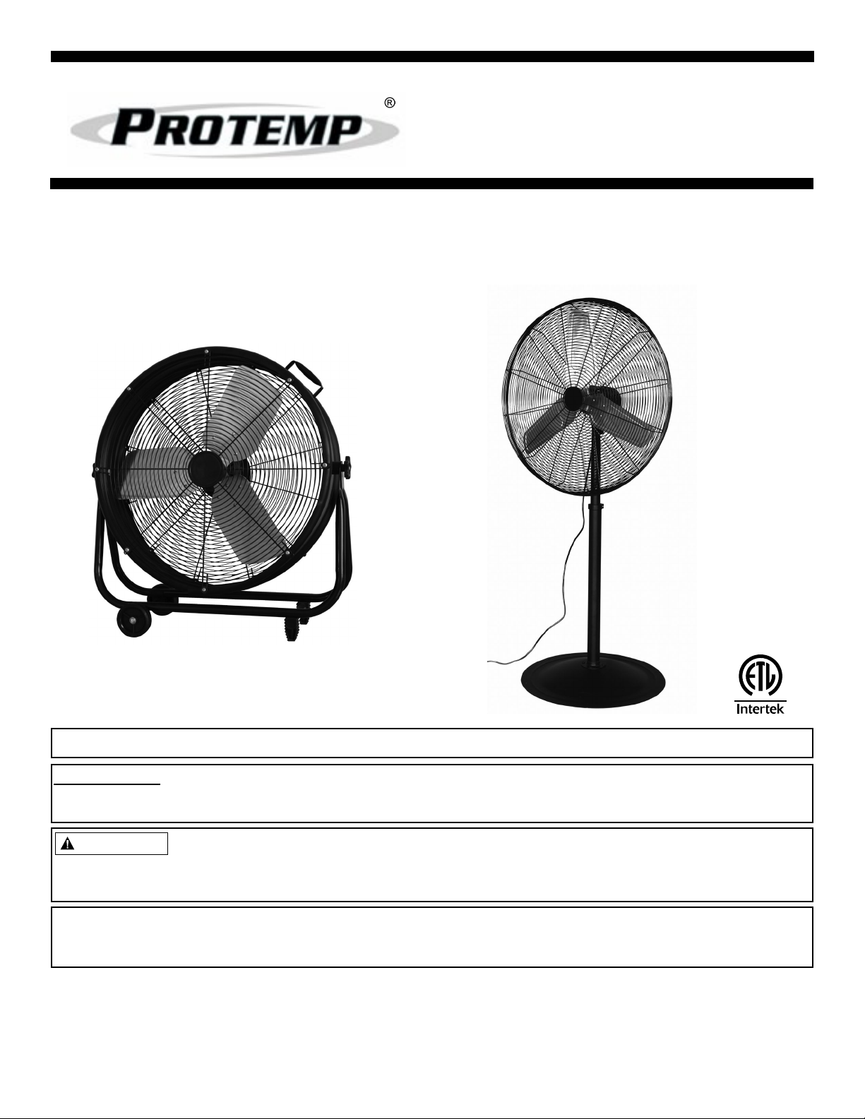
User’s Manual and
Operating Instructions
Model Numbers: PT-18W-DDF-A, PT-20F-DDF-A,
PT-20S-DDF, PT-24O-DDF, PT-24-DDF-L,
PT-30-DDF, PT-30P-DDF-L
&0
/
'
,
(
6
7
READ AND SAVE THESE INSTRUCTIONS
IMPORTANT: Read and understand all of the instructions in this manual before assembling,
starting, or servicing the fan. Improper use of this fan can cause serious injury. Keep this manual for
future reference.
CAUTION
For General Ventilating Use Only. Do Not Use To Exhaust Hazardous Or Explosive
Materials And Vapors. Never use the fan in spaces which contain products such as
gasoline, solvents, paint thinners, dust particles, volatile or airborne combustibles, or any unknown
chemicals.
This product meets and exceeds the requirements of OSHA 1910.212(a)(5), the standard which
regulates electric fan blade safety.
Please note the serial number of your fan, and write it on the back of this User’s Manual for future reference.
© 2014, Pinnacle Products International, Inc.
668 Stony Hill Road #302 Yardley, PA 19067 USA Toll Free: (800) 641-6996
Fax: (215) 891-8461 • Web: www.protemp.us • Email: info@pinnacleint.com
950451001-14
Page 2
User’s Manual and
Operating Instructions
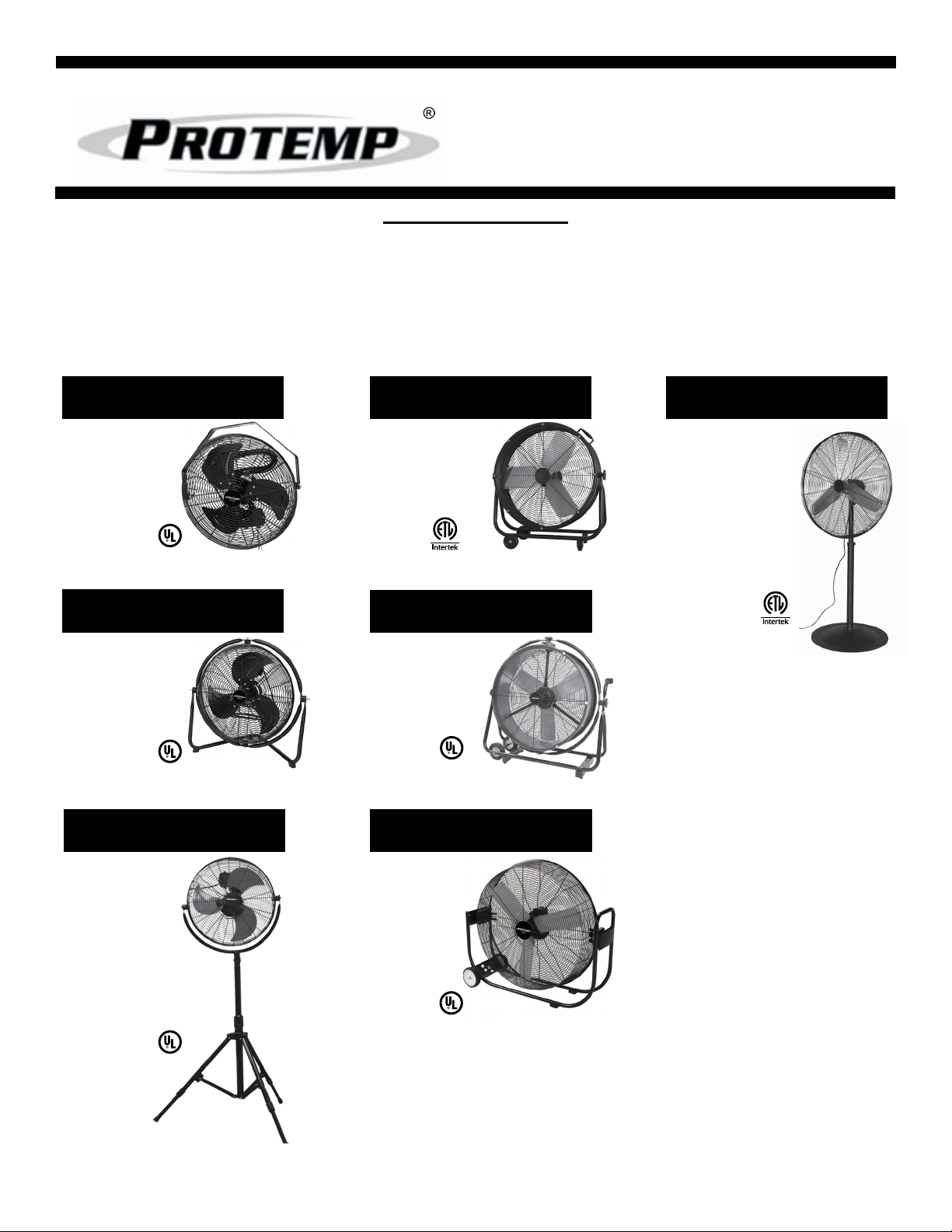
Table of Contents
Safety Information................................................................................................................................. 3
Notes Page............................................................................................................................................4
Troubleshooting Guide........................................................................................................................19
Warranty................................................................................................................................Back Cover
5
18” Wall Fan
PT-18W-DDF-A
6-7
20” Floor Fan
PT-20F-DDF-A
8-10
11
24” Barrel Fan
PT-24-DDF-L
&0
86
/
'
,
(
6
7
12-13
24” Omni Fan
PT-24O-DDF
14-16
17-18
30” Pedestal Fan
PT-30P-DDF-L
&0
86&
/
'
,
(
6
7
20” Shop Fan
PT-20S-DDF
30” Floor Fan
PT-30-DDF
© 2014, Pinnacle Products International, Inc. 2 HVF Air Circulator User’s Manual
Page 3
NEVER LEAVE A FAN
WARNING
WARNING
WARNING
WARNING
WARNING
WARNING
WARNING
WARNING
WARNING
WARNING
UNATTENDED WHILE
OPERATING OR WHILE
CONNECTED TO A POWER
SOURCE
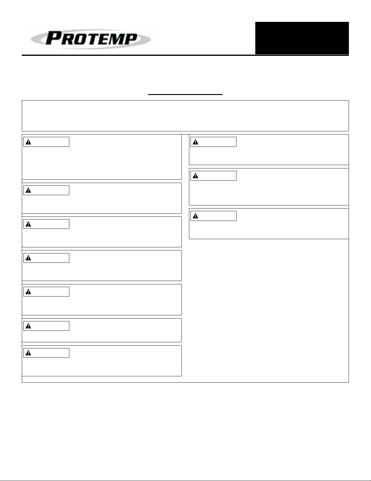
Safety Information
IMPORTANT: READ ALL INSTRUCTIONS CAREFULLY BEFORE ASSEMBLY, SERVICE OR
USE OF THIS FAN. FAILURE TO COMPLY WITH THESE INSTRUCTIONS COULD RESULT IN
SERIOUS PERSONAL INJURY AND / OR PROPERTY DAMAGE.
THIS IS A FAN - NOT A TOY!
TO REDUCE THE RISK OF
PERSONAL INJURY AND ELECTRIC SHOCK,
FANS SHOULD NOT BE PLAYED WITH OR
PLACED WHERE SMALL CHILDREN CAN
REACH IT.
To guard against electric shock
while operating, do not allow fan
to come in contact with other grounded objects
such as pipes, radiators, etc.
Risk of fire, electric shock, or
personal injury when performing
service or maintenance. Unplug or disconnect
the fan from the power supply before servicing.
CAUTION Automatically
Operated Device - To Reduce
The Risk Of Injury Disconnect From Power
Source Before Servicing
To Reduce The Risk Of Fire
Or Electric Shock, Do Not Use
This Fan With Any Solid- State Speed Control
Device.
To Reduce The Risk Of Electric
Shock And Injury To Persons, Do
Not Use In a Window.
To Reduce The Risk Of Electric
Shock, Do Not Expose To Water
Or Rain. This unit is designed for indoor use
only.
Installation work and electrical
wiring must be done by
qualified person (s) in accordance with all
applicable codes and regulations.
When servicing or replacing a
component requires the removal
or disconnection of a safety device, the safety
device is to be reinstalled or remounted as
previously installed before operating this fan.
Use this fan only in the manner
intended by the manufacturer.
If you have any questions, contact Customer
Service at 800-641-6996.
- Before operating always check fan for loose
or damaged parts. Inspect power cord for any
damage. Never use fan if any parts are
damaged or missing. Never use fan without
safety guards attached.
- Operate only on 120 volt 60 Hz (cycle) current
with a minimum of a 15 amp circuit.
- When used with an extension cord, use only
cord of proper size (Amp rating), UL listed, and
with receptacle to accept three prong grounded
plug furnished on the fan’s power cord. Always
keep power cord and extension cords away
from heat, oil, and sharp edges. Inspect cords
periodically and replace if damaged.
© 2014, Pinnacle Products International, Inc. 3 HVF Air Circulator User’s Manual
Page 4

NEVER LEAVE A FAN
UNATTENDED WHILE
OPERATING OR WHILE
CONNECTED TO A POWER
SOURCE
NOTES
__________________________________________________________________________________________
__________________________________________________________________________________________
__________________________________________________________________________________________
__________________________________________________________________________________________
__________________________________________________________________________________________
__________________________________________________________________________________________
__________________________________________________________________________________________
__________________________________________________________________________________________
__________________________________________________________________________________________
__________________________________________________________________________________________
__________________________________________________________________________________________
__________________________________________________________________________________________
__________________________________________________________________________________________
__________________________________________________________________________________________
__________________________________________________________________________________________
__________________________________________________________________________________________
__________________________________________________________________________________________
__________________________________________________________________________________________
__________________________________________________________________________________________
__________________________________________________________________________________________
__________________________________________________________________________________________
__________________________________________________________________________________________
__________________________________________________________________________________________
__________________________________________________________________________________________
__________________________________________________________________________________________
__________________________________________________________________________________________
__________________________________________________________________________________________
__________________________________________________________________________________________
__________________________________________________________________________________________
__________________________________________________________________________________________
__________________________________________________________________________________________
__________________________________________________________________________________________
__________________________________________________________________________________________
__________________________________________________________________________________________
__________________________________________________________________________________________
__________________________________________________________________________________________
__________________________________________________________________________________________
__________________________________________________________________________________________
__________________________________________________________________________________________
__________________________________________________________________________________________
__________________________________________________________________________________________
__________________________________________________________________________________________
© 2014, Pinnacle Products International, Inc. 4 HVF Air Circulator User’s Manual
Page 5
Wall Mount Installation
WARNING
NEVER LEAVE A FAN
UNATTENDED WHILE
OPERATING OR WHILE
CONNECTED TO A POWER
SOURCE
18” WALL FAN: PT-18W-DDF-A
1. Attach fan to wall or ceiling using Upper Bracket
(Item #6).
2. Be sure Upper Bracket (Item #6) is attached to a
suitable beam when hanging.
Tools Needed:
- 10mm Adjustable Wrench.
Exploded View
1
2
3
4
5
6 7
The installer MUST be
certain that the support bracket is
mounted to a minimum of a 2x4” stud, and that it
is able to support 50 pounds continuously.
9
8
10 11
12
17
15
14
18
16
Figure 1: Exploded View of PT-18W-DDF-A
Replacement Parts
Item # Description Part Number
1 Logo Plate 95-043-0370
2 Front Guard 95-032-0150
3
Fan Blade Assembly 95-003-06064
5
6 Upper Bracket 95-061-0100
7 Rear Guard 95-032-0250
8 Motor 95-030-0515
9 Switch Holder 95-031-0300
© 2014, Pinnacle Products International, Inc. 5 HVF Air Circulator User’s Manual
Item # Description Part Number
10 Switch Gasket 95-031-0340
11 Switch (Chain) 95-031-0110
12 Switch Cover 95-031-0500
13 Cord Bushing 95-026-0160
14 Pivot Washer 95-024-0300
15 Swivel Spacer 95-050-0185
16 Pivot Screw 95-024-0310
17 Capacitor 95-004-0215
18 Power Cord 95-026-0230
13
Page 6
20” FLOOR FAN: PT-20F-DDF-A
WARNING
Installation and Assembly
NEVER LEAVE A FAN
UNATTENDED WHILE
OPERATING OR WHILE
CONNECTED TO A POWER
SOURCE
1. Remove 1 screw from each Frame Support L and R
(Items #7* and #19*).
2. Slide Frame Support L and Frame Support R into
Support Frame (Item #21*) and line up holes for screw.
3. Re-attach screw to Frame Support L and Frame
Support R.
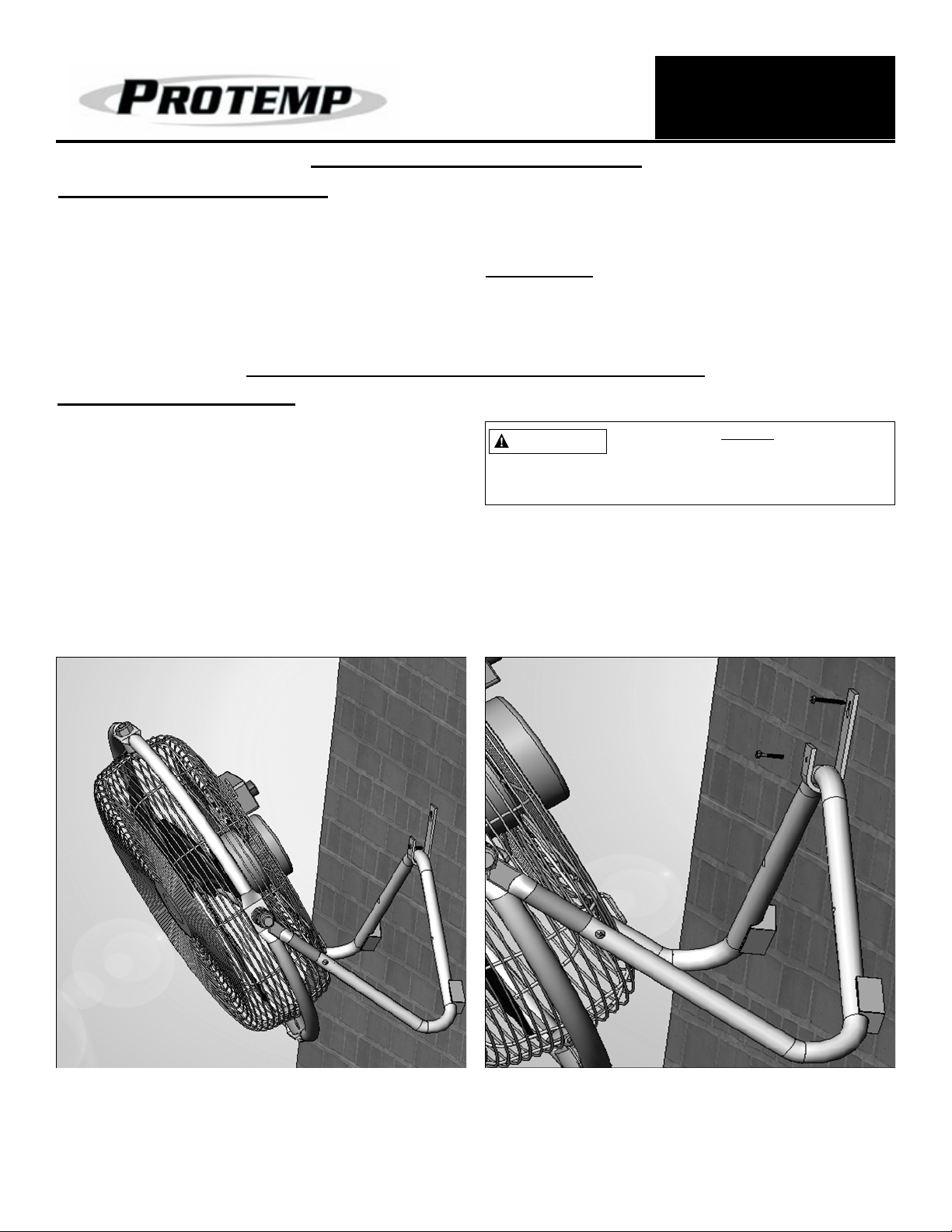
20” FLOOR FAN - OPTIONAL WALL MOUNT
Wall Mount Installation
1. Attach wall mount to stud (Item #24*)
2. Attach Lower Support Frame (Item #21*) to the Wall
Mount (Item #24*) by replacing rear part of Lower
Support Frame into hook of Wall Mount and resting
front and rear feet of fan (Items #17* and #18*) onto
the wall.
* On Page 7
4. Place the fan on level ground in a safe, desired position
then connect to an approved power source.
Tools Needed:
- Phillips head screwdriver.
-10 mm adjustable wrench.
The installer MUST be
certain that the support bracket is
mounted to a minimum of a 2x4”
stud, and that it is able to support 50 pounds
continuously.
NOTE: Fan must be mounted to wall so that both feet
are positioned against the wall surface. Mounting
this fan to a bare stud without both fan feet positioned against a flat surface will result in damage
to the fan.
Figure 2: Wall Mount Installation
Figure 3: Wall Mount Installation - Close Up
© 2014, Pinnacle Products International, Inc. 6 HVF Air Circulator User’s Manual
Page 7

Exploded View
NEVER LEAVE A FAN
UNATTENDED WHILE
OPERATING OR WHILE
CONNECTED TO A POWER
SOURCE
20” FLOOR FAN CONTINUED
1
Figure 4: Exploded View of PT-20F-DDF-A
2
3
4
6
5
7
21
20
8
9
10
11
12
13
14
15
16
23
22
24
19
18
17
Replacement Parts
Item # Description Part Number
1 Logo Plate 95-043-0405
2 Front Guard 95-032-0160
3
Fan Blade Assembly 95-003-06164
5
6 Frame Washer 95-024-0250
7 Frame-Support L 95-024-0265
8 Main Circle Tube 95-024-0280
9 Top Washer 95-024-0290
10 Rear Guard 95-032-0260
11 Motor 95-030-0525
12 Switch Holder 95-031-0310
© 2014, Pinnacle Products International, Inc. 7 HVF Air Circulator User’s Manual
Item # Description Part Number
13 Switch 95-031-0120
14 Switch Cover 95-031-0510
15 Cord Bushing 95-026-0165
16 Control Knob 95-027-0110
17 Front Foot 95-023-0220
18 Rear Foot 95-023-0230
19 Frame-Support R 95-024-0275
20 Swivel Spacer 95-050-0180
21 Lower Support Frame 95-024-0245
22 Power Cord 95-026-0240
23 Capacitor 95-004-0225
24 Wall Mount Kit 95-078-0100
Page 8

Installation and Assembly
WARNING
WARNING
NEVER LEAVE A FAN
UNATTENDED WHILE
OPERATING OR WHILE
CONNECTED TO A POWER
SOURCE
20” SHOP FAN: PT-20S-DDF
1. Remove Knob Screw (Item #15*) and Wing Nut (Item
#14*) from top of Post.
2. Slide Connector Bracket (Item #4*) onto top of post.
3. Line up holes on the Post and Connector Bracket
(Item #4*).
4. Re-insert the Knob Screw (Item #15) through the Post
and Connector Bracket (Item #14*) and tighten firmly
with the Wing Nut (Item #14*).
Tripod Operation Instructions
TRIPOD LEG OPERATION
1. Fold legs out and slide support bracket to center of leg.
2. To adjust leg height; rotate locking ring clockwise to
loosen.
NOTE: Keep a firm grip on the tripod while leg is
unlocked! The leg will collapse into itself unless
held tightly.
NOTE: Be certain to make all three legs the same
height. Setting legs to different heights will make
the fan unbalanced and COULD FALL OVER.
3. Slide leg extension to desired height.
4. Rotate locking ring counter-clockwise and tighten firmly.
Be sure the leg is secure before moving to next leg.
5. Repeat steps 2-4 for remaining legs.
5. Place the fan on level ground in a safe, desired position
then connect to an approved power source.
6. Set desired tripod stand height following “Tripod
Operation Instructions” below.
* On Page 10
TRIPOD CENTER POST OPERATION
1. To change the post height; rotate locking ring
counter-clockwise to unlock post.
NOTE: Be certain to keep a firm grip on post while
unlocked! The fan will slide down to its lowest
point if it is not held and slowly moved to desired
position.
2. Raise or lower post to desired position.
3. Rotate locking ring clockwise to lock post and tighten
firmly.
DO NOT MOVE OR ADJUST
FAN WHILE IN OPERATION.
THIS CAN CAUSE DAMAGE TO FAN AND
INJURY TO THE OPERATOR.
OPTIONAL CEILING MOUNT
Installation and Assembly
1. Attach Ceiling Mounting Kit (Item #16*) to 2x4” stud
that is able to support 50 lbs continuously using
M6x40mm screw. (See Figure 5**)
The installer MUST be
certain that the support bracket is
mounted to a minimum of a 2x4”
stud, and that it is able to support 50 pounds
continuously.
3. Be Certain that the Safety Pin lines up with the groove
on the Connector Bracket (Item #4). (See Figure 6**)
© 2014, Pinnacle Products International, Inc. 8 HVF Air Circulator User’s Manual
2. Slide Connector Bracket (Item #4*) onto Ceiling
Mounting Post. (See Figure 7**)
4. Rotate the entire fan so the safety pin locks into place
and the holes on the Mounting Post line up with the
holes on the Connector Bracket (Item #4*). (See Figure
8**)
5. Insert the Knob Screw (Item #15*) through the
Mounting Post and Connector Bracket (Item #4*) and
tighten firmly with the Wing Nut (Item #14*).
(See Figure 8**)
* On Page 10
** On Page 9
Page 9

NEVER LEAVE A FAN
UNATTENDED WHILE
OPERATING OR WHILE
CONNECTED TO A POWER
SOURCE
20” SHOP FAN CONTINUED - OPTIONAL CEILING MOUNT
Figure 5:
Optional Ceiling Mount
Figure 6:
Optional Ceiling Mount
Figure 7:
Optional Ceiling Mount
Figure 8:
Optional Ceiling Mount
© 2014, Pinnacle Products International, Inc. 9 HVF Air Circulator User’s Manual
Page 10

Exploded View
NEVER LEAVE A FAN
UNATTENDED WHILE
OPERATING OR WHILE
CONNECTED TO A POWER
SOURCE
20” SHOP FAN CONTINUED
123
4
567 8 91011
13
121514
16
Figure 9: Exploded View of PT-20S-DDF
Replacement Parts
Item # Description Part Number
1 Logo Plate 95-043-0420
2 Front Guard 95-032-0185
3 Fan Blade Assembly 95-003-0616
4 Frame 95-001-0500
5 Rear Guard 95-032-0285
6 Motor 95-030-0525
7 Switch Holder 95-031-0335
8 Power Cord 95-026-0270
© 2014, Pinnacle Products International, Inc. 10 HVF Air Circulator User’s Manual
Item # Description Part Number
9 Power Switch 95-025-0600
10 Capacitor 95-004-0250
11 Bushing 95-026-0180
12 Switch Cover 95-031-0540
13 Tripod 95-040-0100
14 Wing Nut 95-075-0400
15 Base Knob 95-015-0220
16 Ceiling Mount Kit 95-078-0300
Page 11

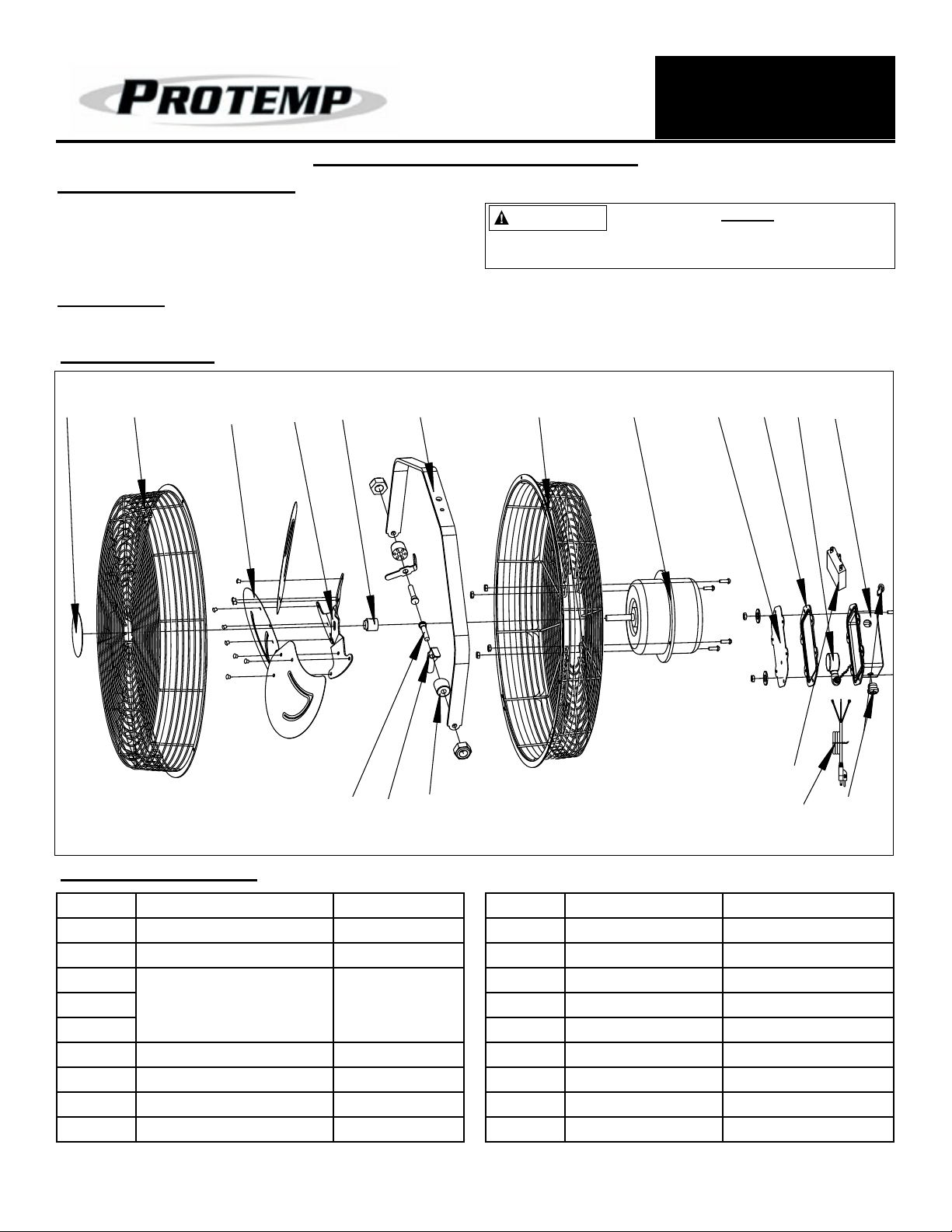
24” BARREL FAN: PT-24-DDF-L
Installation and Assembly
1. Place the fan on level ground in a safe, desired
position then connect to an approved power source.
Exploded View
NEVER LEAVE A FAN
UNATTENDED WHILE
OPERATING OR WHILE
CONNECTED TO A POWER
SOURCE
NOTE: This model CAN NOT be wall mounted.
16
Figure 10: Exploded View of
PT-24-DDF-L
101112131415
17
9
18
8
19
20 21 22
34567
2
1
Replacement Parts
Item # Description Part Number
1 Power Cord 95-026-1000
2 Control Knob 95-027-1000
3 Motor Cover 95-035-1000
4 Power Switch 95-031-1100
5 Rear Guard 95-032-1000
6 Switch Cover 95-031-1000
7 Motor 95-030-1000
8 Handle 95-006-1000
9 Barrel 95-001-1000
10 Axle Cap 95-008-1000
11 Wheel 95-008-1001
© 2014, Pinnacle Products International, Inc. 11 HVF Air Circulator User’s Manual
Item # Description Part Number
12 Wheel Axle 95-008-1002
13 Axle Sleeve 95-008-1003
14 Wheel Carrier 95-008-1004
15 Front Guard 95-032-1001
16 Fan Frame 95-009-1000
17 Fan Blade Assembly 95-003-1000
18 Foot 95-023-1000
19 Frame Braket 95-009-1001
20 Adjustment Bolt 95-015-1000
21 Adjustment Boly Bushing 95-015-1001
22 Adjustment Knob 95-015-1002
Page 12

24’’ OMNI DIRECTIONAL FAN: PT-24O-DDF
Installation and Assembly
1. Place the fan on level ground in a safe, desired position
then connect to an approved power source.
Exploded View
3
1
2
4
5
10
8
6
7
9
11
12
13
NEVER LEAVE A FAN
UNATTENDED WHILE
OPERATING OR WHILE
CONNECTED TO A POWER
SOURCE
16
15
17
14
19
18
30
31
Figure 11: Exploded View of: PT-24O-DDF
Replacement Parts
Item # Description Part Number
1 Front Guard 95-032-0170
2 Fan Barrel 95-001-0400
3 Power Knob 95-027-0130
4 Power Knob Holder 95-031-0325
5 Capacitor 95-004-0235
6 Power Cord 95-026-0255
7 Motor 95-030-0535
8 Motor Mount Assembly 95-030-0555
9 Motor Cooling Fan 95-030-0556
10 Fan Blade Assembly 95-003-0621
11 Rear Guard 95-032-0275
12 Front Leg 95-009-0600
13 Horizontal Adj. Knob 95-015-0150
14 Spacer 95-050-0200
15 Outer Ring Frame 95-024-0320
20
29
28
27
26
25
22
23
24
Item # Description Part Number
16 Vertical Adj. Knob 95-015-0150
17 Wall Mount 95-078-0200
18 Handle Pad 95-007-0100
19 Spacer 95-050-0200
20 Handle Arm 95-006-0300
21 Rear Leg 95-009-0610
22 Large Base Cap 95-024-0410
23 Large Base 95-024-0400
24 Foot Pad 95-023-0240
25 Wall Bracket - L 95-077-0100
26 Wall Bracket - R 95-077-0110
27 Small Base 95-024-0500
28 Small Base Cap 95-024-0510
29 Wheel 95-004-0155
30 Lower Mount 95-024-0325
31 Logo Plate 95-043-0331
21
© 2014, Pinnacle Products International, Inc. 12 HVF Air Circulator User’s Manual
Page 13

CONNECTED TO A POWER
WARNING
24” OMNI FAN - OPTIONAL WALL MOUNT
NEVER LEAVE A FAN
UNATTENDED WHILE
OPERATING OR WHILE
SOURCE
Wall Mount Installation
1. Attach Wall Mount (Item #17*) to wood stud as shown
below.
2. Slide Wall Bracket L (Item #25*) and Wall Bracket
R (Item #26*) on Large Base (Item #23*) onto Wall
Mount.
* On Page 12
Wall Mount (Item #17*)
The installer MUST be
certain that the support bracket is
mounted to a minimum of a 2x4” stud, and that it
is able to support 105 pounds continuously.
Tools Needed
-Flat head Screw Driver.
2”x4”
STUD
Figure 12: Wall Mount installation Close Up
Handle Arm (Item #20*)
Wall
Large Base
(Item #23*)
Wall Mount
(Item #17*)
Figure 13: Wall Mount installation
© 2014, Pinnacle Products International, Inc. 13 HVF Air Circulator User’s Manual
Page 14

30” FLOOR FAN: PT-30-DDF
NEVER LEAVE A FAN
UNATTENDED WHILE
OPERATING OR WHILE
CONNECTED TO A POWER
SOURCE
Installation and Assembly
1. Place the fan on level ground in a safe, desired position
then connect to an approved power source.
Exploded View
1
2
4
7
8
9
6
5
NOTE: This fan uses a folding wheel design. For quick
assembly, simply swing the wheels out and snap to
lock in place.
10
25
15
16
19
17
22
11
18
21
20
23
24
3
25
12
Figure 14: Exploded View of PT-30-DDF
Replacement Parts
Item# Description Part Number
1 Front Guard 95-032-0140
2 Front Swivel Bracket 95-050-0100
3 Fan Blade Assy 95-003-0501
4 Motor 95-030-0500
5 Frame Foot 95-023-0200
6 Cart Frame 95-009-0400
7 Swivel Cover 95-050-0106
8 Frame Swivel Bracket 95-050-0111
9 Frame Upper Swivel Latch 95-050-0120
10 Swivel Latch Pin 95-050-0131
11 Frame Cap 95-011-0300
12 Wheel 95-008-0165
13
14
Item# Description Part Number
13 Wheel Axle 95-008-0260
14 Wheel Frame 95-008-0500
15 Upper Swivel Housing 95-050-0141
16 Frame Lower Swivel Latch 95-050-0150
17 Latch Spring 95-060-0155
18 Lower Swivel Housing 95-050-0161
19 Rear Guard 95-032-0240
20 Rear Swivel Bracket 95-050-0170
21 Capacitor 95-004-0200
22 Power Switch 95-025-0500
23 Rear Motor Cover 95-048-0100
24 Power Cord 95-026-0150
25 Guard Screw 95-033-0225
© 2014, Pinnacle Products International, Inc. 14 HVF Air Circulator User’s Manual
Page 15

NEVER LEAVE A FAN
WARNING
UNATTENDED WHILE
OPERATING OR WHILE
CONNECTED TO A POWER
30” FLOOR FAN - OPTIONAL CEILING MOUNT
SOURCE
Ceiling Mount Installation
MOUNTING BRACKET INSTALLATION:
1. Remove Wheel Frame (Item #15)
2. Attach Cart Frame to Ceiling beam using U-bolts
(Item #5).
3. Assemble and attach Ceiling Mount Assembly as
shown in Figure 15 below.
Tools Needed
- Phillips and flat head screw driver.
- 10 mm adjustable wrench.
Ceiling Kit Exploded View
3
5
2
4
1
The installer MUST be
certain that the support bracket is
mounted to a minimum of a 2x4” stud, and that it
is able to support 105 pounds continuously.
This 30” Floor Fan (PT-30-DDF) is approved for use with
California’s BAR-97 Emissions Inspection System and meets
all BAR-97(EIS) required specications and standards
6
7
8
9
Figure 15: Exploded View of PT-30-DDF (ceiling mount kit)
Ceiling Kit Replacement Parts
Item# Description Part Number
1 Safety Cable Assy 95-060-0100
2 Nut for Ceiling Swivel Pin 95-060-0180
3 Nut 95-060-0125
4 Upper Ceiling Bracket 95-060-0110
5 U-Bolt 95-060-0120
Item# Description Part Number
6 Top Washer 95-060-0120
7 Lower Ceiling Bracket 95-060-0160
8 Tapping Screw 5-15mm 95-060-0195
9 Ceiling Swivel Pin 95-060-0170
© 2014, Pinnacle Products International, Inc. 15 HVF Air Circulator User’s Manual
Page 16

30” FLOOR FAN - OPTIONAL CEILING MOUNT CONTINUED
WARNING
Ceiling Mount Installation
SAFETY CABLE INSTALLATION:
1. After the fan is securely mounted, feed the safety cable
between one of the swivel brackets as shown in Figure
15.
2. Pull safety cable through and secure cable with safety
cable U-bolt as shown in Figure 17.
3. Take other end of cable and wrap around beam
4. Secure cable loop as shown in step 2. Be sure there
is approximately 2 inches of slack in the safety cable
once both ends are secured.
5. Repeat on other side of fan so there are two safety
cables.
NEVER LEAVE A FAN
UNATTENDED WHILE
OPERATING OR WHILE
CONNECTED TO A POWER
SOURCE
Tools Needed
- Phillips and flat head screw driver.
- 10 mm adjustable wrench
The installer MUST be
certain that the support bracket is
mounted to a minimum of a 2x4” stud, and that it
is able to support 105 pounds continuously.
Figure 16: Safety Cable Installation
Figure 17: Safety Cable Installation - Close Up
© 2014, Pinnacle Products International, Inc. 16 HVF Air Circulator User’s Manual
Page 17

30” PEDESTAL FAN: PT-30P-DDF-L
NEVER LEAVE A FAN
UNATTENDED WHILE
OPERATING OR WHILE
CONNECTED TO A POWER
SOURCE
Installation and Assembly
Tools Needed:
Pliers
Phillips head screwdriver
Flat head screwdriver
10mm / adjustable wrench
Parts Included In Box:
(1) Base
(1) Front Guard
(1) Rear Guard
(1) Motor Assembly
(1) Fan Blade Assembly
(1) Locking Collar
(1) Upper Support Pole
(1) Lower Support Pole
Motor Assembly
Pivot Bolt
Nut
Knob
Screw
Upper Support Pole
Figure 18: Attaching Motor to Motor Support Assembly
Rear Guard
1. Mount the lower support pole to the base
using four (4) 20 mm cap bolts. Secure tightly
with four (4) nuts.
2. Remove the screw at the top of the lower
support pole.
3. Slide upper support pole into lower support
pole.
4. Line up the hole in the locking collar with the
hole in the side of the lower support pole.
Secure locking collar to lower support pole
with screw removed in step 2.
5. Secure and tighten locking collar with
attached knob screw.
6. Mount motor assembly to upper support pole
using 25 mm pivot bolt and nut.
7. Attach knob screw to motor assembly
through lower hole and curved slot. Adjust
motor assembly angle as desired and tighten
knob screw to secure in place.
8. Slide rear guard onto motor studs and secure
with washers and nuts. Secure and tighten
firmly.
9. Loosen the set screw on the back of the fan
blade assembly and slide onto the motor
shaft.
10. Position set screw over the flat groove on the
motor shaft and tighten set screw. Be sure
the set screw is on the groove and front of
the fan blade assembly is flush with the front
of the shaft before tightening.
CAUTION
This will cause the fan blade to not spin properly
and can cause damage to your fan! Be sure that fan
shaft is flush with front of fan blade assembly.
Do NOT slide fan blade screw
beyond the groove on the shaft!
11. Attach the front guard using four (4) bolts and
Motor
nuts. line up holes on on front and rear guard
and tighten firmly.
NOTE: This model CAN NOT be wall mounted
Figure 19: Attaching Rear Guard to Motor
© 2014, Pinnacle Products International, Inc. 17 HVF Air Circulator User’s Manual
Page 18

30” PEDESTAL FAN
NEVER LEAVE A FAN
UNATTENDED WHILE
OPERATING OR WHILE
CONNECTED TO A POWER
SOURCE
Exploded View
11
10
89
7
6
5
4
3
2
1
1
Figure 20: Exploded View of
PT-30P-DDF-L
Replacement Parts
Item # Description Part Number
1 Base 95-024-1000
2 Lower Support Pole 95-017-1000
3 Locking Knob Screw 95-015-1003
4 Locking Collar 95-017-1001
5 Locking Collar Nut 95-017-1002
6 Upper Support Pole 95-017-1003
© 2014, Pinnacle Products International, Inc. 18 HVF Air Circulator User’s Manual
Item # Description Part Number
7 Motor 95-030-1100
8 Rear Guard 95-032-1100
9 Fan Blade Assembly 95-003-1100
10 Front Guard 95-032-1101
11 Logo Plate 95-043-1000
12 Hardware Kit 95-100-1000
Page 19

Troubleshooting Guide
Problem Possible Cause Corrective Action
NEVER LEAVE A FAN
UNATTENDED WHILE
OPERATING OR WHILE
CONNECTED TO A POWER
SOURCE
Fan does not operate
Reduced Air Flow
Humming sound but no
operation
Excess Noise (vibration,
squealing)
1. No power
2. Bad motor Replace motor
1. Obstruction
2. Bad switch or capacitor
1. Bad capacitor Replace capacitor
1. Fan is not on level ground Turn off fan, and move unit to smooth level surface.
2. Guard is not secure Check guard screws to be sure all are tight.
Inspect power cord for damage. Be sure unit is
plugged in and turned on.
Turn off and unplug fan. Remove guard and make sure
nothing is obstructing the fan blades.
Replace switch or capacitor (Note: To prolong life of
fan, operate fan first in 1(LOW) for 5-10 seconds before
switching to higher speed.
© 2014, Pinnacle Products International, Inc. 19 HVF Air Circulator User’s Manual
Page 20

1 YEAR LIMITED WARRANTY
PINNACLE PRODUCTS INTERNATIONAL, INC. WARRANTS THIS
PRODUCT TO THE ORIGINAL RETAIL PURCHASER ONLY, TO BE
FREE FROM DEFECTS IN MATERIAL AND WORKMANSHIP FOR
A PERIOD OF ONE (1) YEAR FROM THE DATE OF INITIAL PURCHASE. THIS PRODUCT MUST BE PROPERLY INSTALLED, MAINTAINED AND OPERATED IN ACCORDANCE WITH THE INSTRUCTIONS PROVIDED.
PINNACLE PRODUCTS INTERNATIONAL, INC. REQUIRES REA-
SONABLE PROOF OF YOUR DATE OF PURCHASE FROM AN
AUTHORIZED RETAILER OR DISTRIBUTOR. THEREFORE, YOU
SHOULD KEEP YOUR SALES SLIP, INVOICE, OR
CANCELLED CHECK FROM THE ORIGINAL PURCHASE. THIS
LIMITED WARRANTY SHALL BE LIMITED TO THE REPAIR OR
REPLACEMENT OF PARTS, WHICH PROVE DEFECTIVE UNDER
NORMAL USE AND SERVICE WITHIN THE
WARRANTY PERIOD, AND WHICH PINNACLE PRODUCTS
INTERNATIONAL, INC. SHALL DETERMINE AT ITS
REASONABLE DISCRETION.
THIS WARRANTY DOES NOT APPLY TO PRODUCTS
PURCHASED FOR RENTAL USE.
THIS LIMITED WARRANTY DOES NOT COVER REPLACEMENT OF
BELTS OR TIGHTENING OF BELTS, OR ANY
FAILURES OR OPERATING DIFFICULTIES DUE TO NORMAL
WEAR AND TEAR, ACCIDENT, ABUSE, MISUSE, ALTERATION,
MISAPPLICATION, IMPROPER INSTALLATION OR IMPROPER
MAINTENANCE AND SERVICE BY YOU OR ANY THIRD PARTY.
FAILURE TO PERFORM NORMAL AND ROUTINE MAINTENANCE
ON THE FAN, SHIPPING DAMAGE, DAMAGE RELATED TO
INSECTS, BIRDS, OR ANIMALS OF ANY KIND, AND DAMAGE DUE
TO WEATHER CONDITIONS ARE ALSO NOT COVERED. IN ADDITION, THE LIMITED WARRANTY DOES NOT COVER DAMAGE TO
THE FINISH, SUCH AS SCRATCHES, DENTS, DISCOLORATION,
RUST OR OTHER WEATHER DAMAGE, AFTER PURCHASE.
ALL TRANSPORTATION COSTS FOR THE RETURN OF THE DAMAGED PRODUCT OR PARTS WILL BE THE
RESPONSIBILITY OF THE PURCHASER. UPON RECEIPT OF DAMAGED ITEM, PINNACLE PRODUCTS INTERNATIONAL, INC. WILL
EXAMINE THE ITEM AND DETERMINE IF
DEFECTIVE.
NEVER LEAVE A FAN
UNATTENDED WHILE
OPERATING OR WHILE
CONNECTED TO A POWER
SOURCE
PINNACLE PRODUCTS INTERNATIONAL, INC. WILL REPAIR
OR REPLACE AND RETURN THE ITEM, FREIGHT PRE-PAID. IF
PINNACLE PRODUCTS INTERNATIONAL, INC. FINDS THE ITEM
TO BE IN NORMAL OPERATING CONDITION, OR NOT DEFECTIVE, THE ITEM WILL BE RETURNED FREIGHT
COLLECT.
THIS LIMITED WARRANTY IS IN LIEU OF ALL OTHER EXPRESS
WARRANTIES. PINNACLE PRODUCTS INTERNATIONAL, INC.
DISCLAIMS ALL WARRANTIES FOR PRODUCTS THAT ARE PURCHASED FROM SELLERS OTHER THAN AUTHORIZED RETAILERS OR DISTRIBUTORS.
AFTER THE PERIOD OF THE ONE (1) YEAR LIMITED
WARRANTY EXPIRES, PINNACLE PRODUCTS INTERNATIONAL,
INC. DISCLAIMS ANY AND ALL IMPLIED WARRANTIES,
INCLUDING WITHOUT LIMITATION THE IMPLIED WARRANTIES
OF MERCHANTABILITY AND FITNESS FOR A PARTICULAR
APPLICATION. FURTHER, PINNACLE PRODUCTS
INTERNATIONAL, INC. SHALL HAVE NO
LIABILITY WHATSOEVER TO PURCHASER OR ANY THIRD PARTY
FOR ANY SPECIAL, INDIRECT, PUNITIVE,
INCIDENTAL, OR CONSEQUENTIAL DAMAGES. PINNACLE
PRODUCTS INTERNATIONAL, INC. ASSUMES NO
RESPONSIBILITY FOR ANY DEFECTS CAUSED BY THIRD PARTIES. THIS LIMITED WARRANTY GIVES THE
PURCHASER SPECIFIC LEGAL RIGHTS; A PURCHASER MAY
HAVE OTHER RIGHTS DEPENDING UPON WHERE HE OR SHE
LIVES. SOME STATES DO NOT ALLOW THE EXCLUSION OR LIMITATION OF SPECIAL, INCIDENTAL OR
CONSEQUENTIAL DAMAGES, OR LIMITATIONS ON HOW LONG
A WARRANTY LASTS, SO THE ABOVE EXCLUSION AND LIMITATIONS MAY NOT APPLY TO YOU.
PINNACLE PRODUCTS INTERNATIONAL, INC. DOES NOT
AUTHORIZE ANY PERSON OR COMPANY TO ASSUME FOR
IT ANY OTHER OBLIGATION OR LIABILITY IN CONNECTION
WITH THE SALE, INSTALLATION, USE, REMOVAL, RETURN,
OR REPLACEMENT OF ITS EQUIPMENT, AND NO SUCH REPRESENTATIONS ARE BINDING ON PINNACLE PRODUCTS
INTERNATIONAL, INC.
Register Online at: www.protemp.us/Product_Registration.php
ALWAYS BE SURE TO SPECIFY MODEL NUMBER AND SERIAL NUMBER WHEN MAKING ANY CLAIM
WITH PINNACLE PRODUCTS INTERNATIONAL, INC. FOR YOUR CONVENIENCE USE THE SPACE
PROVIDED BELOW TO LIST THIS INFORMATION:
Model #: ____________________ Serial #: ______________________
Date of Purchase: _________________
© Pinnacle Products International, Inc.
668 Stony Hill Road #302 Yardley, PA 19067 USA Toll Free: (800) 641-6996
Fax: (215) 891-8461 • Web: www.protemp.us • Email: info@pinnacleint.com
 Loading...