

Protekdevices CX12LC, CX12 Datasheet
05017
CX12
thru
. . . engineered solutions for the transient environment™
APPLICATIONS
✔ High Speed Video Camera
✔ Coaxial Ethernet
✔ High Speed Data Lines
IEC COMPATIBILITY (EN61000-4)
✔ 61000-4-5 (Surge): 24A, 8/20µs - Level 2(Line-Gnd) & Level 3(Line-Line)
FEATURES
✔ Meets IEC 1000-4-5 Industry Requirements
✔ BNC Connection
✔ Low Capacitance
✔ Completely Enclosed Aluminum Housing
✔ Low Clamping Voltage
✔ Nanosecond Response Time
✔ Long Life and Maintenance Free
✔ Finger Safe Connectors
MECHANICAL CHARACTERISTICS
✔ Metal Package
✔ Weight 161 Grams (Approximate)
✔ Device Marking: Part Number, Logo
DESCRIPTION
The CX12 series is a two stage, hybrid surge protector designed to protect interfacing equipment from
induced lightning or switching transients. The multistage technique has proven to be the most cost
effective and reliable method for protecting sensitive electronic equipment. Employing state-of-the-art
avalanche junction diode technology, these devices provide superior performance for video, Ethernet,
Token Ring or other LAN interface systems. They are in-line modules with easy interconnecting terminals. A
completely enclosed aluminum housing provides EMC shielding to meet industry standard requirements.
The enclosure has two female BNC type connections for easy installation. The case is ground for those
installations that require external ground connections.
CX12LC
COAXIAL PROTECTOR
Surgebuster
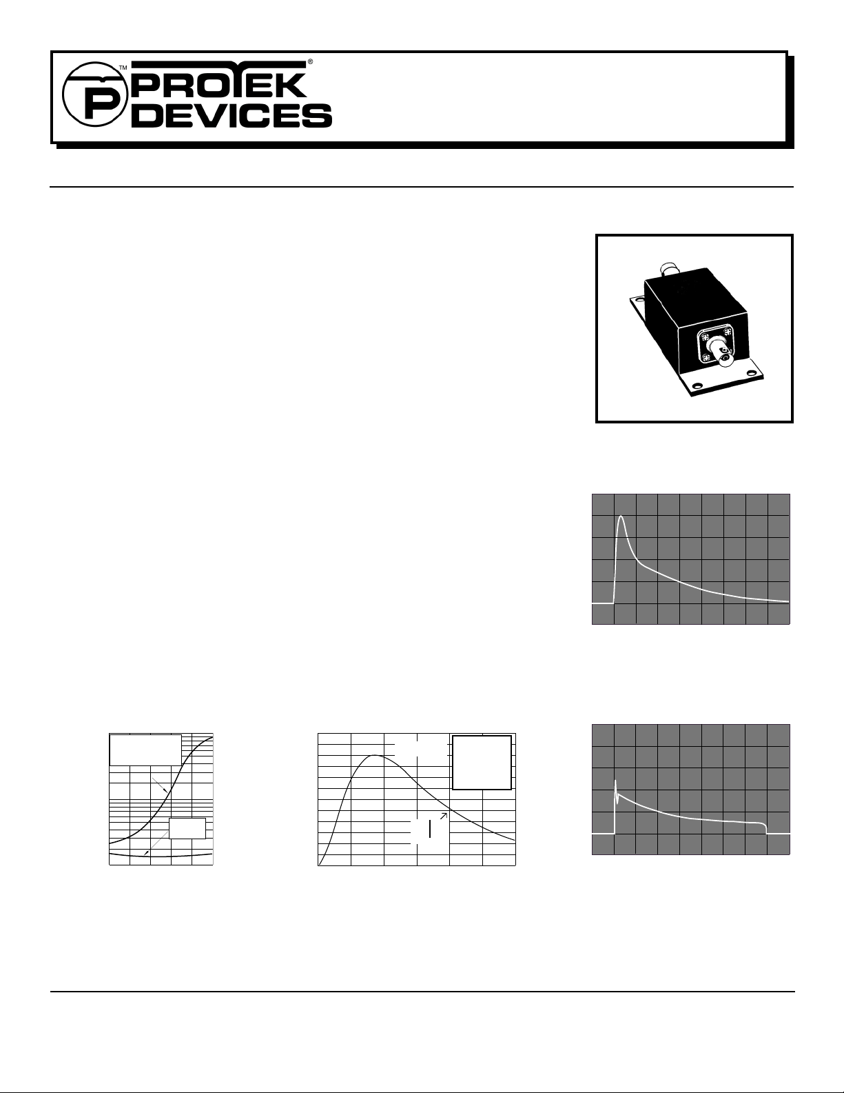
CX12 PACKAGE
TRANSIENT VOLTAGE THREAT
2K
1K
Current - Amperes
0
0 20 40 60 80 100 120 140 160
FIGURE 1
CONDITION
Time µs
®
LINEAR VS NON-LINEAR CAPACITANCE
FIGURE 3
1000
Industry Standard
Low Capacitance
Solid State Protector
100
ProTek’s
CX12LC
C - TVS Capacitance - pF
10
0 1 2 3 4 5
V
- Circuit Operating - Volts
(OP)
Figure 3 shows a comparison of capacitance between a
industrial standard device (Top Line) and the ProTek Device
CX12LC (Bottom Line). Due to the drastic change in the
capacitance of the product (Top Line), signal distortion,
loss of data or even access into the computer may be a
problem.
05017.R2 7/02
FIGURE 4
PULSE WAVE FORM
120
PP
100
80
60
40
20
- Peak Pulse Current - % of I
PP
I
0
0 5 10 15 20 25 3 0
t
f
Peak Value I
-t
e
td = t
PP
IPP/2
Test
Waveform
Parameters
tf = 8µs
td = 20µs
t - Time - µs
1
CX 12LC CLAMPING VOLTAGE
FIGURE 2
30
20
10
Current - Amperes
0
0 20 40 60 80 100 120 140 160
Time µs
Figure 1 and 2 are photographs of digitized waveforms
showing a typical transient voltage and the clamping
action of the CX12LC module. The device was subjected to a 2000A, 8/20µs impulse waveform in accordance with ANSI C62.36. The CX12 has an operating
frequency range up to 10MHz and the CX12LC up to
100MHz.
www.protekdevices.com
DEVICE CHARACTERISTICS
CX12
and
CX12LC
MAXIMUM RATINGS @ 25°C
Peak Operating Line Voltage (V OP )
Operating Line Current (I O )
Maximum Transient Voltage
Maximum Transient Current
Maximum Leakage Current
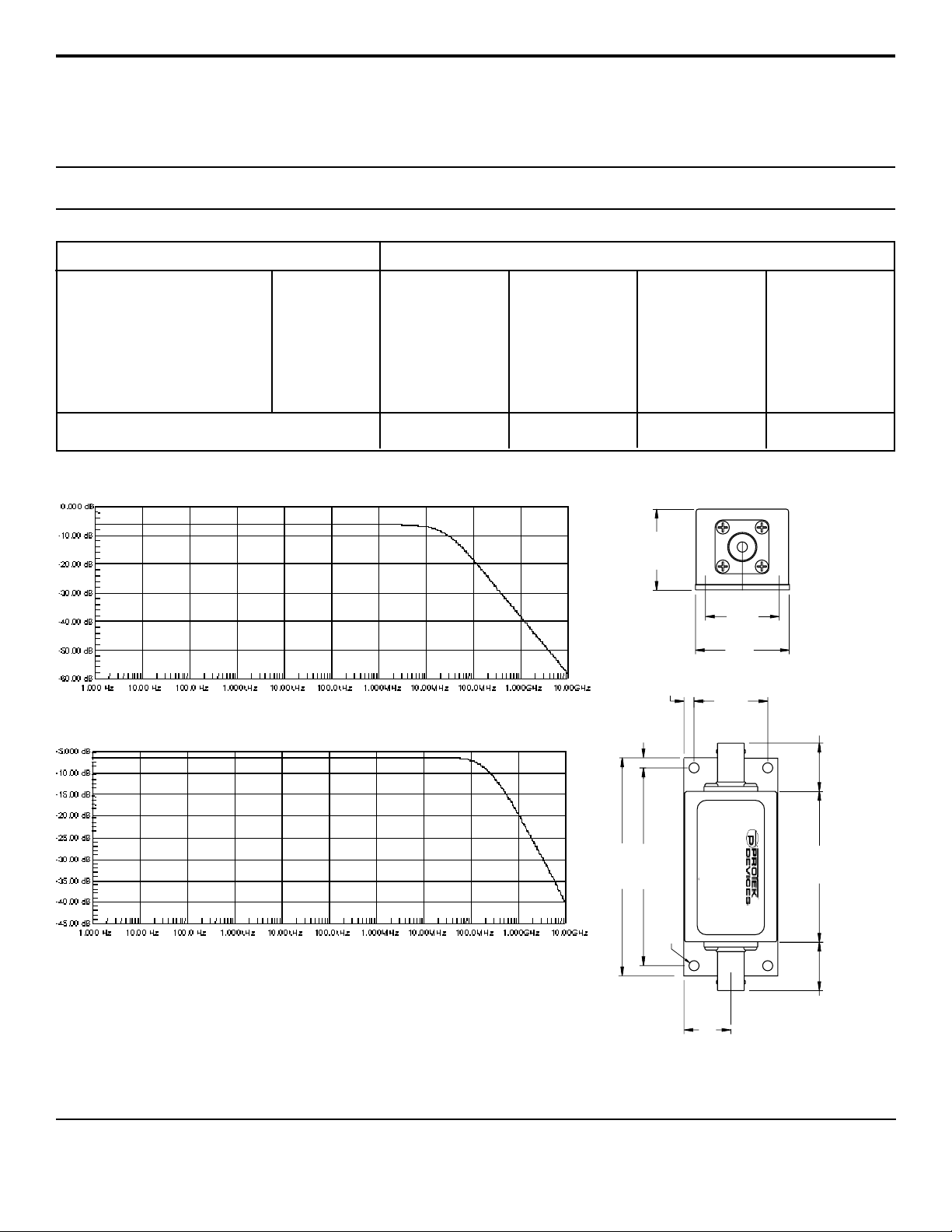
CX12 Frequency Responce -3 dB
CX12LC Frequency Responce -3 dB
Operating & Storage Temperature
Response Time
±12 V
200mA
20kV
3000A (8/20µs)
5µA
@ 30MHz
@ 200MHz
-40° to +85°C
< 10 ns
* Other Voltages Available Consult Factory
Frequency Responce CX12
Frequency Responce CX12LC
ELECTRICAL CHARACTERISTICS @ 25°C
MAXIMUM
PROTEK
PA RT
NUMBER
CX12
CX12LC
CLAMPING
VOLTAGE
*
Line-Ground
500A @ 8/20 ms
V
C
VOLTS
24
28
1.21”
(30.73 mm)
0.15”
(3.81mm)
RESISTANCE
MAXIMUM
LINE
THRUPUT
R
OHMS
3
10
(27.54 mm)
1.10”
(27.94 mm)
1.40”
(35.56 mm)
1.10”
TYPICAL
CAPACITANCE
@ 0 V, 1 MHz
C
pF
200
25
0.72”
(18.29 mm)
INSTALLATION
The CX12 series is designed with a female BNC type connector on both ends for
easy installation. Disconnect the video or data line from the sensitive equipment.
Insert the CX12 in the line near the AC power outlet of the equipment to be
protected. Install a cable in between the CX12 and the equipment to be protected. Attach a ground wire between the case of the CX12 and the equipment AC
power ground, or to the coax shield as required.
0.150” DIA. (3.81 mm) Mounting Holes
(74.93 mm)
(82.55 mm)
2.95”
3.25”
LINE
CAUTION:
CAUTION: Mounting plate must be
be connected to earth ground
connected to earth ground
CX 12 - COAXIAL
LINE PROTECTOR
LINE PROTECTOR
CX12 COAXIAL
Mounting plate must
EQUIPMENT
0.70”(17.78 mm)
www.protekdevices.com205017.R2 7/02
2.25”
(57.15 mm)
0.72”
(18.29 mm)
 Loading...