

05021
704-15K36
&
. . . engineered solutions for the transient environment™
704-15K36T
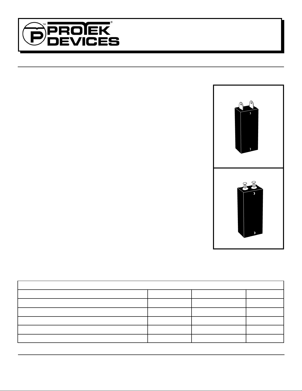
HIGH POWER AIRCRAFT/VEHICLE DC BUS VOLTAGE SUPPRESSOR
APPLICATIONS
15,000 WATTS
✔ DC P o wer Supply Protection
✔ MIL-STD-704 Po wer Bus Protection
IEC COMPATIBILITY (EN61000-4)
✔ 61000-4-5 (Surge): 95A, 8/20µs - Level 4(Line-Gnd) & 48A, Level 4(Line-Line)
FEATURES
✔
Meets the Following Military Specifications:
- MIL-STD-704 - MIL-PRF-19500
✔ 15 kilow atts P eak Pulse P ower per Line (tp=10/1000µs)
✔ Each De vice 100% Tested
✔ 28V P o wer Supply Protection
MECHANICAL CHARACTERISTICS
704-15K36
15,000 WATTS
✔ Molded Plastic Case
✔ Weight 38 grams: 704-15K36 (Appro x.) & 65 grams: 704-15K36T(Approx.)
✔ Flammability Rating UL 94V -0
✔ De vice Marking: Date Code, Logo & P art Number
✔ Screening for Military Requirements IA W MIL-PRF-19500 is Availab le
✔ Screening Upon Request - The 704 series can be screened upon request f or military
requirements in accordance with MIL-PRF-19500. Standard screening consists of 100%
JANTX equivalent level testing per MIL-PRF-19500.
For Ordering Options Use the Following Suffix:
H1 - Submodule Screening
H2 - Submodule & Module Screening
H3 - Submodule & Module Screening
Module Group B & C Lot Testing
MAXIMUM RATINGS @ 25°C Unless Otherwise Specified
PARAMETER
Peak Pulse P o wer (tp = 10/1000µs) - See Figure 1
Operating T emperature
Storage T emperature
Forward Surge Rating @ 25°C 1/120 seconds Amps300F
Steady State Po wer Dissipation @ 25°C
SYMBOL VALUE
P
PP
T
J
T
STG
I
T
A
-55°C to 150°C
-55°C to 150°C
704-15K36T
UNITS
1 5 kilowatts
°C
°C
10
Watts
1 www.protekdevices.com05021.R3 9/02
704-15K36
704-15K36T
DEVICE CHARACTERISTICS
ELECTRICAL CHARACTERISTICS PER LINE @ 25°C Unless Otherwise Specified
&
PART
NUMBER
704-15K36
704-15K36T
RATED
STAND-OFF
VOLTAGE
V
WM
VOLTS
31.5
31.5
- Peak Pulse Power - kilowatts
PP
P
MINIMUM
BREAKDOWN
VOLTAGE
@ 10mA
V
(BR)
VOLTS
36
36
MAXIMUM
CLAMPING
VOLTAGE
(See Fig. 2)
@ I
PPM
V
C
VOLTS
51
51
MAXIMUM
LEAKAGE
CURRENT
@V
WM
I
D
µA
100
500
MAXIMUM
PEAK PULSE
CURRENT
(See Fig. 2)
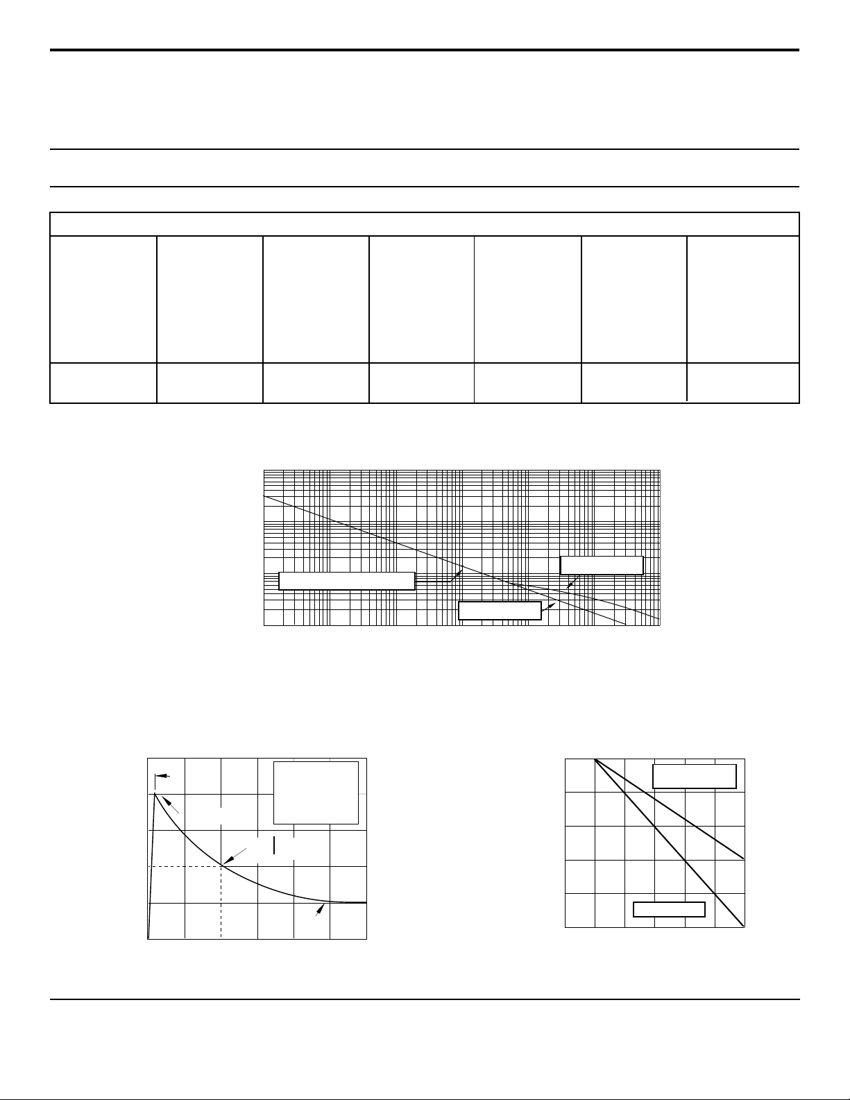
FIGURE 1
PEAK PULSE POWER VS PULSE TIME
1,000
100
10
15Kw 10/1000 µs Waveform
1
1 10 100 1,000 10,000 100,000 1,000,000
- Pulse Duration - µs
t
d
704-16K36
704-16K36T
I
PPM
AMPS
300
300
MAXIMUM
FORWARD
VOLTAGE
@100A, 8.3ms
I
F
VOLTS DC
3.0
15.0
100
PP
50
- Peak Pulse Current - % of I
PP
I
0
05021.R3 9/02
FIGURE 2
PULSE WAVE FORM
PP
td = t
TEST
WA VEFORM
P ARAMETERS
tf = 10µs
td = 1,000µs
IPP/2
-t
e
t
f
Peak V alue I
0 1 2 3
t - Time - ms
POWER DERATING CURVE
FIGURE 3
100
80
60
40
% Of Rated Power
20
0
0 25 50 75 100 125 150
2 www.protekdevices.com
- Lead Temperature - °C
T
L
Peak Pulse Power
10/1000µs
Average Power

PACKAGE OUTLINE & DIMENSIONS
704-15K36
&
704-15K36T
704-15K36 PACKAGE OUTLINE
A
BC
D
F
704-15K36
DIMENSIONS
H
E
I
L
J
K
704-15K36T PACKAGE OUTLINE
G
MILLIMETERS
DIM MIN MAX
E*
G
H*
A
B
C
D
F
I
J
K
L
49.28
43.92
2.79
18.29
3.18 DIA
8.76
13.51
0.69
11.94
2.41
7.70
9.40
51.56
44.96
3.56
19.81
3.18 DIA
10.29
15.04
0.69
13.46
2.92
8.20
10.92
INCHES
MIN MAX
1.97
1.73
0.110
0.72
0.125 DIA
0.345
0.532
0.027
0.47
0.095
0.303
0.37
2.03
1.77
0.140
0.78
0.125 DIA
0.405
0.592
0.027
0.53
0.115
0.323
0.43
704-15K36T
A
C
D
B
E
F
I
G
J
K
H
06035 Rev 0 - 4/02
COPYRIGHT © ProTek Devices 2001
SPECIFICA TIONS: ProT ek reserves the right to change the electrical and or mechanical characteristics described herein without
notice (except JEDEC).
DESIGN CHANGES: ProTek reserves the right to discontinue product lines without notice, and that the final judgement concerning
selection and specifications is the buyer’s and that in furnishing engineering and technical assistance, ProTek assumes no
3 www.protekdevices.com05021.R3 9/02
DIMENSIONS
MILLIMETERS
DIM MIN MAX
A
B
C
D
E*
F
G*
H
I*
J
K*
Note*: Dimensions are nominal
62.74
53.34
4.32
10.54
3.18 DIA
8.26
11.43
21.84
5.59
16.51
8.51
3.18 DIA
ProTek Devices
2929 South Fair Lane, Tempe, AZ 85282
T el: 602-431-8101 F ax: 602-431-2288
E-Mail: sales@protekdevices.com
Web Site: www.protekdevices.com
64.26
54.48
5.33
12.07
9.27
11.43
23.37
5.59
17.53
8.51
INCHES
MIN MAX
2.47
2.10
0.17
0.415
0.125 DIA
0.325
0.450
0.86
0.220
0.65
0.335
2.53
2.145
0.21
0.475
0.125 DIA
0.365
0.450
0.92
0.220
0.69
0.335
 Loading...